INSTALLATION INSTRUCTIONS - Split Air Conditioner ...€¦ · 4 2-2. Outdoor Unit AVOID: heat...
32
Contents Page IMPORTANT! Please Read Before Starting .................................. 1 1. GENERAL .......................................................... 2 1-1. Tools Required for Installation (not supplied) 1-2. Accessories Supplied with Indoor Unit 1-3. Optional Copper Tubing Kit 1-4. Type of Copper Tube and Insulation Material 1-5. Field Wiring 1-6. Additional Materials Required for Installation 1-7. Operating Range 2. INSTALLATION SITE SELECTION ................... 3 2-1. Indoor Unit 2-2. Outdoor Unit 2-3. Air Discharge Chamber for Top Discharge 2-4. Wind Shield for “CL” Model 3. HOW TO INSTALL THE INDOOR UNIT ........... 6 3-1. Remove the Rear Panel from the Unit 3-2. Make a Hole 3-3. Install the Rear Panel on the Wall 3-4. Remove the Grille to Install the Indoor Unit 3-5. Shape the Indoor Side Tubing 3-6. Wiring Instructions 3-7. Recommended Wire Length and Diameter 3-8. Wiring Instructions for Inter-unit Connections 3-9. Mounting 3-10. Drain Hose 4. REMOTE CONTROL UNIT INSTALLATION POSITION ........................................................ 14 4-1. Mounting on a Wall 5. ADDRESS SWITCHES ..................................... 15 6. HOW TO INSTALL THE OUTDOOR UNIT....... 16 6-1. Removing the Packaging Skid 6-2. Installing the Outdoor Unit 6-3. Tubing Direction Model Combinations Combine indoor and outdoor units only as listed below. Indoor Unit Outdoor Units KS2462R C2462R CL2462R Power supply: 60Hz, single-phase, 208/230V INSTALLATION INSTRUCTIONS – Split System Air Conditioner – COOL/DRY Model Units should be installed by a licensed contractor according to local code requirements. 7. ELECTRICAL WIRING ..................................... 17 7-1. General Precautions on Wiring 7-2. Recommended Wire Length and Wire Diameter for Power Supply System 7-3. Wiring System Diagram 7-4. Examples of Incorrect Wiring 8. HOW TO PROCESS TUBING .......................... 19 8-1. Use of the Flaring Method 8-2. Flaring Procedure with a Flare Tool 8-3. Caution before Connecting Tubes Tightly 8-4. Precautions During Brazing 8-5. Indoor Unit Tubing 8-6. Connecting Tubing between Indoor and Outdoor Units 8-7. Insulation of Refrigerant Tubing 8-8. Taping the Tubes 8-9. Finishing the Installation 9. AIR PURGING................................................... 22 10. TEST RUN......................................................... 25 10-1. Preparing for Test Run 10-2. Performing Test Run 11. REFRIGERANT R410A: SPECIAL PRECAUTIONS WHEN INSTALLING UNIT ................................ 28 11-1. Characteristics of New Refrigerant R410A 11-2. Checklist Before Installation 11-3. Tools Specifically for R410A 11-4. Charging Additional Refrigerant In Canada SANYO FISHER COMPANY SANYO Canada Inc. A DIVISION OF SANYO NORTH AMERICA CORPORATION 300 Applewood Crescent 21605 Plummer Street Concord, Ontario 85464359328000 © SANYO 2002 Chatsworth, CA 91311 U.S.A. L4K 5C7, Canada In order to protect the environment, this air conditioner uses the new refrigerant R410A.
Transcript of INSTALLATION INSTRUCTIONS - Split Air Conditioner ...€¦ · 4 2-2. Outdoor Unit AVOID: heat...

ContentsPage
IMPORTANT!Please Read Before Starting .................................. 1
1. GENERAL .......................................................... 21-1. Tools Required for Installation (not supplied)1-2. Accessories Supplied with Indoor Unit1-3. Optional Copper Tubing Kit1-4. Type of Copper Tube and Insulation Material1-5. Field Wiring1-6. Additional Materials Required for Installation1-7. Operating Range
2. INSTALLATION SITE SELECTION ................... 32-1. Indoor Unit2-2. Outdoor Unit2-3. Air Discharge Chamber for Top Discharge2-4. Wind Shield for “CL” Model
3. HOW TO INSTALL THE INDOOR UNIT ........... 63-1. Remove the Rear Panel from the Unit3-2. Make a Hole3-3. Install the Rear Panel on the Wall3-4. Remove the Grille to Install the Indoor Unit3-5. Shape the Indoor Side Tubing3-6. Wiring Instructions3-7. Recommended Wire Length and Diameter3-8. Wiring Instructions for Inter-unit Connections3-9. Mounting3-10. Drain Hose
4. REMOTE CONTROL UNIT INSTALLATIONPOSITION ........................................................ 144-1. Mounting on a Wall
5. ADDRESS SWITCHES..................................... 15
6. HOW TO INSTALL THE OUTDOOR UNIT....... 166-1. Removing the Packaging Skid6-2. Installing the Outdoor Unit6-3. Tubing Direction
Model Combinations
Combine indoor and outdoor units only as listedbelow.
Indoor Unit Outdoor Units
KS2462R C2462R
CL2462R
Power supply: 60Hz, single-phase, 208/230V
INSTALLATION INSTRUCTIONS
– Split System Air Conditioner – COOL/DRY Model
Units should be installed by a licensed contractoraccording to local code requirements.
7. ELECTRICAL WIRING ..................................... 177-1. General Precautions on Wiring7-2. Recommended Wire Length and Wire
Diameter for Power Supply System7-3. Wiring System Diagram7-4. Examples of Incorrect Wiring
8. HOW TO PROCESS TUBING .......................... 198-1. Use of the Flaring Method8-2. Flaring Procedure with a Flare Tool8-3. Caution before Connecting Tubes Tightly8-4. Precautions During Brazing8-5. Indoor Unit Tubing8-6. Connecting Tubing between Indoor and
Outdoor Units8-7. Insulation of Refrigerant Tubing8-8. Taping the Tubes8-9. Finishing the Installation
9. AIR PURGING................................................... 22
10. TEST RUN......................................................... 2510-1. Preparing for Test Run10-2. Performing Test Run
11. REFRIGERANT R410A: SPECIAL PRECAUTIONS WHEN INSTALLING UNIT................................ 2811-1. Characteristics of New Refrigerant R410A11-2. Checklist Before Installation11-3. Tools Specifically for R410A11-4. Charging Additional Refrigerant
In CanadaSANYO FISHER COMPANY SANYO Canada Inc.A DIVISION OF SANYO NORTH AMERICA CORPORATION 300 Applewood Crescent21605 Plummer Street Concord, Ontario
85464359328000 © SANYO 2002 Chatsworth, CA 91311 U.S.A. L4K 5C7, Canada
In order to protect the environment, this air conditioner uses the new refrigerant R410A.
02-291AirCon Final 12/11/02 2:45 PM Page a

1
IMPORTANT! Please Read Before StartingThis air conditioning system meets strict safety and operat-ing standards. As the installer or service person, it is animportant part of your job to install or service the system soit operates safely and efficiently.
For safe installation and trouble-free operation, you must:● Carefully read this instruction booklet before beginning.● Follow each installation or repair step exactly as
shown.● Observe all local, state, and national electrical codes.● Pay close attention to all warning and caution notices
given in this manual.This symbol refers to a hazard orunsafe practice which can resultin severe personal injury ordeath.
This symbol refers to a hazardor unsafe practice which canresult in personal injury or prod-uct or property damage.
If Necessary, Get Help
These instructions are all you need for most installationsites and maintenance conditions. If you require help for aspecial problem, contact our sales/service outlet or yourcertified dealer for additional instructions.
In Case of Improper Installation
The manufacturer shall in no way be responsible forimproper installation or maintenance service, includingfailure to follow the instructions in this document.
SPECIAL PRECAUTIONSWhen Wiring
ELECTRICAL SHOCK CAN CAUSE SEVERE PER-SONAL INJURY OR DEATH. ONLY A QUALIFIED,EXPERIENCED ELECTRICIAN SHOULD ATTEMPTTO WIRE THIS SYSTEM.
• Do not supply power to the unit until all wiring and tub-ing are completed or reconnected and checked.
• Highly dangerous electrical voltages are used in thissystem. Carefully refer to the wiring diagram and theseinstructions when wiring. Improper connections andinadequate grounding can cause accidental injury ordeath.
• Ground the unit following local electrical codes.• Connect all wiring tightly. Loose wiring may cause over-
heating at connection points and a possible fire hazard.
When Transporting
Be careful when picking up and moving the indoor and out-door units. Get a partner to help, and bend your knees whenlifting to reduce strain on your back. Sharp edges or thin alu-minum fins on the air conditioner can cut your fingers.
When Installing…
…In a Ceiling, Wall or Floor
Make sure the ceiling/wall/floor is strong enough to holdthe unit’s weight. It may be necessary to construct astrong wood or metal frame to provide added support.
…In a Room
Properly insulate any tubing run inside a room to prevent“sweating” that can cause dripping and water damage towalls and floors.
…In Moist or Uneven Locations
Use a raised concrete pad or concrete blocks to provide asolid, level foundation for the outdoor unit. This preventswater damage and abnormal vibration.
…In an Area with High Winds
Securely anchor the outdoor unit down with bolts and ametal frame. Provide a suitable air baffle.
…In a Snowy Area (for Heat Pump-type Systems)
Install the outdoor unit on a raised platform that is higherthan drifting snow. Provide snow vents.
When Connecting Refrigerant Tubing
• Use the flare method for connecting tubing.
• Apply refrigerant lubricant to the matching surfaces ofthe flare and union tubes before connecting them, thentighten the nut with a torque wrench for a leak-free con-nection.
• Check carefully for leaks before starting the test run.
When Servicing
• Turn the power OFF at the main power box (mains)before opening the unit to check or repair electricalparts and wiring.
• Keep your fingers and clothing away from any movingparts.
• Clean up the site after you finish, remembering to checkthat no metal scraps or bits of wiring have been leftinside the unit being serviced.
Others
• Ventilate any enclosed areas when installing or testingthe refrigeration system. Escaped refrigerant gas, oncontact with fire or heat, can produce dangerously toxicgas.
• Confirm upon completing installation that no refrigerantgas is leaking. If escaped gas comes in contact with astove, gas water heater, electric room heater or otherheat source, it can produce dangerously toxic gas.
WARNING
WARNING
CAUTION
CAUTION
02-291AirCon Final 12/11/02 2:45 PM Page 1
2
1. General
This booklet briefly outlines where and how to install theair conditioning system. Please read over the entire setof instructions for the indoor and outdoor units and makesure all accessory parts listed are with the system beforebeginning.
1-1. Tools Required for Installation (not supplied)1. Standard screwdriver2. Phillips head screwdriver3. Knife or wire stripper4. Tape measure5. Carpenter’s level
6. Sabre saw or key hole saw7. Hacksaw8. Core bits9. Hammer
10. Drill11. Tube cutter12. Tube flaring tool13. Torque wrench14. Adjustable wrench15. Reamer (for deburring)16. Pipe bending tool (spring bender)
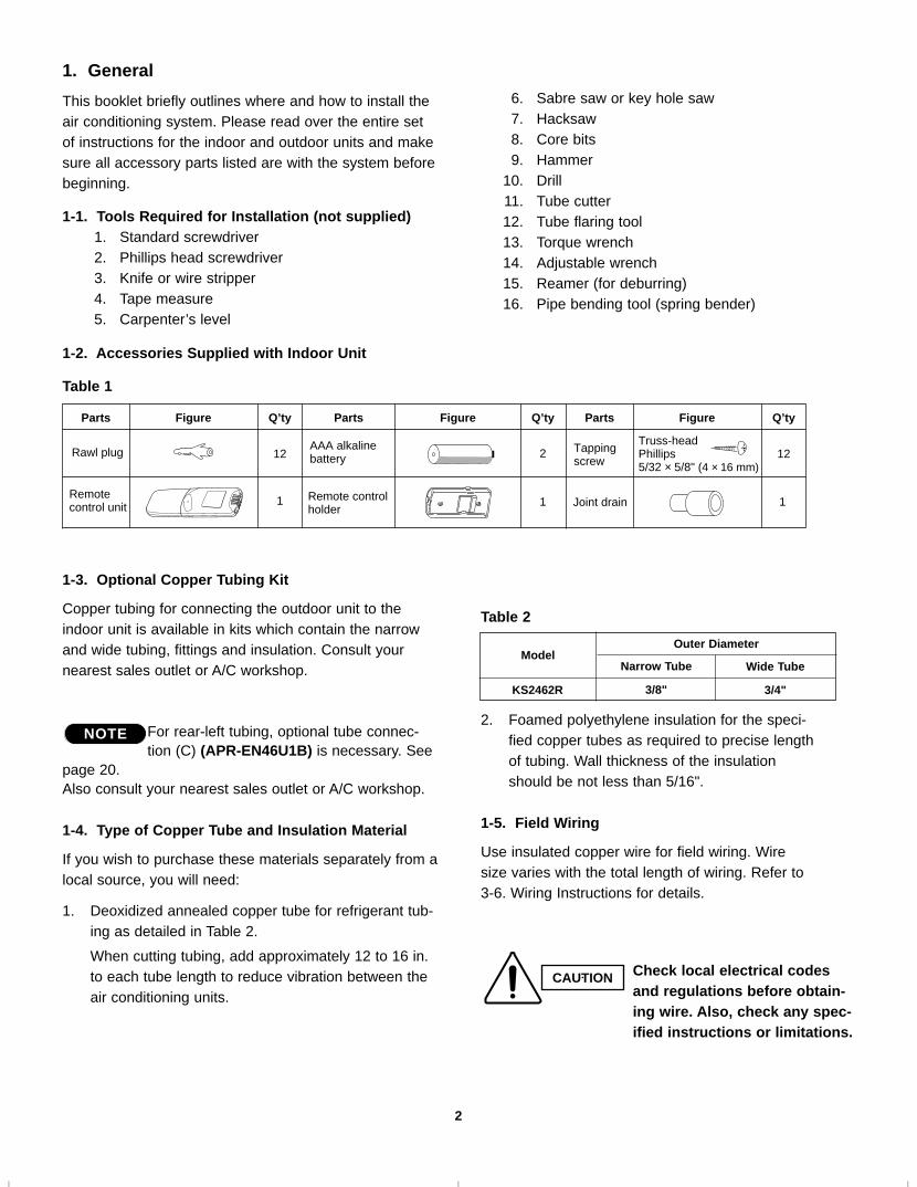
1-2. Accessories Supplied with Indoor Unit
Table 1
1-3. Optional Copper Tubing Kit
Copper tubing for connecting the outdoor unit to theindoor unit is available in kits which contain the narrowand wide tubing, fittings and insulation. Consult yournearest sales outlet or A/C workshop.
For rear-left tubing, optional tube connec-tion (C) (APR-EN46U1B) is necessary. See
page 20.Also consult your nearest sales outlet or A/C workshop.
1-4. Type of Copper Tube and Insulation Material
If you wish to purchase these materials separately from alocal source, you will need:
1. Deoxidized annealed copper tube for refrigerant tub-ing as detailed in Table 2.
When cutting tubing, add approximately 12 to 16 in.to each tube length to reduce vibration between theair conditioning units.
Parts Figure Q’ty Parts Figure Q’ty
12
1 1Remotecontrol unit
Parts Figure Q’ty
12Tappingscrew
Truss-headPhillips5/32 × 5/8" (4 × 16 mm)
2
1
AAA alkalinebattery
Joint drain
Rawl plug
Remote controlholder
NOTE
Table 2
2. Foamed polyethylene insulation for the speci-fied copper tubes as required to precise lengthof tubing. Wall thickness of the insulationshould be not less than 5/16".
1-5. Field Wiring
Use insulated copper wire for field wiring. Wiresize varies with the total length of wiring. Refer to3-6. Wiring Instructions for details.
Outer DiameterModel
KS2462R
Narrow Tube
3/8"
Wide Tube
3/4"
CAUTION Check local electrical codesand regulations before obtain-ing wire. Also, check any spec-ified instructions or limitations.
02-291AirCon Final 12/11/02 2:45 PM Page 2

3
1-6. Additional Materials Required for Installation
1. Refrigeration (armored) tape2. Insulated staples or clamps for connecting wire
(See local codes)3. Putty4. Refrigeration lubricant5. Clamps or saddles to secure refrigerant tubing
1-7. Operating Range
*CL Models
2. Installation Site Selection
2-1. Indoor Unit
AVOID:
● direct sunlight.● nearby heat sources that may affect performance of the
unit.● areas where leakage of flammable gas may be expected.● places where large amounts of oil mist exist.
DO:
● select an appropriate position from which every corner ofthe room can be uniformly cooled. (High on a wall is best.)
● select a location that will hold the weight of the unit.● select a location where tubing and drain hose have the
shortest run to the outside. (Fig. 1)● allow room for operation and maintenance as well as
unrestricted air flow around the unit. (Fig. 2)● install the unit within the maximum elevation difference
(H) above or below the outdoor unit and within a totaltubing length (L) from the outdoor unit as detailed inTable 3 and Fig. 3a.
Table 3
6 in.min.
6 in.min.
6 in. min.
Front View
Fig. 2
INDOORUNIT
Tubing length (L)
OUTDOORUNIT
Elevationdifference (H)
Fig. 3a
Max. Allowable Tubing Limit of Tubing Limit of Elevation Required Amount of
Model Length at Shipment Length (L) Difference (H) Additional Refrigerant(ft.) (ft.) (ft.) (oz./ft.)*
C2462R, CL2462R 23 132 50 0.43
* If total tubing length becomes 23 to 132 ft. (max.), additional refrigerant (R410A) charge of 0.43 oz./ft. is required.No additional charge of compressor oil is necessary.
Indoor unit
Floor level
Wall
Minimum height from floor level
5 ft.
Fig. 3b
For stable operation ofthe air conditioner, donot install wall-mountedtype indoor units lessthan 5 ft. from floorlevel.
CAUTION
Drain hose
Indoor unit
Outside drainage
Fig. 1Temperature Indoor Air Intake Outdoor Air Intake
Cooling Maximum 95°F DB, 71°F WB 115°F DBMinimum 67°F DB, 57°F WB 67°F DB, (0°F DB)*
WARNINGTo prevent abnormal heat genera-tion and the possibility of fire, donot place obstacles, enclosures andgrilles in front of or surrounding theair conditioner in a way that mayblock air flow.
02-291AirCon Final 12/11/02 2:46 PM Page 3

4
2-2. Outdoor Unit
AVOID:
● heat sources, exhaust fans, etc. (Fig. 4a)
● damp, humid or uneven locations.
DO:● choose a place as cool as possible.
● choose a place that is well ventilated.
● allow enough room around the unit for air intake/
exhaust and possible maintenance. (Fig. 4b)● provide a solid base a minimum of 6 inches above
ground level to reduce humidity and protect the unitagainst possible water damage and decreased servicelife. (Fig. 4c)
● use lug bolts or equal to bolt down unit, to reduce
vibration and noise.
2-3. Air Discharge Chamber for Top Discharge
Install the air-discharge chamber in the field when:● it is difficult to keep a space of minimum 2 ft. between
the air-discharge outlet and an obstacle.● the air-discharge outlet faces a sidewalk and dis-
charged hot air may disturb people passing by.Refer to Fig. 5a.
Outdoor unit
Hot airHeat source
Exhaust fan
Fig. 4a
Min.1 in. Min.
1 in.
Min. 2 ft.
Min. 4 inchesMin.7 ft.
Obstacle above
Ground
Airdis-charge
Fig. 4b
Air inAir in
Airdischarge
Concrete block4 in. × 1 ft. 4 in.beams or equal
Anchor bolts(4 pieces)
Min. 6 in.
Fig. 4c
Fig. 5a
Air discharge
02-291AirCon Final 12/11/02 2:46 PM Page 4

5
2-4. Wind Shield for “CL” Model
It is recommended to use wind shields for “CL” model(Fig. 5b). “CL” model is designed to use in low outdoortemperature conditions.
GeneralWhen the outdoor unit is installed in a position exposedto strong wind (like seasonal winds with low air tempera-ture in winter), a suitable wind shield must be installedon the outdoor unit.
This unit is designed so that the fan of the outdoor unitruns at low speed when the air conditioner is operated atlow outdoor air temperatures. When the outdoor unit isexposed to strong wind, the system pressure dropsbecause of the freeze protector.
For outer dimensions of the wind shield, see Fig. 5c.
IMPORTANT
Wind shield(air discharge side)
Front
3 - φ1-9/16" h
ole
6 - φ15/64" h
ole
9-27
/32"
21-5
/8"
15/1
6"
5-3/
16"
22-7
/16"
1/2"
23-1
5/32
"
21-13/16"
5-5/32"9-27/32"9-27/32"1-1/16"
21-13/16"
Fig. 5b
Fig. 5c
CL2462R
Recommended outer dimensions of wind shield (field supply)
02-291AirCon Final 12/11/02 2:46 PM Page 5

6
Indoorside
Outdoorside
Set screws for transportation only
Right-reartubing(recommended)
Right tubing
Left-rear tubling
Fig. 6
Fig. 7a
Center ofleft-reartubing hole
Center ofright-reartubing hole
Fig. 7b
NOTE
Hole should be made at a slight downward slant to theoutdoor side.
In case of left-rear or right-rear tubing
Fig. 8
3. How to Install the Indoor Unit
3-1. Remove the Rear Panel from the Unit
Remove and discard the set screws and take off the rearpanel. (Fig. 6)
Tubing can be extended in 3 directions as shown in Fig. 7a. Select the direction you need providing theshortest run to the outside unit.
3-2. Make a Hole
(1) Remove the rear panel from the indoor unit andplace it on the wall at the location selected. Makesure the unit is horizontal, using a carpenter’s levelor tape measure to measure down from the ceiling.
(2) Determine which side of the unit you should makethe hole. (Fig. 7b)
(3) Before making a hole, check carefully that no studsor pipes are directly run behind the spot to be cut.
The above precautions are also applicable if tubinggoes through the wall in any other location.
(4) Using a sabre saw, key hole saw or hole-cutting drillattachment, cut a hole in the wall. See Table 4 andFig. 8.
Table 4
(5) Measure the thickness of the wall from the insideedge to the outside edge and cut PVC pipe at aslight angle 1/4" shorter than the thickness of thewall. (Fig. 9)
(6) Place the plastic cover over the end of the pipe (forindoor side only) and insert in the wall. (Fig. 10)
NOTE
CAUTION Also avoid areas where electri-cal wiring or conduits arelocated.
Hole Dia. (inch)
3-3/16"
Plastic cover(Field supply)
OUTSIDEINSIDEWall
Slightangle
PVC pipe
Fig. 10
PVC pipe (locally purchased)
Cut at slight angle
Fig. 9
02-291AirCon Final 12/11/02 2:46 PM Page 6
7
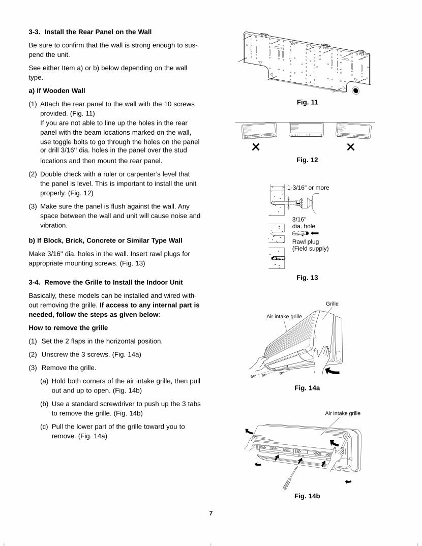
3-3. Install the Rear Panel on the Wall
Be sure to confirm that the wall is strong enough to sus-pend the unit.
See either Item a) or b) below depending on the walltype.
a) If Wooden Wall
(1) Attach the rear panel to the wall with the 10 screwsprovided. (Fig. 11)If you are not able to line up the holes in the rearpanel with the beam locations marked on the wall,use toggle bolts to go through the holes on the panelor drill 3/16" dia. holes in the panel over the stud
locations and then mount the rear panel.
(2) Double check with a ruler or carpenter’s level thatthe panel is level. This is important to install the unitproperly. (Fig. 12)
(3) Make sure the panel is flush against the wall. Anyspace between the wall and unit will cause noise andvibration.
b) If Block, Brick, Concrete or Similar Type Wall
Make 3/16" dia. holes in the wall. Insert rawl plugs forappropriate mounting screws. (Fig. 13)
3-4. Remove the Grille to Install the Indoor Unit
Basically, these models can be installed and wired with-out removing the grille. If access to any internal part isneeded, follow the steps as given below:
How to remove the grille
(1) Set the 2 flaps in the horizontal position.
(2) Unscrew the 3 screws. (Fig. 14a)
(3) Remove the grille.
(a) Hold both corners of the air intake grille, then pullout and up to open. (Fig. 14b)
(b) Use a standard screwdriver to push up the 3 tabsto remove the grille. (Fig. 14b)
(c) Pull the lower part of the grille toward you toremove. (Fig. 14a)
Fig. 11
Fig. 12
3/16"dia. hole
1-3/16" or more
Rawl plug(Field supply)
Fig. 13
Air intake grille
Grille
Fig. 14a
Air intake grille
Fig. 14b
02-291AirCon Final 12/11/02 2:46 PM Page 7

8
How to replace the grille
(1) Close the flaps.
(2) Reinstall the grille into the lower part while aligningits tabs on the upper part. (Fig. 15a) Insert the tabsin the slots and push the lower part of the grille backinto position.
(3) Press at each of the 5 tabs to completely close thegrille. Make sure that the grille and frame are firmlyfitted together. (Fig. 15b)
3-5. Shape the Indoor Side Tubing
1) Arrangement of tubing by directions
a) Right tubing
The corner of the right frame needs to be cut by ahacksaw or the like. (Fig. 16)
b) Right-rear or left-rear tubing
In this case, the corner of the frame need not becut.
2) To mount the indoor unit on the rear panel:
Hang the 3 mounting slots of the unit on theupper tabs of the rear panel. (Fig. 17)
3-6. Wiring Instructions
General precautions on wiring
1) Before wiring, confirm the rated voltage of the unit asshown on its nameplate, then carry out the wiringclosely following the wiring diagram.
2) Provide a power outlet to be used exclusively foreach unit, with a power supply disconnect and circuitbreaker for overcurrent protection provided in theexclusive line.
3) To prevent possible hazard due to insulation failure,the unit must be grounded.
4) Each wiring connection must be done tightly and inaccordance with the wiring system diagram. Wrongwiring may cause the unit to misoperate or becomedamaged.
5) Do not allow wiring to touch the refrigerant tubing,compressor, or any moving parts of the fan.
6) Unauthorized changes in the internal wiring can bevery dangerous. The manufacturer will accept noresponsibility for any damage or misoperation thatoccurs as a result of such unauthorized changes.
Frame
Right tubingoutlet
Fig. 16
TabMounting slot
Fig. 17
Fig. 15a
Fig. 15b
02-291AirCon Final 12/11/02 2:46 PM Page 8

9
3-7. Recommended Wire Length and Diameter
Regulations on wiring diameter differ from locality tolocality. For field wiring requirements, please refer toyour local electrical codes. Carefully observe these regu-lations when carrying out the installation.Table 5 lists recommended wire lengths and diametersfor power supply systems.Refer to the wiring system diagram (Fig. 18) for themeaning of “A” and “B” in Table 5.
Table 5
2
4
2
4
1 1
INDOORUNIT
Terminal
OUTDOOR UNIT
(B)
Terminal
(A)
L2
L1
G G
G
230V/208V
230V/208V
230V/208V
(Inter-unit)power line
Grounding line
Grounding line
Pow
er s
uppl
yS
ingl
e-ph
ase
230V
/208
V 6
0HZ
Disconnect switchField supply
Fig. 18
WARNING ● Be sure to comply with localcodes on running the wirefrom the indoor unit to theoutdoor unit (size of wire andwiring method, etc.).
● Each wire must be firmlyconnected.
● No wire should be allowed totouch refrigerant tubing, thecompressor, or any movingpart.
CAUTION Be sure to connect the powersupply line to the outdoor unitas shown in the wiring dia-gram. The indoor unit draws itspower from the outdoor unit.
To avoid the risk of electricshock, each air conditioner unit must be grounded.
WARNING
# … AWG (American Wire Gauge)
WIRING SYSTEM DIAGRAM
AWG
Model
C2462R, CL2462R 64 (Max.) 132 (Max.) 35A
(A) Power Supply Wiring Length (ft.)
(B) Inter-UnitPower Line
Fuse or CircuitCapacity
(#12) (#14)
02-291AirCon Final 12/11/02 2:46 PM Page 9

10
3-8. Wiring Instructions for Inter-unit Connections
(1) Insert the inter-unit wiring (according to local codes)into the through-the-wall PVC pipe. Run the wiringtoward the indoor side allowing approx. 10 inches toextend from the wall face. (Fig. 19)
(2) Route the inter-unit wiring from the back of theindoor unit and pull it toward the front for connection.(Figs. 20a and 20b)
(3) Connect the inter-unit wiring to the correspondingterminals on the terminal plate (Figs. 20a and 20b)while referring to the wiring diagram.
(4) Be sure to secure the wiring with the providedclamp.
How to remove the cover plate
To access the terminal plate inside the indoor unit, followthese steps.
(1) Using a Phillips screwdriver, remove the screw onthe cover plate. (Figs. 20a and 20b)
(2) Remove the cover plate.
Rearpanel
Wiring
Wall
10 in.
Plasticcover
Fig. 19
Terminalplate
Cover plate
Fig. 20a
Fig. 20b
Lock nut
Top of conduitconnector
Inter-unitcontrol linewiring
Earthplate
02-291AirCon Final 12/11/02 2:46 PM Page 10
11
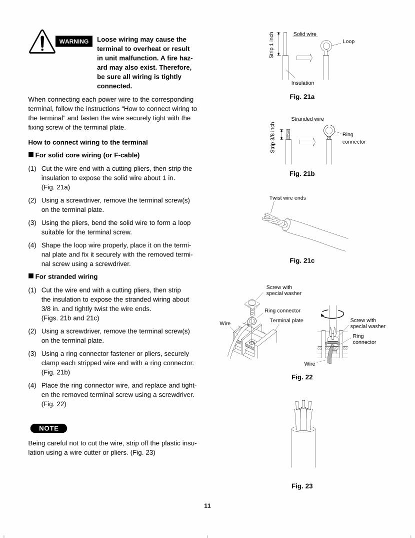
When connecting each power wire to the correspondingterminal, follow the instructions “How to connect wiring tothe terminal” and fasten the wire securely tight with thefixing screw of the terminal plate.
How to connect wiring to the terminal
■ For solid core wiring (or F-cable)
(1) Cut the wire end with a cutting pliers, then strip theinsulation to expose the solid wire about 1 in. (Fig. 21a)
(2) Using a screwdriver, remove the terminal screw(s)on the terminal plate.
(3) Using the pliers, bend the solid wire to form a loopsuitable for the terminal screw.
(4) Shape the loop wire properly, place it on the termi-nal plate and fix it securely with the removed termi-nal screw using a screwdriver.
■ For stranded wiring
(1) Cut the wire end with a cutting pliers, then strip the insulation to expose the stranded wiring about3/8 in. and tightly twist the wire ends. (Figs. 21b and 21c)
(2) Using a screwdriver, remove the terminal screw(s)on the terminal plate.
(3) Using a ring connector fastener or pliers, securelyclamp each stripped wire end with a ring connector.(Fig. 21b)
(4) Place the ring connector wire, and replace and tight-en the removed terminal screw using a screwdriver.(Fig. 22)
Being careful not to cut the wire, strip off the plastic insu-lation using a wire cutter or pliers. (Fig. 23)
NOTE
Solid wireLoop
Insulation
Str
ip 1
inch
Fig. 21a
Stranded wire
Ringconnector
Str
ip 3
/8 in
ch
Fig. 21b
Screw withspecial washer
Ring connector
Terminal plateWire
Fig. 22
Screw with special washer
Ringconnector
Wire
WARNING Loose wiring may cause theterminal to overheat or resultin unit malfunction. A fire haz-ard may also exist. Therefore,be sure all wiring is tightlyconnected.
Twist wire ends
Fig. 21c
Fig. 23
02-291AirCon Final 12/11/02 2:46 PM Page 11
12
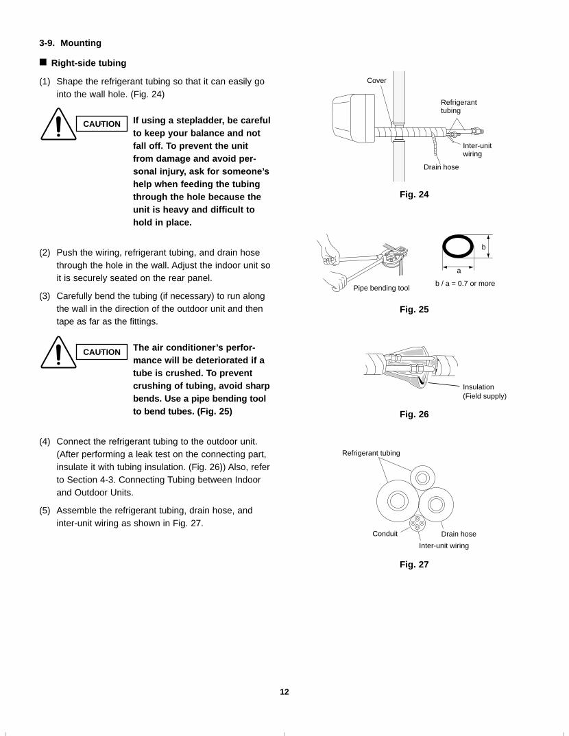
3-9. Mounting
■ Right-side tubing
(1) Shape the refrigerant tubing so that it can easily gointo the wall hole. (Fig. 24)
(2) Push the wiring, refrigerant tubing, and drain hosethrough the hole in the wall. Adjust the indoor unit soit is securely seated on the rear panel.
(3) Carefully bend the tubing (if necessary) to run alongthe wall in the direction of the outdoor unit and thentape as far as the fittings.
(4) Connect the refrigerant tubing to the outdoor unit.(After performing a leak test on the connecting part,insulate it with tubing insulation. (Fig. 26)) Also, referto Section 4-3. Connecting Tubing between Indoorand Outdoor Units.
(5) Assemble the refrigerant tubing, drain hose, andinter-unit wiring as shown in Fig. 27.
Cover
Refrigeranttubing
Drain hose
Inter-unitwiring
Fig. 24
Pipe bending tool
a
b
b / a = 0.7 or more
Fig. 25
Insulation(Field supply)
Fig. 26
Refrigerant tubing
Drain hose Conduit
Inter-unit wiring
Fig. 27
CAUTION If using a stepladder, be carefulto keep your balance and notfall off. To prevent the unitfrom damage and avoid per-sonal injury, ask for someone’shelp when feeding the tubingthrough the hole because theunit is heavy and difficult tohold in place.
CAUTION The air conditioner’s perfor-mance will be deteriorated if atube is crushed. To preventcrushing of tubing, avoid sharpbends. Use a pipe bending toolto bend tubes. (Fig. 25)
02-291AirCon Final 12/11/02 2:46 PM Page 12

13
3-10. Drain Hose
a) The drain hose should be slanted downward to theoutdoors. (Fig. 28)
b) Never form a trap in the course of the hose.
c) If the drain hose will run in the room, insulate thehose with insulation* so that chilled condensationwill not damage furniture or floors. (Fig. 29)
* Foamed polyethylene or its equivalent is recom-mended.
������
�������
����
�Slant
Drainhose
Indoorunit
Fig. 28
WARNING
Risk of Electric Shock
Do not supply power to theunit or operate it until all tub-ing and wiring to the outsideunit are completed.
������ ����
����
������
����
Condensation
Insulation material(locally purchased)must be used.
Fig. 29
02-291AirCon Final 12/11/02 2:46 PM Page 13

14
4. Remote Control Unit Installation Position
The remote control unit can be operated from either anon-fixed position or a wall-mounted position.
To ensure that the air conditioner operates correctly, donot install the remote control unit in the following places:
● In direct sunlight
● Behind a curtain or other place where it is covered
● More than 26 ft. (8 m) away from the air conditioner
● In the path of the air conditioner’s airstream
● Where it may become extremely hot or cold
● Where it may be subject to electrical or magneticinterference
4-1. Mounting on a Wall
1) Confirm the indoor unit beeps when the ON/OFFbutton is pressed at the wall location where theremote control unit is to be attached, then attachthe holder to the wall. (Fig. 30)
2) When taking out the remote control unit, graspand pull it from the holder.
When using the remote control unit
• Point the transmission portion of the remote con-trol unit at the receiver area of the indoor unit tocontrol the air conditioner.
• Do not place objects that may block the transmit-ted signals between the receiver and the remotecontrol unit.
When mounting the remote control unit to prevent theft or loss
1) Mount the holder to the wall with one of thescrews (using only the hole in the top of theholder) (Fig. 31).
2) Remove the cover of the remote control unit andtake out the batteries. Next, place the remotecontrol unit in the holder.
3) Fasten both the remote control unit and holder tothe wall with the remaining screw (using the holein the bottom of the holder).
4) Install the batteries in the remote control unit andclose the cover.
Truss-headtapping screw5/32 × 5/8" (4 × 16 mm supplied)
Remotecontrolunit holder
Holder
Holder
Truss-headtapping screw5/32 × 5/8" (4 × 16 mm supplied)
Fig. 31
Fig. 30
02-291AirCon Final 12/11/02 2:46 PM Page 14

15
5. Address Switches
● Change the address switch to prevent mixing of sig-nals from remote control units when 2 Sanyo air con-ditioners are installed next to each other. Normally,the address switch is set to A. To change the addressto B, break tab A of the remote control address switchand cut the jumper cable (JP11) on the indoor unitboard. (Figs. 32 and 33) If you need more information, contact your air condi-tioning system dealer.
● Normally, the tabs on the remote control unit shouldnot be broken. Address switch
(tab A)
Fig. 32
Fig. 33JP11
The illustration above pictures the remote controlunit after the cover has been lowered and removed.
NOTE
02-291AirCon Final 12/11/02 2:46 PM Page 15

16
6. How to Install the Outdoor Unit
6-1. Removing the Packing Skid
Remove the packing skid from the bottom. (Fig. 34)
Place the unit on a level concrete pad, block or equaland anchor.
Refer to Section 2. “Installation Site Selection.”
6-2. Installing the Outdoor Unit
(1) Install blocks or a solid platform under the outdoorunit which provides a minimum height of 6 in. fromground level. (Fig. 35)
(2) The outdoor unit must be bolted down tightly to theblocks or platform with 4 anchor bolts.
6-3. Tubing Direction
● Tubing can be extended in 4 different directions asshown in Fig. 36.
● Service valves are housed inside the unit. To accessthem, remove the access panel by removing the 3attaching screws, then slide the panel downward andpull it toward you. If either rear, right or front tubing is needed, punchout the knockout holes with a hammer and punch orsimilar tool.
● After punching out the knockout holes, mount plasticprotectors on the tubing outlets. There accessoriesare packed inside the unit and can be accessedthrough the access panel.
● Use tube benders to extend refrigerant tubing to theoutside.
Compressor
Packingskid
Fig. 34
Fig. 35
Fig. 36
6-11/16 26 4-21/64
Anchorbolts(not supplied)
Height :Min: 6 in.
1-3/
161-
3/16
15-3
/4
14-3
1/32
13-3
/8Unit: inch
Access panel
FrontTubingoutlets
Down
Right
RearInter-unitwiring outlets
Powersupply wiringoutlets
Powersupply line
Inter-unitpower line
Power supply line Inter unit power line1/2" 1/2"
02-291AirCon Final 12/11/02 2:46 PM Page 16

17
7. Electrical Wiring
7-1. General Precautions on Wiring
(1) Before wiring, confirm the rated voltage of the unitas shown on its nameplate, then carry out the wiringclosely following the wiring diagram.
(2) Provide a power outlet to be used exclusively foreach unit, and a power supply disconnect and circuitbreaker for overcurrent protection should be provid-ed in the exclusive line.
(3) To prevent possible hazards from insulation failure,the unit must be grounded.
(4) Each wiring connection must be done in accordancewith the wiring system diagram. Wrong wiring maycause the unit to misoperate or become damaged.
(5) Do not allow wiring to touch the refrigerant tubing,compressor, or any moving parts of the fan.
(6) Unauthorized changes in the internal wiring can bevery dangerous. The manufacturer will accept noresponsibility for any damage or misoperation thatoccurs as a result of such unauthorized changes.
(7) Regulations on wire diameters differ from locality tolocality. For field wiring rules, please refer to yourLOCAL ELECTRICAL CODES before beginning.You must ensure that installation complies with allrelevant rules and regulations.
(8) To prevent malfunction of the air conditioner causedby electrical noise, care must be taken when wiringas follows:
● The inter-unit control wiring and the remote con-trol wiring (option) should be wired apart from theinter-unit power wiring.
● It is recommended that shielded wires or twisted-pair wires be used for the remote control and theinter-unit control wiring if the air conditioner isinstalled where it is exposed to the influence ofelectrical and/or electro-magnetic noise.
7-2. Recommended Wire Length and Wire Diameter for Power Supply System
Models
Time DelayFuse orCircuitCapacity
(B)*1 Inter-unitWiring
(A)*1 Power Supply
AGW #14
C2462R, CL2462R 64 ft. (AWG #12) 35 A132 ft.
*1 Refer to the Wiring System Diagrams (See below diagram) for the meaning of “A” and “B.”AWG = American Wire Gauge
1
2
G
4
1
2
4
G
L1
L2
G
Indoor Unit Outdoor Unit
Ground
(B)
(A)
Ground
Disconnect SW(Field supply)
To access the electrical component box, open the airintake grille and remove the electrical component boxcover.
7-3. Wiring System Diagram
Outdoor Unit: “C”, “CL” modelsSingle-phase60 Hz, 208/230 V
NOTE
02-291AirCon Final 12/11/02 2:46 PM Page 17

18
CAUTION
7-4. Examples of Incorrect Wiring
The following are examples of improper wiring that resultin system misoperation. You should confirm that youhave wired the units correctly before beginning the TestRun described on page 25.
Problem 1
● Short circuit will occur after approx. 3 minutes.
Problem 2
● Air conditioner will not operate.
Problem 3
● Compressor will not start; only indoor unit willoperate.
1
4
2
G G
Indoor unit Outdoor unit
1
4
2
G G
1
4
2
Indoor unit Outdoor unit
1
4
2
G G
1
4
2
Indoor unit Outdoor unit
1
2
4
G G
1
4
2
Indoor unit Outdoor unit
1
2
4
G G
1
4
2
Indoor unit Outdoor unit
1
2
4
02-291AirCon Final 12/11/02 2:46 PM Page 18

19
Deburring
Before After
Fig. 37
Reamer
Coppertubing
Fig. 38a
Flare tool
Flare nut
Copper tubing
Fig. 38b
Apply refrigerant lubricant here and here
Fig. 39a
8. How to Process Tubing
The narrow tubing side is connected by a flare nut, andthe wide tubing side is connected by brazing.
8-1. Use of the Flaring Method
Many of conventional split system air conditioners employ theflaring method to connect refrigerant tubes which runbetween indoor and outdoor units. In this method, the coppertubes are flared at each end and connected with flare nuts.
8-2. Flaring Procedure with a Flare Tool
(1) Cut the copper tube to the required length with a tubecutter. It is recommended to cut approx. 12 to 16 in.longer than the tubing length you estimate.
(2) Remove burrs at the end of the copper tube with a tubereamer or file. This process is important and should bedone carefully to make a good flare. (Fig. 37)
When reaming, hold the tube end downward and be surethat no copper scraps fall into the tube. (Fig. 38a)
(3) Remove the flare nut from the unit and be sure tomount it on the copper tube.
(4) Make a flare at the end of copper tube with a flaretool.* (Fig. 38b)
(*Use “RIGID®” or equivalent.)
(5) Use the special flare tool for R410A for making a flare.If the conventional flare tool (for R22) is used, theflared portion of the tubing should protrude 1.0 to 1.5 mm. (Fig. 38c)
A good flare should have the following characteristics:● inside surface is glossy and smooth.
● edge is smooth.
● tapered sides are of uniform length.
8-3. Caution before Connecting Tubes Tightly
(1) Apply a sealing cap or water-proof tape to prevent dustor water from entering the tubes before they are used.
(2) Apply refrigerant lubricant to the matching surfacesof the flare and union before connecting themtogether. This helps to reduce gas leaks. (Fig. 39a)
NOTE
NOTE
0 to 0.5 mm
Fig. 38c
When R410Aflare tool is used
1.0 1.5 mm
When conventional flare tool isused (clutching method)
Flare the tubing by 1.0 to 1.5 mm.
(See 11. REFRIGERANT R410A: SPECIAL PRECAUTIONS)
02-291AirCon Final 12/11/02 2:46 PM Page 19

20
(3) For proper connection, align the union tube and flare tubewith each other, then screw in the flare nut lightly at first toobtain a smooth match. (Fig. 39b)
● Adjust the shape of the narrow and wide tubes using a tube
bender at the installation site and connect them to the eachtubing side valve using a flare nut.
8-4. Precautions During Brazing
● Replace air inside the tube with nitrogen gas to prevent cop-per oxide film from forming during the brazing process.
● Do not allow the tubing to get too hot during the brazingprocess. The nitrogen gas inside the tubing mayoverheat, causing refrigerant system valves tobecome damaged. Therefore allow the tubing to coolbetween brazings.
8-5. Indoor Unit Tubing
■ Rear-left tubing
For rear-left tubing, optional tube connection (C) (APR-EN46U1B) is necessary. Please consult your nearestsales outlet or A/C workshop.
1. Make a 3-3/16" hole in the wall, centered on thecrossing point between the triangle marks (A and B)on the rear panel. (Fig. 40a)
2. Set the rear panel at its original position where it wasinstalled with screws.
3. Cut the wide tube at a point 4-1/8" from the triangle mark.
4. Remove the 1/2" flare nut from the optional tube connec-tion (C), place it on the cut wide tube, and then flare thewide tube. (Fig. 40b)
5. Connect the optional tube connection (C) to the wide tube.
6. Connect the 3/4" tube to the connected optional tube con-nection.
7. Connect the 3/8" tube to the narrow tube.
8. Cover the narrow and wide tubes with insulation material.
■ Rear-right tubing
9. Make a 3-3/16" hole in the wall, centered on the crossingpoint between the triangle marks (A' and B') on the rearpanel. (Fig. 40a)
10. Connect the 3/4" tube to the wide tube.
11. Connect the 3/8" tube to the narrow tube.
12. Cover the narrow and wide tubes with insulation material.
Fig. 40b
Fig. 40a
B' B
A'
2. Mount the rear panel
A
Rear View Wide tube
Optional tube connection (C) 1/2" (Optional part)
1. Cut hole in wall
3. Cut4. Flare5. Connect
4-1/8"
4. Flare wide tube3. Cut wide tube
5. Connect tube assy
Optional tube connection (C) 1/2"(Optional part)
Narrow tube 3/8"6. Connect
wide tube 3/4"
7. Connect narrow tube 3/8"
NOTE
Flare nutUnion
Fig. 39b
02-291AirCon Final 12/11/02 2:46 PM Page 20
Apply putty here
Tubing
Fig. 45
Fig. 44
Clamp
Insulated tubes
Insulation
Min. 5/16"
Thickness:min. 5/16"
21
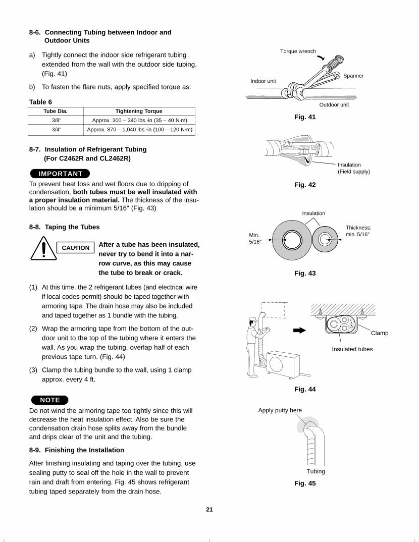
8-6. Connecting Tubing between Indoor andOutdoor Units
a) Tightly connect the indoor side refrigerant tubingextended from the wall with the outdoor side tubing.(Fig. 41)
b) To fasten the flare nuts, apply specified torque as:
Table 6
8-7. Insulation of Refrigerant Tubing (For C2462R and CL2462R)
To prevent heat loss and wet floors due to dripping ofcondensation, both tubes must be well insulated witha proper insulation material. The thickness of the insu-lation should be a minimum 5/16" (Fig. 43)
8-8. Taping the Tubes
(1) At this time, the 2 refrigerant tubes (and electrical wireif local codes permit) should be taped together witharmoring tape. The drain hose may also be includedand taped together as 1 bundle with the tubing.
(2) Wrap the armoring tape from the bottom of the out-door unit to the top of the tubing where it enters thewall. As you wrap the tubing, overlap half of eachprevious tape turn. (Fig. 44)
(3) Clamp the tubing bundle to the wall, using 1 clampapprox. every 4 ft.
Do not wind the armoring tape too tightly since this willdecrease the heat insulation effect. Also be sure thecondensation drain hose splits away from the bundleand drips clear of the unit and the tubing.
8-9. Finishing the Installation
After finishing insulating and taping over the tubing, usesealing putty to seal off the hole in the wall to preventrain and draft from entering. Fig. 45 shows refrigeranttubing taped separately from the drain hose.
NOTE
IMPORTANT
Indoor unit
Outdoor unit
Spanner
Torque wrench
Fig. 41
Insulation(Field supply)
Fig. 42
Fig. 43
Tube Dia. Tightening Torque
3/8" Approx. 300 – 340 lbs..in (35 – 40 N.m)
3/4" Approx. 870 – 1,040 lbs..in (100 – 120 N.m)
CAUTION After a tube has been insulated,never try to bend it into a nar-row curve, as this may causethe tube to break or crack.
02-291AirCon Final 12/11/02 2:46 PM Page 21

22
Manifold valve
Pressuregauge Lo Hi
Charge hose
Outdoor unit
Servicevalve
Wide tubeNarrow tube
Indoor unit
Nitrogen gas cylinder(In vertical standingposition)
Cap
Narrow tubeWide tube
Manifold valve
Pressuregauge Lo Hi
Nitrogen gas cylinder
9. Air Purging
Air and moisture remaining in the refrigerant systemhave undesirable effects as indicated below. Therefore,they must be purged completely.● pressure in the system rises● operating current rises● cooling (or heating) efficiency drops● moisture in the air may freeze and block capillary tub-
ing● water may lead to corrosion of parts in the refrigerant
system
■ Air Purging with a Vacuum Pump (for Test Run)
Check that each tube (both narrow and wide tubes)between the indoor and outdoor units have been proper-ly connected and all wiring for the test run has beencompleted. Remove the valve caps from both the wideand narrow service valves on the outdoor unit. Note thatboth narrow and wide tube service valves on the outdoorunit are kept closed at this stage.
Leak test
(1) With the service valves on the outdoor unit closed,remove the 1/4". flare nut and its bonnet on the widetube service valve. (Save them for reuse.)
(2) Attach a manifold valve (with pressure gauges) anddry nitrogen gas cylinder to this service port withcharge hoses.
(3) Pressurize the system to no more than 150 P.S.I.G.with dry nitrogen gas and close the cylinder valvewhen the gauge reading reaches 150 P.S.I.G. Then,test for leaks with liquid soap.
CAUTION Use a manifold valve for airpurging. If it is not available,use a stop valve for this pur-pose. The “Hi” knob of themanifold valve must always bekept closed.
Fig. 46
Fig. 47
02-291AirCon Final 12/11/02 2:46 PM Page 22

23
Manifold valve
Pressuregauge Lo Hi
Outdoor unit
Servicevalve
Wide tubeNarrow tube
Indoor unit
Vacuum pump
CAUTION
NOTE
To prevent nitrogen from enterthe refrigerant system in theliquid state, the top of thecylinder must be higher thanthe bottom when you pres-surize the system. Usually,the cylinder is used in avertical standing position.(Refer to the previous page.)
(4) Do a leak test of all joints of the tubing (bothindoor and outdoor) and both wide and narrowservice valves. Bubbles indicate a leak. Wipe offthe soap with a clean cloth after the leak test.
(5) After the system is found to be free of leaks,relieve the nitrogen pressure by loosening thecharge hose connector at the nitrogen cylinder.When the system pressure is reduced to normal,disconnect the hose from the cylinder.
Evacuation
(1) Attach the charge hose end described in thepreceding steps to the vacuum pump to evacuatethe tubing and indoor unit.Confirm that the “Lo” knob of the manifold valveis open. Then, run the vacuum pump. Theoperation time for evacuation varies with thetubing length and capacity of the pump. Thefollowing table shows the amount of time forevacuation:
The required time in the above table is calculatedbased on the assumption that the ideal (or target)vacuum condition is around 10 mmHg abs.
(2) When the desired vacuum is reached, close the“Lo” knob of the manifold valve and turn off thevacuum pump.
If tubing length is less than 50 ft.
45 minutes or more
If tubing length is longer than 50 ft.
90 minutes or more
Required time for evacuationwhen 30 gal/h vacuum pump is used
Vacuum pump
Cap
Narrow tubeWide tube
Manifold valve
Vacuumgauge Lo Hi
Fig. 48
Fig. 49
02-291AirCon Final 12/11/02 2:46 PM Page 23

24
Narrow tube
Hex wrench CLOSE OPEN
Wide tube
Outdoorunit
Wide tube
132 ft.
Narrow tube
Max. allowabletubing lengthat shipment
Requiredadditionalcharge
Indoorunit
Fig. 50
Fig. 51
Charging additional refrigerant
● Calculate the required amount of additional refrigerant
according to narrow tube length (see P. 3, Table 3).(Fig. 50)
● Use a balance (scale) to measure the refrigerant accu-
rately.
● After the required vacuum level is reached, charge liquid
refrigerant from the charge opening of the liquid-sidevalve. Valves must be closed at this time.
Note: If the additional refrigerant charge amount cannot allbe charged at once, charge the remaining refrigerantin gas form by using the wide tube service valve withthe system in Cooling mode at the time of test run.
● When the charging is completed, all valves must be fully
opened.
Finishing the job
(1) With a hex wrench, turn the narrow tube service valvestem counter-clockwise to fully open the valve. (Fig. 51)
(2) With a screwdriver, turn the wide tube service valvestem counter-clockwise to fully open the valve. (Fig. 51)
(3) Loosen the charge hose connected to the wide tubeservice port (1/4".) slightly to release the pressure,then remove the hose.
(4) Replace the 1/4". flare nut and its bonnet on the widetube service port and fasten the flare nut securely with anadjustable wrench or box wrench. This process is veryimportant to prevent gas from leaking from the system.
(5) Replace the valve caps at both wide and narrow ser-vice valves and fasten them securely.
This completes air purging with a vacuum pump. The airconditioner is now ready for a test run.
CAUTION Use a charging cylinderdesigned for use with R410A.
CAUTION When charging R410A, due to thehigh pressure be sure to careful-ly open the charging cylindervalve a little at a time.
CAUTIONTo avoid gas from leaking whenremoving the charge hose, makesure the stem of the wide tube isturned all the way out (“BACKSEAT” position).
02-291AirCon Final 12/11/02 2:46 PM Page 24

25
Fig. 52
ONOFFTEST
INDOOR UNIT
Operation Selector
10. Test Run
10-1. Preparing for Test Run
Before starting the air conditioner, check the follow-ing:
(1) Remove all loose matter from the cabinet especiallymetal filings, bits of wire, and clips.
(2) Connect the control wiring correctly and tighten all elec-trical connections.
(3) For “CL” models only:Connect the power to the unit for at least 5 hoursbefore starting the compressor. The bottom of the com-pressor should be warm to the touch and the crankcaseheater around the feet of the compressor should be hotto the touch.
(4) Open both the wide and narrow tube service valvesafter an air purge.
(5) Remove the transportation cardboard protection for theindoor fan.
10-2. Performing Test Run
(1) Locate the Operation Selector (on right side) by open-ing the air discharge grille on the indoor unit. (Fig. 52)
(2) Set the Operation Selector to the “Test” position. Theair conditioner will start running.
(3) Let the unit run for about 30 minutes and check thatthe unit operates normally.
(4) After the Test Run, be sure to reset the OperationSelector to the “ON” position for normal operation.The air conditioner continues to run.
(5) Referring to the Operatiing Instructions, select theCooling mode and press the ON / OFF operation but-ton on the remote control unit, to confirm remote con-trol unit operation.
Set the Operation Selector to the “ON” position.Otherwise the unit will stop or will not run correctly.
IMPORTANT
CAUTION Be careful since the fan willstart when performing Test Run.
02-291AirCon Final 12/11/02 2:46 PM Page 25

26
■ Basic Functions of the Service Valves
ActionNarrow Tube Service Wide Tube Service
Valve (3-Way) Valve (Ball Valve)
CLOSED CLOSED
Shipping andair purging
Fully FullyOPEN OPEN
Operating andtest runningthe air conditioner
Stem
O-ring
Narrow tube service valve Wide tube service valve
Service port (B)
Stem
Valve cap
O-ring
3-Way ValveC2462RCL2462R
02-291AirCon Final 12/11/02 2:46 PM Page 26

27
■ Pump Down
“Pump down” means collecting all refrigerant gas in thesystem back into the outdoor unit without losing any ofthe gas. Pump down is used when the unit is to bemoved or before servicing the refrigerant circuit.
Pump down procedure
(1) Connect the low pressure side (wide tube valve ser-vice port) charging hose of the manifold valve to theservice port (B) on the wide tube service valve.
(2) Using a hex wrench, turn the narrow tube servicevalve clockwise all the way to close the service valve.
(3) Press the operation button and start cooling opera-tion.
(4) When the low pressure gauge reading falls to 1 to 0.5 kg/cm2 (14.2 to 7.1 psi), fully close the wide tubevalve stem with a standard screwdriver. Then quicklystop the unit.When the pressure becomes 0.5 kg/cm
2or less, the
compressor stops by operation of the low-pressureswitch. Recover the remaining refrigerant using refrig-erant recovery equipment to protect the compressor.
(5) Disconnect all gauges and hoses, and replace thebonnets and the valve caps as they were previously.
(6) When the unit is transferred, after recovering therefrigerant in the unit, charge the specified amount ofrefrigerant.
CAUTION Be sure to carry out pump downwith the unit in Cooling mode.
02-291AirCon Final 12/11/02 2:46 PM Page 27

28
11. REFRIGERANT R410A: SPECIAL PRECAUTIONS WHEN INSTALLING UNIT
11-1. Characteristics of New Refrigerant R410A
11-1-1. What is New Refrigerant R410A?
R410A is a new refrigerant that contains two types of pseudo-non-azeotropic refrigerant mixture which do notadversely affect the earth’s ozone layer. Its refrigeration capacity and energy efficiency are about the same levelas the conventional refrigerant, R22.
11-1-2. Components (mixing proportions)
HFC32 (50%) / HFC125 (50%)
11-1-3. Characteristics
● Less toxic, more chemically stable refrigerant
● The composition of refrigerant R410A changes whether it is in a gaseous phase or liquid phase. Thus, when there is arefrigerant leak the basic performance of the air conditioner may be degraded because of a change in composition ofthe remaining refrigerant. Therefore, do not add new refrigerant. Instead, recover the remaining refrigerant with therefrigerant recovery unit. Then, after evacuation, totally recharge the specified amount of refrigerant with the newrefrigerant at its normal mixed composition state (in liquid phase).
● When refrigerant R410A is used, the composition will differ depending on whether it is in gaseous or liquid phase, andthe basic performance of the air conditioner will be degraded if it is charged while the refrigerant is in gaseous state.Thus, always charge the refrigerant while it is in liquid phase.
11-2. Checklist Before Installation
Use a clutch-type flare tool for R410A or the conventional flare tool. Note that sizes of the resultant flares differ betweenthese two tools. Where a conventional flare tool is used, make sure to observe A Specification (amount of protrusion).
● Size of flare
CAUTION Ether-type oil is used for compressor oil for R410A-type units, which is different fromthe mineral oil used for R22. Thus more attention to moisture prevention and fasterreplacement work compared with conventional models are required.
Diameter of tube (ø) DA Specification
Flare tool for R410A Conventional flare tool (for R22)
ø6.35 (1/4") 0 – 0.5 mm 1.0 – 1.5 mm
ø19.05 (3/4") 0 – 0.5 mm 1.0 – 1.5 mm
A
D
Flare tool for R410A
A
Conventional flare tool (R22)
D
● Flare nut: Because the new refrigerant R410A operates at 1.6 times higher pressure than the conventional refrigerant R22, the flare nuts that came with the unit must be used.
02-291AirCon Final 12/11/02 2:46 PM Page 28

29
● Tubing precautions
Refrigerant R410A is more easily affected by dust or moisture compared to R22, thus be sure to temporarily cover theends of the tubing with caps or tape prior to installation.
Never use 0.7mm-thick copper tubing or tubing which is less than 0.8mm in thickness, since air conditioners withR410A are subject to higher pressure than those using R22 and R407C.
● No addition of compressor oil for R410A
No additional charge of compressor oil is required.
● No use of refrigerant other than R410A
Never use a refrigerant other than R410A.
● If refrigerant R410A is exposed to fire
Through welding, etc., toxic gas may be released when R410A refrigerant is exposed to fire. Therefore, be sure toprovide ample ventilation during installation work.
● Caution in case of R410A leak
Check for possible leak points with the special leak detector for R410A. If a leak occurs inside the room, immediatelyprovide thorough ventilation.
Outer diameter: mm (inch) Tubing wall thickness: mm (inch)
Narrow tube ø6.35 (1/4") 0.8 (0.032)
Wide tube ø19.05 (3/4") 1.0 (0.042)
02-291AirCon Final 12/11/02 2:46 PM Page 29

30
11-3. Tools Specifically for R410A
● For servicing, use the following tools for R410A
● To prevent other refrigerants (R22, R407C) from being mistakenly charged to this unit, sizes of the service ports andflare nuts of the narrow tube service valve and wide tube service valve have been altered.
Tool Distinction Tool Name
● Gauge manifold
● Charging hose
● Gas leak detector
● Refrigerant cylinder
● Charging cylinder
● Refrigerant recovery unit
● Vacuum pump with anti-reverse flow (*1)
(Solenoid valve-installed type, which prevents oil from flowing back into the unit whenthe power is off, is recommended.)
● Vacuum pump (*2) … can be used if the following adapter is attached.
● Vacuum pump adapter (reverse-flow prevention adapter) (*3).
(Solenoid valve-installed adapter attached to a conventional vacuum pump.)
● Electronic scale for charging refrigerant
● Flare tool
● Bender
● Torque wrench
● Cutter, reamer
● Welding machine, nitrogen gas cylinder
Tools specifically for R410A
Tools which can be com-monly used for R22,R407C, and R410A
CAUTION ● The above tools specifically for R410A must not be used for R22 and R407C.Doing so will cause malfunction of the unit.
● For the above vacuum pump (*1, *2) and vacuum pump adapter (*3), those forR22-type units can be used for R407C-type. However, they must be used exclu-sively for R410A and never alternately with R22 and R407C.
02-291AirCon Final 12/11/02 2:46 PM Page 30

31
11-4. Charging Additional Refrigerant
11-4-1. When Tubes are Extended
● Observe the proper amount of refrigerant as stated in the installation manual that came with the indoor unit. Chargeadditional refrigerant in liquid state only.
11-5. Retro-Fitting Existing Systems
11-5-1. Use of Existing Units
● Never use new refrigerant R410A for existing units which use R22. This will cause the air conditioner to operateimproperly and may result in a hazardous condition.
11-5-2. Use of Existing Tubing
● If replacing an older unit that used refrigerant R22 with a R410A unit, do not use its existing tubing. Instead, com-pletely new tubing must be used.
CAUTION Never charge additional refrigerant if refrigerant is leaking from the unit.
02-291AirCon Final 12/11/02 2:46 PM Page 31


![Thermophysicalpropertiesofdryandhumidair ... · range of temperature and pressure. Data on gW of compressed humid air [7], humid nitrogen, humid argon, and humid carbon dioxide [9]](https://static.fdocuments.us/doc/165x107/5e626081cfea87225a37645c/thermophysicalpropertiesofdryandhumidair-range-of-temperature-and-pressure.jpg)