INSTALLATION INSTRUCTIONS SINGLE PACKAGE AIR CONDITIONERSK).pdf · SINGLE PACKAGE AIR CONDITIONERS...
24
Manual 2100-467K Page 1 of 24 SINGLE PACKAGE AIR CONDITIONERS MODELS PA13242-A PA13302-A PA13362-A PA13362-B PA13422-A PA13422-B PA13422-C PA13482-A PA13482-B PA13482-C PA13602-A PA13602-B PA13602-C INSTALLATION INSTRUCTIONS Manual : 2100-467K Supersedes: 2100-467J File: Volume II Tab 10 Date: 07-25-12 Bard Manufacturing Company, Inc. Bryan, Ohio 43506 Since 1914 . . . Moving ahead just as planned.
Transcript of INSTALLATION INSTRUCTIONS SINGLE PACKAGE AIR CONDITIONERSK).pdf · SINGLE PACKAGE AIR CONDITIONERS...

Manual 2100-467K Page 1 of 24
SINGLE PACKAGEAIR CONDITIONERS
MODELS PA13242-A PA13302-A PA13362-A PA13362-B PA13422-A PA13422-B PA13422-C PA13482-A PA13482-B PA13482-C PA13602-A PA13602-B
PA13602-C
INSTALLATION INSTRUCTIONS
Manual : 2100-467KSupersedes: 2100-467JFile: Volume II Tab 10Date: 07-25-12
Bard Manufacturing Company, Inc.Bryan, Ohio 43506
Since 1914 . . . Moving ahead just as planned.
Manual 2100-467K Page 2 of 24
CONTENTS
Getting Other Informations and Publications ......... 3
General InstructionsImportant ................................................................. 4Shipping Damage ..................................................... 4General ................................................................. 4Field Installed Heater Packages (Optional) .............. 4
InstallationLocation ............................................................... 10Slab Mounting ......................................................... 10Typical Installations .........................................10 & 13Condensate Drain Trap ........................................... 13Air Filters ............................................................... 13Wiring – Main Power ............................................... 14Wiring – 24V Low Voltage Control Circuit ............... 14Transformer Taps .................................................... 14Thermostats ............................................................ 14
Start Up and OperationGeneral ............................................................... 16Topping Off System Charge .................................... 16Safety Practices ...................................................... 16Start Up Notes ........................................................ 16Three Phase Scroll Compressor Start UpInformation .............................................................. 17Sequence of Operation ........................................... 17Indoor Blower Motor ................................................ 17Compressor Control Module ...........................17 & 18Adjustments ............................................................ 18Low Ambient Control ............................................... 18
Service and TroubleshootingService Hints ........................................................... 19Pressure Service Ports ........................................... 19R-410A Refrigerant Charge .................................... 19Fan Blade Settings ................................................. 19Pressure Tables ..............................................20 & 21Suction and Discharge Tube Brazing ...................... 22
Troubleshooting GE Blower Motors .................23-24
FiguresFigure 1A Unit Dimensions ....................................... 8Figure 1B Unit Dimensions ....................................... 9Figure 2 Slab Mounting at Ground Level .............. 11Figure 3 Airflow and Service Access Clearances ............................................. 11Figure 4 Elevated Mounting Platform ................... 12Figure 5 Condensate Drain Trap .......................... 13Figure 6 Low Voltage Wiring ................................ 15Figure 7 Low Ambient Control Wiring ................... 18Figure 8 Fan Blade Setting ................................... 19Figure 9 Brazing Diagram .................................... 22Figure 10 Motor Connections ................................. 23Figure 11 Wiring (Connections/Voltage) ................. 24
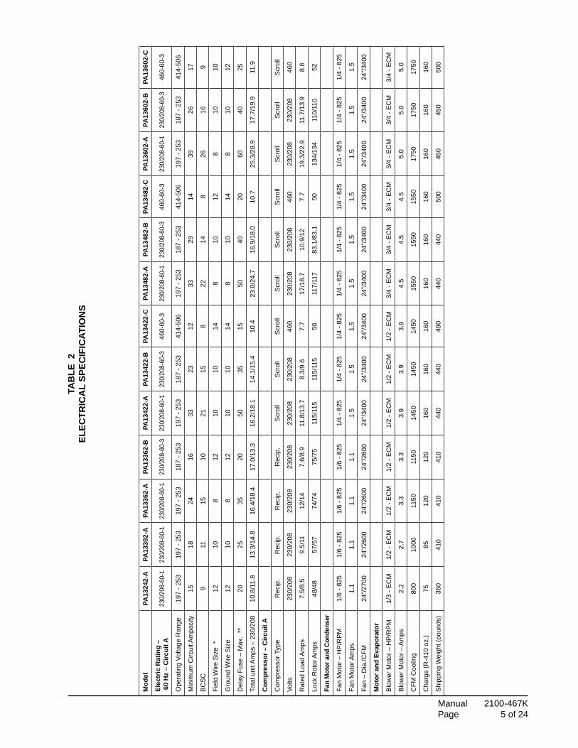
TablesTable 1 Rated CFM & ESP ................................... 4Table 2 Electrical Specifications ........................... 5Table 3 Opt. Field Installed Heater Packages ....... 6Table 4 Opt. Field Installed Elec. Heater .............. 7Table 5 Filter Requirements & Sizes ................... 13Table 6 Thermostat Wire Size ............................. 14Table 7 Wall Thermostats ................................... 14Table 8 Indoor Blower Performance ................... 19Table 9 Pressure Table ....................................... 20Table 10 Pressure Table ....................................... 21
Manual 2100-467K Page 3 of 24
Getting Other Information and Publications
These publications can help you install the air conditioner or heat pump. You can usually find these at your local library or purchase them directly from the publisher. Be sure to consult current edition of each standard.
National Electrical Code .......................ANSI/NFPA 70
Standard for the Installation ............... ANSI/NFPA 90A of Air Conditioning and Ventilating Systems
Standard for Warm Air ....................... ANSI/NFPA 90B Heating and Air Conditioning Systems
Load Calculation for ......................... ACCA Manual J Residential Winter and Summer Air Conditioning
Duct Design for Residential ............... ACCA Manual D Winter and Summer Air Conditioning and Equipment Selection
FOr mOre InFOrmatIOn, cOntact these PublIshers:
ACCA Air Conditioning Contractors of America 1712 New Hampshire Ave. N.W. Washington, DC 20009 Telephone: (202) 483-9370 Fax: (202) 234-4721
ANSI American National Standards Institute 11 West Street, 13th Floor New York, NY 10036 Telephone: (212) 642-4900 Fax: (212) 302-1286
ASHRAE American Society of Heating, Refrigerating, and Air Conditioning Engineers, Inc. 1791 Tullie Circle, N.E. Atlanta, GA 30329-2305 Telephone: (404) 636-8400 Fax: (404) 321-5478
NFPA National Fire Protection Association Batterymarch Park P.O. Box 9101 Quincy, MA 02269-9901 Telephone: (800) 344-3555 Fax: (617) 984-7057

Manual 2100-467K Page 4 of 24
General InstructIOns
ImPOrtantThe equipment covered in this manual is to be installed by trained, experienced service and installation technicians. All duct work, supply and return ducts, must be properly sized for the design airflow requirement of the equipment. ACCA is an excellent guide to proper sizing. All duct work or portions thereof not in the conditioned space should be properly insulated in order to both conserve energy and prevent condensation or moisture damage.
shIPPInG DamaGeUpon receipt of equipment, the carton should be checked for external signs of shipping damage. If damage is found, the receiving party must contact the last carrier immediately, preferably in writing, requesting inspection by the carrier’s agent.
GeneralThe refrigerant system is completely assembled and charged. All internal wiring is complete.
The unit is designed for use with or without duct work. Flanges are provided for attaching the supply and return ducts.
These instructions explain the recommended method to install the air cooled self-contained unit and the electrical wiring connections to the unit.
These instructions and any instructions packaged with any separate equipment required to make up the entire system should be carefully read before beginning the installation. Note particularly “Starting Procedure” and any tags and/or labels attached to the equipment.
While these instructions are intended as a general recommended guide, they do not supersede any national and/or local codes in any way. Authorities having jurisdiction should be consulted before the installation is made.
FIelD InstalleD heater PacKaGes (OPtIOnal)These packaged air conditioners are manufactured without supplementary electric heaters. Supplementary heaters are available for simple, fast field installation.
A separate power circuit is required for the supplementary heaters.
IMPORTANT: Refer to Table 1 when designing duct work for maximum available static pressure with heater installed.
Refer to data shown in Table 3 and 4 for proper application information on all available heater combinations and what units they can be used with. It also shows the applicable circuit ampacities, fuse size, and wire size for each heater combination.
table 1rateD cFm anD external statIc Pressure
(esP)
NOTE: ECM motors provide rated CFM up to 0.50 ESP
modelno.
rated cFm
recommendedAirflow Range
ratedesP
max.esP
PA1324 800 Note 0.18 0.50
PA1330 1000 Note 0.23 0.50
PA1336 1100 Note 0.23 0.50
PA1342 1450 Note 0.23 0.50
PA1348 1550 Note 0.28 0.50
PA1360 1750 Note 0.28 0.50
Manual 2100-467K Page 5 of 24
tab
le 2
elec
trIc
al
sPec
IFIc
atIO
ns
mod
elPa
1324
2-a
Pa13
302-
aPa
1336
2-a
Pa13
362-
bPa
1342
2-a
Pa13
422-
bPa
1342
2-c
Pa13
482-
aPa
1348
2-b
Pa13
482-
cPa
1360
2-a
Pa13
602-
bPa
1360
2-c
elec
tric
rat
ing
–
60
hz
– c
ircui
t a23
0/20
8-60
-123
0/20
8-60
-123
0/20
8-60
-123
0/20
8-60
-323
0/20
8-60
-123
0/20
8-60
-346
0-60
-323
0/20
8-60
-123
0/20
8-60
-346
0-60
-323
0/20
8-60
-123
0/20
8-60
-346
0-60
-3
Ope
ratin
g Vo
ltage
Ran
ge19
7 - 2
5319
7 - 2
5319
7 - 2
5318
7 - 2
5319
7 - 2
5318
7 - 2
5341
4-50
619
7 - 2
5318
7 - 2
5341
4-50
619
7 - 2
5318
7 - 2
5341
4-50
6
Min
imum
Circ
uit A
mpa
city
1518
2416
3323
1233
2914
3926
17
BC
SC
911
1510
2115
822
148
2616
9
Fiel
d W
ire S
ize
*12
108
1210
1014
810
128
1010
Gro
und
Wire
Siz
e12
108
1210
1014
810
148
1012
Del
ay F
use
– M
ax.
**20
2535
2050
3515
5040
2060
4025
Tota
l uni
t Am
ps –
230
/208
10.8
/11.
813
.3/1
4.8
16.4
/18.
417
.0/1
3.3
16.2
/18.
114
.1/1
5.4
10.4
23.0
/24.
716
.9/1
8.0
10.7
25.3
/28.
917
.7/1
9.9
11.9
com
pres
sor –
circ
uit a
Com
pres
sor T
ype
Rec
ip.
Rec
ip.
Rec
ip.
Rec
ip.
Scr
oll
Scr
oll
Scr
oll
Scr
oll
Scr
oll
Scr
oll
Scr
oll
Scr
oll
Scr
oll
Volts
230/
208
230/
208
230/
208
230/
208
230/
208
230/
208
460
230/
208
230/
208
460
230/
208
230/
208
460
Rat
ed L
oad
Am
ps7.
5/8.
59.
5/11
12/1
47.
6/8.
911
.8/1
3.7
8.3/
9.6
7.7
17/1
8.7
10.9
/12
7.7
19.3
/22.
911
.7/1
3.9
8.6
Lock
Rot
or A
mps
48/4
857
/57
74/7
475
/75
115/
115
115/
115
5011
7/11
783
.1/8
3.1
5013
4/13
411
0/11
052
Fan
mot
or a
nd c
onde
nser
Fan
Mot
or –
HP
/RP
M1/
6 - 8
251/
6 - 8
251/
6 - 8
251/
6 - 8
251/
4 - 8
251/
4 - 8
251/
4 - 8
251/
4 - 8
251/
4 - 8
251/
4 - 8
251/
4 - 8
251/
4 - 8
251/
4 - 8
25
Fan
Mot
or A
mps
1.1
1.1
1.1
1.1
1.5
1.5
1.5
1.5
1.5
1.5
1.5
1.5
1.5
Fan
– D
ia./C
FM24
”/270
024
”/260
024
”/260
024
”/260
024
”/340
024
”/340
024
”/340
024
”/340
024
”/340
024
”/340
024
”/340
024
”/340
024
”/340
0
mot
or a
nd e
vapo
rato
r
Blo
wer
Mot
or –
HP
/RP
M1/
3 - E
CM
1/2
- EC
M1/
2 - E
CM
1/2
- EC
M1/
2 - E
CM
1/2
- EC
M1/
2 - E
CM
3/4
- EC
M3/
4 - E
CM
3/4
- EC
M3/
4 - E
CM
3/4
- EC
M3/
4 - E
CM
Blo
wer
Mot
or –
Am
ps2.
22.
73.
33.
33.
93.
93.
94.
54.
54.
55.
05.
05.
0
CFM
Coo
ling
800
1000
1150
1150
1450
1450
1450
1550
1550
1550
1750
1750
1750
Cha
rge
(R-4
10 o
z.)
7585
120
120
160
160
160
160
160
160
160
160
160
Shi
ppin
g W
eigh
t (po
unds
)36
041
041
041
044
044
049
044
044
050
045
045
050
0

Manual 2100-467K Page 6 of 24
tab
le 3
OPt
IOn
al
FIel
D In
sta
lleD
hea
ter
Pa
cK
aG
es
On
lY t
O b
e u
seD
WIt
h t
he
mO
Del
s In
DIc
ateD
hea
ter P
acka
gem
odel
Volts
&
Phas
ePa
1324
2-a
Pa13
302-
aPa
1336
2-a
Pa13
362-
bPa
1342
2-a
Pa13
422-
bPa
1342
2-c
Pa13
482-
aPa
1348
2-b
Pa13
482-
cPa
1360
2-a
Pa13
602-
bPa
1360
2-c
EH
P32
3-A
0524
0/20
8-1
XX
X
EH
P32
3-A
1024
0/20
8-1
XX
X
EH
P32
3-A
1524
0/20
8-1
XX
EH
P32
3-B
0924
0/20
8-3
X
EH
P32
3-B
1524
0/20
8-3
X
EH
P51
3-A
0524
0/20
8-1
XX
X
EH
P51
3-A
1024
0/20
8-1
XX
X
EH
P51
3-A
1524
0/20
8-1
XX
X
EH
P51
3-B
0924
0/20
8-3
XX
X
EH
P51
3-B
1524
0/20
8-3
XX
X
EH
P51
3-C
0946
0-3
XX
X
EH
P51
3-C
1546
0-3
XX
X

Manual 2100-467K Page 7 of 24
tab
le 4
OPt
IOn
al
FIel
D In
sta
lleD
ele
ctr
Ic h
eate
r t
ab
le
IMP
OR
TAN
T:
Whi
le th
is e
lect
rical
dat
a is
pre
sent
ed a
s a
guid
e, it
is im
porta
nt to
ele
ctric
ally
con
nect
pro
perly
siz
ed fu
ses
and
co
nduc
tor w
ires
in a
ccor
danc
e w
ith th
e N
atio
nal E
lect
rical
Cod
e an
d al
l exi
stin
g lo
cal c
odes
.
Maximum
sizeofthetim
edelayfuseorH
ACRcircuitbreakerforprotectionoffieldwiringdevices.
B
ased
on
wire
sui
tabl
e fo
r 75°
C.
Oth
er w
iring
mat
eria
ls m
ust b
e ra
ted
for m
arke
d “M
inim
um C
ircui
t Am
paci
ty” o
r gre
ater
. B
ased
on
75°C
cop
per w
ire.
All
wiri
ng m
ust
conf
orm
to th
e N
atio
nal E
lect
ric C
ode
and
all l
ocal
cod
es.
These“M
inimum
CircuitA
mpacity”valuesaretobeusedforsizingthefieldpow
erconductors.R
efertotheNationalElectricCode(latestrevision),Article310forpow
er
cond
ucto
r siz
ing.
Hea
ter
Pac
kage
Mod
el N
o.
Uni
t Vol
ts
Pha
ses
Htr.
KW
& C
apac
ity@
240
Vol
tsH
tr. K
W &
Cap
acity
@ 2
08 V
olts
240/
208V
Htr.
Am
ps
Hea
ter
Inte
rnal
C
ircui
t B
reak
er
Circ
uit B
KW
BTU
HK
WB
TUH
No.
Fie
ld
Circ
uits
Min
.C
ircui
tA
mpa
city
Max.O
ver
Cur
rent
P
rote
ctio
n
Fiel
d P
ower
Wiri
ng
G
roun
dW
ireS
ize
EH
P32
3-A
0524
0/20
8-1
517,100
3.75
12,800
20.8
/18.
1
30/6
0
126
/23
30/2
510
/10
10
EH
P32
3-A
1024
0/20
8-1
1034,100
7.50
26,000
41.6
/36.
21
53/4
660
/50
6/8
10
EH
P32
3-A
1524
0/20
8-1
1551,200
11.2
538,400
62.5
/54.
11
79/6
880
/70
4/4
8
EH
P51
3-A
0524
0/20
8-1
517,100
3.75
12,800
20.8
/18.
1
30/6
0
126
/23
30/2
510
/10
10
EH
P51
3-A
1024
0/20
8-1
1034,100
7.50
26,000
41.6
/36.
21
53/4
660
/50
6/8
10
EH
P51
3-A
1524
0/20
8-1
1551,200
11.2
538,400
62.5
/54.
11
79/6
880
/70
4/4
8
EH
P32
3-B
0924
0/20
8-3
930,700
6.75
23,000
21.7
/18.
7N
one
128
/24
30/2
510
/10
10
EH
P32
3-B
1524
0/20
8-3
1551,200
11.2
538,400
36.2
/31.
21
46/3
950
/40
8/8
10
EH
P51
3-B
0924
0/20
8-3
930,700
6.75
23,000
21.7
/18.
7N
one
128
/24
30/2
510
/10
10
EH
P51
3-B
1524
0/20
8-3
1551,200
11.2
538,400
36.2
/31.
21
46/3
950
/40
8/8
10
EH
P51
3-C
0948
0-3
930,700
10.8
Non
e1
1415
1414
EH
P51
3-C
1548
0-3
1551,200
181
2830
1012

Manual 2100-467K Page 8 of 24
FIGure 1aDImensIOns OF unIts
Return openingDrain access
Supply opening
High voltage knockoutLow voltage knockout
access door
Control panel door
Heater package access panel
Compressor
Heater package knockout
A
E
C
D
LW
B
F
Condenser air
Condenser airintake grille
intake grille
access doorBlower motor
Condenser fan
G47 11/16"
H
Unit Dimension Chart
MIS-2142 A
A C B C H (height) L (length) W (width) D E F GPA/PH1324,1330,1336 5.875 32.875 13.875 32.875 26.25 53.25 38.125 23.25 1.125 1.375 35.625PA/PH1342,1348,1360 9.875 37.875 15.875 37.875 33.25 55.25 42.375 30.25 1.5 2.375 38.125
Unit Unit General DimensionsSupply Size Return Size Unit Overall Dimensions

Manual 2100-467K Page 9 of 24
FIGure 1bDImensIOns OF unIts
A B
C
D
FE
D
A
H
G
UNIT A B C D E F G H
PA/PH1324, 1330, 1336 7 3/16" 38 13/16" 36 3/4" 1 3/8" 33 5/8" 35 1/2" 18 3/16" 17 1/4"
PA/PH1342, 1348, 1360 8 3/16" 39 13/16" 36 3/4" 1 3/8" 37 3/4" 39 3/4" 18 1/2" 17 1/2"
MIS-3033

Manual 2100-467K Page 10 of 24
InstallatIOn
lOcatIOn
General
The unit must be located outside, or in a well ventilated area. It must not be in the space being heated or cooled. A sound absorbing material should be considered if the unit is to be installed in such a position or location that might cause transmission of sound or vibration to the living area or adjacent buildings.
slab mOuntInG
A minimum of 24 inches should be provided between the coil inlet and any building surfaces. Provide a minimum of three feet clearance on the service access side of the unit. See Figure 2.
tYPIcal InstallatIOns
1. rOOF mOunteD – The unit is mounted on a sturdy base on the roof of the building. Return air to the unit is brought through a single return grille (grilles with built-in filters are best since they enable easy access for filter changing). Return air ducts are attached to the lower section of the front panel. Supply air is brought from the unit to attic duct work or to a furred down hall. Supply air duct is attached to the top of the front panel.
CAUTION: All outdoor duct work must be thoroughly insulated and weatherproofed. All attic duct work must be thoroughly insulated. Two inch thick insulation with suitable vapor barrier is recommended for both outdoor and attic runs.
In roof top installation, as in all installations, the air conditioner must be level from side to side. However, the unit should have a pitch along the length to assure complete external drainage of precipitation and of defrost condensate.
2. craWl sPace – Duct work installed in crawl space must be well insulated and provided with a vapor barrier. In addition, the crawl space must be thoroughly ventilated and provided with a good vapor barrier as a ground cover. It is most desirable to install the unit will be outdoors rather than inside the crawl space, so that it will be readily accessible for service.
3. slab mOunteD at GrOunD leVel – This type installation is ideal for homes with a slab floor construction where a roof mounted unit is not desired. The supply and return duct work can be run through a furred closet space.
4. thrOuGh the Wall – This type installation requires a suitable framework to be fabricated capable of withstanding the unit weight. Normally the unit will be insulated so as to minimize supply and return duct work.

Manual 2100-467K Page 11 of 24
36" min.
24" min.
24" min.
The distance between1 inch clearance
Access
Air I
nlet
Comp-
Nearest Structure
Air Inlet
Supp
ly an
d Retu
rn D
ucts
Nearest Structure
Near
est S
tructu
re
Build
ing
Control Panel
AccessControl Panel
Access
Heater PackageAccess
Blower Service
and
ressor
Blower Motor
Heater Package
Blower
Compressor
from top.
units only).
Condenser fanand motor access
above fan.Leave 60" min.
Side
View
View
Top
between duct andany combustible
material if distancebetween outside
wall and unit is lessthan 3 feet (needed
on electric heat
MIS-2143 A
Mounting Slab
Ground Level
Package Unit
Supply Duct
from building
Return Duct
requirements.
outside wall and unitAir Outlet
varies with installation
1/4 inch per footslope away
Building
FIGure 2slab mOuntInG at GrOunD leVel
FIGure 3aIrFlOW anD serVIce access clearances

Manual 2100-467K Page 12 of 24
FIGure 4eleVateD mOuntInG PlatFOrm
Both legs must reston surface of platform
32°F or lower climate12" min. if in
48" min.
48" min.
32°F or lower climate12" min. if in
on surface of platformBoth legs must rest
Platform can be asshown or solid
Poured concrete,brick, or block
Metal frameMIS-2144 A
* AS REqUIRED
*
*
Manual 2100-467K Page 13 of 24
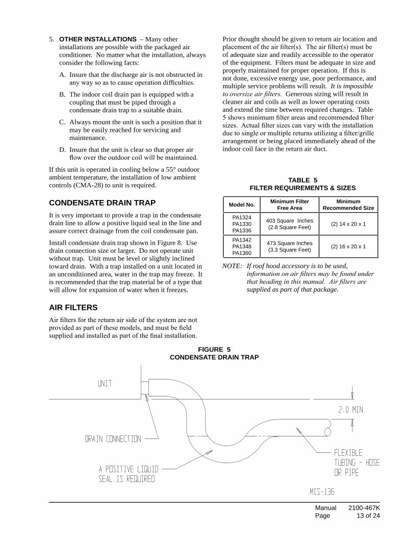
FIGure 5cOnDensate DraIn traP
5. Other InstallatIOns – Many other installations are possible with the packaged air conditioner. No matter what the installation, always consider the following facts:
A. Insure that the discharge air is not obstructed in any way so as to cause operation difficulties.
B. The indoor coil drain pan is equipped with a coupling that must be piped through a condensate drain trap to a suitable drain.
C. Always mount the unit is such a position that it may be easily reached for servicing and maintenance.
D. Insure that the unit is clear so that proper air flow over the outdoor coil will be maintained.
If this unit is operated in cooling below a 55° outdoor ambient temperature, the installation of low ambient controls (CMA-28) to unit is required.
cOnDensate DraIn traPIt is very important to provide a trap in the condensate drain line to allow a positive liquid seal in the line and assure correct drainage from the coil condensate pan.
Install condensate drain trap shown in Figure 8. Use drain connection size or larger. Do not operate unit without trap. Unit must be level or slightly inclined toward drain. With a trap installed on a unit located in an unconditioned area, water in the trap may freeze. It is recommended that the trap material be of a type that will allow for expansion of water when it freezes.
aIr FIltersAir filters for the return air side of the system are not provided as part of these models, and must be field supplied and installed as part of the final installation.
Prior thought should be given to return air location and placement of the air filter(s). The air filter(s) must be of adequate size and readily accessible to the operator of the equipment. Filters must be adequate in size and properly maintained for proper operation. If this is not done, excessive energy use, poor performance, and multiple service problems will result. It is impossible to oversize air filters. Generous sizing will result in cleaner air and coils as well as lower operating costs and extend the time between required changes. Table 5 shows minimum filter areas and recommended filter sizes. Actual filter sizes can vary with the installation due to single or multiple returns utilizing a filter/grille arrangement or being placed immediately ahead of the indoor coil face in the return air duct.
NOTE: If roof hood accessory is to be used, information on air filters may be found under that heading in this manual. Air filters are supplied as part of that package.
table 5FIlter requIrements & sIzes
model no. minimum FilterFree area
minimumrecommended size
PA1324PA1330PA1336
403 Square Inches(2.8 Square Feet) (2) 14 x 20 x 1
PA1342PA1348PA1360
473 Square Inches(3.3 Square Feet) (2) 16 x 20 x 1

Manual 2100-467K Page 14 of 24
table 6thermOstat WIre sIze
transFOrmer taPs230/208V, 1 phase and 3 phase equipment employ dual primary voltage transformers. All equipment leaves the factory wired on 240V tap. For 208V operation, reconnect from 240V to 208V tap. The acceptable operating voltage range for the 240 and 208V taps are: taP ranGe 240 253 – 216 208 220 – 187
NOTE: The voltage should be measured at the field power connection point in the unit and while the unit is operating at full load (maximum amperage operating condition).
WIrInG – maIn POWerRefer to the unit rating plate for wire sizing information and maximum fuse size. Each outdoor unit is marked with a “Minimum Circuit Ampacity”. This means that the field wiring used must be sized to carry that amount of current. If field installed heaters are added to the basic unit, a second separate power supply circuit will be required. The heater rating plate located adjacent to the basic unit rating plate will show the appropriate circuit ampacity fuse size, etc. (Also see “Electrical Specifications” on pages 5 & 7.) All models are suitable for connection with copper wire only. These instructions must be adhered to. Refer to the National Electrical Code for complete current carrying capacity data on the various insulation grades of wiring material.
The electrical specifications list fuse and wire sizes (75°F copper) for all models including the most commonly used heater sizes.
The unit rating plate lists a “Maximum Time Delay Fuse” or “HACR” type circuit breaker that is to be used with the equipment. The correct size must be used for proper circuit protection and also to assure that there will be no nuisance tripping due to the momentary high starting current of the compressor.
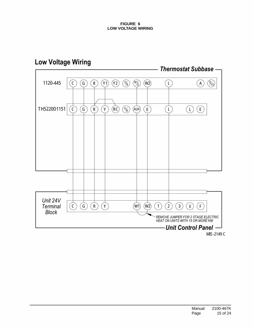
WIrInG – 24V lOW VOltaGe cOntrOl cIrcuItFive (5) wires should be run from thermostat subbase to the 24V terminal board in the unit. A five conductor, 18 gauge copper, color-coded thermostat cable is recommended. The connection points are shown in Figure 6.
thermOstatsSee specific wiring information for the different models, heater KWs, and voltages on unit and heating wiring diagrams.
IMPORTANT NOTE: Only the thermostats as shown above will work with this equipment. The thermostats and correct operation can be assured only by proper selection and application of these parts.
table 7Wall thermOstats
transformerVa Fla Wire
Gauge
maximumDistance In Feet
55 2.3
2018161412
4560100 160250
thermostat Predominant Features
8403-058(TH5220D1151)
2 stage Cool; 2 stage HeatElectronic Non-ProgrammableAutoorManualchangeover
8403-060(1120-445)
3 stage Cool; 3 stage HeatProgrammable/Non-Programmable ElectronicHPorConventionalAutoorManualchangeover
Manual 2100-467K Page 15 of 24
EY
1120-445
TH5220D1151
Low Voltage Wiring
L
2
C O
1
Unit Control Panel
BlockYC G R W1 W2 E F
Y1C G R W1OY2 W2 DA
ELAUXRG
EB
RC
3
L
B
Thermostat Subbase
Terminal
HEAT ON UNITS WITH 15 OR MORE KW
YO
Unit 24V
REMOVE JUMPER FOR 2 STAGE ELECTRIC
MIS-2149 C
FIGure 6lOW VOltaGe WIrInG
Manual 2100-467K Page 16 of 24
start uP
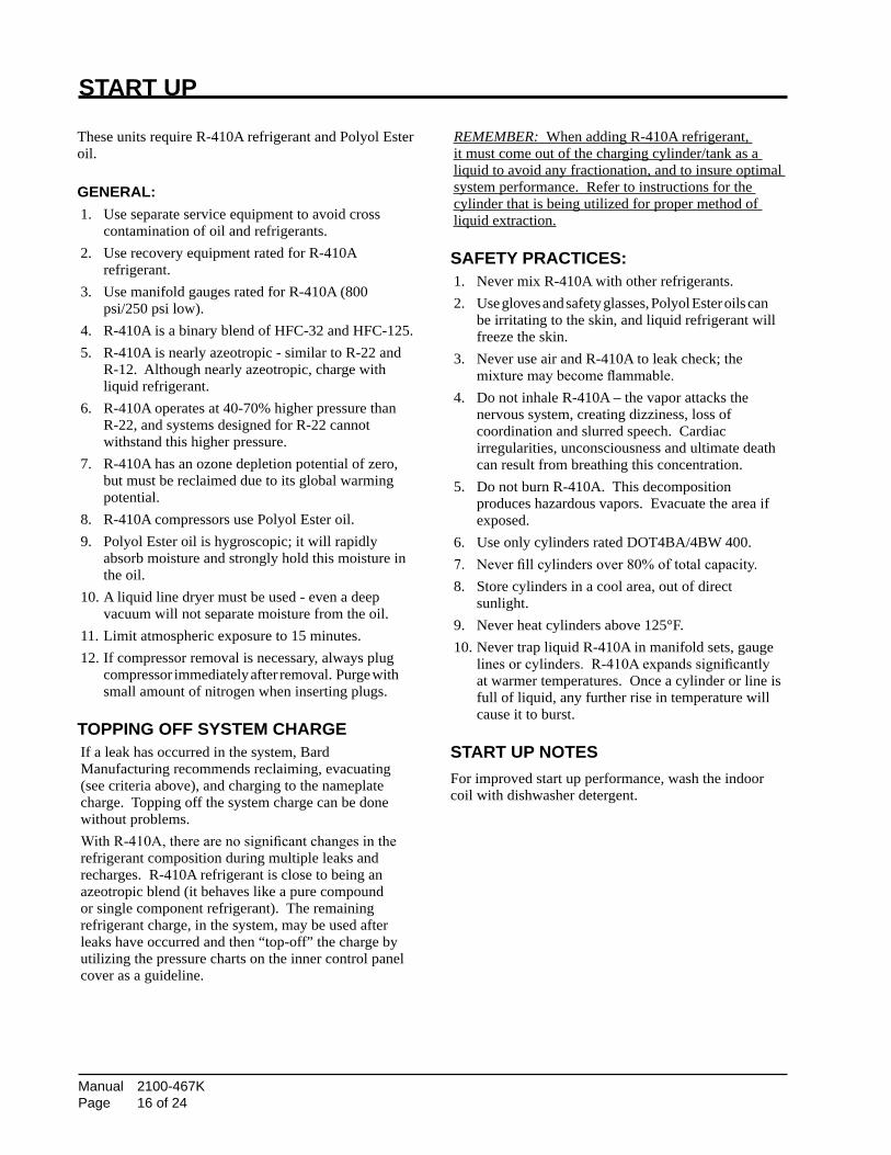
These units require R-410A refrigerant and Polyol Ester oil.
General:1. Use separate service equipment to avoid cross contamination of oil and refrigerants.2. Use recovery equipment rated for R-410A refrigerant.3. Use manifold gauges rated for R-410A (800 psi/250 psi low).4. R-410A is a binary blend of HFC-32 and HFC-125.5. R-410A is nearly azeotropic - similar to R-22 and R-12. Although nearly azeotropic, charge with liquid refrigerant.6. R-410A operates at 40-70% higher pressure than R-22, and systems designed for R-22 cannot withstand this higher pressure.7. R-410A has an ozone depletion potential of zero, but must be reclaimed due to its global warming potential.8. R-410A compressors use Polyol Ester oil.9. Polyol Ester oil is hygroscopic; it will rapidly absorb moisture and strongly hold this moisture in the oil.10. A liquid line dryer must be used - even a deep vacuum will not separate moisture from the oil.11. Limit atmospheric exposure to 15 minutes.12. If compressor removal is necessary, always plug compressor immediately after removal. Purge with small amount of nitrogen when inserting plugs.
tOPPInG OFF sYstem charGeIf a leak has occurred in the system, Bard Manufacturing recommends reclaiming, evacuating (see criteria above), and charging to the nameplate charge. Topping off the system charge can be done without problems.With R-410A, there are no significant changes in the refrigerant composition during multiple leaks and recharges. R-410A refrigerant is close to being an azeotropic blend (it behaves like a pure compound or single component refrigerant). The remaining refrigerant charge, in the system, may be used after leaks have occurred and then “top-off” the charge by utilizing the pressure charts on the inner control panel cover as a guideline.
REMEMBER: When adding R-410A refrigerant, it must come out of the charging cylinder/tank as a liquid to avoid any fractionation, and to insure optimal system performance. Refer to instructions for the cylinder that is being utilized for proper method of liquid extraction.
saFetY PractIces:1. Never mix R-410A with other refrigerants.2. Use gloves and safety glasses, Polyol Ester oils can be irritating to the skin, and liquid refrigerant will freeze the skin.3. Never use air and R-410A to leak check; the mixture may become flammable.4. Do not inhale R-410A – the vapor attacks the nervous system, creating dizziness, loss of coordination and slurred speech. Cardiac irregularities, unconsciousness and ultimate death can result from breathing this concentration.5. Do not burn R-410A. This decomposition produces hazardous vapors. Evacuate the area if exposed.6. Use only cylinders rated DOT4BA/4BW 400.7. Never fill cylinders over 80% of total capacity.8. Store cylinders in a cool area, out of direct sunlight.9. Never heat cylinders above 125°F.10. Never trap liquid R-410A in manifold sets, gauge lines or cylinders. R-410A expands significantly at warmer temperatures. Once a cylinder or line is full of liquid, any further rise in temperature will cause it to burst.
start uP nOtesFor improved start up performance, wash the indoor coil with dishwasher detergent.

Manual 2100-467K Page 17 of 24
three Phase scrOll cOmPressOr start uP InFOrmatIOn(Models PA13362-B; PA13422-B, -C; PA13482-B, -C; PA13602-B, -C)
All units with three phase scroll compressors are equipped with a three phase line monitor to prevent compressor damage due to phase reversal.
The phase monitor in this unit is equipped with two LED’s. If the “Y” signal is present at the phase monitor and phases are correct, the green LED will light.
If phases are reversed, the red fault LED will be lit and compressor operation is inhibited.
If a fault condition occurs, reverse tow of the supply leads to the unit. Do not reverse any of the unit factory wires as damage may occur.
sequence OF OPeratIOnblOWer OnlY – When the “Fan” switch on the room thermostat is placed in the “On” position (circuit R-G makes), the blower will energize and run until the “Fan” switch is placed back into the “Auto” position. This will allow for constant air circulation at a lower airflow during times when the unit is not in operation for cooling or heating.
cOOlInG – On a call for cooling from the room thermostat (circuit R-Y makes), the blower will energize (circuit R-G is automatic when R-Y makes) as well as the compressor, and outdoor fan motor. Note that if the “Fan” switch on the room thermostat is in the “On” position and the blower is already in operation, then the motor will ramp up to the required speed for cooling.
heatInG (1st stage) – On a call for heating from the room thermostat (circuit R-W1 makes), the blower will energize (circuit R-G is automatic when R-W1 makes). This will place the system into heating operation to maintain the thermostat set temperature. Note that if the “Fan” switch on the room thermostat is in the “On” position and the blower is already in operation, then the motor will ramp up to the required speed for heating.
heatInG (2nd stage) – If the operation of the 1st Stage electric heaters will not maintain the set room temperature, then the thermostat will call for additional heat to help maintain the set temperature. On a call for second stage heating from the room thermostat (circuit R-W2 makes), additional electric heaters will be energized if installed.
InDOOr blOWer mOtOrThese models feature a variable speed (ECM) motor providing high efficiency, low sound levels and soft start capabilities. The motor is self adjusting to provide the proper airflow rate at duct static pressures up to 0.50" WC without user adjustment or wiring changes.
On command from the wall thermostat the motor will start slowly and ramp up to full speed over a period of 10-15 seconds.
When the thermostat is satisfied the blower will operate for approximately 1 minute, and then slow down and stop.
cOmPressOr cOntrOl mODule The compressor control is an anti-short cycle/lockout timer with high and low pressure switch monitoring and alarm output.
aDJustable DelaY-On-maKe anD breaK tImer
On a call for compressor operation the delay-on-make period begins which will be 10% of the delay-on-break setting. When the delay-on-make is complete and the high pressure switch (and low pressure switch if employed) is closed, the compressor contactor is energized. Upon shutdown, the delay-on-break timer starts and prevents restart until the delay-on-break and delay-on-make periods have expired.
hIGh Pressure sWItch anD lOcKOut sequence (standard Feature)
If the high pressure switch opens, the compressor contactor will de-energize immediately. The lockout timer will go into a soft lockout and stay in soft lockout until the high pressure switch closes and the delay-on-make time has expired. If the high pressure switch opens again in this same operating cycle the unit will go into manual lockout condition and the alarm circuit will energize. Recycling the wall thermostat resets the manual lockout.
start uP anD OPeratIOn

Manual 2100-467K Page 18 of 24
lOW Pressure sWItch, bYPass, anD lOcKOut sequence (standard Feature)
If the low pressure switch opens for more that 120 seconds, the compressor contactor will de-energize and go into a soft lockout. Regardless the state of the low pressure switch, the contactor will reenergize after the delay-on-make time delay has expired. If the low pressure switch remains open or opens again for longer than 120 seconds the unit will go into manual lockout condition and the alarm circuit will energize. Recycling the wall thermostat resets the manual lockout.
alarm OutPut
Alarm terminal is output connection for applications where alarm signal is desired. This terminal is powered whenever compressor is locked out due to HPC or LPC sequences as described.
NOTE: Both high and low pressure switch controls are inherently automatic reset devices. The high pressure switch and low pressure switch cut out and cut in settings are fixed by specific air conditioner or heat pump unit model. The lockout features, both soft and manual, are a function of the Compressor Control Module.
aDJustments
aDJustable DelaY-On-maKe anD DelaY-On-breaK tImer
The potentiometer is used to select Delay-on-Break time from 30 seconds to 5 minutes. Delay-on-Make (DOM) timing on power-up and after power interruptions is equal to 2 minutes plus 10% of Delay-on-Break (DOB) setting:
0.5 minute (30 seconds) DOB = 123 second DOM 1.0 minute (60 seconds) DOB = 126 second DOM 2.0 minute (120 seconds) DOB = 132 second DOM 3.0 minute (160 seconds) DOB = 138 second DOM 4.0 minute (240 seconds) DOB = 144 second DOM 5.0 minute (300 seconds) DOB = 150 second DOM
FIGure 7lOW ambIent cOntrOl WIrInG
lOW ambIent cOntrOl
Optional Low Ambient ControlAn optional low ambient control is available for both factory and field installed options. The low ambient control is to be applied to the PA13 Series models when operation below 55° outdoor conditions are anticipated. Without this device, the evaporating pressure would fall off, and the indoor coil would ice over.The fan cycling control cycles the fan motor on, once the liquid refrigerant pressure reaches 350 psig, and off, once it has dropped to 225 psig. It will continue to cycle between these parameters depending on outdoor temperatures and the load/stage of the system.This cycling maintains a minimum liquid pressure affecting the minimum suction pressure. This effect insures an evaporating temperature that is slightly above the point of ice formation on the evaporator.This field installed option is Bard Part #CMA-28. See Figure 7.

Manual 2100-467K Page 19 of 24
Fan blaDe settInGsShown in Figure 8 are the correct fan blade setting dimensions for proper air delivery across the outdoor coil.
Any service work requiring removal or adjustment in the fan and/or motor area will require that the dimensions below be checked and blade adjusted in or out on the motor shaft accordingly.
MD-1417BC
serVIce anD trOubleshOOtInGserVIce hInts1. Caution homeowner to maintain clean air filters at
all times. Also, not to needlessly close off supply and return air registers. This reduces airflow through the system which shortens equipment service life as well as increasing operating costs.
2. Check all power fuses or circuit breakers to be sure that they are the correct rating.
3. Periodic cleaning of the outdoor coil to permit full and unrestricted airflow circulation is essential.
Pressure serVIce POrtsHigh and low pressure service ports are installed on all units so that the system operating pressures can be observed. Pressure tables can be found later in this manual covering all models on cooling cycle. It is imperative to match the correct pressure table to the unit by model number.
r-410areFrIGerant charGeThis unit was charged at the factory with the quantity of refrigerant listed on the serial plate. AHRI capacity and efficiency ratings were determined by testing with this refrigerant charge quantity.
The following pressure tables show nominal pressures for the units. Since many installation specific situations can affect the pressure readings, this information should only be used by certified technicians as a guide for evaluating proper system performance. They shall not be used to adjust charge. If charge is in doubt, reclaim, evacuate and recharge the unit to the serial plate charge.
table 8InDOOr blOWer PerFOrmance
1 MotorwilldeliverconsistentCFMthroughvoltagesupplyrangewithnodeterioration (197-253V for all 230/208V models).2 Continuous CFM is the total air being circulated during continuous (manual fan) mode.3 Will occur automatically with a call for “Y” for cooling mode operation.4 Will occur automatically with a call for “W1” for heating mode operation.
FIGure 8Fan blaDe settInG
model ratedesP
maxesP
continuous
Airflow
rated
cooling cFm
mrated
heating cFmPA1324 0.10 0.50 600 800 800
PA1330 0.15 0.50 750 1000 1000
PA1336 0.15 0.50 825 1100 1100
PA1342 0.20 0.50 925 1400 1400
PA1348 0.20 0.50 1025 1550 1550
PA1360 0.20 0.50 1150 1750 1750
3¼"

Manual 2100-467K Page 20 of 24
(con
tinue
d on
Pag
e 20
in t
able
11)
tab
le 9
Pres
sur
e ta
ble
cO
OlI
nG
Air
Tem
pera
ture
Ent
erin
g O
utdo
or C
oil D
egre
e F
LOW
SID
E P
RE
SS
UR
E +
4 P
SIG
HIG
H S
IDE
PR
ES
SU
RE
+10
PS
IG
TablesbaseduponratedCFM
(airflow
)acrosstheevaporatorcoil.
If in
corr
ect c
harg
e su
spec
ted
(mor
e th
an +4psigsuction,+10psigliquid),
itisrecommendedrefrigerantchargebereclaimed,systemevacuatedandchargedtoserialplatequantity.
Mod
elR
etur
n A
ir Te
mpe
ratu
reP
ress
ure
65°
70°
75°
80°
85°
90°
95°
100°
105°
110°
115°
120°
125°
PA13
24
75°
DB
62°
WB
Low
Sid
eH
igh
Sid
e12
523
812
726
212
928
613
131
013
333
413
535
813
738
213
840
714
043
214
245
714
348
214
550
714
753
2
80°
DB
67°
WB
Low
Sid
eH
igh
Sid
e13
424
413
626
913
829
314
031
814
234
314
436
714
639
214
841
815
044
315
146
915
349
415
552
015
754
6
85°
DB
72°
WB
Low
Sid
eH
igh
Sid
e14
425
314
627
814
830
415
132
915
335
515
538
015
740
615
943
216
145
916
348
516
551
216
753
816
956
5
PA13
30
75°
DB
62°
WB
Low
Sid
eH
igh
Sid
e12
624
612
826
713
128
913
331
013
533
213
735
313
937
414
140
214
342
914
545
714
848
415
051
215
253
9
80°
DB
67°
WB
Low
Sid
eH
igh
Sid
e13
525
213
727
414
029
614
231
814
434
014
736
214
940
015
141
215
344
015
646
915
849
716
052
516
255
3
85°
DB
72°
WB
Low
Sid
eH
igh
Sid
e14
526
114
828
415
030
615
332
915
535
215
837
516
039
716
342
716
545
616
748
517
051
417
254
317
457
3
PA13
36
75°
DB
62°
WB
Low
Sid
eH
igh
Sid
e12
524
712
727
112
829
513
032
013
234
413
336
913
539
313
641
813
844
313
946
814
149
414
251
9
80°
DB
67°
WB
Low
Sid
eH
igh
Sid
e13
425
313
627
813
730
313
932
814
135
314
237
814
441
314
642
914
745
514
948
015
050
615
253
2
85°
DB
72°
WB
Low
Sid
eH
igh
Sid
e14
426
214
628
814
831
414
933
915
136
515
339
115
541
715
744
415
847
116
049
716
252
416
355
1

Manual 2100-467K Page 21 of 24
tab
le 1
0Pr
essu
re
tab
le
LOW
SID
E P
RE
SS
UR
E +
4 P
SIG
HIG
H S
IDE
PR
ES
SU
RE
+10
PS
IG
TablesbaseduponratedCFM
(airflow
)acrosstheevaporatorcoil.
If in
corr
ect c
harg
e su
spec
ted
(mor
e th
an +4psigsuction,+10psigliquid),
itisrecommendedrefrigerantchargebereclaimed,systemevacuatedandchargedtoserialplatequantity.
cO
OlI
nG
Air
Tem
pera
ture
Ent
erin
g O
utdo
or C
oil D
egre
e F
Mod
elR
etur
n A
ir Te
mpe
ratu
reP
ress
ure
65°
70°
75°
80°
85°
90°
95°
100°
105°
110°
115°
120°
125°
PA13
42
75°
DB
62°
WB
Low
Sid
eH
igh
Sid
e12
624
212
826
512
928
813
131
113
233
413
435
713
638
013
740
913
843
714
046
614
149
414
252
314
355
1
80°
DB
67°
WB
Low
Sid
eH
igh
Sid
e13
524
813
727
213
829
514
031
914
234
314
336
614
440
214
641
914
844
814
947
815
150
715
253
615
356
5
85°
DB
72°
WB
Low
Sid
eH
igh
Sid
e14
525
714
728
114
930
615
133
015
235
515
437
915
640
415
743
415
946
416
049
416
252
516
355
516
558
5
PA13
48
75°
DB
62°
WB
Low
Sid
eH
igh
Sid
e12
523
912
726
312
828
712
931
113
033
513
235
913
338
313
441
013
643
813
746
513
949
214
052
014
254
7
80°
DB
67°
WB
Low
Sid
eH
igh
Sid
e13
424
513
527
013
729
413
831
913
934
414
136
814
240
414
442
114
544
914
747
714
850
515
053
315
256
1
85°
DB
72°
WB
Low
Sid
eH
igh
Sid
e14
425
414
527
914
730
514
833
015
035
615
138
115
340
715
443
615
646
515
849
416
052
316
155
216
358
1
PA13
60
75°
DB
62°
WB
Low
Sid
eH
igh
Sid
e12
422
412
525
412
628
512
731
512
834
512
937
513
040
613
143
113
145
613
248
013
350
513
453
0
80°
DB
67°
WB
Low
Sid
eH
igh
Sid
e13
323
013
426
113
529
213
632
313
735
413
838
513
842
614
044
214
146
714
149
314
251
814
354
4
85°
DB
72°
WB
Low
Sid
eH
igh
Sid
e14
323
814
427
014
530
214
633
414
736
614
839
814
943
115
045
715
148
415
251
015
353
715
456
3
Manual 2100-467K Page 22 of 24
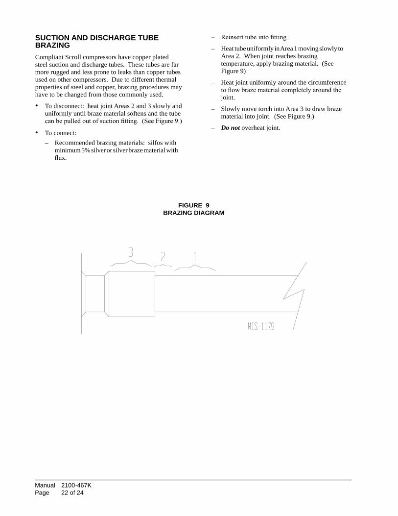
suctIOn anD DIscharGe tube brazInGCompliant Scroll compressors have copper plated steel suction and discharge tubes. These tubes are far more rugged and less prone to leaks than copper tubes used on other compressors. Due to different thermal properties of steel and copper, brazing procedures may have to be changed from those commonly used.
• To disconnect: heat joint Areas 2 and 3 slowly and uniformly until braze material softens and the tube can be pulled out of suction fitting. (See Figure 9.)
• To connect: – Recommended brazing materials: silfos with
minimum 5% silver or silver braze material with flux.
– Reinsert tube into fitting.
– Heat tube uniformly in Area 1 moving slowly to Area 2. When joint reaches brazing temperature, apply brazing material. (See Figure 9)
– Heat joint uniformly around the circumference to flow braze material completely around the joint.
– Slowly move torch into Area 3 to draw braze material into joint. (See Figure 9.)
– Do not overheat joint.
FIGure 9brazInG DIaGram

Manual 2100-467K Page 23 of 24
FIGure 10
NOTE: Bard Models PA13242; PA13302; PA13362-A, -B; PA13422-A, -B, -C; PA13482-A, -B, -C; PA13602-A, -B, -C contain the X13-Series Motors.
trOubleshOOtInG Ge x13-serIes ecm2.3™ mOtOrs
If the Motor is Running 1. It is normal for the motor to rock back and forth on start up. Do not replace the motor if this is the only problem identified. 2. If the system is excessively noisy, does not appear to change speeds in response to a demand (Heat, Cool, Other), or is having symptoms during the cycle such as tripping limit or freezing coil, check the following: a. Wait for programmed delays to time out. b. Ensure that the motors control inputs are wired to the factory supplied wiring diagram to insure motor is getting proper control signals and sequencing. c. Remove the filter and check that all dampers, registers, and grilles are open and free flowing. If removing the filters corrects the problem, clean or replace with a less restrictive filter. Also check and clean the blower wheel or coil as necessary. d. Check the external static pressure (total of both supply and return) to insure that you are within the ranges as listed on the unit serial plate. If higher than allowed, additional duct work is needed.
e. If the motor does not shut off at the end of the cycle, wait for any programmed delays to time out (no more than 90 seconds). Also make sure that there is no call for “Continuous Fan” on the “G” terminal. f. If the above diagnostics do not solve the problem, confirm the voltage checks in the next section below, then continue with the “Model X13 Communication Diagnostics”.
If the Motor is Not Running 1. Check for proper high voltage and ground at the (L/L1) (G) (N/L2) connections at the motor (see Figure 10). Correct any voltage issues before proceeding to the next step. The X13 Motor is voltage specific. Only the correct voltage should be applied to the proper motor. Input voltage within plus or minus 10% of the nominal 230 VAC is acceptable. 2. If the motor has proper high voltage and ground at the (L/L1) (G) (N/L2) connections, then continue with the “Model X13 Communication Diagnostics”.
Manual 2100-467H
Page 22 of 23
FIGURE 10
↓ ↓
NOTE: Bard Models PA13242; PA13302; PA13362-A, -B; PA13422-A, -B, -C; PA13482-A, -B, -C; PA13602-A, -B, -C
contain the X13-Series Motors.
TROUBLESHOOTING GE X13-SERIES ECM2.3™ MOTORS
If the Motor is Running
1. It is normal for the motor to rock back and forth on start up.
Do not replace the motor if this is the only problem identified.
2. If the system is excessively noisy, does not appear to change
speeds in response to a demand (Heat, Cool, Other), or is having
symptoms during the cycle such as tripping limit or freezing coil,
check the following:
a. Wait for programmed delays to time out.
b.Ensure that the motors control inputs are wired to the factory
supplied wiring diagram to insure motor is getting proper
control signals and sequencing.
c. Remove the filter and check that all dampers, registers, and
grilles are open and free flowing. If removing the filters
corrects the problem, clean or replace with a less restrictive
filter. Also check and clean the blower wheel or coil as
necessary.
d.Check the external static pressure (total of both supply and
return) to insure that you are within the ranges as listed on the
unit serial plate. If higher than allowed, additional duct work
is needed.
e. If the motor does not shut off at the end of the cycle, wait for
any programmed delays to time out (no more than 90
seconds). Also make sure that there is no call for
“Continuous Fan” on the "G" terminal.
f. If the above diagnostics do not solve the problem, confirm the
voltage checks in the next section below, then continue with
the “Model X13 Communication Diagnostics”.
If the Motor is Not Running
1. Check for proper high voltage and ground at the (L/L1) (G) (N/
L2) connections at the motor (see Figure 10). Correct any voltage
issues before proceeding to the next step. The X13 Motor is voltage
specific. Only the correct voltage should be applied to the proper
motor. Input voltage within plus or minus 10% of the nominal 230
VAC is acceptable.
2. If the motor has proper high voltage and ground at the (L/L1)
(G) (N/L2) connections, then continue with the “Model X13
Communication Diagnostics”.
L2 LINE
POWER
EARTH
GROUND
L1 LINE
POWER
NOTE: MOTOR IS CONSTANTLY
POWERED BY LINE VOLTAGE
Manual 2100-467K Page 24 of 24
FIGure 11
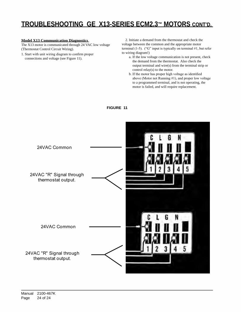
trOubleshOOtInG Ge x13-serIes ecm2.3™ mOtOrs cOnt’D.
Model X13 Communication Diagnostics The X13 motor is communicated through 24 VAC low voltage (Thermostat Control Circuit Wiring).1. Start with unit wiring diagram to confirm proper connections and voltage (see Figure 11).
2. Initiate a demand from the thermostat and check the voltage between the common and the appropriate motor terminal (1-5). (“G” input is typically on terminal #1, but refer to wiring diagram!) a. If the low voltage communication is not present, check the demand from the thermostat. Also check the output terminal and wire(s) from the terminal strip or control relay(s) to the motor. b. If the motor has proper high voltage as identified above (Motor not Running #1), and proper low voltage to a programmed terminal, and is not operating, the motor is failed, and will require replacement.
Manual 2100-467H
Page 23 of 23
FIGURE 11
TROUBLESHOOTING GE X13-SERIES ECM2.3™ MOTORS CONT’D.
Model X13 Communication Diagnostics
The X13 motor is communicated through 24 VAC low voltage
(Thermostat Control Circuit Wiring).
1. Start with unit wiring diagram to confirm proper
connections and voltage (see Figure 11).
2. Initiate a demand from the thermostat and check the
voltage between the common and the appropriate motor
terminal (1-5). ("G" input is typically on terminal #1, but
refer to wiring diagram!)
a. If the low voltage communication is not present, check
the demand from the thermostat. Also check the
output terminal and wire(s) from the terminal strip or
control relay(s) to the motor.
b. If the motor has proper high voltage as identified
above (Motor not Running #1), and proper low voltage
to a programmed terminal, and is not operating, the
motor is failed, and will require replacement.
24VAC "R" Signal through
thermostat output.
24VAC Common
24VAC Common
24VAC "R" Signal through
thermostat output.