Installation instructions Roxtec RM BG™ B modules · Installation instructions Roxtec RM BG™ B...
8
Installation instructions Roxtec RM BG ™ B modules 1 Clean the empty frame from paint, dirt etc. to secure good electrical conductivity. Installation BG B BG B BG B BG B BG B BG B BG B BG B BG B BG B BG B 2 1 3 4 5 6 1. Multidiameter™ – adapts to ca- bles and pipes of different sizes through removable layers 2. Bonding/grounding braid 3. Environmental side 4. Conductors 5. Cable armor 6. Outer jacket Environmental side Termination/interior side Cable position in a RM BG B module 2 Remove the core and fold out the braid on modules that are to hold cable/pipe. 3 Adapt outer layers to cable/pipe on both module halves. 4 Adapt inner layers to cable screen/ armor/pipe on both module halves. 5 Fold the braid tightly inside the module. Integrated environmental sealing system for bonding and grounding applications. For use with armored/shielded jacketed cables including smooth and corrugated cables such as interlocked and continuous welded metal clad cables or wired and braided cables. For approvals, see www.roxtec.com. Roxtec RM BG ™ B module Please see page 4 - 8 for cable preparation alternatives NOTE: The halves may not differ by more than one layer.
Transcript of Installation instructions Roxtec RM BG™ B modules · Installation instructions Roxtec RM BG™ B...

Installation instructions Roxtec RM BG™ B modules
1
Clean the empty frame from paint, dirt etc. to secure good electrical conductivity.
Installation
BG B BG B
BG BBG B
BG BBG B
BG BBG B
BG B
BG B
BG B
BG B BG B
BG BBG B
BG BBG B
BG BBG B
BG B
BG B
BG B
21
3
4
5
6
1. Multidiameter™ – adapts to ca-bles and pipes of different sizes through removable layers
2. Bonding/grounding braid3. Environmental side4. Conductors5. Cable armor6. Outer jacket
Environmental side Termination/interior side
Cable position in a RM BG B module
2
Remove the core and fold out the braid on modules that are to hold cable/pipe.
3
Adapt outer layers to cable/pipe on both module halves.
4
Adapt inner layers to cable screen/armor/pipe on both module halves.
5
Fold the braid tightly inside the module.
Integrated environmental sealing system for bonding and grounding applications. For use with armored/shielded jacketed cables including smooth and corrugated cables such as interlocked and continuous welded metal clad cables or wired and braided cables. For approvals, see www.roxtec.com.
Roxtec RM BG™ B module
Please see page 4 - 8 for cable preparation alternatives
NOTE: The halves may not differ by more than one layer.

7
Lubricate the frame on the areas that will be in contact with the rubber of the modules. Make sure to get lubricant into the corners. Avoid excess lubricant on areas in contact with the braid.
11
Before inserting the final row of modules, insert two stayplates together.
8
Lubricate all modules for the frame thoroughly, both the inside and the outside surfaces. Avoid excess lubricant on the braid.
12
Separate the two stayplates and insert the final row of modules between the stayplates. Drop the upper stayplate on top of the modules.
9
Insert the module halves directly on top of the cables. Do not slide them in.
10
Insert a stayplate on top of every finished row of modules. Make sure the stayplate is clean.
For temporary compression of the last module rows, use the S or L tool to keep the cables in position.
13
Pre-compress by using Roxtec pre-compression wedge.
Lubricate the wedge on all sides, except front and back, and insert the wedge on top of the frame (standard position).
14
All modules should be of the same type in each opening and turned in the same direction. Please note the markings on the face of the module.
Markings on module
6
Achieve a 0.1-1.0 mm gap be-tween the two halves when held against the cable/pipe.
0.1-1.0 mm(0.004-0.039")
Optional
BG B
BG B
BG B
BG B
BG BBG B
BG B
BG B

Note
DisassemblyReverse order
Packing spaceFrame sizes 2, 4, 6 and 8 accom-modate the following height of mo-dules: 60 mm, 120 mm, 180 mm and 240 mm. As example shows for frame size 6, the 180 mm can be the result of 4 rows of RM 40 plus one row of RM 20.
■■ For optimum reliability, wait 24 hours or longer after installation before exposing the cables/pipes to strain or pressure.
■■ Cables shall pass straight through the frame.
■■ Where adequate bonding/grounding cannot be established via the surface the frame is mounted on, an additional ground con
ductor has to be installed. The final complete bonding/grounding installation has to comply with applicable codes and regulations.
■■ To simplify installation in frames with more than one opening, fill all openings before tightening the compression units.
■■ Anti-short bushing is not supplied by Roxtec.
16
Attach the Wedge Clip to the wedge bolts to check that the wedge is properly tightened.
15
Tighten the screws until full stop, approx. 20 Nm (15 ft.lb.).
Sizing chart
RM 20w40 BG B 0+ 3.5-16.5 0+0.138-0.650 4* 11*
RM 30 BG B 0+ 10.0-25.0 0+0.394-0.984 13 6
RM 40 10-32 BG B 0+ 9.5-32.5 0+0.374-1.280 21 4
RM 60 20-54 BG B 0+ 24.0-54.0 0+0.945-2.126 42 1
RM 90 BG B woc** 48.0-71.0 1.890-2.795 42 1
RM 120 BG B woc** 67.5-99.0 2.657-3.898 42 1
For cable/pipe outer diameter Total braid cross- Approx. Module a-b (mm) a-b (in) section sq mm Eqv. AWG
* Per cable. ** woc = without core

1
On the cable, mark where outer sheath is to be removed.
2
Remove the outer sheath with a tool of your choice. Make sure not to damage the cable armor. Remove any protection tape or plastics.
Preparation of metal clad and Teck cableFinishing of interlocked and continuous welded armor.
3
On the armor, mark with a pen the length that will match the braid sec-tion of the RM BG B™. Make sure that the armor is visible outside the module after installation.
L
4
Cut the cable armor at the mark with a tool of your choiche. Make sure not to damage the conduc-tors.
L
5
When required for inner conductor protection, fit an anti-short bushing or similar at the end cut of the cable armor.
L
6
Make sure that the armor extends beyond the edge of the module and that the anti-short bushing is in place where applicable.

5
Pull the piece of cable sheath away to cover the end of the armor. The exposed armor shall accomodate both the braid and the remaining rubber of the module.
6
Make sure that the piece of cable sheat is completely outside the module.
4
Cut the armor at the mark with a tool of your choice. Make sure not to damage the conductors.
Preparation of SWA cable alternative 1Finishing the end of cable armor with piece of cable sheath.
1
On the cable, make two marks where outer sheath is to be cut.
L
2
Cut the outer sheath at the two marks with a tool of your choice. Make sure not to damage the cable armor. Remove excess sheath.
L
L
3
Mark where the armor is to be cut.
L
Approx. 12 mm (½")
L
Please see next page for alternative 2
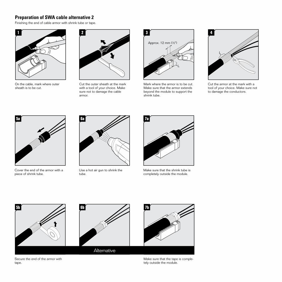
5a
Cover the end of the armor with a piece of shrink tube.
5b
Secure the end of the armor with tape.
6b
6a
Use a hot air gun to shrink the tube.
Preparation of SWA cable alternative 2Finishing the end of cable armor with shrink tube or tape.
1
On the cable, mark where outer sheath is to be cut.
2
Cut the outer sheath at the mark with a tool of your choice. Make sure not to damage the cable armor.
4
Cut the armor at the mark with a tool of your choice. Make sure not to damage the conductors.
L
7a
Make sure that the shrink tube is completely outside the module.
7b
Make sure that the tape is comple-tely outside the module.
Alternative
3
Mark where the armor is to be cut. Make sure that the armor extends beyond the module to support the shrink tube.
L
Approx. 12 mm (½")

4
Cut the braid at the mark with a tool of your choice. Make sure not to damage the conductors.
Preparation of braided cable alternative 1Finishing the end of cable armor with piece of cable sheath.
L
1
On the cable, make two marks where outer sheath is to be cut.
L
2
Cut the outer sheath at the two marks with a tool of your choice. Make sure not to damage the cable braid. Remove excess sheath.
L
3
Mark where the braid is to be cut.
L
Approx. 12 mm (½")
5
Pull the piece of cable sheath away to cover the end of the armor. The exposed armor shall accomodate both the braid and the remaining rubber of the module.
6
Make sure that the piece of cable sheath is completely outside the module.
Please see next page for alternative 2

Roxtec ®
and Multidiam
eter ® are registered tradem
arks of Roxtec in S
weden and/or other countries.
DISCLAIMER”The Roxtec cable entry sealing system (”the Roxtec system”) is a modular-based system of sealing products consisting of different components. Each and every one of the components is necessary for the best performance of the Roxtec system. The Roxtec system has been certified to resist a number of different hazards. Any such certification, and the ability of the Roxtec system to resist such hazards, is dependent on all components that are installed as a part of the Roxtec system. Thus, the certification is not valid and does not apply unless all components installed as part of the Roxtec system are manufactured by or under license from Roxtec (“authorized manufacturer”). Roxtec gives no performance guarantee with respect to the Roxtec system, unless (I) all components installed as part of the Roxtec system are manufactured by an authorized manufacturer and (II) the purchaser is in compliance with (a), and (b), below.
(a) During storage, the Roxtec system or part thereof, shall be kept indoors inits original packaging at room temperature.
(b) Installation shall be carried out in accordance with Roxtec installation instructions in effect from time to time.
The product information provided by Roxtec does not release the purchaser of the Roxtec system, or part thereof, from the obligation to independently determine the suitability of the products for the intended process, installation and/or use.
Roxtec gives no guarantee for the Roxtec system or any part thereof and assumes no liability for any loss or damage whatsoever, whether direct, indirect, consequential, loss of profit or otherwise, occurred or caused by the Roxtec systems or installations containing components not manufactured by an authorized manufacturer.
Roxtec expressly excludes any implied warranties of merchantability and fitness for a particular purpose and all other express or implied representations and warranties provided by statute or common law. User determines suitability of the Roxtec system for intended use and assumes all risk and liability in connection therewith. In no event shall Roxtec be liable for consequential, punitive, special, exemplary or incidental damages.”
Article num
ber: AS
S2011002501
Docum
ent number: A
SS
2011002501 version C
Please return to first page to complete
the installation
5a
Cover the end of the braid with a piece of shrink tube.
5b
Secure the end of the armor with tape.
6b
6a
Use a hot air gun to shrink the tube.
Preparation of braided cable alternative 2Finishing the end of cable braid with shrink tube or tape.
1
On the cable, mark where outer sheath is to be cut.
2
Cut the outer sheath at the mark with a tool of your choice. Make sure not to damage the cable braid.
4
Cut the braid at the mark with a tool of your choice. Make sure not to damage the conductors.
L
7a
Make sure that the shrink tube is completely outside the module.
7b
Make sure that the tape is completely outside the module.
Alternative
3
Mark where the braid is to be cut. Ensure that the braid extends beyond the module to support the shrink tube.
L
Approx. 12 mm (½")
Roxtec International AB Box 540, 371 23 Karlskrona, SWEDEN PHONE +46 455 36 67 00, FAX +46 455 820 12 EMAIL [email protected], www.roxtec.com