INSTALLATION INSTRUCTIONS - Ride Riteriderite.com/-/media/www/riderite/files/Install Manuals...3...
16
INSTALLATION INSTRUCTIONS riderite.com 2528 4-16
Transcript of INSTALLATION INSTRUCTIONS - Ride Riteriderite.com/-/media/www/riderite/files/Install Manuals...3...
INSTALLATION INSTRUCTIONS
riderite.com
2528
4-16

riderite.com1
! IMPORTANTPLEASE DON’T HURT YOURSELF, YOUR KIT OR YOUR VEHICLE. TAKE A MINUTE TO READ THIS IMPORTANT INFORMATION.
This kit is to be used on a pickup truck only, and DOES NOT INCREASE YOUR VEHICLE’S MAXIMUM LOAD.
SAFE INSTALLATIONPlease take all safety precautions during installation. A hydraulic jack can fail, and if that happens, you can be seriously hurt, or worse, if you are relying on it to hold up the vehicle. If you use a hydraulic jack, secure jack stands in the appropriate locations and chock any tires still touching the ground.
Wear safety glasses or goggles. Your eyes may be lower than some parts and pieces, and you don’t want to lose an eye.
Remove the possibility of any electrical issues by disconnecting the negative battery cable.
KIT CLEARANCEThere must be a minimum of 1/2" clearance around all installed components when the Air Springs are inflated and under a load. The Air Springs must flex and expand during operation, so the clearance keeps the kit from rubbing against parts of the vehicle.
VEHICLE GVWRNEVER exceed the maximum load recommended by the vehicle manufacturer (GVWR). The GVWR can be found in your vehicle’s owner’s manual or on the data plate on the driver’s side door. Consult your local dealership for additional GVWR specifications.
INFLATING THE AIR SPRINGSWhen inflating Air Springs, add air pressure in small quantities, checking air pressure frequently. The Air Springs have much less air volume than a tire, so they inflate much more quickly.
PRESSURE TO LOADThe Air Springs will support approximately 50 lbs. of load for each PSI of inflation pressure (per pair). For example, 50 PSI of inflation pressure will support a load of 2500 lbs. per pair of Air Springs.
APPROPRIATE AIR PRESSUREFor best ride, use only enough air pressure in the Air Springs to level the vehicle when viewed from the side (front to rear). This will vary, depending on the load, location of the load, condition of the existing suspension, and personal preference.
OPTIONAL T-FITTINGThis kit includes Inflation Valves and Air Line Tube for each Air Spring, allowing you to compensate for unbalanced loads. If you prefer a single Inflation Valve system to provide equal pressure to both Air Springs, your dealer can supply the optional “T” fitting (Part # 3025 or WRI-760-3461 retail pack).
ONCE INSTALLED SUCCESSFULLY, FOLLOW THESE PRESSURE REQUIREMENTS FOR THE AIR SPRINGS:
2528 Installation Instructions 2
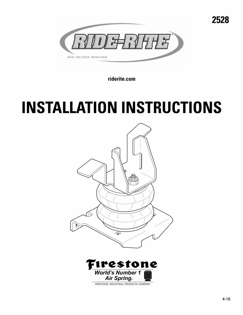
PARTSCompare the parts below to your kit. Assure you have all pieces, and organize them for an easier installation.
MAIN KIT CONTENTS
PAR
T #
6401
x 2 AIR SPRING
PAR
T #
5720
x 2 LOWER BRACKET
PAR
T #
3429
x 2 BAIL CLAMP
PA
RT
# 57
19
x 1 LEFT SIDEUPPER BRACKET
PAR
T #
5721
x 2 JOUNCE BUMPERCUP INSERT
PAR
T #
1004
x 1 HEAT SHIELD
PA
RT
# 57
18
x 1 RIGHT SIDEUPPER BRACKET
PAR
T #
5433
x 2 AXLE STRAPBRACKET
PAR
T #
9415
x 1 AIR LINE TUBE(22 FEET)
A24-760-7560 INFLATION VALVE BRACKET KIT
PAR
T #
9483
x 1NO-DRILL INFLATION VALVE BRACKET
PAR
T #
9488
x 2 LARGE NYLON TIE
A21-760-2528 HARDWARE PACK
PAR
T #
3430
x 2 3/8" - 16 x 2"FLAT HEAD BOLT
PAR
T #
3064
x 23/4" INTERNAL TOOTH LOCK WASHER
PAR
T #
3032
x 2INFLATION VALVEAND VALVE CAPASSEMBLY
PAR
T #
3142
x 2 3/8" - 16 x 5/8" FLAT HEAD BOLT
PAR
T #
3033
x 4 5/16" FLAT WASHER
PAR
T #
3015
x 2 3/8" - 16 x 7" CARRIAGE BOLT
PAR
T #
3295
x 2 3/4" - 16 HEX NUT
PAR
T #
3046
x 2 AIR FITTING
PAR
T #
0899
x 2 THERMAL SLEEVE
PAR
T #
3032
x 8 3/8" - 16FLANGE NUT
PAR
T #
9036
x 7 NYLON TIE

riderite.com3
CONTENTS AND OVERVIEWPAGE 4 INSTALL JOUNCE
BUMPER CUP
PAGE 5 UPPER & LOWER BRACKETINSTALLATION
PAGE 6 AIR SPRING ALIGNMENT & INSTALLATION
PAGE 7 FASTEN BAIL CLAMP
PAGE 8 FASTEN CARRIAGEBOLTS
PAGE 9 HEAT SHIELD &PASSENGER SIDE
PAGE 10 AIR LINE TUBE &INFLATION VALVE INSTALLATION
PAGE 11 INSTALL & ROUTE AIR LINE TUBE
PAGE 12 CHECKING THE SYSTEM
PAGE 13 FIXING ANAIR LEAK
PAGE 14 FINISHING THEINSTALLATION
AIR FITTING
JOUNCE BUMPER CUP INSERT
LEFT SIDE UPPER BRACKET
3/8"- 16 x 2"FLAT HEAD BOLT
AIR SPRING
3/8"- 16 x 7"CARRIAGE BOLT
3/8"- 16 x 7"CARRIAGE BOLT
BAIL CLAMP
3/4"- 16 HEX NUT
3/8"- 16 x 5/8"FLAT HEAD BOLT
3/8"- 16 FLANGE NUTSFasten to Bail Clamp.
3/8"- 16 FLANGE NUT
AXLE STRAP BRACKET
3/4" INTERNAL TOOTHLOCK WASHER
Vehicle front
LOWER BRACKET
3/8"- 16 FLANGE NUT
AXLE
LEAF SPRINGS
ALIGNMENT PIN*See important note - Step 5.

2528 Installation Instructions 4
JOUNCE BUMPER CUP INSERT MUST REMAIN SEATED AT ALL TIMES DURING THE INSTALLATION. IF NOT, IT CAN FALL OUT DURING OPERATION!
JOUNCE BUMPERCUP INSERT
Install and seatJounce BumperCup Insert.
Notches on JounceBumper Cup Insertface downward.
Vehicle front
Unfasten and remove existing jounce bumper from the vehicle.
NOTE: The metal bumper cupstays on the truck!
JOUNCE BUMPER CUP
EXISTING JOUNCE BUMPER
Vehicle front
REMOVE EXISTING JOUNCE BUMPER
INSTALL JOUNCE BUMPER CUP INSERT
1
2
START THE INSTALLATION ON THE LEFT SIDE OF THE VEHICLE WHEN FACING FORWARD.
VIEW FROM BOTTOM
SEATED
NOT SEATED
X
JOUNCE BUMPER CUP ON TRUCK
FLANGE
JOUNCE BUMPER CUP INSERT
JOUNCE BUMPER CUP ON TRUCK
FLANGE
JOUNCE BUMPER CUP INSERT
ROTATE

riderite.com5
Vehicle front
Fasten to Jounce Bumper Cup Insert.
3/8"- 16 x 2"FLAT HEAD BOLT
LEFT SIDEUPPER BRACKET
Taller Upper Bracketleg faces front of vehicle.
Slide Upper Bracket tight to vehicle frame.
FASTEN UPPER BRACKET TO JOUNCE BUMPER CUP INSERT
INSTALL AIR SPRING TO LOWER BRACKET
3
4
3/8"- 16 x 5/8" FLAT HEAD BOLT
AIR SPRING
LOWER BRACKET
DO NOT FULLY TIGHTEN THE BOLT AT THIS STAGE. TORQUE TO SPEC IN STEP 5.

2528 Installation Instructions 6
INSTALLING THE RIGHT SIDE? REMEMBER STEP 9 FIRST!
UPPER BRACKET
LEFT SIDEUPPER BRACKET
Must fully seatinto alignment
hole selectedabove.
ROTATE ASSEMBLY TOUSE FRONT OR BACK
ALIGNMENT HOLE
VIEW FROM BELOW
ALIGNMENT PIN
MAKE ALIGNMENTMARKS
AIR COMBO STUD
Vehicle front
AIR FITTINGThread into inside of Air Combo Stud.Tighten until threadlock coating is fully engaged.
3/4" INTERNAL TOOTH LOCK WASHER
3/4"- 16 HEX NUTThread onto outside of Air Combo Stud.
3/8"- 16 x 5/8" FLAT HEAD BOLTMatch alignment marks.
INSTALL AIR SPRING ASSEMBLY TO UPPER BRACKET 5
ALIGNMENT PIN ON AIR SPRINGS MUST BE INSTALLED TO FULLY SEAT INTO ONE OF THE ALIGNMENT HOLES IN THE UPPER BRACKET. FAILURE TO DO SO WILL CAUSE IT TO BE PUSHED INTO THE BEAD PLATE, CREATING AN AIR LEAK, AND RESULTING IN AN AIR SPRING FAILURE THAT IS NOT WARRANTABLE. THE ALIGNMENT PIN CANNOT HOLD 2,500 LBS! IT IS USED FOR ALIGNMENT ONLY!
1 Follow guidelinesbelow to dry fitassembly. Makealignment marksas shown.
2 Remove assembly and match align-ment marks you made.
3 Tighten 3/8"-16 x 5/8" Flat Head bolt to 15-20 ft lbs. 4 Install assembly
and follow theguidelines.
riderite.com7
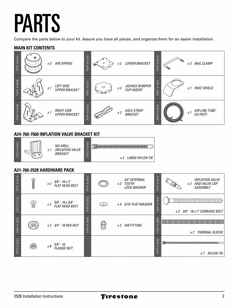
Guide Bail Clampthreaded ends underthe leaf spring stack.
NOTE: Lower Bracket cradlesexisting leaf spring stack U-bolts.
Alternate tightening to draw Lower Bracket evenly to the leaf spring stack.
BAIL CLAMP
3/8"- 16 FLANGE NUT
3/8"- 16 FLANGE NUT
AXLE
LEAF SPRINGS
Vehicle front
SECURE LOWER BRACKET BAIL CLAMP6
FROM THIS VIEW, THE AIR SPRING SHOULD BE STRAIGHT FROM SIDE TO SIDE.
LEFT SIDE VIEW FROM REAR
LOWER BRACKET
AIR SPRING
UPPER BRACKET
FRAME RAIL
BAIL CLAMP
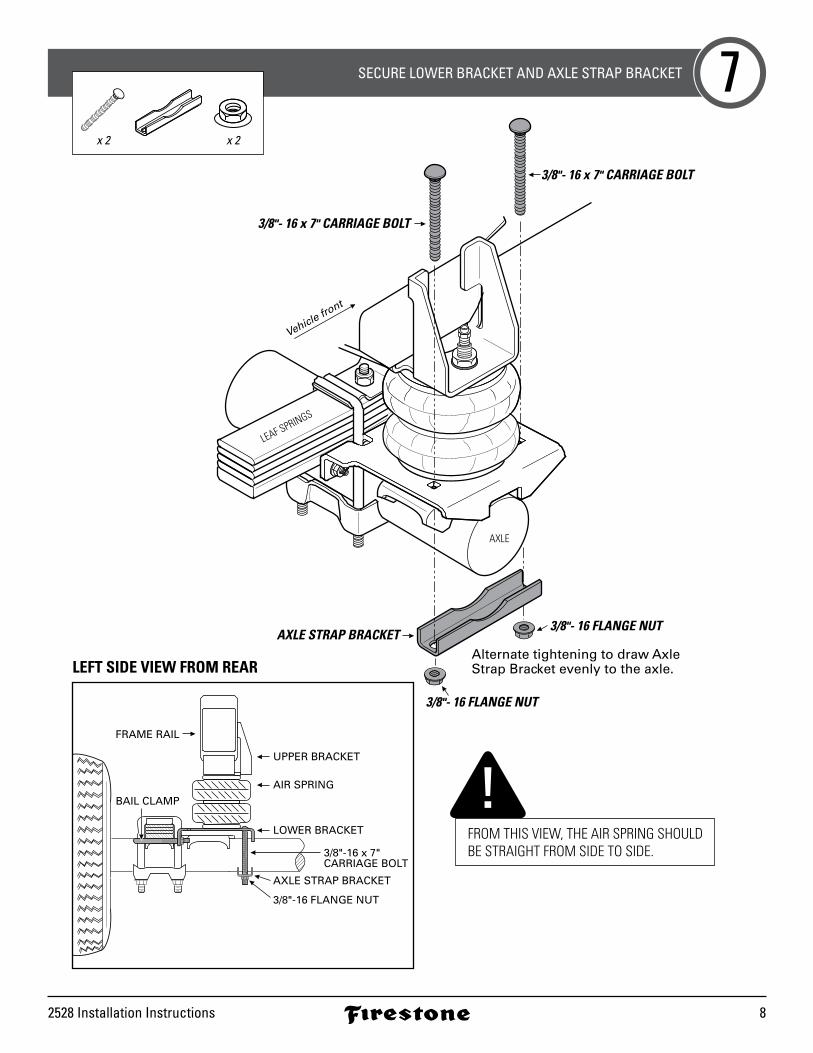
USE YOUR HAND TO CHECK FOR THE PROPER CLEARANCE AROUND THE AIR SPRING. IF YOUR HAND DOES NOT FIT BETWEEN THE AIR SPRING AND OTHER COMPONENTS, IT WILL RUB!
x 2
2528 Installation Instructions 8
3/8"- 16 x 7" CARRIAGE BOLT
3/8"- 16 FLANGE NUTAXLE STRAP BRACKET
3/8"- 16 FLANGE NUT
3/8"- 16 x 7" CARRIAGE BOLT
Vehicle front
AXLE
LEAF SPRINGS
Alternate tightening to draw Axle Strap Bracket evenly to the axle.
SECURE LOWER BRACKET AND AXLE STRAP BRACKET 7
FROM THIS VIEW, THE AIR SPRING SHOULD BE STRAIGHT FROM SIDE TO SIDE.
LEFT SIDE VIEW FROM REAR
LOWER BRACKET
3/8"-16 x 7" CARRIAGE BOLT
AXLE STRAP BRACKET
3/8"-16 FLANGE NUT
AIR SPRING
UPPER BRACKET
FRAME RAIL
BAIL CLAMP
"
x 2 x 2

riderite.com9
HEAT SHIELD
AIR SPRING
Position Heat Shield toclosest point of exhaust.
DO NOT PLACE DIRECTLYABOVE AXLE.
INSTALL RIGHT SIDE WITH HEAT SHIELD8AWESOME! You’re done with the left side. The right side installation is the same, with the addition of this step. Go complete Steps 2-4 for the right side, then complete this step before continuing to Step 5.
RIGHT SIDE INSTALLATION MUST INCLUDE HEAT SHIELD!

2528 Installation Instructions 10
1 Secure the Air Inflation Valve Bracket to a pro-tected, secure location. PROCEED TO STEP 3.
2 Select a protected location to install the Inflation Valves, such as the bumper or the body of the vehicle.
Drill two 5/16" holes for Inflation Valve install locations.
3 Install Inflation Valve assembly as shown.
INSTALL INFLATION VALVES
CUT THE AIR LINE TUBE INTO TWO EQUAL LENGTHS
9
10
x 2 x 2x 4 x 2
1 Match Air Line Tube ends.
2 Find center of Air Line Tube, make a square cut with tube cutter or sharp utility knife.
LARGENYLON TIES
Inflation Valveinstall locations.
BUMPER
INFLATIONVALVES
EXAMPLEINFLATION VALVE
AIR LINE TUBE
VALVE CAP
INFLATION VALVE NUT
5/16” - 16 FLAT WASHER
Vehicle body,bumper orInflation ValveBracket.
DO Make sure the cut is as square as possible.Use a tube cutter or sharp utility knife. DON’T Fold or kink the Air Line Tube.
Cut the Air Line Tube at an angle.Use pliers, scissors, snips,saws, or side cutters.
Square cut
90˚AIR LINE TUBE AIR LINE TUBE AIR LINE TUBE AIR LINE TUBE
PROPER AND IMPROPER CUTS IN THE AIR LINE TUBE
AIR LINE TUBE
IF USING THE OPTIONAL NO-DRILL INFLATION VALVE BRACKET, CHOOSE OPTION 1. IF DRILLING, CHOOSE OPTION 2. INFLATION VALVES MUST BE ACCESSIBLE BY AN AIR CHUCK.
5/16”
riderite.com11
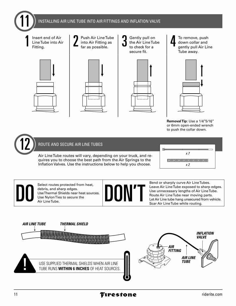
INSTALLING AIR LINE TUBE INTO AIR FITTINGS AND INFLATION VALVE
ROUTE AND SECURE AIR LINE TUBES
11
12
1 Insert end of Air Line Tube into Air Fitting. 2 Push Air Line Tube
into Air Fitting asfar as possible. 3 Gently pull on
the Air Line Tube to check for a secure fit.
4 To remove, pushdown collar andgently pull Air LineTube away.
DOSelect routes protected from heat,debris, and sharp edges.Use Thermal Shields near heat sources.Use Nylon Ties to secure the Air Line Tube. DON’T
Bend or sharply curve Air Line Tubes.Leave Air Line Tube exposed to sharp edges.Use unnecessary lengths of Air Line Tube.Route Air Line Tube near moving parts.Let Air Line tube hang unsecured from vehicle.Scar Air Line Tube while routing.
Air Line Tube routes will vary, depending on your truck, and re-quires you to choose the best path from the Air Springs to the Inflation Valves. Use the instructions below to help you choose.
AIR LINE TUBE THERMAL SHIELD
INFLATION VALVE
AIR LINE TUBE
AIRFITTING
x 7
x 2
USE SUPPLIED THERMAL SHIELDS WHEN AIR LINE TUBE RUNS WITHIN 6 INCHES OF HEAT SOURCES.
Removal Tip: Use a 1/4”, 5/16”, or 6mm open-ended wrench to push the collar down.

2528 Installation Instructions 12
1 Place an air chuck onto theInflation Valve and fill thesystem to 70 PSI.
70PSI
2 Spray fittings with soap and water mixture.
WATER+
SOAP
3 Observe bubbles.
SMALL SOAP BUBBLESTHAT DO NOT EXPAND
SOAP BUBBLESTHAT EXPAND
CHECKING THE AIR SYSTEM 13
AIR SPRINGS INFLATE QUICKLY. CHECK AIR PRESSURE WHILE INFLATING.
NO LEAKS?Congratulations! Continue to Step 15 to finish installation. Review the Operating Instructions.
LEAK?Bummer. Continue to Step 14 to fix the leak.

riderite.com13
FIXING AN AIR LEAK141 Press the air valve on end
of Inflation Valve to release all air pressure.
0PSI
AIR VALVE
STILL HAVE A LEAK?Refer to the Troubleshooting section of the Instruction Manual. If the leak persists, or if there is an issue with a leaking part, call 1-800-888-0650; Option 1; Option 1 for Tech Support.
LEAK AT AIR LINE TUBE AND AIR FITTING
LEAK AT BASE OF AIR FITTING ON AIR SPRING
LEAK OUT OF THE VALVE CORE ON INFLATION VALVE
Release Air Line Tube (see page 11). Review proper cuts and procedures in Step 10. Repeat Steps 11 and 13.
Tighten Air Fitting one turn or until leak stops.
Tighten valve corewith valve core wrenchon Inflation Valve Cap.
EXHAUST ALL AIR FROM THE SYSTEM PRIOR TO RELEASING AIR LINE TUBES FROM AIR FITTINGS.
2528 Installation Instructions 14
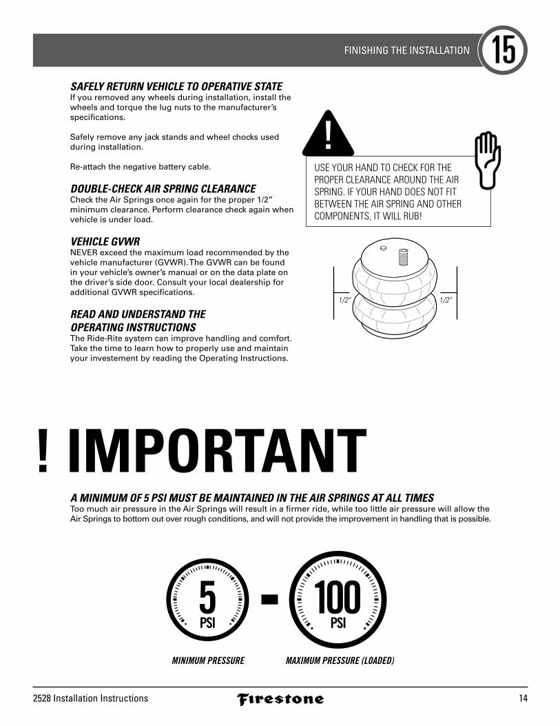
FINISHING THE INSTALLATION 15SAFELY RETURN VEHICLE TO OPERATIVE STATEIf you removed any wheels during installation, install the wheels and torque the lug nuts to the manufacturer’s specifications.
Safely remove any jack stands and wheel chocks used during installation.
Re-attach the negative battery cable.
DOUBLE-CHECK AIR SPRING CLEARANCECheck the Air Springs once again for the proper 1/2” minimum clearance. Perform clearance check again when vehicle is under load.
VEHICLE GVWRNEVER exceed the maximum load recommended by the vehicle manufacturer (GVWR). The GVWR can be found in your vehicle’s owner’s manual or on the data plate on the driver’s side door. Consult your local dealership for additional GVWR specifications.
READ AND UNDERSTAND THE OPERATING INSTRUCTIONSThe Ride-Rite system can improve handling and comfort. Take the time to learn how to properly use and maintain your investement by reading the Operating Instructions.
! IMPORTANTA MINIMUM OF 5 PSI MUST BE MAINTAINED IN THE AIR SPRINGS AT ALL TIMESToo much air pressure in the Air Springs will result in a firmer ride, while too little air pressure will allow the Air Springs to bottom out over rough conditions, and will not provide the improvement in handling that is possible.
1/2"1/2"
USE YOUR HAND TO CHECK FOR THE PROPER CLEARANCE AROUND THE AIR SPRING. IF YOUR HAND DOES NOT FIT BETWEEN THE AIR SPRING AND OTHER COMPONENTS, IT WILL RUB!

NEED INSTALLATION HELP? 1-800-888-0650Select Option 1 for Ride-Rite; Select Option 1 for Technical Support.
Or, email us at [email protected]. If emailing, please include photos to help us better diagnose and understand any problems you may be experiencing.
riderite.com
2528
1-16
BEFORE YOU DRIVE, CONFIRM THE FOLLOWING: Do you have a minimum of 5PSI in your Air Springs?
Are your Air Springs standing 5 1/2" - 6 1/2" tall?
Are your Air Springs properly aligned, left-to-right and front-to-back?
Are your nuts and bolts tight?
Put your paper work back into the sleeve and keep it in your glove compartment for future reference.
You’ve been bagged…and now your suspension is Airide equipped! Show it off with the supplied decal!
5 1/2” - 6 1/2”
CONNECT WITH US @rideriteair @rideriteair Firestone RideRite Firestone Ride-Rite