installation instructions Precedent - Brad's Golf Cars,...
4
will fit Club Car ® Precedent ® 02-001/02-002 1 2 Remove factory bumper by removing the two factory bolts located in the frame. *Retain hardware euro clear/frosted lens light kit installation instructions included: tools needed: Frosted/Euro Clear 2 Tail Lights 1 Wiring Harness 8 Screws Straps Rocker Switch Phillips Head Screw Driver Cutting Tool Sandpaper Power Drill 15/32 Drill Bit Euro Clear Lens Frosted Lens Fuse Assembly Fuse Assembly Harness Harness Place Madjax light kit bumper on the frame as shown. Light Kit bracket should be placed over the top and under the bottom of frame and flush to front fascia. Attach light using hardware retained from step one. Revised December 2014
Transcript of installation instructions Precedent - Brad's Golf Cars,...

will fit Club Car® Precedent®
02-001/02-002
12
Remove factory bumper by removing the two factory bolts located in the frame. *Retain hardware
euro clear/frosted lens light kit
installation instructions
included: tools needed:Frosted/Euro Clear2 Tail Lights1 Wiring Harness8 ScrewsStrapsRocker Switch
Phillips Head Screw DriverCutting Tool SandpaperPower Drill15/32 Drill Bit
Euro Clear Lens Frosted Lens
Fuse Assembly Fuse Assembly
Harness Harness
Place Madjax light kit bumper on the frame as shown. Light Kit bracket should be placed over the top and under the bottom of frame and flush to front fascia. Attach light using hardware retained from step one.
Revised December 2014

34
65
Remove the 3 console screws as shown and retain hardware.
Attach light kit harness to factory harness as shown. For Club Car Precedent 2008+ and up, you will need to install your MJLKBH1000 before proceeding. Follow MJLKBH1000 instructions for installation. *Do not reattach your dashboard*
Locate the indentation to the right of the key switch on the instrument panel and drill a 15/32” hole for the rocker switch. Push switch into drilled hole and tighten with mounting nut.
9-Pin connector for optional Ultimate Upgrade
Route 6-pin Connector
12-pin Male Connector from Harness
12-pin Female Connector from Factory Harness
Earth - Ground (black)Load - 12v(+) constant (yellow)Supply - 12v(+) switched (yellow)
Using a multimeter to determine which yellow wire shows a constant 12v(+). The wire that does not is the switched 12v(+).
Attach harness to rocker switch as shown. And then re- attach dashboardusing hardware retained from Step 3.

78
910
Route the 6 pin headlight connector through the cutout in the passenger dash.Plug the 6 pin male wire harness connector into the 6 pin female headlight wire harness connector and wire tie harness to frame sup-port (the two extra wires on this harness are for use with the optional horn kit).
Before removing double sided tape and installing the LED Tail Lights, test fit them in their position on the rear location of the vehicle. Mark the center of the tailight hole using drawing Using a 1-1/2 inch hole saw, drill a hole in the location as shown in drawing 1 . Sand to remove sharp edges.
Position the tail lights as shown in the picture. The flat ends of the tail lights should be where the sharper curve of the body from the bag well begins a more gradual curve. If there is a gap between the tail light and the body, reposition until there is no gap.Thoroughly clean the surface area where tail lights will be mounted. *Important: Surface must be free of any dirt, wax, or products that will inhibit double sided tape from adhering properly.
Using a wire snake, pull the tail light connector through the hole in the rear body.Connect the tail lights to the vehicle tail light wiring harness.Determine the desired location of the tail lights.Remove the double sided tape from the back of the tail light and mount to the rear body.
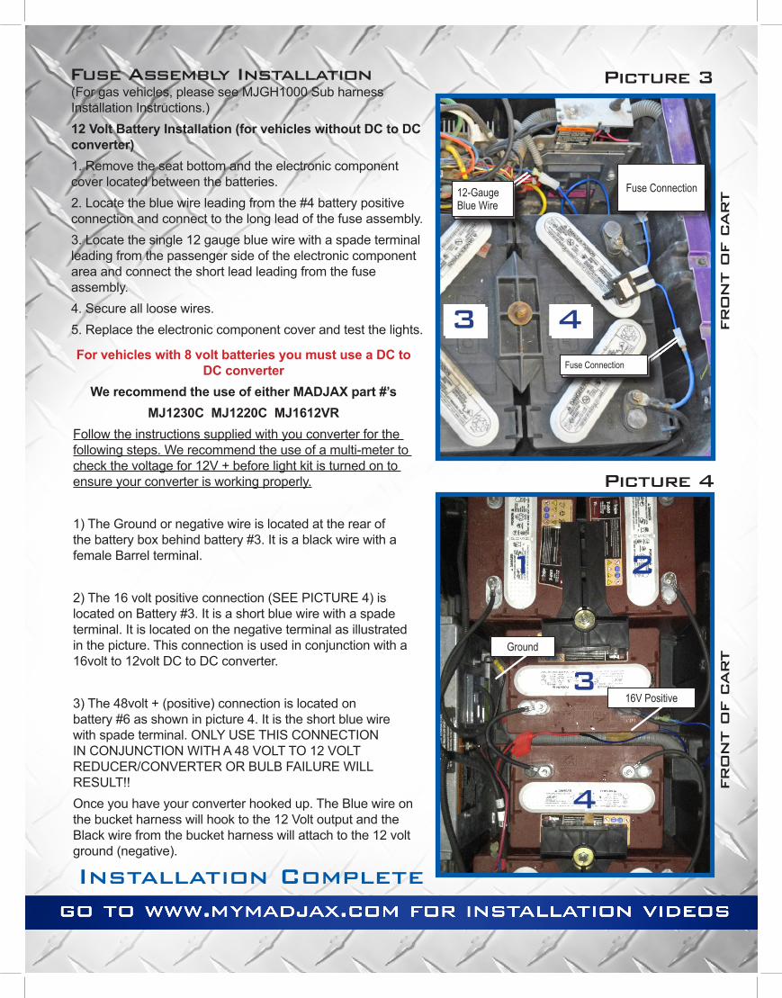
(For gas vehicles, please see MJGH1000 Sub harness Installation Instructions.)12 Volt Battery Installation (for vehicles without DC to DC converter)1. Remove the seat bottom and the electronic component cover located between the batteries.2. Locate the blue wire leading from the #4 battery positive connection and connect to the long lead of the fuse assembly.3. Locate the single 12 gauge blue wire with a spade terminal leading from the passenger side of the electronic component area and connect the short lead leading from the fuse assembly.4. Secure all loose wires.5. Replace the electronic component cover and test the lights.
For vehicles with 8 volt batteries you must use a DC to DC converter
We recommend the use of either MADJAX part #’sMJ1230C MJ1220C MJ1612VR
Follow the instructions supplied with you converter for the following steps. We recommend the use of a multi-meter to check the voltage for 12V + before light kit is turned on to ensure your converter is working properly.
1) The Ground or negative wire is located at the rear of the battery box behind battery #3. It is a black wire with a female Barrel terminal.
2) The 16 volt positive connection (SEE PICTURE 4) is located on Battery #3. It is a short blue wire with a spade terminal. It is located on the negative terminal as illustrated in the picture. This connection is used in conjunction with a 16volt to 12volt DC to DC converter.
3) The 48volt + (positive) connection is located on battery #6 as shown in picture 4. It is the short blue wire with spade terminal. ONLY USE THIS CONNECTION IN CONJUNCTION WITH A 48 VOLT TO 12 VOLT REDUCER/CONVERTER OR BULB FAILURE WILL RESULT!!Once you have your converter hooked up. The Blue wire on the bucket harness will hook to the 12 Volt output and the Black wire from the bucket harness will attach to the 12 volt ground (negative).
Picture 4
Fuse Connection
Fuse Connection
12-Gauge Blue Wire
16V Positive
Ground
Installation Complete