Installation Instructions - lci1.com · PDF fileInstallation Instructions ... adequate space...
12
Table of Content Page Introduction 1 Pre-Install Planning 1 Application Guide 2 Control Panel Install 4 Mounting Assemblies: Motor/Pump/Manifold 5 Cylinder 6 Hydraulic Lines 7 Wire Connections 8 Bleeding Hydraulic Lines 9 System Check 10 Appendix A: Bracket Template 11 Insert Information 11 Limited Warranty 12 Installation Instructions Installation Instructions Products Company, Inc. 230 Davidson Avenue Cottage Grove, Oregon 97424 (541) 942-3888 www.kwikee.com © 2003 Kwikee Products Co., Inc. Kwikee Doc #1422191 Rev. Mar. 2004 Hydraulic Leveling Systems #2000, #2010, #3000, and #30130 Introduction The Level Best 2000, 2010, 3000, 3010 leveling and stabilizing systems are electronically controlled, hyraulically operated units that consist of a 12-volt DC powered motor/pump/manifold assembly with fluid reservoir, hydraulic hoses, four hydraulically operated jacks, and a motor control unit and switch panel. The systems are designed to meet the varying requirements of class ‘A’ to class ‘C’ motorhomes. The configuration of chassis and vehicular components can vary greatly from one manu- facturer to another. The installation procedures outlined in this instruction sheet repre- sent a generalized approach. Your installation application may vary. If, after reading this manual, you have questions regarding the installation of the Level Best system, please contact our Customer Service Department at 1-800-736-9961. Getting your questions answered in advance will help to ensure a smooth installation and proper operation. Pre-Installation Planning Prior to beginning the actual installation, examine the vehicle and visualize the mounting position of each of the systems main components: Motor/pump/manifold assembly Four hydraulic cylinders (for LB2000 and LB2010, 2 left hand/driver side, 2 right hand/passenger side) Control panel Keep the lengths of hoses and wiring, as well as the physical dimensions of each piece in mind and plan accordingly. Locate the component pieces within the range of the hose lengths. Allow adequate clearance around each component to connect wiring and hoses and provide easy access for performing routine maintenance. See Figure 1 on Page 3 for general physical references. NOTE: If your vehicle does not readily lend itself to the suggested system configuration and alternatives do not appear feasible, feel free to contact the Kwikee Customer Service Department for assistance at 1-800-736-9961.
Transcript of Installation Instructions - lci1.com · PDF fileInstallation Instructions ... adequate space...

Table of ContentPage
Introduction 1Pre-Install Planning 1Application Guide 2Control Panel Install 4Mounting Assemblies:
Motor/Pump/Manifold 5Cylinder 6
Hydraulic Lines 7Wire Connections 8Bleeding Hydraulic Lines 9System Check 10Appendix A:
Bracket Template 11Insert Information 11
Limited Warranty 12
InstallationInstructions
Installation Instructions
Products Company, Inc.
230 Davidson AvenueCottage Grove, Oregon 97424(541) 942-3888www.kwikee.com
© 2003 Kwikee Products Co., Inc.Kwikee Doc #1422191 Rev. Mar. 2004
Hydraulic Leveling Systems #2000, #2010, #3000, and #30130
IntroductionThe Level Best 2000, 2010, 3000, 3010 leveling and stabilizing systems are electronically controlled, hyraulically operated units that consist of a 12-volt DC poweredmotor/pump/manifold assembly with fluid reservoir, hydraulic hoses, four hydraulicallyoperated jacks, and a motor control unit and switch panel. The systems are designed tomeet the varying requirements of class ‘A’ to class ‘C’ motorhomes.
The configuration of chassis and vehicular components can vary greatly from one manu-facturer to another. The installation procedures outlined in this instruction sheet repre-sent a generalized approach. Your installation application may vary. If, after reading thismanual, you have questions regarding the installation of the Level Best system, pleasecontact our Customer Service Department at 1-800-736-9961. Getting your questionsanswered in advance will help to ensure a smooth installation and proper operation.
Pre-Installation PlanningPrior to beginning the actual installation, examine the vehicle and visualize the mountingposition of each of the systems main components:
Motor/pump/manifold assembly
Four hydraulic cylinders (for LB2000 and LB2010, 2 left hand/driver side, 2 right hand/passenger side)
Control panel
Keep the lengths of hoses and wiring, as well as the physical dimensions of each piecein mind and plan accordingly. Locate the component pieces within the range of the hoselengths. Allow adequate clearance around each component to connect wiring and hosesand provide easy access for performing routine maintenance. See Figure 1 on Page 3for general physical references.
NOTE: If your vehicle does not readily lend itself to the suggested systemconfiguration and alternatives do not appear feasible, feel free to contactthe Kwikee Customer Service Department for assistance at 1-800-736-9961.

MOTOR / PUMP / MANIFOLD ASSEMBLY LOCATION
An ideal location for mounting the motor/pump/maniford assembly is immediately forward andbelow the engine radiator. Be sure not to restrict ventilation to the radiator coolingsurfaces. This position should provide easy access to the vehicle battery and offer anaccessible area for attaching the hydraulic hoses, making wiring connections andperforming routine maintenance. Close proximity to the chassis battery is preferred.
JACK LOCATION
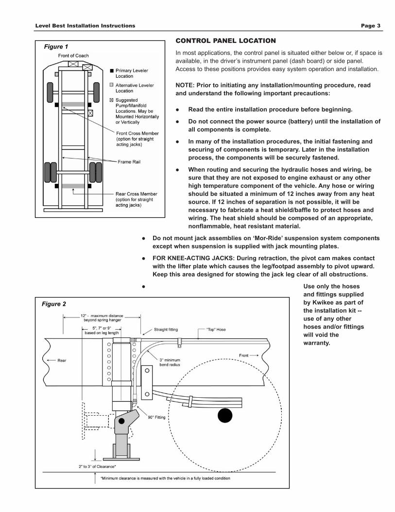
Examine the under carriage of the vehicle. You will notice that the constructionof the chassis super structure includes two parallel frame rails extending almostthe entire length of the vehicle. The ideal location for the rear hydraulic cylinders(or rear jacks) is along the exterior side of the frame rail and behind the rearaxle, as close as possible and no more than 12” behind the rear spring hanger.
The ideal location for the front jacks is along the exterior side of the frame rail,behind the front axle.
For Knee-acting Jacks: The pivot direction is toward the rear of thevehicle. Be certain the the jacks have adequate space to swing up and allowadequate space for the leg and footpad in the stowed position. (See Figure 1on Page 3.)
For Straight-acting Jacks: For lighter-duty chassis, Kwikee recommends that jacksbe positioned as close to the chassis cross member as possible (see Figure 1 on Page3.) If no cross member is near the selected jack location, a cross member can beattached between the frame rails to help strengthen the chassis. (Kwikee can supplycross members for this purpose.)
NOTE: On a gasoline-powered chassis do not mount the rear jacks morethan 12” behind the rear spring hanger.
Motor / Pump / Maniford Assembly
Level Best Installation Instructions Page 2
Level Best Installation Instructions Page 3
CONTROL PANEL LOCATION
In most applications, the control panel is situated either below or, if space isavailable, in the driver’s instrument panel (dash board) or side panel.Access to these positions provides easy system operation and installation.
NOTE: Prior to initiating any installation/mounting procedure, readand understand the following important precautions:
Read the entire installation procedure before beginning.
Do not connect the power source (battery) until the installation of all components is complete.
In many of the installation procedures, the initial fastening andsecuring of components is temporary. Later in the installationprocess, the components will be securely fastened.
When routing and securing the hydraulic hoses and wiring, besure that they are not exposed to engine exhaust or any otherhigh temperature component of the vehicle. Any hose or wiringshould be situated a minimum of 12 inches away from any heatsource. If 12 inches of separation is not possible, it will benecessary to fabricate a heat shield/baffle to protect hoses andwiring. The heat shield should be composed of an appropriate,nonflammable, heat resistant material.
Do not mount jack assemblies on ‘Mor-Ride’ suspension system componentsexcept when suspension is supplied with jack mounting plates.
FOR KNEE-ACTING JACKS: During retraction, the pivot cam makes contactwith the lifter plate which causes the leg/footpad assembly to pivot upward.Keep this area designed for stowing the jack leg clear of all obstructions.
Use only the hosesand fittings suppliedby Kwikee as part ofthe installation kit --use of any otherhoses and/or fittingswill void thewarranty.
Figure 2
Figure 1

Level Best Installation Instructions Page 4
Inspect the location for flush mounting the control panel and ensure that there is adequatespace for the box portion of the control panel and the multi-wire cable connections. Using thetemplate in Appendix A, layout and cut the opening. Route multi-wire cable through theopening in the dash and insert the connectors into the receptacles on the back of the controlpanel. The control panel should fit snugly into this opening. Remember, it is easier to cut theopening too small and enlarge it to fit than it is to cut it too large and have to fill the openingback in.
Flush Panel Mounting Application (not shown)
One method of installing the control panel uses the mounting bracket to install it below thedriver’s instrument panel. If there is enough space, flush mounting the control panel into thevehicle instrument panel is another option.
First determine where the wires are to be routed. Look for any pre-existing holes that can beused to route the control panel wiring from the pump manifold to the control panel location. Ifno hole can be found, drill a 1 1/2” hole through the fire wall near the selected installationsite. Route the wire through the hole to the control panel location.
Control Panel Installation
NOTE: When the controlpanel has been installed andthe wires have been routed,seal any holes you may havedrilled from the interior to theexterior of the vehicle with asilicone sealant.
Bracket mounting

The motor/pump/manifold assembly requires an area 26” long x 12” x 12” deep forinstallation. See Figure 3.
The bottom of the pump has been tapped for mounting with two 3/8”-16 x 1 bolds. Theassembly can be mounted horizontally or vertically. See Figure 4.
On a work bench, install the 45O hydraulic fittings into the manifold prior to mounting.Determine which direction the hoses will be routed and point the fittings in theappropriate directions.
For some applications the pump assembly can be mounted to an existing chassis crossmember in front of, below, or beside the radiator. The location of the pump assemblyshould not block or restrict the flow of air to the radiator. Be sure there is sufficientclearance around the assembly to connect the hoses and wiring, as well as room forchecking and filling the reservior.
Once a position satisifying these conditions has been determined, align and drill two1/2” diameter mounting holes, centered 3 1/4” apart. Position the pump/motor assemblyover the mounting holes and secure it in place using the two 3/8”-16 x 1 bolts and lockwashers. Attach the ground cable using the 5/16” bolt in the side of the motor mountingblock. See Figure 5.
Next, route the other end of the black ground cable to the chassis battery and connect itto the negative (-) battery post. Connect the 8-foot long #4 red battery cable to the studon the pump motor solenoid and route it to the chassis battery of the RV. The end of thecable with the fusible link should end at the battery. See Figures 5 and 6.
NOTE: Do not connect red battery cable to the battery post at this time.
Mounting the Motor / Pump / Manifold Assembly
Level Best Installation Instructions Page 5
NOTE: Hydraulic lines will berouted to the top of themanifold. Be sure there isadequate working spaceabove the manifold formaking the hose connections.
NOTE: To prevent debris fromentering the hydraulic systemand damaging valve seals, thehose ends have been sealedwith removable soft plasticplugs. Do not remove theseplugs until you are ready toattach the hydraulic lines.
Figure 3
Figure 4
Figure 5
Figure 6: DO NOT connect the red battery cable to the positive battery post at this time.

With all four mounting positions prepared on the chassis frame, the next step is topartially assemble the hydraulic cylinder components.
On a work bench, install the 90o hydraulic fitting into the opening closest to the bottom ofthe cylinder. See Figure 7. Insert the nontapered end with the self-sealing ‘O’ ring intothe cylinder. With the nipple pointing up, tighten the fitting in a range of 50-150 in./lb.Install the straight hydraulic fitting in the upper threaded opening and tighten to amaximum of 150 in./lb.
Return to the undercarriage with the cylinder assemblies. Place the cylinders onto themounting brackets. On knee-acting jacks locate the assembly so that the legs pivot tothe rear of the coach. Install and tighten the top two mounting bolts just enought to holdthe cylinders in place.
From the uppermost position onthe mounting bracket, hydrauliccylinders can be adjusteddownward a maximum of 3” andmaintain an adequate mount. Thiscylinder mounting adjustmentrange allows for fine tuning thesystem. When the cylinder is in itsfinal mounting position, secure themounting bolts to 80 ft/lb. Nowinstall the middle and lower sets ofbolts and tighten to 80 ft./lb.
Install the jack leg position sensorwiring. The jack leg positionsensors are to be wired in series.Attach the yellow 16 gauge wire toTD1/jack reed switch wire locatedat the pump manifold harness. Useheat shrink butt connectors whenmaking all of these connections.Run the yellow wire to the first jackleg sensor and attach the wire toone of the two sensor wires. Attachanother yellow wire to theremaining wire at the sensor andrun this wire to the next jack legand sensor. Continue this processuntil all four sensors are connected. At the last sensor, attach the yellow wire to theremaining sensor wire. Run the other end of the yellow wire to the grounding bolt on thepump and connect with a 5/16” ring terminal. See Figure 8 on Page 7.
Level Best Installation Instructions Page 6
Each cylinder assembly includes a mounting flange, hydraulic cylinder, leg assembly,and lifter plate (knee-acting jacks only.)
Knee-acting Jacks: Position the cylinder assembly to allow adequate space for themotion of the jack leg (5”, 7”, or 9” from the center of the cylinder depending on thelength of the leg being used.)
For all Level Best systems: When using the mounting bracket, the top of the bracketshould be flush with the top of the chassis. Placing the bracket flush with the top of thechassis will allow for maximum ground clearance. With these conditions satisfied, clampand weld the mounting bracket in place.
Mounting Cylinder Assembly with Weld-on BracketsCAUTION: Whenwelding to thechassis rail use care
to avoid damaging any of thechassis equipment. Thisequipment includes wiring,fuel, brake, hydraulic and/orcompressed air lines. Alwayscheck the opposite side of thewelding surface for anythingthat could be damaged by theheat from the weld.
The standard bracket kit(Kwikee part #9069480) willwork with Chevrolet, Freight-liner, Spartan, Ford and light-duty Ford chassis.On newer Freightliner chassis,use of the factory Freightlinerbracket is recommended.On the Oshkosh and the F53Ford chassis with the V-10engine, it will be necessary touse a set of mounting brackets(Kwikee part #906950000.)These brackets are requiredwhen the levelers are mountedover the leaf springs. Thesebrackets space the levelers outfrom the frame rail so thatduring the extension of knee-acting jacks, the footpads willnot contact the leaf springswhen they swing down.See Appendix A for additionalmounting options.
CAUTION: Prior towelding on the
chassis frame, anymicroprocessor controlledelectronics such as enginemonitoring devices andKwikee electric entry stepsshould be disconnected --both power feed and groundconnections.
Failure to disconnect any ofthese components can causedamage to the devices andvoid the warranty.
Figure 7: Use adequate hose lengths andobserve recommended radius bends (3”minimum) to avoid kinks, flattened hose,and restricted flow capabilities.

The leveling system comes with eight factoryhydraulic lines. Each hose is labeled on one endto correspond to a port on the manifold. SeeFigure 10.
NOTE: To prevent debris from entering thehydraulic system and damaging the valveseals, the hose ends have been sealed withremovable plastic plugs. Do not remove theseplugs until you are ready to attach thehydraulic lines.
Starting at the right rear cylinder, attach the RR4Bhose end to the bottom fitting on the cyliner andtighten to 50-150 in./lbs.
Attach the hose end labeled RR4T to the upperfitting on the cylinder and tighten to 50-150 in./lb.See Figure 7. Using the remaining hoses, repeatthis procedure for the other cylinders.
Continue by routing and loosely securing thehydraulic lines and yellow reed switch wires alongthe vehicle undercarriage to the pump/manifold.As you route these lines forward to thepump/manifold. Use wire ties to loosely securethem to the frame rail. Use a sufficient number ofstraps so that when the lines are finally secured,they will not sag or sway when the vehicle is inmotion. Do not strap the hydraulic lines to anymoving or heat-producing parts of the vehicle.
All fittings should be connected to the manifoldand tightened to 50-150 in./lb. Connect the swivelfitting of each hydraulic line to its correspondingvalve port fitting as labeled on the manifold.Tighten to 50-150 in./lb. See Figure 10.
Level Best Installation Instructions Page 7
Figure 8
Figure 9
Attaching Hydraulic Lines
INSTALLER NOTE: For Level Best kits sold in the aftermarket, hose labels will be supplied loose in the hose kit box.Labels should be applied to the hoses as they are routed during installation.
LABEL VALUE PORT
LF1T 1TLF1B 1BRF2T 2TRF2B 2BLR3T 3TLR3B 3BRR4T 4TRR4B 4B
Figure 10

With the wiring from the Control Panel routed to the pump manifold, complete the wireconnections. Refer to Figure 11 for wire connection information.
1. Check that all system ground harness connections are firmly attached.
2. Use a heat shrink butt connector to attach theyellow wire from the leg position reed switches to thewhite wire labeled ‘TDI/Jack Reed Switch’ on thepump manifold wiring harness. See Figure 12.
Attach the ground wire from the reed switches to theground bolt on the pump. See Figure 6.
3. Locate the vehicle fuse box and attach the yellowignition sense wire (IGN) to an ignition activatedcircuit (circuit to be fused at a maximum of 7.5amps.)
NOTE: The positive battery cable should still bedisconnected at this point.
4. Level Best systems are equipped with a park brake interlock. The interlock isdesigned to allow operation of the system only when the vehicle parking brake is set.
In the chassis wiring harness, identify the park brake signal wire. The park brake switchand signal wire will usually be found on, or near the park brake pedal assembly. Thiswire will show ground or 12-volts positive when the park brake is applied. The type ofsignal will vary from one type chassis to another. Once you have located the appropriatewire, determine the type of signal by using a volt-ohm meter while engaging the parkbrake. If a positive signal is present the use of a relay is required. See Figure 11 Inset.
Next, splice the blue park brake wire (PKBK) from the control unit into the signal wire.
5. The ‘Run Only’ wire (Figure 11) at the control is used for special applications andshould be ignored.
6. The final connection is the 8 ft. red #4 cable from the pump motor solenoid to thepositive (+) terminal of the chassis battery.
Level Best Installation Instructions Page 8
Completing the Wiring Connections
Figure 12
Figure 11
NOTE: Most new class ‘A’motor home chassis areequipped with anautomatically applied parkbrake system. Thesesystems automatically applythe parking brake when thetransmission is shifted into‘park.’
In the chassis wiring harnessyou will need to identify thepark brake signal wire. Thiswire will carry a positive (+)12-volt or ground signal. Asignal wire can generally befound in one of the followingplaces:
Steering column justbelow the head and rim atthe upper adjustmentpoint or at the base just above the floor line.
Front bulkhead wiringconnector - located on the driver side of the vehicleand accessible eitherunder the dash or underthe hood.
At the slave cylinderactuator of the park brake.
Possibly in the trans-mission wiring harness.
Once you have located theappropriate wire, determinethe type of signal by using avolt-ohm meter whileengaging the park brake. If apossitve signal is present,the use of a relay is required.See Figure 11 Inset. Splice apigtail into this wire asexplained in instructions.

Level Best Installation Instructions Page 9
Prior to initiating the bleeding process, verify that all the fittings on the cylinders and themanifold have been tightened to 50-150 in./lb. Also check that all the swaged hosecouplers are tightened to the fittings at 50-150 in./lb. The entire system must be filledwith hydraulic fluid during the bleeding process. It is recommended that the reservoir befilled with 1 1/4 gallons of fluid to start the process. The hoses and cylinders holdapproximately 2-2.5 gallons of fluid, therefore it will be necessary to refill the reservoirseveral times during the bleeding process.
With the reservoir filled and the fittings checked, turn the system on by starting thecoach and pressing the power button on the control panel. Begin extending one of therear cylinders. Initially, the system contains mostly air, which prevents the manifoldvalves from sealing and causes all cylinders to extend erratically. As the hydraulic fluidbegins to fill the lines and cylinders, the manifold valves will seal and each cylinder willbegin to act independently.
When the reservoir begins to run low on fluid, the resistance of the fluid within thepump lessens and the sound of the pump increases in pitch. Retract the legscompletely and replenish the fluid in the reservoir.
Continue to extend the cylinder until it reaches the end of its stroke, then retract allcylinders. With air in the lines, the cylinders will emit squeaking and humming noisesand move in a jumpy manner. As air is purged from the system, the cylinders will movein a smoother, quieter manner. It may be necessary to extend and retract each cylinderseveral times to completely purge the lines of air.
When the system has been bled, retract all levelers and check the fluid level in thereservoir. With all cylinders fully retracted, the fluid level in the reservoir should be justvisible in the filler fitting.
Manually Bleeding the CylindersMost cylinders will bleed themselves. However, if you have difficulty with a particularcylinder during the bleeding process, it is possible to manually bleed a cylinder. Extendthe cylinder until it touches the ground.
CAUTION: Do not lift the coach.
Loosen the top hose fitting on the cylinder. You will hear air escaping. Do not removethe fitting from the cylinder to vent this air. Tighten the fitting again when air ceases tovent and only fluid is escaping. Operate the cylinder in and out several times to checkfor smooth operation. Repeat manual bleeding process as necessary.
Hydraulic System and Electrical ConnectionsBe sure that:
All hydraulic fittings on the cylinders and manifold assembly have been tightened to50-150 in./lb.All hydraulic hose connections have been tightended to the fittings at 50-150 in./lb.All cylinder mouting bolts have been tightend to 80 ft./lb.All electrical power delivery and ground connections are securely fastened.There are no leaks.
NOTE: Be sure that any holes from interior to exterior of vehicle made during theinstallation process have been completely sealed with a silicone sealant.
Bleeding the Hydraulic System
CAUTION: Do notrun the pumpwithout fluid as
damage to the pump mayoccur. Do not engage thepump motor for periodsgreater than 30 seconds asmotor damage may occur.
WARNING: Duringthe retracting of the
jacks, the cam on the upperportion of the leg will makecontact with lift plate andcause the leg assembly toswing upward; failure to stayclear of the levelers when thesystem is being operated canresult in severe injury.
NOTE: When filling andbleeding the system, usetransmission fluid only.Kwikee recommends usingDextron III. Do not mix fluids.When checking the fluid levelin the reservoir, all levelersmust be in the retracted (ALL UP) postion.

NOTE: The park brake must be set and the ignition on for the Level Best Systemto operate.
Once all the system components have been installed a system check is recommendedto verify all Level Best functions are operational.
Operating Level Best is accomplished by using the buttons on the control panel. SeeFigure 13. The buttons are organized to represent the actual positions of the jacks onthe coach.
1. Using the four individual ‘UP’ / ‘DN’ (down) buttons, verify that each jack can beextended and retracted separately and that the associated yellow LED indicator lightsduring operation.
2. The ‘Bi-Level’ buttons, marked with triangles and arranged in a diamond pattern,operate pairs of jacks simultaneously. Press each of the buttons and verify that theappropriate pair of jacks can be extended together and that the associated pair of LEDindicators light during operation.
3. After placing all jacks in the extended position, press the ‘All Up’ button and verifythat all four jacks retract together into the travel postion and that all four yellow LEDindicators light during operation. The LED light under the ‘All Up’ should turn green andthe pump will shut off automatically 2-5 seconds after all the jacks are fully retracted.
Level Best Installation Instructions Page 10
WARNINGS: Do not use theLevel Best systems as a liftfor changing tires or workingunder the vehicle.
Never check for hydraulicfluid leaks using your handsand/or any other body part.the leaking fluid is underpressure and is capable ofcutting and penetrating yourskin, resulting in severeinjury.
When extending the rearstabilizers, do not lift thewheels beyond groundcontact. This overrides thebraking effect of both thetransmission park and theparking brake and makes itpossible for the vehicle toroll unexpectedly forward orbackward off the jacks. Thiscould cause severe injury oreven death.
Holding a control panelbutton switch in the ‘UP’ or‘DN’ position for a timeperiod longer than necessaryto fully extend or retract thehydraulic cyliners, can causeoverheating and damage tothe pump motor as well asthe electrical components.
Do not use the levelers as anemergency brake. They arenot designed for any type ofvehicle breaking purpose.
Do not use the levelers onicy or slick surfaces onwhich the footpads may slip.
Figure 13
NOTE: If system is equipped with automatic leveling,see “Level Best Operation Guide” for informationabout ‘AUTO MODE’ operations.
Testing the System
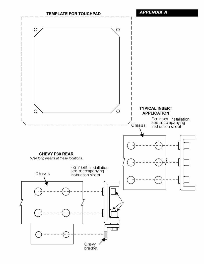
APPENDIX A

Products Company, Inc.
230 Davidson AvenueCottage Grove, Oregon 97424(541) 942-3888www.kwikee.com © 2004 Kwikee Products Co., Inc. Kwikee Doc #1422191 Rev. Mar. 2004
Level Best Installation Instructions Page 12
NOTE: Any parts returned for warranty service/repair with wires cut will result invoiding of the warranty.
NOTE: It is important to read and understand this manual thoroughly beforeinitiating any installation of the jacks. Kwikee Products Company, Inc., assumes noliability for damages or injury resulting from the improper installation or operation ofthe Level Best® Hydraulic Leveling/Stabilizing System.
Kwikee Products Company, Inc. (“Kwikee”) warrants to the original purchaser that the Level Best®hydraulic leveling/stabilizing system is free from defects in material and workmanship for a period of5 years from the date of purchase. Kwikee’s obligation under this warranty is limited to the repair orreplacement of defective parts returned to Kwikee's' factory.
Kwikee will pay for the labor required to repair or replace its products on claims submitted within 2years of the date of purchase. The warranty on repaired or replaced parts shall be limited to theunexpired duration of the original warranty.
This warranty does not apply to products or parts that, in Kwikee’s opinion, have been subject toabuse, accident, alteration, improper installation/repair, inadequate maintenance or deterioration due tonormal wear. This warranty does not apply to electrical wiring or hydraulic hoses. The purchaser shallpay all shipping or other transportation charges for any warranty claim.
Kwikee makes no warranty (and disclaims any implied warranty) regarding the merchantability, fitnessfor a particular purpose or the suitability of this product for use with other products. In no event shallKwikee be liable for incidental, consequential or property damage arising from the purchase and/or useof this product or any claim hereunder. This warranty is in lieu of all other express and impliedwarranties. Kwikee neither assumes nor authorizes any other person to assume any liability forwarranty claims not provided herein.
This warranty gives you specific legal rights including other rights that may vary from state to state.Some states do not allow limitations on implied warranties and exclusion or limitation of incidental orconsequential damages, therefore the limitations and exclusions contained herein may not apply to you.
Any questions regarding warranty claims should be directed to your dealer or contact Kwikee ProductsCompany. Address correspondence to: Kwikee Customer Service Representative, 230 Davidson Ave.,Cottage Grove, Oregon 97424; or contact us by telephone at 1-800-736-9961.
Limited Warranty