Installation Instructions - Jeep Parts & Accessories for ... · Installation Instructions Eibach...
18
D3261 www.eibach.com Page 1 Kit Contents Description Part Number Qty Front Spring 2894.603 2 Rear Spring 2894.604 2 Front Damper 2894.8009 2 Rear Damper 2894.8010 2 Front Hardware Kit 2897.980HKF 1 -End Links 8000977.0 2 -Bump Stop Spacer, Front 8000911 2 -Screw, Cap, 6mm-1.0 x 16mm L. H14024848 2 -Screw, Self Tapping, 5/16-18 x ¾: L. H21021612 2 -Cable Tie, Nylon H70065500 8 Rear Hardware Kit 2897.980HKR 1 -End Links 8000977.0 2 -Bump Stop Spacer, Rear 8000959 2 -Screw, Cap, 6mm-1.0 x 16mm L. H14024848 2 -Bolt, Allen, 8mm-1.25 x 75mm L. H31085057 4 -Nut, Nylock, 8mm-1.25 H63023700 4 -Cable Tie, Nylon H70065500 2 Track Bar, Front 5.10007K 1 Brake Line Kit SP4864-001 1 Alignment Bolts 5.82390K 1 Track Bar Kit 8000942HK 1 -Track Bar Bracket 8000942 1 -Nut, Stover H65072000 1 -Washer, ½” H50076500 2 -Screw, Hex ½”-20 x 2.75” H13072324 1 -Screw, Hex 3/8”-24 x 1.25” H13071918 1 -Washer, 3/8” H50076300 2 -Nut, 3/8”-24 H65071900 1 NOTES: Read All Instructions Before Beginning Installation Installation of a Eibach Pro Lift System set should only be performed by a qualified mechanic experienced in the installation and removal of suspension componentry. Use of a hoist is highly recommended and will substantially reduce installation time. Never work on or under a vehicle unless it is properly supported by safety stands and wheels are blocked. Never use impact wrenches or guns to install or remove shock absorber piston components, shafts and piston rod nuts. Never disassemble or cut open shock absorbers and/or shock absorber inserts. They contain oil and gas under high pressure. After installation, it is always important to inspect and adjust the following if necessary: - Wheel alignment such as camber, caster & toe. - Tire and/or wheel fender clearance. - Brake line clearance and attachments. - Brake anti-locking and anti-skid system sensors. Installation Instructions Eibach Pro Lift System - #2894.980 2007-14 Jeep Wrangler, 2 dr., 3.8L V6, Incl. Sahara & Rubicon Note: This kit requires the use of an aftermarket exhaust crossover for front driveshaft clearance. Eibach Springs, Inc. 264 Mariah Circle Corona, California 92879-1751 USA Tech Support 800-222-8811 Ext 114
Transcript of Installation Instructions - Jeep Parts & Accessories for ... · Installation Instructions Eibach...
D3261 www.eibach.com Page 1
Kit Contents Description Part Number Qty
Front Spring 2894.603 2 Rear Spring 2894.604 2 Front Damper 2894.8009 2 Rear Damper 2894.8010 2 Front Hardware Kit 2897.980HKF 1 -End Links 8000977.0 2 -Bump Stop Spacer, Front 8000911 2 -Screw, Cap, 6mm-1.0 x 16mm L. H14024848 2 -Screw, Self Tapping, 5/16-18 x ¾: L. H21021612 2 -Cable Tie, Nylon H70065500 8 Rear Hardware Kit 2897.980HKR 1 -End Links 8000977.0 2 -Bump Stop Spacer, Rear 8000959 2 -Screw, Cap, 6mm-1.0 x 16mm L. H14024848 2 -Bolt, Allen, 8mm-1.25 x 75mm L. H31085057 4 -Nut, Nylock, 8mm-1.25 H63023700 4 -Cable Tie, Nylon H70065500 2 Track Bar, Front 5.10007K 1 Brake Line Kit SP4864-001 1 Alignment Bolts 5.82390K 1 Track Bar Kit 8000942HK 1 -Track Bar Bracket 8000942 1 -Nut, Stover H65072000 1 -Washer, ½” H50076500 2 -Screw, Hex ½”-20 x 2.75” H13072324 1 -Screw, Hex 3/8”-24 x 1.25” H13071918 1 -Washer, 3/8” H50076300 2 -Nut, 3/8”-24 H65071900 1
NOTES: Read All Instructions Before Beginning Installation Installation of a Eibach Pro Lift System set should only be performed by a qualified mechanic experienced
in the installation and removal of suspension componentry. Use of a hoist is highly recommended and will substantially reduce installation time. Never work on or under a vehicle unless it is properly supported by safety stands and wheels are blocked. Never use impact wrenches or guns to install or remove shock absorber piston components, shafts and
piston rod nuts. Never disassemble or cut open shock absorbers and/or shock absorber inserts. They contain oil and gas
under high pressure. After installation, it is always important to inspect and adjust the following if necessary:
- Wheel alignment such as camber, caster & toe. - Tire and/or wheel fender clearance. - Brake line clearance and attachments. - Brake anti-locking and anti-skid system sensors.
Installation Instructions
Eibach Pro Lift System - #2894.980 2007-14 Jeep Wrangler, 2 dr., 3.8L V6, Incl. Sahara & Rubicon Note: This kit requires the use of an aftermarket exhaust crossover for front driveshaft clearance.
Eibach Springs, Inc. 264 Mariah Circle Corona, California 92879-1751 USA Tech Support 800-222-8811 Ext 114
D3261 www.eibach.com Page 2
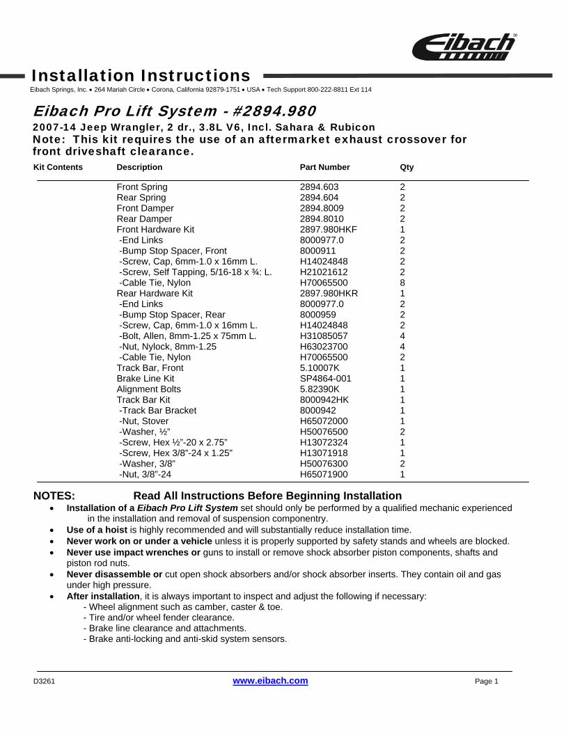
Tightening torque for piston rod nut Thread Size Nm ft-lb Thread Size Nm ft-lb Thread Size Nm ft-lb M8 25 18 M12 x 1.25 35 26 M14 x 1.50 50 37 M10 x 1.0 20 15 M12 x 1.50 40 29 M14 x 2.00 50 37 M10 x 1.25 20 15 M12 x 1.75 40 29 M16 x 1.50 50 37 M10 x 1.50 20 15
D3261 www.eibach.com Page 3
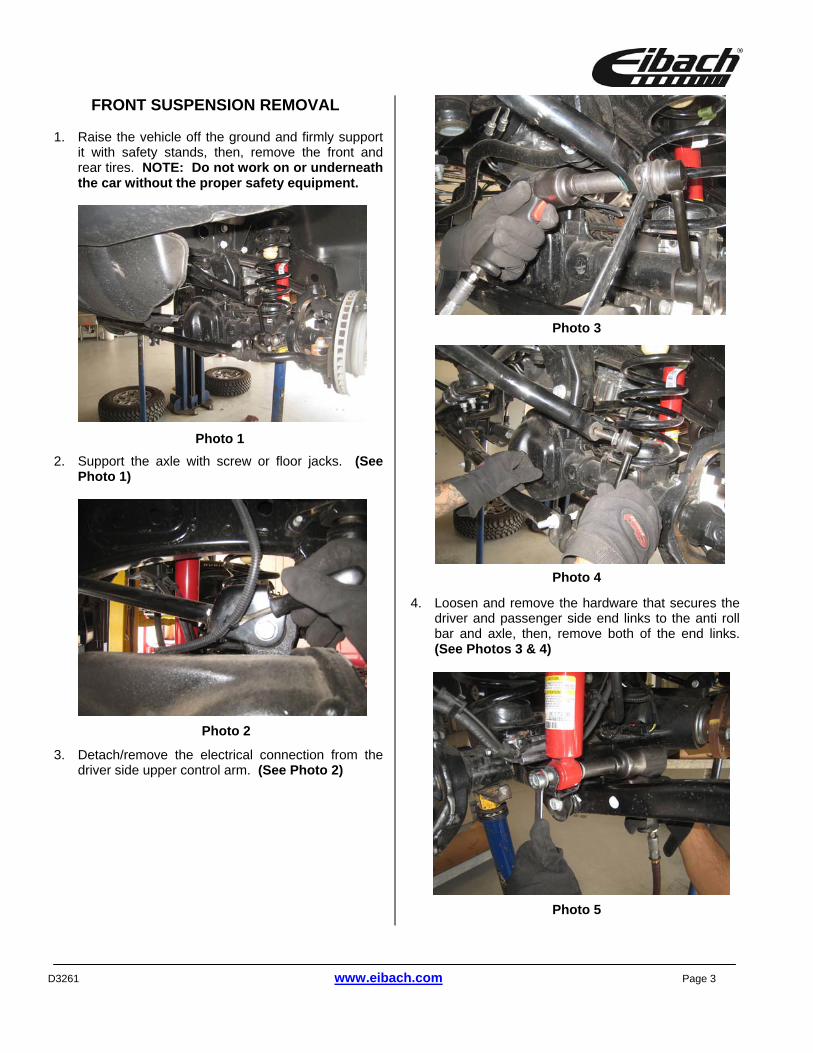
FRONT SUSPENSION REMOVAL
1. Raise the vehicle off the ground and firmly support it with safety stands, then, remove the front and rear tires. NOTE: Do not work on or underneath the car without the proper safety equipment.
2. Support the axle with screw or floor jacks. (See Photo 1)
3. Detach/remove the electrical connection from the driver side upper control arm. (See Photo 2)
4. Loosen and remove the hardware that secures the driver and passenger side end links to the anti roll bar and axle, then, remove both of the end links. (See Photos 3 & 4)
Photo 1
Photo 2
Photo 3
Photo 4
Photo 5
D3261 www.eibach.com Page 4
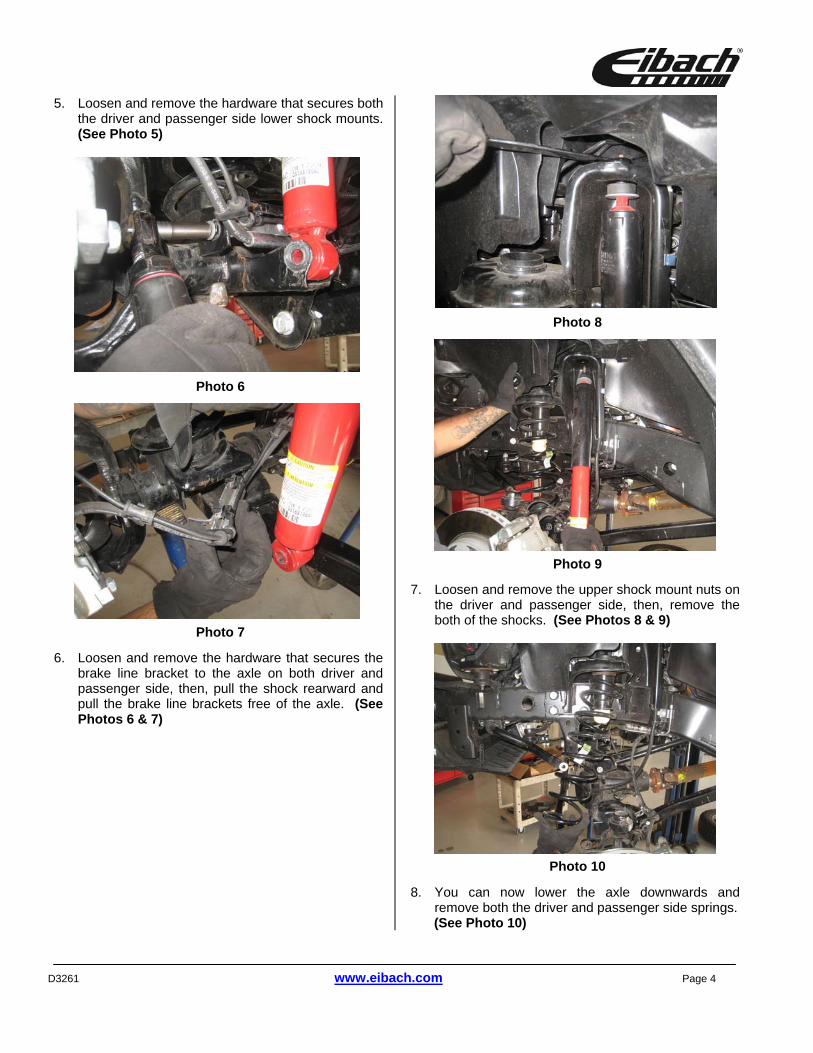
5. Loosen and remove the hardware that secures both the driver and passenger side lower shock mounts. (See Photo 5)
6. Loosen and remove the hardware that secures the
brake line bracket to the axle on both driver and passenger side, then, pull the shock rearward and pull the brake line brackets free of the axle. (See Photos 6 & 7)
7. Loosen and remove the upper shock mount nuts on
the driver and passenger side, then, remove the both of the shocks. (See Photos 8 & 9)
8. You can now lower the axle downwards and
remove both the driver and passenger side springs. (See Photo 10)
Photo 8
Photo 6
Photo 7
Photo 9
Photo 10
D3261 www.eibach.com Page 5
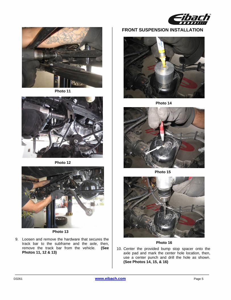
9. Loosen and remove the hardware that secures the
track bar to the subframe and the axle, then, remove the track bar from the vehicle. (See Photos 11, 12 & 13)
FRONT SUSPENSION INSTALLATION
10. Center the provided bump stop spacer onto the axle pad and mark the center hole location, then, use a center punch and drill the hole as shown. (See Photos 14, 15, & 16)
Photo 12
Photo 13
Photo 16
Photo 15
Photo 14
Photo 11
D3261 www.eibach.com Page 6
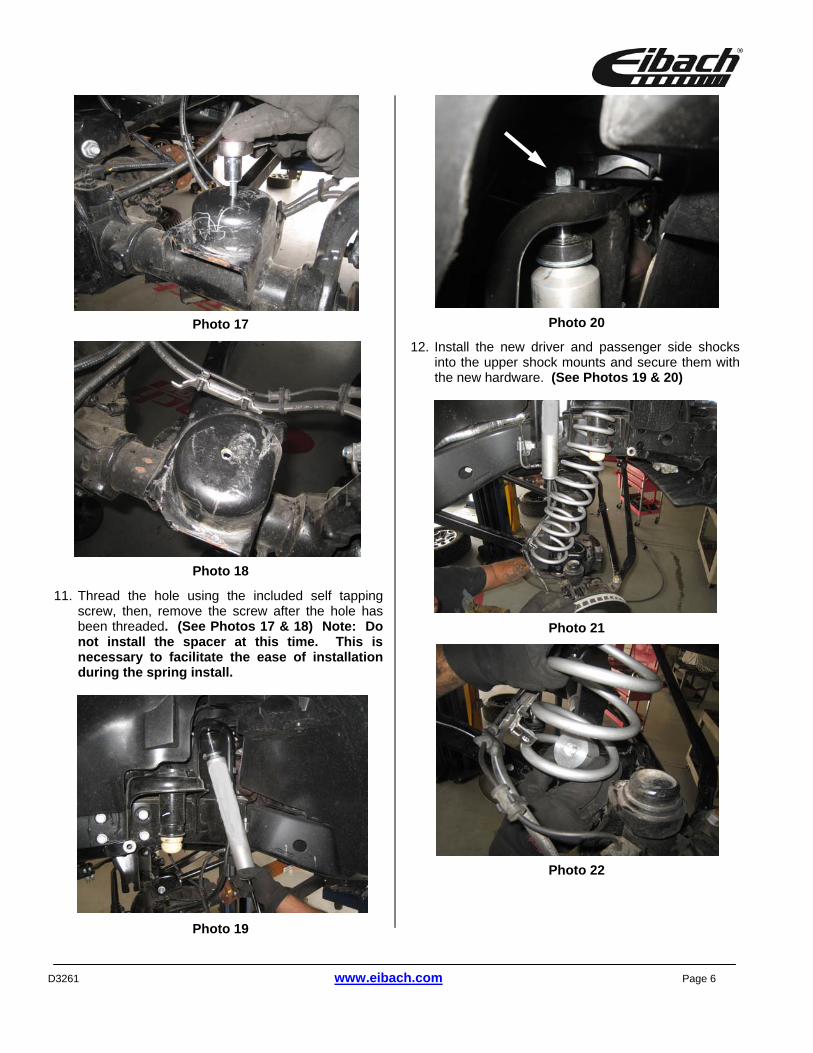
11. Thread the hole using the included self tapping screw, then, remove the screw after the hole has been threaded. (See Photos 17 & 18) Note: Do not install the spacer at this time. This is necessary to facilitate the ease of installation during the spring install.
12. Install the new driver and passenger side shocks into the upper shock mounts and secure them with the new hardware. (See Photos 19 & 20)
Photo 19
Photo 18
Photo 17 Photo 20
Photo 21
Photo 22
D3261 www.eibach.com Page 7
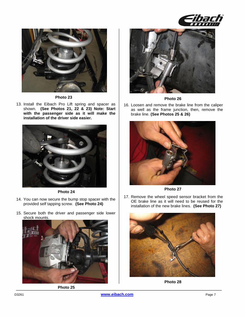
13. Install the Eibach Pro Lift spring and spacer as
shown. (See Photos 21, 22 & 23) Note: Start with the passenger side as it will make the installation of the driver side easier.
14. You can now secure the bump stop spacer with the
provided self tapping screw. (See Photo 24)
15. Secure both the driver and passenger side lower shock mounts.
16. Loosen and remove the brake line from the caliper
as well as the frame junction, then, remove the brake line. (See Photos 25 & 26)
17. Remove the wheel speed sensor bracket from the
OE brake line as it will need to be reused for the installation of the new brake lines. (See Photo 27)
Photo 23
Photo 25
Photo 27
Photo 26
Photo 24
Photo 28
D3261 www.eibach.com Page 8
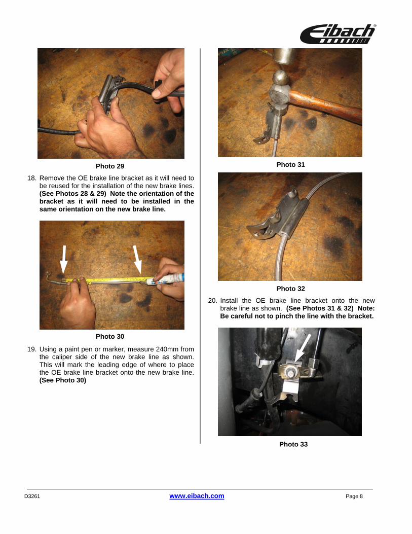
18. Remove the OE brake line bracket as it will need to
be reused for the installation of the new brake lines. (See Photos 28 & 29) Note the orientation of the bracket as it will need to be installed in the same orientation on the new brake line.
19. Using a paint pen or marker, measure 240mm from the caliper side of the new brake line as shown. This will mark the leading edge of where to place the OE brake line bracket onto the new brake line. (See Photo 30)
20. Install the OE brake line bracket onto the new
brake line as shown. (See Photos 31 & 32) Note: Be careful not to pinch the line with the bracket.
Photo 29
Photo 30
Photo 31
Photo 32
Photo 33
D3261 www.eibach.com Page 9
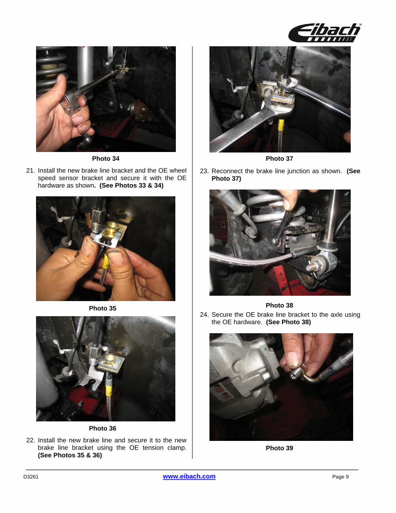
21. Install the new brake line bracket and the OE wheel
speed sensor bracket and secure it with the OE hardware as shown. (See Photos 33 & 34)
22. Install the new brake line and secure it to the new
brake line bracket using the OE tension clamp. (See Photos 35 & 36)
23. Reconnect the brake line junction as shown. (See
Photo 37)
24. Secure the OE brake line bracket to the axle using
the OE hardware. (See Photo 38)
Photo 34
Photo 36
Photo 35 Photo 38
Photo 39
Photo 37
D3261 www.eibach.com Page 10
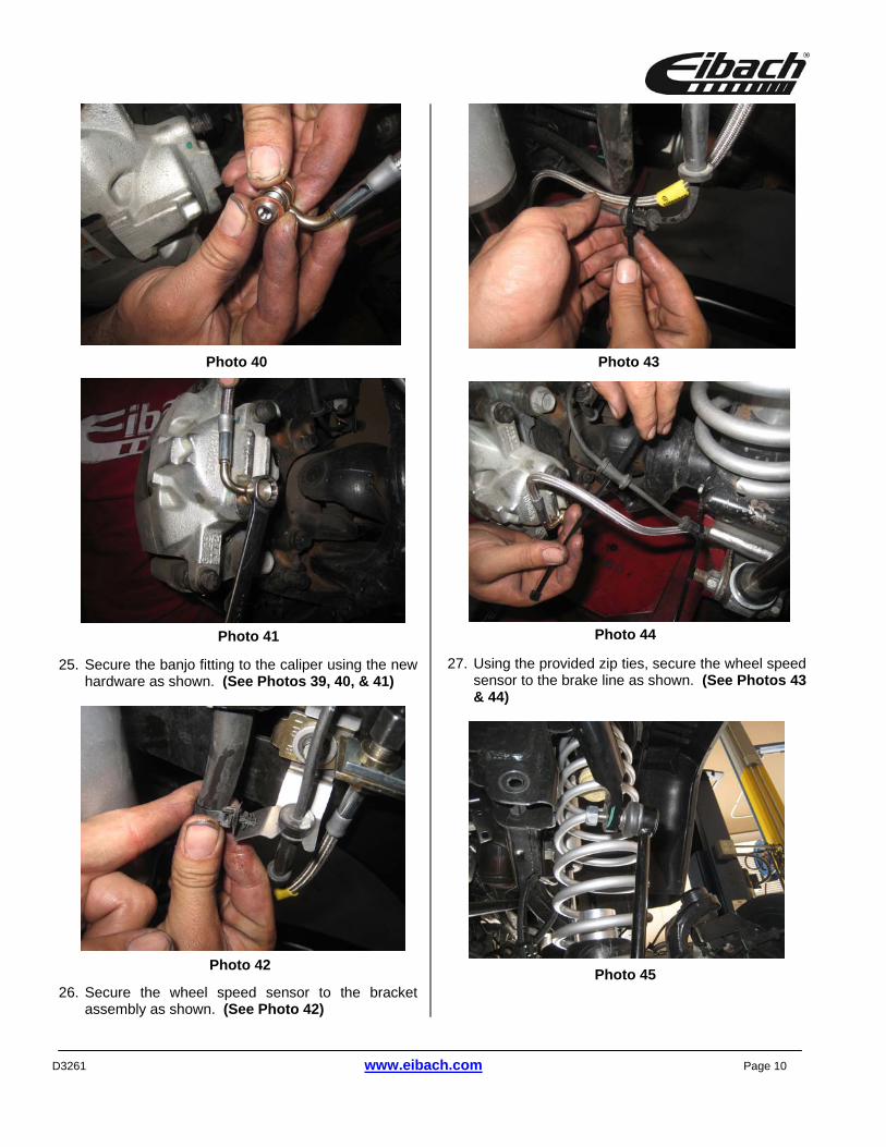
25. Secure the banjo fitting to the caliper using the new
hardware as shown. (See Photos 39, 40, & 41)
26. Secure the wheel speed sensor to the bracket
assembly as shown. (See Photo 42)
27. Using the provided zip ties, secure the wheel speed
sensor to the brake line as shown. (See Photos 43 & 44)
Photo 45
Photo 40
Photo 41
Photo 43
Photo 42
Photo 44
D3261 www.eibach.com Page 11
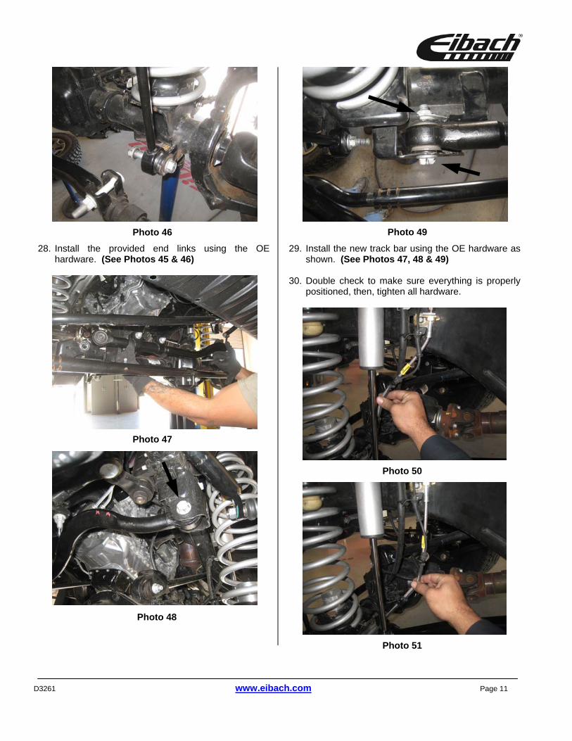
28. Install the provided end links using the OE
hardware. (See Photos 45 & 46)
29. Install the new track bar using the OE hardware as
shown. (See Photos 47, 48 & 49)
30. Double check to make sure everything is properly positioned, then, tighten all hardware.
Photo 46
Photo 48
Photo 47
Photo 49
Photo 51
Photo 50
D3261 www.eibach.com Page 12
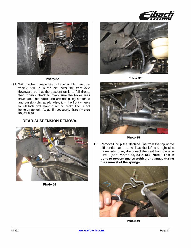
31. With the front suspension fully assembled, and the
vehicle still up in the air, lower the front axle downward so that the suspension is at full droop, then, double check to make sure the brake lines have adequate slack and are not being stretched and possibly damaged. Also, turn the front wheels to full lock and make sure the brake line is not being stretched. Adjust if necessary. (See Photos 50, 51 & 52)
REAR SUSPENSION REMOVAL
1. Remove/Unclip the electrical line from the top of the differential case, as well as the left and right side frame rails, then, disconnect the vent from the axle tube. (See Photos 53, 54 & 55) Note: This is done to prevent any stretching or damage during the removal of the springs.
Photo 53
Photo 54
Photo 55
Photo 52
Photo 56
D3261 www.eibach.com Page 13
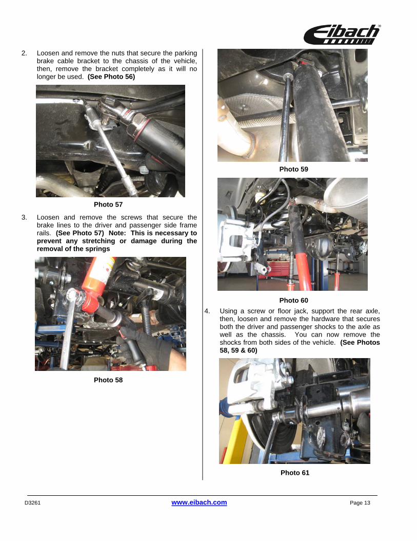
2. Loosen and remove the nuts that secure the parking brake cable bracket to the chassis of the vehicle, then, remove the bracket completely as it will no longer be used. (See Photo 56)
3. Loosen and remove the screws that secure the brake lines to the driver and passenger side frame rails. (See Photo 57) Note: This is necessary to prevent any stretching or damage during the removal of the springs
4. Using a screw or floor jack, support the rear axle, then, loosen and remove the hardware that secures both the driver and passenger shocks to the axle as well as the chassis. You can now remove the shocks from both sides of the vehicle. (See Photos 58, 59 & 60)
Photo 61
Photo 58
Photo 59
Photo 60
Photo 57
D3261 www.eibach.com Page 14
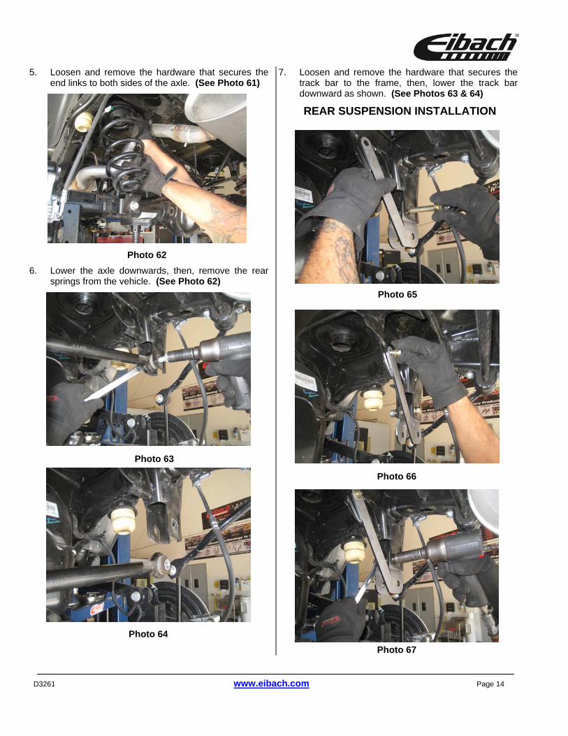
5. Loosen and remove the hardware that secures the end links to both sides of the axle. (See Photo 61)
6. Lower the axle downwards, then, remove the rear springs from the vehicle. (See Photo 62)
7. Loosen and remove the hardware that secures the track bar to the frame, then, lower the track bar downward as shown. (See Photos 63 & 64)
REAR SUSPENSION INSTALLATION
Photo 62
Photo 66
Photo 65
Photo 67
Photo 63
Photo 64
D3261 www.eibach.com Page 15
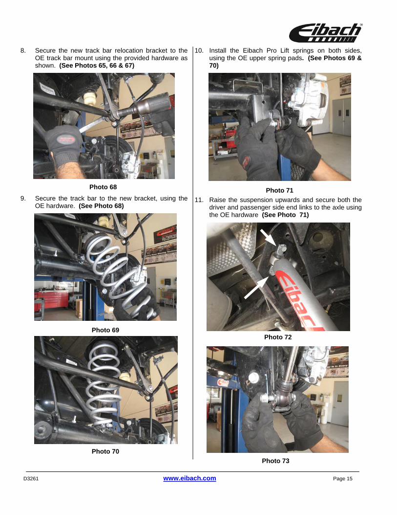
8. Secure the new track bar relocation bracket to the OE track bar mount using the provided hardware as shown. (See Photos 65, 66 & 67)
9. Secure the track bar to the new bracket, using the OE hardware. (See Photo 68)
10. Install the Eibach Pro Lift springs on both sides, using the OE upper spring pads. (See Photos 69 & 70)
11. Raise the suspension upwards and secure both the driver and passenger side end links to the axle using the OE hardware (See Photo 71)
Photo 71
Photo 69
Photo 68
Photo 73
Photo 72
Photo 70
D3261 www.eibach.com Page 16
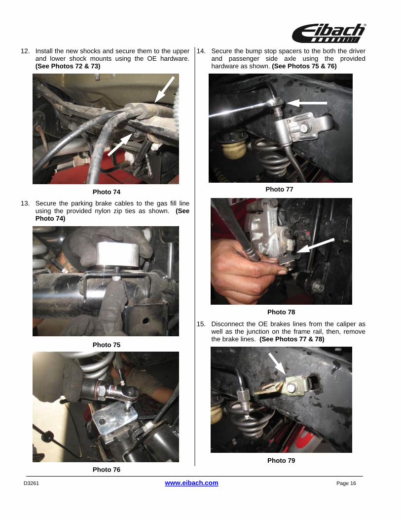
12. Install the new shocks and secure them to the upper and lower shock mounts using the OE hardware. (See Photos 72 & 73)
13. Secure the parking brake cables to the gas fill line using the provided nylon zip ties as shown. (See Photo 74)
14. Secure the bump stop spacers to the both the driver and passenger side axle using the provided hardware as shown. (See Photos 75 & 76)
15. Disconnect the OE brakes lines from the caliper as well as the junction on the frame rail, then, remove the brake lines. (See Photos 77 & 78)
Photo 76
Photo 75
Photo 77
Photo 78
Photo 79
Photo 74
D3261 www.eibach.com Page 17
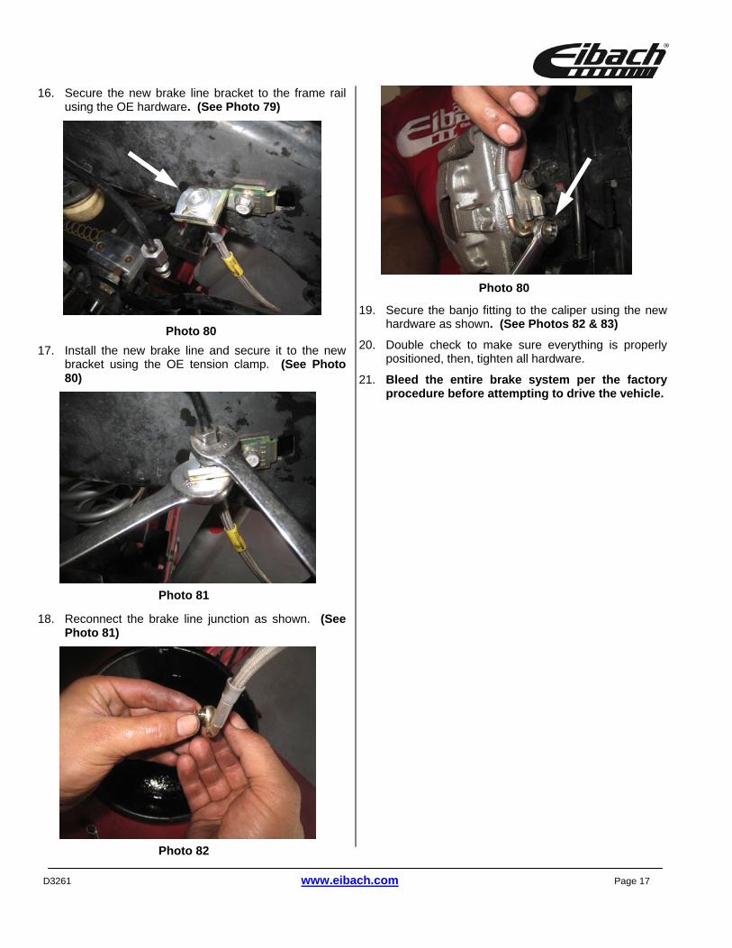
16. Secure the new brake line bracket to the frame rail using the OE hardware. (See Photo 79)
17. Install the new brake line and secure it to the new bracket using the OE tension clamp. (See Photo 80)
18. Reconnect the brake line junction as shown. (See Photo 81)
19. Secure the banjo fitting to the caliper using the new hardware as shown. (See Photos 82 & 83)
20. Double check to make sure everything is properly positioned, then, tighten all hardware.
21. Bleed the entire brake system per the factory procedure before attempting to drive the vehicle.
Photo 80
Photo 81
Photo 82
Photo 80
D3261 www.eibach.com Page 18
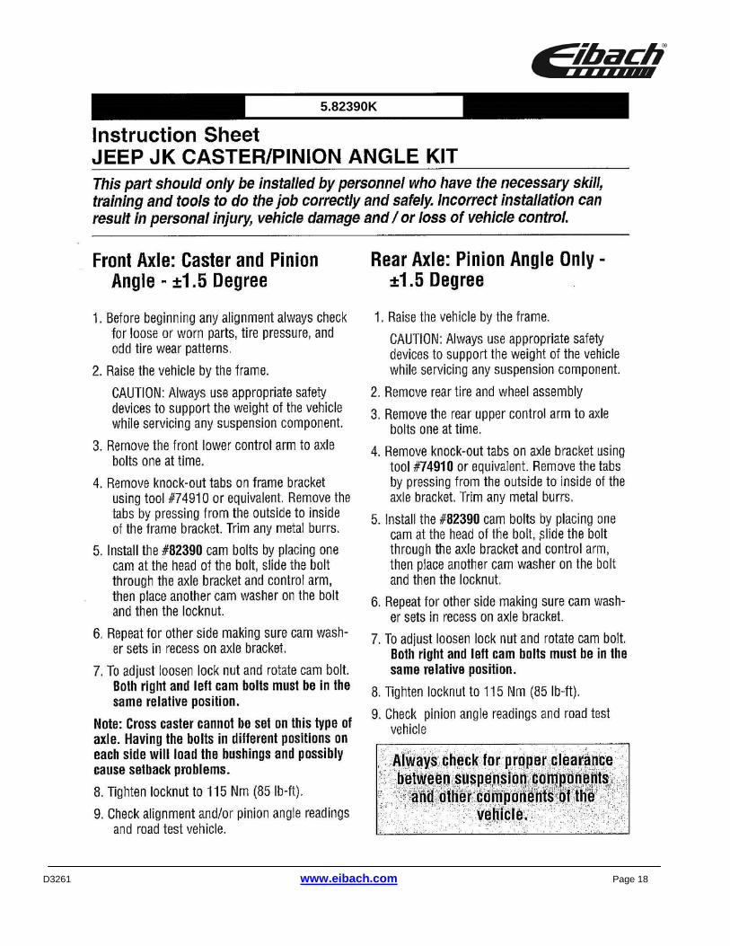
5.82390K

![jeep willys manual jeep militar [jipenet]](https://static.fdocuments.us/doc/165x107/5571f31d49795947648d86b9/jeep-willys-manual-jeep-militar-jipenet.jpg)