INSTALLATION INSTRUCTIONS - Kewauneekewaunee.com/uploadedFiles/Main/Home/Laboratory/Manuals... ·...
48
FOR WOOD AND STEEL FURNITURE IM-1107 INSTALLATION INSTRUCTIONS P.O. BOX 1842 STATESVILLE, NORTH CAROLINA 28687-1842 PHONE (704) 873-7202 FAX (800) 932-3296
-
Upload
hoangxuyen -
Category
Documents
-
view
220 -
download
0
Transcript of INSTALLATION INSTRUCTIONS - Kewauneekewaunee.com/uploadedFiles/Main/Home/Laboratory/Manuals... ·...

FOR
WOOD AND STEEL FURNITURE
IM-1107
INSTALLATION INSTRUCTIONS
P.O. BOX 1842 STATESVILLE, NORTH CAROLINA 28687-1842 PHONE (704) 873-7202 FAX (800) 932-3296

TABLE OF CONTENTS
INTRODUCTION...........................................................................................................page 1
DAMAGES IN SHIPMENT ...........................................................................................Page 4
UNPACKING AND LAYOUT OF FURNITURE .............................................................................page 6
INSTALLATION PROCEDURES AND ASSEMBLING INSTRUCTIONS FOR:
KEMSTRUTS.....................................................................................................page 6
KEMSTRUT TOP SUPPORTS (STEEL FURNITURE)......................................page 7
WALL MOUNTED STORAGE CABINETS .....................................................page 8
BASE CABINETS.............................................................................................page 9
COUNTER MOUNTED STORAGE CABINETS.............................................page 10
FULL HEIGHT STORAGE CABINETS..........................................................page 11
APRONS, APRON TABLE LEGS................................................................page 12
SINK PLUGS, TUB SINKS, CUP DRAINS ...................................................page 14
KEMRESIN TROUGHS...............................................................................page 17
WORK TOPS (KEMRESIN, KEMROCK, WOOD, STAINLESS STEEL) ......page 19
REAGENT RACKS (OPEN TYPE-WOOD & STEEL FURN.) ........................page 23
REAGENT RACKS (FACIA TYPE-WOOD & STEEL FURN.).........................page 23
REAGENT RACKS (STEEL FACIA TYPE-STEEL FURN.) ..........................page 23
FILLER PANELS & SCRIBE STRIPS (WOOD FURNITURE)
WALL & CENTER TABLE FILLER PANELS .................................page 26
TOE SPACE FILLERS .................................................................page 26
TOE SPACE FILLERS FOR WALL TABLE END ...........................page 27
WALL SCRIBE STRIPS ...............................................................page 27
KNEE SPACE PANELS................................................................page 28
FILLER PANELS & SCRIBE STRIPS (STEEL FURN.) ...........................page 29
PEGBOARDS .................................................................................................page 41
SELF-ADHESIVE VINYL BASE MOLDING....................................................page 42
FINAL ADJUSTMENT OF WOOD AND STEEL FURNITURE.................................page 43
SUGGESTED HARDWARE .................................................................................page 45

IM-1107 — page 1
INTRODUCTION
We are pleased that you have chosen Kewaunee quality for your new equipment, and it isour aim to give you the best available products. However, only proper installation will assureyour complete satisfaction. Therefore, we have prepared this guide to aid you in theinstallation of you equipment.
These instructions are for the installation of both wood and steel laboratory furnitureassemblies. Many of the instructions are the same for both types, while others are slightlydifferent and are noted accordingly. Please note the instructions contained in this booklet arebasic guide-lines and are not meant to cover every situation you may be faced with during theinstallation process. There will be project specific conditions, which will have to be addressedas they occur. In these instances please feel free to contact us and we will provide assistanceas necessary to allow you to complete your installation.
If there are any questions concerning installation or shipping problems, please contact theInstallation or Customer Service Department:
Kewaunee Scientific corporationP.O. Box 1842Statesville, NC 28687-1842Telephone (704) 873-7202FAX (800) 932-3296
Figure 1 shows an exploded view of a typical wood item of laboratory equipment. Figure 2 isthe assembled view of the same wood item. Figure 3 shows an exploded view of a typicalsteel item of laboratory equipment. Figure 4 is the assembled view of the same steel item.
Study these views carefully to fully acquaint yourself with the general scheme of laboratoryequipment construction and method of joining the units together to make up a complete itemof laboratory equipment.

IM-1107 — page 2
TYPICAL WOOD WALL AND FUME HOOD ASSEMBLY
Completed wood wall and fume hood assembly shown as an exploded view above. (Figure 2)
Exploded view of a typical wood wall and fume hood assembly showing the various partsrequired to make a complete laboratory furniture assembly. (Figure 1)
KEMRESIN CURB& TOP KEMRESIN TOP
KEMSTRUT(OPTIONAL)
REAR FILLER
CORNER GUARDS(OPTIONAL)
VINYL BASE MOLDING(OPTIONAL)
KEMRESIN TROUGH
REAGENT RACK
FUME HOOD
FIG. 1
FIG. 2
FILLER
IM-1107 — page 3
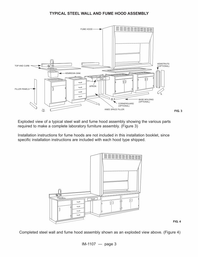
TYPICAL STEEL WALL AND FUME HOOD ASSEMBLY
Completed steel wall and fume hood assembly shown as an exploded view above. (Figure 4)
Exploded view of a typical steel wall and fume hood assembly showing the various partsrequired to make a complete laboratory furniture assembly. (Figure 3)
Installation instructions for fume hoods are not included in this installation booklet, sincespecific installation instructions are included with each hood type shipped.
FIG. 3
FIG. 4
TOP AND CURB
FILLER PANELS
KEMRESIN SINK
CORNERGUARD(OPTIONAL)
KNEE SPACE FILLER
BASE MOLDING(OPTIONAL)
KEMSTRUTS(OPTIONAL)
FUME HOOD
APRON

IM-1107 — page 4
DAMAGES IN SHIPMENT
IMPORTANT! PLEASE CHECK YOUR FURNITURE IMMEDIATELY UPON ARRIVAL!
Your furniture was accepted by the carrier in good condition and we urge you to inspect eachcarton for obvious damage to the contents before accepting it. If damage is found, insist thatthe driver note the damages on the freight bill and sign it. If, after uncrating the furniture, youfind concealed damage which was not apparent while the furniture was crated and the driverwas on the premises, contact the delivering carrier and request that they send arepresentative to make an inspection and prepare a concealed damage report. Theinspection must be made and a concealed damage report filed within fifteen (15) daysafter equipment is delivered. If the furniture is stored for period of time and then damage isdiscovered, trucking companies will not make or honor inspection reports.
NET F.O.B. FACTORY OR COLLECT SHIPMENTS - Customer is responsible for filing anyclaim for damage.
NET F.O.B. DESTINATION OR DELIVERED, INSTALLED JOBS - Shipper is responsible forfiling claim; however, proper documents must be forwarded to accomplish this.
PLEASE NOTE: We cannot make “No Charge” replacement on Prepaid Shipmentwithout proper damage documentation, ie. Freight Bills, Concealed Damage Reports,Inspection Reports, etc.
A. If the damage is such that it can be repaired on the job, we recommend that you have thedamage repaired and file your claim with the delivering carrier.
B. If the damage cannot be repaired locally, forward the noted freight bill or the concealeddamage report to Kewaunee, along with information giving the Item and Section Number ofthe part that is damaged. Please refer to installation prints for Item and Section Numbers foreach piece.
C. Damaged Tops: If damage occurs to tops, handle the same as damage to furniture. Apacking list covering the top material shipped to you is included in crate No. 1 of the originalshipment from the manufacturer. It will enable you to refer to the crate needed for each item.We realize that different items are sometimes packed in one crate, but like sizes force us todo this to reduce crating expense. Please refer to installation prints for piece marking ifbreakage or damage occurs.

IM-1107 — page 5
INSTALLATION
Your furniture is designed to make installation as easy as possible. All necessary scribestrips, fillers and other parts are furnished as ordered to allow you to achieve a complete andfinished laboratory installation. A parts list, screw list and hardware packing list are packed inhardware carton No. 1. Be sure to study your prints and packing lists carefully before startinginstallation of any furniture. This Installation Manual should also be read thoroughly beforeinstallation begins.
To aid you in segregating the units required to make up a complete item, each piece offurniture is identified with the Order Number, Part Number, Order Line Item Number andRoom and Elevation Number if requested/supplied. Hardware and plumbing fixtures arecartoned and the carton number can be found on the packing list. We recommend that youcheck the contents of each carton against the packing list and report any discrepancies toKewaunee promptly. We also recommend that the hardware and plumbing fixtures be lockedup until installed. Much time and effort can be saved if the units are segregated as they areunpacked and moved to the approximate location where they are to be installed. The packinglists should be carefully checked during the unpacking process to prevent loose items frombeing thrown away with the packing material. Any discrepancies between packing slip andmaterial actually received must be reported to Kewaunee within five(5) working days fromreceipt of shipment.
Each piece of furniture is identified with the Order Number, Part Number, Order Line ItemNumber and Room and Elevation Number if requested/supplied. On lower cabinets and apronsections, the identification will be on top of the unit or on a tag attached to the cabinet back.On other pieces, a tag will be attached or the Part Number shown on an exposed place onthe part. Refer to the installation prints and find the corresponding section or cabinet numberand place the cabinets in their approximate final location.
NOTE: Wood table tops are subject to warpage and end checking if stored improperlyprior to installation. They should be stored in a dry place on a level surface. Placewood strips between tops, at intervals of not more than four feet along the length ofthe top and crossway to the grain of the top. Cover tops with a protective covering tominimize damage.
NOTE: Before starting the actual casework installation, check the scribe and filler typeyou have against the trim section of this booklet, as it is necessary for some types oftrim to be installed prior to setting cabinetry.
IM-1107 — page 6
UNPACKING
To remove the unit from the shipping carton, open the top of the carton and then lay thecarton on its back. While holding the carton with one hand, pull the unit from the carton withthe other. Be careful not to damage the back of the unit. While the unit is still on its back,remove the shipping cleats from the bottom of the end panels if it is a wood unit. Stand theunit upright.
If units are blanket wrapped, carefully unwrap blanket and place blanket back in trailer. Onceunit is in approximate location it is to be installed, carefully remove any tape or strappingmaterial that is holding doors and drawers in place.
LAYOUT
When the units that form a complete item have been placed in the approximate locationwhere they are to be installed, arrange the units according to the installation drawings. Oncethis has been done, locate the high point in the floor by leveling across the tops of the units.When the high point has been determined, level to the starting point to determine the heightthe first unit must be set to maintain the level of the highest unit.
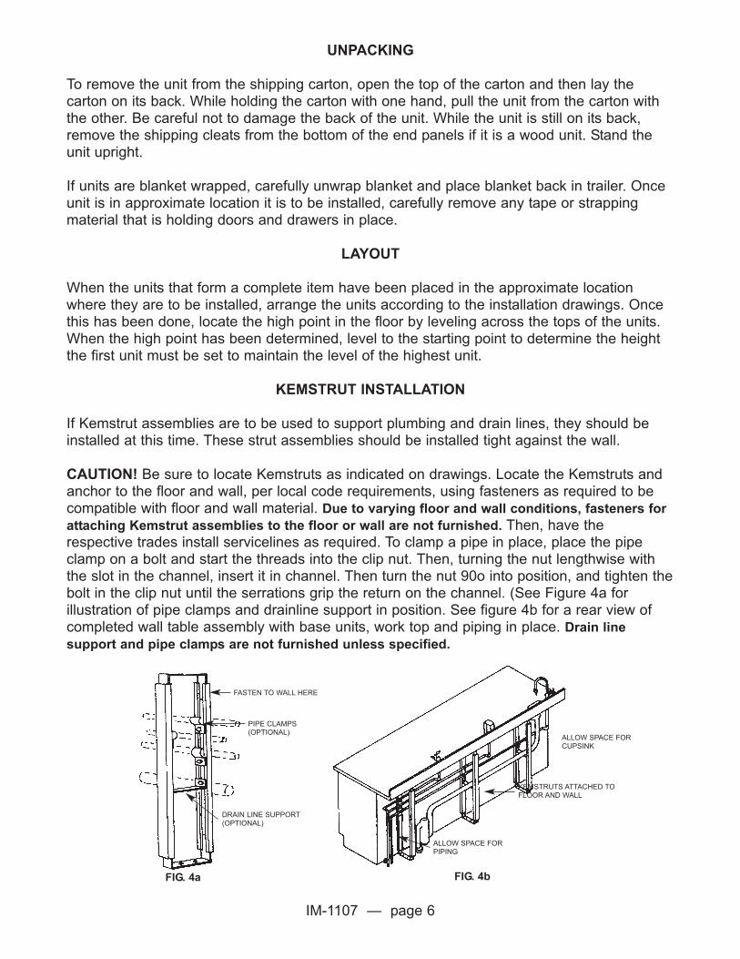
KEMSTRUT INSTALLATION
If Kemstrut assemblies are to be used to support plumbing and drain lines, they should beinstalled at this time. These strut assemblies should be installed tight against the wall.
CAUTION! Be sure to locate Kemstruts as indicated on drawings. Locate the Kemstruts andanchor to the floor and wall, per local code requirements, using fasteners as required to becompatible with floor and wall material. Due to varying floor and wall conditions, fasteners for
attaching Kemstrut assemblies to the floor or wall are not furnished. Then, have therespective trades install servicelines as required. To clamp a pipe in place, place the pipeclamp on a bolt and start the threads into the clip nut. Then, turning the nut lengthwise withthe slot in the channel, insert it in channel. Then turn the nut 90o into position, and tighten thebolt in the clip nut until the serrations grip the return on the channel. (See Figure 4a forillustration of pipe clamps and drainline support in position. See figure 4b for a rear view ofcompleted wall table assembly with base units, work top and piping in place. Drain line
support and pipe clamps are not furnished unless specified.
FIG. 4a FIG. 4b
FASTEN TO WALL HERE
PIPE CLAMPS(OPTIONAL)
DRAIN LINE SUPPORT(OPTIONAL)
ALLOW SPACE FORCUPSINK
KEMSTRUTS ATTACHED TOFLOOR AND WALL
ALLOW SPACE FORPIPING

IM-1107 — page 7
INSTALLATION OF KEMSTRUT TOP SUPPORT (STEEL)
Kemstrut Top Supports (No. K-0016-1A or K-0020-1A) are designed to be used in the cornerof L-shaped wall assemblies between adjacent cabinet runs to provide support for the worktop in the corner. This is used where the walls are of such construction that wood cleats orsteel angles cannot be used (or where the owner does not want anything attached to thewalls).
Assemble Kemstrut top support as illustrated in Figure 5.
Position and level cabinet units for Run "A". Measure and position cabinets correctly toaccommodate the necessary corner filler panel (see Figure 8).
As illustrated in Figure 9, position top support so one arm is flush with top of unit. Drill hole inrear top rail of unit (see Figure 6). Attach arm to unit with 1/4-20 x 3/4" Hex-Head bolt throughthe F-0169-02 nut (see Figure 7).
Position the F-0169-02 nut and level cabinet units for Run "B" (see Figure 10) and installationdrawings for proper "X" dimension. Attach other arm of the top support to the adjacent baseunit as illustrated. (see Figure 10).
Level along both legs of the furniture assembly and the top support. Adjustments in heightcan be made in the vertical leg of the top support if required.
FIG. 5 FIG. 6 FIG. 7
FIG. 8 FIG. 10FIG. 9
“A”2”
2”
“B”
“A”
“B”
“A”
“B”
KEMSTRUT
KEEP FLUSH END UPRIGHT
HEX HEAD BOLT1/4 - 20 X 3/4”
TOP BACK RAIL
F-0169-02NUT
K-0001-00 KEMSTRUT30” LONG K-0001-00 KEMSTRUT
K-0002-00KEMSTRUT
K-0017-00 SPACER F-0169-02 NUT
F-0169-02 NUT
F-0169-02 NUT ADJUSTSHORIZONTALLY
END UPRIGHT
TOP BACK RAIL
REMOVABLEBACK
HEX HEAD BOLTS1/4 - 20 X 3/4”
HEX HEAD BOLTS5/16 - 18 X 3/4”
K-0018-00 ANGLE FOOTMAY BE BOLTED TOFLOOR
MAKE VERTICALADJUSTMENTHERE FOR HEIGHTVARIATIONS OFLEVELED UNITS
NUT
3/8”
3/4”
13/16”
3/4”
3”1 3/8”

IM-1107 — page 8
WALL MOUNTED STORAGE CABINET INSTALLATION
Wall cabinets are hung by first attaching wood cleats to the wall and then securing thecabinets to the cleats with screws.
Determine the exact location of the cabinet and mark the desired location of the top leftcorner on the wall. Locate the cleats as shown in Figure 11. If more than one cabinet is to beinstalled in a row, make a chalk line on wall to line up the top of cleats. Make sure chalk lineis level.
Wood cleats (not supplied) shouldbe 3" to 4" wide and 3/4" thick. Cut them 6" less in length than the length of the cabinet.Mount the cleats as shown with heads of fasteners recessed flush with the face of the frontsof the cleats. Check the face of the cleats for plumb and, if necessary, insert shims betweenthe cleat and the wall to bring to plumb. Wood cleats should be secured to the wall usingappropriate fasteners as dictated by wall construction. (Due to varying wall material, fastenersare not furnished with the equipment).
Drill 9/32" hole in the back of the cabinet approximately 4" from each side of the cabinet andon the centerline of each cleat (4 holes). Set the cabinet in place, allowing the top rear rail torest on the tops of the wood cleats. Fasten it to the wood cleats using #12 x 1-1/4" oval headscrews with #12 countersunk washers.
If more than one wall cabinet is to be installed in a row, first install all cleats on the wall in thesame manner as described above. The cleat fronts should all lay in a straight line. High spotsin the wall should be leveled and low spots shimmed out to bring cleat fronts straight. (Checkwith straight edge). Improperly aligned cleats will cause misalignment on the face of thecabinets.
Screw the first wall-mounted storage cabinet to the cleats as described above. Next, placethe second cabinet into position. Fasten it to the first cabinet making sure the fronts andedges are in a straight line and the units are plumb. Then secure the cabinet to the wallcleats. Continue this process until all cabinets have been installed.
FIG. 11Mounting Cleats On The Wall
DESIRED LOCATION FOR TOPCORNER OF CABINET
6” LESS
THAN CABINET3”
11/8

IM-1107 — page 9
BASE CABINET INSTALLATION
When cabinets are located next to an adjacent wall, refer to the filler installation sectionbefore setting the first cabinet. If the first item is an apron, refer to apron installation. In a wall-to-wall configuration, both ends of the assembly must be addressed.
Move the first cabinet into its final location and bring it to the proper level. If the cabinet issteel, level with leveling bolts (Figure 12). If the cabinet is wood, bring to level with shims asshown in Figure 13. Where more than 10 shims are required to bring the cabinet up to level,use a piece of crating lumber as the bottom shim, and make final adjustments by placingshims on top of the crating lumber. If a wood shim is not allowed, cut short lengths ofKemstrut channel and use instead.
FIG. 13Placing Shims to Level Wood Cabinets
Set the next cabinet in place and level in the same manner. Fasten the second cabinet to thefirst, using screws provided.
Repeat the above process until all cabinets for the assembly have been installed. Be sure tocheck the alignment of the cabinet fronts and tops as you proceed to make sure they areflush and level. (see Figure 14 below).
FIG.14Checking Alignments of Cabinets Fronts and
the Leveling of Cabinets
FIG.12Leveling Bolt for Steel Cabinets
Leveling Bolt
ACCESSHOLE
Unit Bottom
2” X 2” STEEL SHAMS - ALLOW TO PROJECT 1” IF ATJOINT BETWEEN TWO CABINETS

IM-1107 — page 10
1. Counter mounted storage cabinets sit on top of a laboratorywork top, and are secured to the wall at the top with cleatssimilar to these used in wall mounted cabinet installation.
2. First position and level the base cabinet(s) andworksurface(s). Determine the exact location of the cabinet(s),and mark the desired location of the top left corner on the wall.Locate wood cleat 2" below and 3" to the right of this mark (seeFigure 15).
3. Wood cleat length should be 6" less than case length; widthshould be 3" to 4" and thickness not less than 3/4". The cleatsshould be secured to the wall using fasteners as appropriate forthe existing wall construction. Holes for the fasteners should becountersunk or counterbored to make heads flush with face ofcleat. (Due to various wall construction, fastening devices arenot included.) Wood cleats should be level and plumb. Highspots in the walls should be leveled and low spots shimmed outto make the cleats straight (check with straight edge and levelvertically and horizontally).
4. If more cabinets are to be installed in a row, make a chalk lineon wall to line up tops of wood cleats. Then, install all cleats on the wall in the same manner asdescribed above.
5. Remove sliding doors from cabinet(s). Drill enough 9/32" holes in back of cabinets to providefor securing to wood cleats at approximately 12" intervals along case length, locating the holesfrom the wood cleat positions.
6. Set the first cabinet in position on top of the laboratory work top and fasten it to the woodcleat using #12 x 1-1/4" oval head wood screws and #12 countersunk washer. Then, place thesecond cabinet in position and fasten it to the first cabinet making sure the fronts and edges ofthe cabinets are in a straight line. Then, screw the second cabinet to the wall cleat.Continue to proceed in this manner until all cabinets have been installed.
7. Install adjustable shelves in cabinets. Three adjustable shelves along with 12 shelf clips areprovided. Normally, shelves are installed to provide four approximately equal heightcompartments, but can be spaced as desired.
8. Clean glass on glazed doors.
9. Replace sliding doors in cabinets.
FIG. 15
3” 3”
2”
45”
84”
37”
35”
29” CLEAT
INSTALLING COUNTER MOUNTED STORAGE CABINETS
IM-1107 — page 11
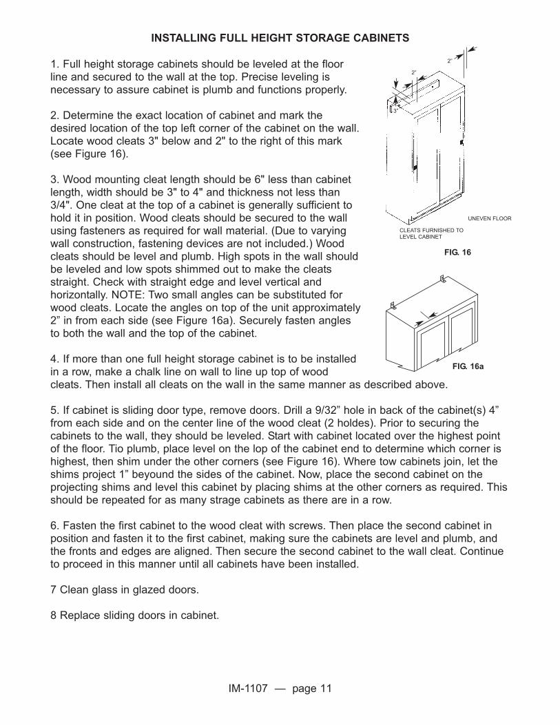
1. Full height storage cabinets should be leveled at the floorline and secured to the wall at the top. Precise leveling isnecessary to assure cabinet is plumb and functions properly.
2. Determine the exact location of cabinet and mark thedesired location of the top left corner of the cabinet on the wall.Locate wood cleats 3" below and 2" to the right of this mark(see Figure 16).
3. Wood mounting cleat length should be 6" less than cabinetlength, width should be 3" to 4" and thickness not less than3/4". One cleat at the top of a cabinet is generally sufficient tohold it in position. Wood cleats should be secured to the wallusing fasteners as required for wall material. (Due to varyingwall construction, fastening devices are not included.) Woodcleats should be level and plumb. High spots in the wall shouldbe leveled and low spots shimmed out to make the cleatsstraight. Check with straight edge and level vertical andhorizontally. NOTE: Two small angles can be substituted forwood cleats. Locate the angles on top of the unit approximately2” in from each side (see Figure 16a). Securely fasten anglesto both the wall and the top of the cabinet.
4. If more than one full height storage cabinet is to be installedin a row, make a chalk line on wall to line up top of woodcleats. Then install all cleats on the wall in the same manner as described above.
5. If cabinet is sliding door type, remove doors. Drill a 9/32” hole in back of the cabinet(s) 4”from each side and on the center line of the wood cleat (2 holdes). Prior to securing thecabinets to the wall, they should be leveled. Start with cabinet located over the highest pointof the floor. Tio plumb, place level on the lop of the cabinet end to determine which corner ishighest, then shim under the other corners (see Figure 16). Where tow cabinets join, let theshims project 1” beyound the sides of the cabinet. Now, place the second cabinet on theprojecting shims and level this cabinet by placing shims at the other corners as required. Thisshould be repeated for as many strage cabinets as there are in a row.
6. Fasten the first cabinet to the wood cleat with screws. Then place the second cabinet inposition and fasten it to the first cabinet, making sure the cabinets are level and plumb, andthe fronts and edges are aligned. Then secure the second cabinet to the wall cleat. Continueto proceed in this manner until all cabinets have been installed.
7 Clean glass in glazed doors.
8 Replace sliding doors in cabinet.
CLEATS FURNISHED TOLEVEL CABINET
UNEVEN FLOOR
FIG. 16
2”
2”
3”
INSTALLING FULL HEIGHT STORAGE CABINETS
FIG. 16a

IM-1107 — page 12
APRON INSTALLATION
Where an apron section is suspended between two cabinets or between wall and cabinet,fasten the apron to the cabinet. Be sure apron is set back 1/8" from the face of the unit forsteel and 1/4" for wood. When an apron is to be fastened to the wall, fasten as shown inFigure 17.
Be sure top of apron is flush and level with adjacent cabinet.
If the apron is supported by a cabinet on one end and legs on the other, install the legsbefore fastening the apron to the cabinet.
FIG. 17Apron Installed Between Wall and Cabinet
FIG. 18Leg Assembly Installation (Wood)
WALL3/4” X 3” X 21” WOODCLEAT FASTENEDTO WALL
APRON
LEVELING GLIDE AND T-NUT(OPTIONAL)
FASTEN APRON TOWOOD CLEAT W/ 4SCREWS
LEG WITH 3/8"-16 LEG BOLT,HEX NUT, AND WASHER
SPREADER(OPTIONAL)
MOD-EZ CLIP
CORNER BRACE
LEG SHOE WITHHOLD DOWN CLIP(OPTIONAL)
STRETCHER(OPTIONAL)
LEG ASSEMBLY INSTALLATION (WOOD)
Apron legs are shipped knocked down to conserve shipping space and are assembled asshown in Figure 18.
Lay the apron section bottom side up on a pad or other suitable protective material to protectthe top finish. Set the leg in position with the projecting leg bolts through the holes in thecorner brace. Install the washer and nut and tighten securely. Repeat this step until all legsfor a given apron section have been installed.

IM-1107 — page 13
LEG ASSEMBLY INSTALLATION (continued)
Where stretchers are used between legs, screw male half of Mod-ez clip to the leg using thethe screws provided and the pre-drill holes. Place stretcher in position and snap the twohalves of the Mod-ez clips together. (Female half of Mod-ez clip is installed on strecher atfactory.)
Repeat process with spreaders when spreaders are provided.
When legs have been installed, place vinyl leg shoes over the bottom of the leg, if provided,and turn apron right side up. Level with the leveling bolt or shims and fasten to floor with legholddowns if provided.
FIG. 19 LEG SHOE
WASHER PLATE 3/8”-16 NYLON HEX NUT
APRON ASSEMBLY
LEG ASSEMBLY
LEVELING BOLT
BOLT PLATE
LEG ASSEMBLY INSTALLATION (STEEL)
1. Slide leg shoes over bottom of legs. (Omit step if leg shoes are not provided.)2. Slide bolt plates into top of legs until bolt can be inserted through bolt hole.3. Align leg assembly with apron assembly and insert leg bolts into holes in apron.4. Place washer plates over ends of leg bolts from inside apron.5. Secure bolt plates, leg assembly, apron assembly, and washer plates with 3/8”-16 Nylok hex
nuts. Tighten nuts securely.6. Attach second leg assembly to other end of apron assembly if required.7. Adjust leveling bolts as needed to level assembly and slide leg shoes to bottom of legs.
INSTALLATION OF OPTIONAL SPREADER
1. Loosen Nylok hex nuts that secure legs to apron.2. Screw 1/4”-20 x 3/8” round head bolts into pre-tapped holes in leg assembly (2 perassembly). Screw all the way in and then back off two turns. 3. Slide spreader over bolt heads and seat. (Note: Top of spreader should be even with top ofstretchers on leg assembly.)4. Tighten all four spreader bolts.5. Re-tighten Nylok hex nuts that secure legs to apron.
IM-1107 — page 14
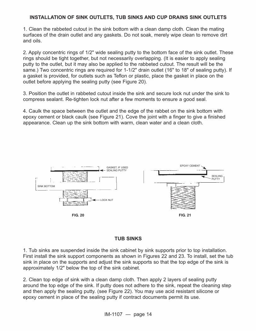
INSTALLATION OF SINK OUTLETS, TUB SINKS AND CUP DRAINS SINK OUTLETS
1. Clean the rabbeted cutout in the sink bottom with a clean damp cloth. Clean the matingsurfaces of the drain outlet and any gaskets. Do not soak, merely wipe clean to remove dirtand oils.
2. Apply concentric rings of 1/2" wide sealing putty to the bottom face of the sink outlet. Theserings should be tight together, but not necessarily overlapping. (It is easier to apply sealingputty to the outlet, but it may also be applied to the rabbeted cutout. The result will be thesame.) Two concentric rings are required for 1-1/2" drain outlet (16" to 18" of sealing putty). Ifa gasket is provided, for outlets such as Teflon or plastic, place the gasket in place on theoutlet before applying the sealing putty (see Figure 20).
3. Position the outlet in rabbeted cutout inside the sink and secure lock nut under the sink tocompress sealant. Re-tighten lock nut after a few moments to ensure a good seal.
4. Caulk the space between the outlet and the edge of the rabbet on the sink bottom withepoxy cement or black caulk (see Figure 21). Cove the joint with a finger to give a finishedappearance. Clean up the sink bottom with warm, clean water and a clean cloth.
TUB SINKS
1. Tub sinks are suspended inside the sink cabinet by sink supports prior to top installation.First install the sink support components as shown in Figures 22 and 23. To install, set the tubsink in place on the supports and adjust the sink supports so that the top edge of the sink isapproximately 1/2" below the top of the sink cabinet.
2. Clean top edge of sink with a clean damp cloth. Then apply 2 layers of sealing puttyaround the top edge of the sink. If putty does not adhere to the sink, repeat the cleaning stepand then apply the sealing putty. (see Figure 22). You may use acid resistant silicone orepoxy cement in place of the sealing putty if contract documents permit its use.
FIG. 20
LOCK NUT
SINK BOTTOM
GASKET, IF USEDSEALING PUTTY
FIG. 21
EPOXY CEMENT
SEALING PUTTY
IM-1107 — page 15
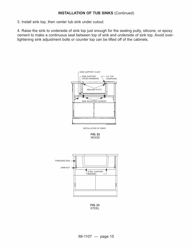
INSTALLATION OF TUB SINKS (Continued)
3. Install sink top, then center tub sink under cutout.
4. Raise the sink to underside of sink top just enough for the sealing putty, silicone, or epoxycement to make a continuous seal between top of sink and underside of sink top. Avoid over-tightening sink adjustment bolts or counter top can be lifted off of the cabinets.
SINK SUPPORT CLEAT
SINK SUPPORTCROSS MEMBERS
1/4” TOPOVERHANG
SEALING PUTTY
SINK ADJUSTING SCREWS
INSTALLATION OF SINKS
FIG. 22WOOD
FIG. 23STEEL
STEEL SUPPORTCHANNEL
JAMB NUT
THREADED ROD

IM-1107 — page 16
CUP DRAINS
Clean cup drain cutout and edges of cup sink with a clean damp cloth. Then install by layingtwo strips of sealing putty in the recess under the cup drain flange and one strip of sealingputty around perimeter of flange and edge of work top to seal against water leakage. (SeeFigure 24). If putty does not adhere to cup drain repeat the cleaning process. Acid resistantsilicone, or epoxy cement may be used in place of the sealing putty if contract documentspermit its use.
1 PIECE SEALING PUTTY
2 PIECES SEALING PUTTYUNDER FLANGE
FIG. 24

IM-1107 — page 17
INSTRUCTIONS FOR FIELD ASSEMBLY OF KEMRESIN TROUGHS
1. Assemble trough sections per drawing. Place sections bottom side up on a clean levelsurface and shim where necessary to assure a level trough and a square joint. (Stock troughsections carry numbers TR-1, TR-2, TR-3, TR-4 and TR-5.) (Special section lengths will carrya “J” part number.)
Joint clips and Epoxy Field Kit Cement are included, along with screws, bolts, etc. necessaryfor trough assembly. Locate these items before proceeding with the assembly.
2. Where trough sections join, ends have been sanded for better cement adhesion. If thisoperation was overlooked, please roughen ends with #80 or #100 grit emory cloth.
3.Clean ends of trough sections with a clean damp cloth.
4. When trough sections are ready to be joined, mix Epoxy Cement in accordance withdirections on tubes or cans. Mix cement on a clean, smooth flat surface and blend for severalminutes with a spatula. (Mix only enough for one joint at a time.) (The upturned bottom of thetrough makes a good mixing surface.) Temperature should be above 65 degrees to allowcement to adhere and set properly.
5. Spread the thoroughly mixed cement to both ends of the surface to be joined and forcesections of trough together.
TOP
END SINK
USE ONE OR MORE RIBBONSTO SEAL AROUND TROUGHS
TROUGH
FIG. 25ILLUSTRATION OF KEMSTRUT SUPPORT RACK
BEFORE INSTALLATION OF TROUGH
FIG. 26ILLUSTRATION OF TROUGH AFTER INSTALLATION
SUPPORT SPACER
PIPE CLAMP DETAIL
POSITION OF SUPPORTSPACER ON WALLTABLES HAVINGTROUGHS
METHOD OFCLEARINGBASEBOARD
BASEBOARD
BOLT ANDNUT SECTION
ON CENTER TABLES HAVING ATROUGH POSITION SPACER ASSHOWN
ON ITEMS NOT HAVING A TROUGHADJUST SPACER AS SHOWN
INSTALLING TROUGHS
Adjust supporting “Kemstruts” (Figure 25) to a height to allow trough to be 3/8” below the topof the cabinets. Set trough on Kemstruts to approximate final location. Clean bottom ofcounter top and top of trough with alcohol and a clean cloth. Apply sealing putty to top edgeof trough. You are now ready to set tops. When tops are in place, shim trough tight againstunderside of top to ensure proper seal. Acid resistant silicone may be used in place of sealingputty if contract documents permit its use.

IM-1107 — page 18
INSTRUCTIONS FOR FIELD ASSEMBLY OF KEMRESIN TROUGHS (Continued)
6. Place formed steel trough clips into grooves adjacent to the joint and tap down lightly toapply pressure to the joint. Alternate tapping of the clips from one side of the trough to theother to bring even pressure on the joint. When a tight joint has been secured, clean excessadhesive from trough bottom with warm water and clean cloth. Complete other joints followingthe same procedure.
7. Turn the trough over to its normal useable position, using one man for each trough section.Elevate trough on blocking to avoid cement adhering to a flat surface. Clean cement frominside of trough joint area with water or solvent. Clean up must be done while cementis still soft. The cleaning process should be completed within 15 to 30 minutes ofapplication.
8. Examine joint or joints to make sure the sides are aligned. If not, clamp top edge of thetrough with a “C” clamp until cement sets. Recheck to assure all excess cement has beencleaned from inside surfaces.
9. We recommend that cement be placed in grooves adjacent to side clips, therebypermanently cementing them in place.
10. The completed trough should remain undisturbed overnight at normal room temperature65 degrees or above. If temperature is below 65 degrees, some method of increasingtemperature is necessary to promote a strong joint. Epoxy cements will not cure properlyat temperatures below 55 degrees F.
11. Cement will attain about one-half strength overnight at normal room temperature. Placingthe assembled trough on the permanent supports should be done carefully, using one manper section when handling.
If you have specific problems or questions during the above operation, please contactour factory.

IM-1107 — page 19
INSTALLATION OF WORK TOPS
Before installing work tops, make sure base cabinets, aprons, wall supports, and Kemstrutsare level. Lay all top sections in place, checking carefully with the installation drawings tomake sure the proper sections are used. Check all fixture holes and sink cutouts for propersize and location. Make sure each piece is evenly supported. If the base units have beenproperly leveled, the top sections will lie smoothly, with top surfaces flush. If you have a slightvariation in top thickness from one section to another, make sure the variation is at thebottom of top. Top surfaces should be level.
KEMERESIN TOPS
Before placing top sections on the support structure, scuff sand edge to be cemented andwipe each edge with a clean cloth dampened in lacquer thinner or equal solvent. Start fromone end and shift top sections to provide a 3” space between first and second section.CAUTION: These solvents are extremely volatile and must not be used near heat orflame. You must also be in a well ventilated area when using these solvents.
You are now ready to mix the two part Epoxy cement. Follow directions on cans carefully andonly mix as much as can be used in 15 or 20 minutes. The two components must bethoroughly mixed for proper adhesion. The mixing process usually takes 5 minutes or longerdepending on room temperature. Adding extra hardener will not speed up the curingprocess. Do not attempt to cement tops together if a minimum room temperature of55oF is not being maintained.
Cover the joint edge of the top sections with enough cement to make a resonable width jointseam. Align sections and slide working sections back and forth, front to back until proper jointis attained. This will force out surplus cement. The same result can be obtained by the use ofpipe clamps if walls do not interfere. If clamps are used, leave them in place overnight toensure proper cement set-up. (Place a piece of cardboard under joint at front to keep cementoff of casework, remove cardboard after cement has set up.)
After the joint is made, clean it by scraping excess cement from surface. (Use a putty knifewithout burrs to avoid scratching surface). Wipe joint and adjacent areas with a clean clothslightly dampened with water. Do not let cement harden before cleaning or it will beimpossible to remove. Continue with other joints using procedures described above.
If necessary, a small “C” clamp can be used at the front overhang at a joint to align adjacenttop sections vertically. Do not put cement in the joint at that point. Cement should be addedlater after the rest of the joint has set and clamp is removed.

IM-1107 — page 20
CURB
CEMENT
FIG.27
CEMENT
WORK SURFACE
KEMERESIN TOPS (continued)
Use a small amount of Epoxy cement at the four corners of the base unit to secure tops. Useextreme care not to get cement on the finished surface.
After the entire top is completed, clean with detergent and water, wipe dry and apply a coat ofany furniture polish. Apply polish sparingly and wipe with a dry cloth to achieve the desiredluster.
The installer is to carefully clean all foreign debris and dust and carefully polish countertopsand work surfaces. The installer is to provide protection to the countertops and work surfacesafter installation and cleaning by carefully covering the entire countertop surface with heavygauge clean construction paper, clean corrugated cardboard or other suitable materials andtaping the protective material to the countertop, along the entire contertop perimeter, withpainters’ masking tape. Warning signs should then be place on the top with the protectivematerials.
NOTE: Do not store tops on side or bottom. Please follow recommended storageinsturctions on outside of cartons.
NOTE: After tops have been installed for approximately 24 hours the epoxy cement injoints will shrink. Each joint should be re-grouted to give the top a smooth surfaceacross each joint.
WORK SURFACE

IM-1107 — page 21
WOOD TOPS
Joints are made in wood and plastic laminate tops as shown in Figure 29. Lay the tops on theunit with the ends about 9” apart and cover the end surface of one top with Ribbon FlatMastic or silicone sealer-end to end so the routs for the joint fastener are accessible. Installone OP-0310-00 fastener (Figure 30) in each rout pair in each section of top. Using a 3/8”wrench, tighten each fastener until you have hairline joints in tops. Place tops in theirpermanent location. Secure to understructure as required. (see Figure 31)
NUT
TIE ROD
NUT
FASTENERS
FIG. 29METHOD OF JOINTING WOOD OR
PLASTIC LAMINATE TOPS
FIG. 31METHOD OF ANCHORING WOOD, PLASTIC
LAMINATE, OR STAINLESS STEEL TOPS
FIG. 30CROSS SECTION THROUGH TOP
ILLUSTRATING FASTENER POSITION
TOP JOINT
1/2”
1/2
”
1 1
/4”
1/2” 1 1/2”1”
3”
1”

IM-1107 — page 22
STAINLESS STEEL TOPS
Curbing along back and sides are made as an integral part of the top.
Whenever it becomes necessary to make the top in two or more sections due to length ofroom or room conditions, the tops are fastened together by a mechanical joint concealedbelow the working surface of the adjoining top. The 1” x 1” angles, which are welded to theedges of the top, are bolted securely with 1/4” - 20 bolts. This allows the tops to beassembled as one complete top.
To install tops, place blocks on top of base units (units should be located in their permanentpositions). Lay each section of top on the blocks. With adjoining tops in position, bolt togetherat the mechanical joint. After all mechanical joints are securely fastened, blocks are removedand top is lowered into its permanent position.
Tops are now fastened to units with screws and hold down clips in Figure 31. Use #10 x 1”round head wood screws for this purpose.

IM-1107 — page 23
INSTALLATION OF STEEL REAGENT RACKS
Reagent racks are shipped knocked down and are to be assembled during the installationprocess. A partial exploded view of a typical reagent rack is shown in Figure 32. This viewshows all of the parts in their relative positions. Figure 32 also indicates the proper screws touse for rack assembly. Uprights and facia panels (if applicable) should be carefully positionedand fastened to the worksurface as shown in figures 32a and 32b. Facia panels are attachedwith #6 1/4” binding head screws. If possible, it is more convenient to have pipes and conduitinstalled for services by the appropriate trades before attaching the reagent shelf.ing head screws (See Figures 42 and 43).
FIG. 32
FIG. 32a FIG. 32b
REAGENT SHELF
A
A
A
C
D
E
D
E
D
E
C
C
A
A
A
A
A
A
A A
A
A
A
AB
B
B
A
W-0067-00 HOLD DOWNANGLES
SEE FIGURE 32a
SEE FIGURE 32B
W-0021-1A UPRIGHT
W-0068-00 CHANNEL
W-0068-00 CHANNEL
W-0014-0A UPRIGHT
F-0050-00 MOLDING
W-0013-0A UPRIGHT
KM-0371-0A COVERPLATE
WORK SURFACE
F-0357-00 COVER BUTTON
FACIA PANEL
C
C
C
C
C
C
C
A. #8 X 5/8” ROUND HEAD SCREWB. #6 X 1/4” BINDING HEAD SCREWC. #6 X 3/8” JACKSON HEAD SCREWD. #12 X 3/4” ROUND HEAD SCREWE. #12 X 1/4” PLATE WASHER
C
CC
CD
E
D
E
D
E
D
E

IM-1107 — page 24
INSTALLATION OF STEEL REAGENT RACKS (Continued)
1. Install center table (or wall table) base units and tops as previously described.
2. Mount W-0067-00 hold down angles and W-0068-00 channels on tabletop. For Kemrock orKemresin tops, epoxy cement should be used for mounting these angles and channels. Iftops are wood, holes will have to be drilled in the top for mounting (see Figures 33 and 34 forhole locations). Drill 3/4” deep holes with a No. 17 drill bit. Attach angles and channels totable top with 1/4” plate washers and #12 x 3/4” round head screws.
3. Put rubber moldings in position on underside of reagent rack uprights, and set uprights inposition over the hold down angles and channels on the tabletop.
4. Figures 33 and 34 show two configurations of wall table reagent racks. Figure 33 illustratesuprights with service cutouts for pipes and conduit. Figure 34 illustrates intermediateadjustable shelving. Be certain that uprights are located correctly to accommodate the lengthof the adjustable shelves.
5. Locate complete reagent rack in exact position desired and fasten reagent rack upright tothe hold down angles and channels previously installed. Holes are provided in the uprights forthis purpose. Use a No. 33 drill bit to drill matching holes in the hold down angles andchannels. Fasten in position with #6 x 3/8” Jackson head screws.
6. Mount all plumbing and/or electrical fixtures and make final piping and electrical conduitconnections. Cover all unused holes with plug buttons and/or electrical cover plates. (Holeson rear facia panels of wall table reagent racks need not be covered.) In most cases, fixtureinstallation, piping, and wiring are to be performed by other trades concurrently with caseworkinstallation.
7. Attach ledge to top of reagent rack. Set ledge in exact position and drill 3/4” deep pilotholes into underside of ledge through punched holes in top flanges of facia panels andreagent rack uprights. Use a #29 drill bit for this function. If ledge comes in two or moresection, cement sections together before attaching it to the reagent rack.
FIG. 33REAGENT RACK UPRIGHTS WITH SERVICE CUTOUTS
FIG. 34REAGENT RACK WITH ADJUSTABLE SHELVES
IM-1107 — page 25
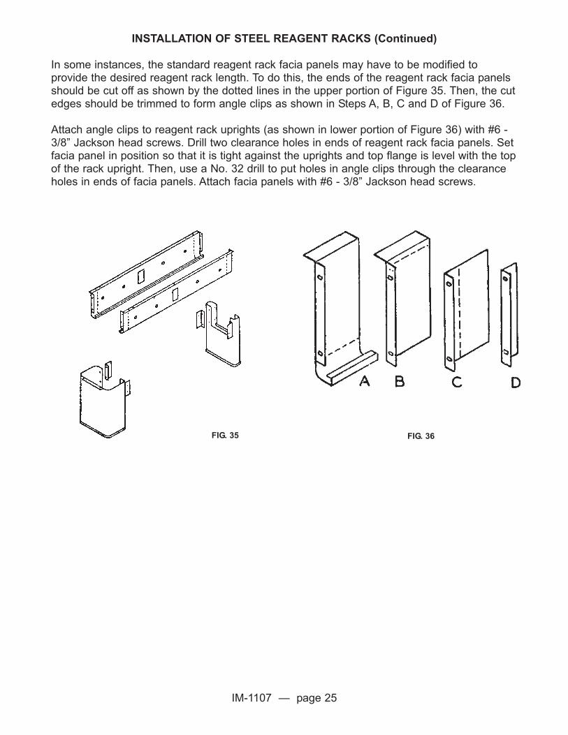
INSTALLATION OF STEEL REAGENT RACKS (Continued)
In some instances, the standard reagent rack facia panels may have to be modified toprovide the desired reagent rack length. To do this, the ends of the reagent rack facia panelsshould be cut off as shown by the dotted lines in the upper portion of Figure 35. Then, the cutedges should be trimmed to form angle clips as shown in Steps A, B, C and D of Figure 36.
Attach angle clips to reagent rack uprights (as shown in lower portion of Figure 36) with #6 -3/8” Jackson head screws. Drill two clearance holes in ends of reagent rack facia panels. Setfacia panel in position so that it is tight against the uprights and top flange is level with the topof the rack upright. Then, use a No. 32 drill to put holes in angle clips through the clearanceholes in ends of facia panels. Attach facia panels with #6 - 3/8” Jackson head screws.
FIG. 35 FIG. 36

IM-1107 — page 26
INSTALLATION OF FILLER PANELS AND SCRIBE STRIPS FOR WOOD
When all plumbing and/or wiring has been completed, install the filler panels and scribe strips.In general, filler panels and scribe strips are used to fill in any openings left between cabinetunits and the wall, or open spaces between cabinets. Careful installation of these items willimprove the appearance of the furniture, and aid in keeping the laboratory clean.
WALL & CENTER TABLE FLUSH FILLER PANELS
Plumbing space wall and center table filler panels are normally 7” to 8” wide, and arefurnished with two 3/4” x 3/4” mounting cleats. They are installed flush as illustrated in Figure37. For a wall table filler, attach one cleat to the wall, and the other cleat to the rear of thebase unit with #9 1-1/4” flat head wood screw. (Use a No. 5/32” drill). The filler panel isattached to the cleats with #6 round head wood screws. For a center table filler attach the twocleats to the rear of the base units with a #9 - 1 1/4” flat head wood screws. The filler panel isattached to the cleats with #6 - 3/4” round head wood screws. Be sure to attach the rearcleat to the wall before cases are set.
INTERMEDIATE OVERLAPPING FILLER PANELS
Overlapping intermediate filler panels are installed overlapping the front edges of adjacent units(Figure 38a and 39). Install by placing the toe space filler panel in position and drill the edges ofthe units with a No. 1/8” bit for #6 round head wood screw.
CENTER TABLEWOOD
TOP VIEW
WOODFILLER
8 3/4” WIDE
FIG. 37
FIG. 38a FIG. 39

IM-1107 — page 27
OVERLAPPING WALL TABLE END FILLER
Overlapping end filler panels are installed overlapping the edge of a unit on one side and buttsagainst the wall on the other side. Wall table end filler panels (Figure 38b & 40) are providedwith one 3/4” cleat to attach to the wall. The filler panel is then put into position and the edgesof the unit and the cleat are drilled with a 1/8” drill for #6 flat head wood screws.
WOOD UNITFILLER
TOE SPACEFILLER
3/4” X 3/4”WOOD CLEAT
FIG. 40TOE SPACE WALL & TABLE FILLER
FIG. 41HORIZONTAL SECTION OF A TOE SPACE
WALL TABLE
FIG. 38b

IM-1107 — page 28
WALL SCRIBE STRIP INSTALLATION
To scribe a strip to the wall, place one edge on the cabinet and the other edge against thewall. Now take a pair of dividers and adjust them to the widest opening between the edge ofthe strip and the wall surface. When this measurement has been obtained, start at the top ofthe strip with one point of the dividers against the wall and the other point held against thesurface of the strip, and move the dividers the entire length of the strip (Figure 43).
The wall profile will then be scribed on the strip. Using sheet metal shears (for steel) or handsaw (for wood) cut the strip along the scribed line. The strip will then fit smoothly against thewall surface. Attach the strip to the cabinet as previously described for Flush or OverlappingFiillers.
INSTALLATION OF KNEE SPACE PANELS (WOOD)
Knee space panels are used to close an opening between aprons, between units or units andwalls. To install, first mount knee space panel cleats on the adjacent base units. Positioncleats as shown in Figure 44. Secure to base unit end with a #9 - 1 1/4” flat head woodscrew. Next set knee space panel in position against the cleats and attach with #6 - 1 1/4”round head wood screw, (Figure 45).
WALL SCRIBING METHODFIG. 43
FILLER STRIP
UNIT UNIT
APRON FRONT
KNEE SPACEPANEL
WORKSURFACE
SCRIBED LINE
DIVIDERS
WALL
CABINET
# 6X1-1/4”R.H. WOOD
SCREWS
UNIT
# 9X1-1/4”F.H. WOODSCREWS
APRON FRONT
WORKSURFACE
CLEAT3/4” X 3/4”
FIG. 44 FIG. 45

IM-1107 — page 29
INSTALLATION OF STEEL SCRIBES AND FILLERS
NOTE: FIGURES FORTY-SIX (46) THROUGH SIXTY-EIGHT (68) RELATE TO STEEL TRIMPIECES ONLY
FIG. 46TO CLOSE OPENING BETWEEN WALL AND FRONT OF
ADJACENT BASE UNITS
FIG. 47TO CLOSE OPENING BETWEEN TWO ADJACENT
BASE UNITS
L-5073-00
L-5073-01
L-5181-01
L-5181-00
L-0329-00SHIP LOOSE
(1) #75-0015-0PSHIP LOOSE
(1) #75-0015-0PSHIP LOOSESCREW TO UNITSNOT TO TOESPACE

IM-1107 — page 30
INSTALLATION OF STEEL SCRIBES AND FILLERS
FIG. 48TO CLOSE OPENING BETWEEN TWO ADJACENT
BASE UNITS JOINED AT RIGHT ANGLES
FIG. 49TO CLOSE OPENING BETWEEN WALL AND REAR OF
ADJACENT BASE UNITS
NOTE: ATTACH TRIM TO BACK OF UNIT PRIOR TOSETTING UNIT IN PLACE
L-5163-00
(2) #75-0015-0P
REAR OF UNIT
“B”
“A”
TH
IS S
IDE
TO
WA
LL

IM-1107 — page 31
INSTALLATION OF STEEL SCRIBES AND FILLERS
FIG. 50TO CLOSE OPENING BETWEEN TWO ADJACENT
BASE UNITS INSTALLED BACK TO BACK
FIG. 51TO CLOSE OPENING BELOW APRONS AND APRON
RAILS

IM-1107 — page 32
INSTALLATION OF STEEL SCRIBES AND FILLERS
FIG. 54TO FINISH BACKS OF WALL CABINETS FLUSH
FIG. 55TO CLOSE OPENING BETWEEN WALL AND FRONT OF
ADJACENT WALL CABINET

IM-1107 — page 33
INSTALLATION OF STEEL SCRIBES AND FILLERS
FIG. 52TO CLOSE AND FINISH PIPE CHASE AREA BEHIND BASE
UNITS ON SINGLE SIDED ISLANDS AND PENINSULAS(MUST BE USED WITH FINISHED BACK PANELS).
FIG. 53TO COVER BACKS OF BASE UNITS EXPOSED TO VIEW.FINISHED BACK MOUNTING DETAILS FOR WALL UNITS
AND FULL HEIGHT UNITS SAME AS BASE UNITS

IM-1107 — page 34
INSTALLATION OF STEEL SCRIBES AND FILLERS
FIG. 56TO CLOSE OPENING BETWEEN FRONTS OF TWO
ADJACENT WALL CABINETS
FIG. 57TO CLOSE OPENING BETWEEN TWO ADJACENT
WALL CABINETS JOINED AT RIGHT ANGLES
FRONT OF UNIT
FRONT OF UNIT
IM-1107 — page 35
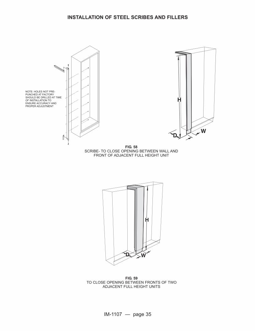
INSTALLATION OF STEEL SCRIBES AND FILLERS
FIG. 58SCRIBE- TO CLOSE OPENING BETWEEN WALL AND
FRONT OF ADJACENT FULL HEIGHT UNIT
FIG. 59TO CLOSE OPENING BETWEEN FRONTS OF TWO
ADJACENT FULL HEIGHT UNITS
NOTE: HOLES NOT PRE-PUNCHED AT FACTORYSHOULD BE DRILLED AT TIMEOF INSTALLATION TOENSURE ACCURACY ANDPROPER ADJUSTMENT

IM-1107 — page 36
INSTALLATION OF STEEL SCRIBES AND FILLERS
FIG. 60TO CLOSE OPENING BETWEEN TWO ADJACENT FULL
HEIGHT UNITS JOINED AT RIGHT ANGLES
FIG. 61TO CLOSE OPENING BETWEEN WALL AND REAR OF
ADJACENT FULL HEIGHT UNITS

IM-1107 — page 37
INSTALLATION OF STEEL SCRIBES AND FILLERS
FIG. 62TO COVER BACKS OF FULL HEIGHT UNITS EXPOSED TO VIEW
FIG. 63WALL MOUNTED OR FULL HEIGHT UNIT-SLOPING TOP

IM-1107 — page 38
INSTALLATION OF STEEL SCRIBES AND FILLERS
FIG. 64WALL MOUNTED CORNER UNIT-SLOPING TOP
FIG. 65WALL MOUNTED UNIT OR FULL HEIGHT UNIT-
CEILING ENCLOSURE
WHEN REQUIRED USESPLICE TO CONNECTADJACENT FILLER
ALLOW CEILING ANGLES TORUN AS LONG AS POSSIBLECOVERING FILLER JOINTS

IM-1107 — page 39
INSTALLATION OF STEEL SCRIBES AND FILLERS
FIG. 66WALL MOUNTED UNIT OR FULL HEIGHT UNIT-
SLOPING TOP EXTENSION
FIG. 67WALL MOUNTED UNIT OR FULL HEIGHT UNIT-
SLOPING TOP CORNER

IM-1107 — page 40
INSTALLATION OF STEEL SCRIBES AND FILLERS
FIG. 68WALL MOUNTED CORNER UNIT
CEILING ENCLOSURE
WHEN REQUIRED, USE SPLICETO CONNECT ADJACENT FILLER
WHEN ADJACENT ENCLOSURESARE PRESENT ALLOW CEILINGANGLES TO RUN AS LONG ASPOSSIBLE TO COVER FILLERJOINTS
WHEN REQUIRED, USE EXTRAANGLE MATERIAL SUPPLIED TOFINISH END PANEL TO CEILING

IM-1107 — page 41
PEGBOARD INSTALLATION
Pegboards are fastened to the wall with no less than four (4) fasteners. Fasteners are notfurnished due to varying wall conditions. Holes should be drilled in the pegboards using a 1/4”masonry drill. The actual location within pegboard is determined by wall conditions.
When pegboards are installed directly over a table top or curb, seal the joint between the topand pegboard with sealing putty or silicone.
PEGBOARD
SET PEGBOARD ON 2 RIBBONSAND COMPRESS
WALL SINKLEDGE
FIG. 69
FIG. 70

IM-1107 — page 42
SELF-ADHESIVE VINYL BASE MOLDING
1. Room temperature during installation should be 75 to 85 degrees F. It is recommended thatthe base molding be removed from the carton and conditioned to this temperature range priorto actually installing. Good bonding is achieved even if the mounting surface is cold, providedthe cove base is between 75 and 85 degrees F.
2. Do not use a solvent of any kind to activate or intensify the initial tack of the adhesive.Solvents tend to deteriorate permanent bonding ability.
3. To ensure a good, tight, permanent bond, the surface should be sound and free of dirt, lint,old paint, etc. In most instances, simply brushing or wiping the surface will be sufficient toclean well enough. If water is used, the mounting surface must be allowed to dry thoroughly,as dampness will prevent bonding of the adhesive.
4. Remove release paper from only one length of base molding at a time during theinstallation process.
5. Base molding should be positioned so that the toe or bottom edge of the entire length restson the floor. Start with one end and press against the wall or unit toe space, holding balanceof the length away from the mounting surface. Then start from the point of initial contact andpress the molding against the surface working toward the trailing end.
6. For succeeding lengths, spot in place tightly against the butt edge of the previous length,keeping the toe or bottom edge parallel with and resting on floor, then install as describedabove.
7. After the base molding is in place, press the top edge firmly against the mounting surfaceall the way across the length, working back along the length toward the beginning point orjoint with adjacent lengths.
8. Press, rub or roll from center to bottom along the length to assure good contact with themounting surface at all points. Work back toward joint with preceding length to assure tight fit.
9. After base molding has been applied as close to outside or inside corner as possible,position corner clip and fasten with black oxidized drive screws or nails on wood cabinets.
10. To install corner clips on steel units, drill proper size hole in base rail and install withproper sheet metal corner clip screw.
NOTE: SPECIAL CARE SHOULD BE TAKEN NOT TO STRETCH BASE MOLDINGDURING INSTALLATION.
NOTE: ROOM TEMPERATURE DURING INSTALLATION MUST BE AT LEAST 65OF ORMOLDING WILL NOT BOND TO THE CABINET OR WALL.

IM-1107 — page 43
FINAL ADJUSTMENT OF WOOD FURNITURE
1. Place all removable back panels in place.
2. If it has been necessary to run conduit on plumbing pipe through plumbing space opening,the panels should be cut to fit around these pipes and reinstalled.
3. All shelves in base cabinets should have hold downs removed and shelves installed ontheir supports.
4. Each item of furniture should be cleaned inside and out and final adjustment made asfollows:
a. All wood drawer assemblies are pre-fitted to their respective openings at the factoryduring the installation process they are sometimes removed from their originallocations and installed elsewhere. When this happens they mayl not operate freely.Should this condition exist, remove the drawer and find the drawer originally fitted tothe opening and install it there. This should relieve any binding and allow the drawer towork properly. This procedure should be repeated as many times as necessary until alldrawers are returned to their original location.
b. When doors bind or are uneven, it is usually an indication the units have settled outof level. Cabinets should be re-leveled. Once this is done, door should align and workfreely. Re-level by adding or removing shims as needed.
c. In some instances, it may be necessary to adjust a hinge to level doors. If this is thecase, the hinge should not be moved more than 1/16”.
d. When adjusting doors, it may be necessary to readjust the magnetic catches. Thiscan be done by loosening mounting screw and moving catch forward or backward, asneeded.
FINAL ADJUSTMENT OF STEEL FURNITURE
As a final installation step, each item of furniture should be cleaned and final adjustmentsmade. Adjust drawers to work freely in the case channels without excessive play. Note thatthe drawer head end of the drawer channels have a locking tab. Heads may be adjusted byloosening screws in taps and tapping with a rubber mallet until head is centered in opening.

IM-1107 — page 44
FINAL ADJUSTMENT OF STEEL FURNITURE (Continued)
When doors (or drawers) bind as shown in Figure 71, it usually is a sign that the cabinet hassettled out of level. Cabinet should be re-leveled by raising or lowering one corner of the unitwith the adjustment bolts.
Touch-up paint, if provided, can be used to touch up any scratches or mars in the finish thatoccurred during handling and installation. When scratches do occur, take a fine camel’s hairbrush and fill in all scratches and mars with paint, taking care not to get paint on thesurrounding area. Once this has been done, paint on touched up area should be dried forapproximately 5 minutes with either a standard heat gun or hair dryer. This restores the acidresistance to the touch up paint.
INSTALLATION OF FUME HOODS
Fume hood installation instructions, operating instructions, maintenance instructions, etc., arecovered in separate publications. Therefore, this information is not included in this booklet.Please contact Kewaunee Scientific Corp., (704) 873-7202 for any information of this type.
IF DOORS BINDAS SHOWN
FIG. 71
IM-1107 — page 45
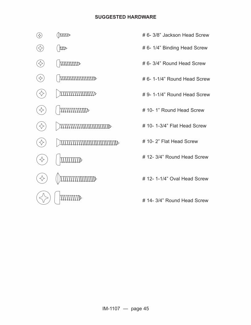
# 6- 3/8” Jackson Head Screw
# 6- 1/4” Binding Head Screw
# 6- 3/4” Round Head Screw
# 6- 1-1/4” Round Head Screw
# 9- 1-1/4” Round Head Screw
# 10- 1” Round Head Screw
# 10- 1-3/4” Flat Head Screw
# 10- 2” Flat Head Screw
# 12- 3/4” Round Head Screw
# 12- 1-1/4” Oval Head Screw
# 14- 3/4” Round Head Screw
SUGGESTED HARDWARE

Copyright 2007 IM-1107 Printed in U.S.A. WSII-10/07
P.O.Box 1842 Statesville, NC 28687-1842
(704) 873-7202 (704) 873-5840
E-mail: [email protected]
www.kewaunee.com
C