INSTALLATION INSTRUCTIONS IMPERVIA SLIDING … · Exterior 1D ' & ( ) D. Fold the water resistive...
12
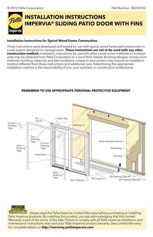
Part Number: 803V0102 © 2012 Pella Corporation INSTALLATION INSTRUCTIONS IMPERVIA ® SLIDING PATIO DOOR WITH FINS Installation Instructions for Typical Wood Frame Construction. These instructions were developed and tested for use with typical wood frame wall construction in a wall system designed to manage water. These instructions are not to be used with any other construction method. Installation instructions for use with other construction methods or multiple units may be obtained from Pella Corporation or a local Pella retailer. Building designs, construction methods, building materials, and site conditions unique to your project may require an installation method different from these instructions and additional care. Determining the appropriate installation method is the responsibility of you, your architect, or construction professional. Sill Flashing Tape #2 Sill Flashing Tape #1 Water Resistive Barrier Sheathing Framing Nailing Fin Sill Support Top Flashing Tape Fin Corner Door Top Door Bottom Side Flashing Tape Interlocker Side Flashing Tape Corner Flashing Tape Corner Flashing Tape REMEMBER TO USE APPROPRIATE PERSONAL PROTECTIVE EQUIPMENT Always read the Pella Impervia Limited Warranty before purchasing or installing Pella Impervia products. By installing this product, you are acknowledging that this Limited Warranty is part of the terms of the sale. Failure to comply with all Pella Impervia installation and maintenance instructions may void your Pella Impervia product warranty. See Limited Warranty for complete details on http://warranty.pellaimpervia.com.
Transcript of INSTALLATION INSTRUCTIONS IMPERVIA SLIDING … · Exterior 1D ' & ( ) D. Fold the water resistive...
Part Number: 803V0102© 2012 Pella Corporation
INSTALLATION INSTRUCTIONSIMPERVIA® SLIDING PATIO DOOR WITH FINS
Installation Instructions for Typical Wood Frame Construction.
These instructions were developed and tested for use with typical wood frame wall construction in a wall system designed to manage water. These instructions are not to be used with any other construction method. Installation instructions for use with other construction methods or multiple units may be obtained from Pella Corporation or a local Pella retailer. Building designs, construction methods, building materials, and site conditions unique to your project may require an installation method different from these instructions and additional care. Determining the appropriate installation method is the responsibility of you, your architect, or construction professional.
Sill Flashing Tape #2Sill Flashing Tape #1
Water Resistive Barrier
Sheathing
Framing
Nailing Fin
Sill Support
TopFlashingTape
FinCorner
Door Top
Door Bottom
SideFlashingTape
Interlocker
SideFlashingTape
CornerFlashingTape
CornerFlashingTape
REMEMBER TO USE APPROPRIATE PERSONAL PROTECTIVE EQUIPMENT
Always read the Pella Impervia Limited Warranty before purchasing or installing Pella Impervia products. By installing this product, you are acknowledging that this Limited Warranty is part of the terms of the sale. Failure to comply with all Pella Impervia installation and maintenance instructions may void your Pella Impervia product warranty. See Limited Warranty for complete details on http://warranty.pellaimpervia.com.

YOU WILL NEED TO SUPPLY:Cedar or Impervious shims/spacers (12 to 20)
2" galvanized roofing nails (1/4 lb.)
Closed cell foam backer rod/sealant backer (24 to 32 ft.)
Pella® SmartFlash™ foil backed butyl window and door flashing tape or equivalent
Pella Window and Door Installation Sealant or equivalent high quality, multi-purpose sealant (2 to 3 tubes per door)
Low expansion, low pressure polyurethane insulating window and door foam sealant - DO NOT use high pressure or latex foams
Pella aluminum sill support or 2 x 4 wood blocking
Interior trim and/or jamb extensions (15 to 40 ft.)
FOR MULLION APPLICATIONS:
I bar joining connector
Pella silicone foam tape
Mullion end plug (2)
Field applied fins (4 pcs. per unit)
Head drip fin (Vertical Mullion applications only)
TOOLS REQUIRED:Tape measure
Level
Square
Hammer
Stapler
Hacksaw
Sealant gun
Scissors or Utility knife
Screwdrivers
(#2 Phillips with 8" shaft and small flat blade)
Rubber mallet
Drill
Installation will require two or more persons for safety reasons.
A. Confirm the opening is plumb and level. Ensure the bottom of the rough opening does not slope towards the interior.
Note: It is critical the bottom is level.
4th cut: Make a 6" cut up from each top corner at a 45o angle to allow the water resistive barrier to be lapped over the fin at the head of the door.
1st cut
2nd cut
3rd cut
Water Resistive Barrier
1C
B. Confirm the door will fit the opening. Measure all four sides of the opening to make sure it is 1/2" larger than the door in width and height. Measure the width at the top, bottom and center. Measure the height at the far left side, the far right side and in the center.
Note: Solid wood blocking of 1-1/2" or more is required around the perimeter of the opening. Fix any problems with the rough opening before proceeding.
C. Cut the water resistive barrier.
1 ROUGH OPENING PREPARATION
1A
1B
1C
Exterior
1D
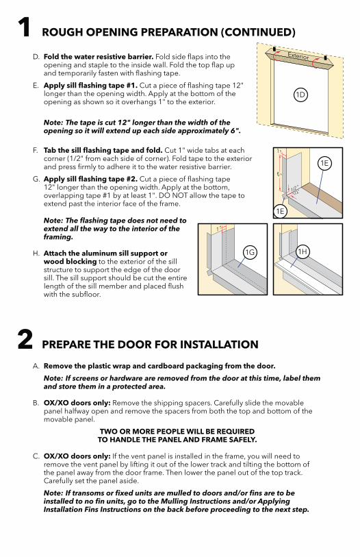
D. Fold the water resistive barrier. Fold side flaps into the opening and staple to the inside wall. Fold the top flap up and temporarily fasten with flashing tape.
E. Apply sill flashing tape #1. Cut a piece of flashing tape 12" longer than the opening width. Apply at the bottom of the opening as shown so it overhangs 1" to the exterior.
Note: The tape is cut 12" longer than the width of the opening so it will extend up each side approximately 6".
F. Tab the sill flashing tape and fold. Cut 1" wide tabs at each corner (1/2" from each side of corner). Fold tape to the exterior and press firmly to adhere it to the water resistive barrier.
G. Apply sill flashing tape #2. Cut a piece of flashing tape 12" longer than the opening width. Apply at the bottom, overlapping tape #1 by at least 1". DO NOT allow the tape to extend past the interior face of the frame.
Note: The flashing tape does not need to extend all the way to the interior of the framing.
H. Attach the aluminum sill support or wood blocking to the exterior of the sill structure to support the edge of the door sill. The sill support should be cut the entire length of the sill member and placed flush with the subfloor.
A. Remove the plastic wrap and cardboard packaging from the door.
Note: If screens or hardware are removed from the door at this time, label them and store them in a protected area.
B. OX/XO doors only: Remove the shipping spacers. Carefully slide the movable panel halfway open and remove the spacers from both the top and bottom of the movable panel.
TWO OR MORE PEOPLE WILL BE REQUIRED TO HANDLE THE PANEL AND FRAME SAFELY.
C. OX/XO doors only: If the vent panel is installed in the frame, you will need to remove the vent panel by lifting it out of the lower track and tilting the bottom of the panel away from the door frame. Then lower the panel out of the top track. Carefully set the panel aside.
Note: If transoms or fixed units are mulled to doors and/or fins are to be installed to no fin units, go to the Mulling Instructions and/or Applying Installation Fins Instructions on the back before proceeding to the next step.
1D
1E
1E
1H1G
1 ROUGH OPENING PREPARATION (CONTINUED)
2 PREPARE THE DOOR FOR INSTALLATION
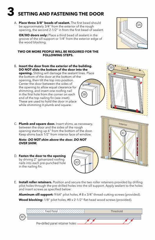
A. Place three 3/8" beads of sealant. The first bead should be approximately 3/4" from the exterior of the rough opening, the second 2-1/2" in from the first bead of sealant.
OX/XO doors only: Place a third bead of sealant in the groove of the sill support or 1/4" from the exterior edge of the wood blocking.
TWO OR MORE PEOPLE WILL BE REQUIRED FOR THE FOLLOWING STEPS.
B. Insert the door from the exterior of the building. DO NOT slide the bottom of the door into the opening. Sliding will damage the sealant lines. Place the bottom of the door at the bottom of the opening, then tilt the top into position. Center the door between the sides of the opening to allow equal clearance for shimming, and insert one roofing nail in the first hole from the corner on each end of the top nailing fin (see inset). These are used to hold the door in place while shimming it plumb and square.
C. Plumb and square door. Insert shims, as necessary, between the door and the sides of the rough opening starting up 6" from the bottom of the door. Keep shims back 1/2" from interior face of window.
Note: DO NOT shim above the door. DO NOT OVER SHIM.
Interior
3C
D. Fasten the door to the opening by driving 2" galvanized roofing nails into each pre-punched hole in the nailing fin.
E. Install roller retainers. Position and secure the two roller retainers provided by drilling pilot holes through the pre-drilled holes into the sill support. Apply sealant to the holes and insert screws as specified below:
Aluminum sill support: 9/64" pilot holes, # 8 x 3/4" thread-cutting screws (provided).
Wood blocking: 1/8" pilot holes, #8 x 2-1/2" flat-head wood screws (provided).
3 SETTING AND FASTENING THE DOOR
3A
3B
3B
3C
3D
3E
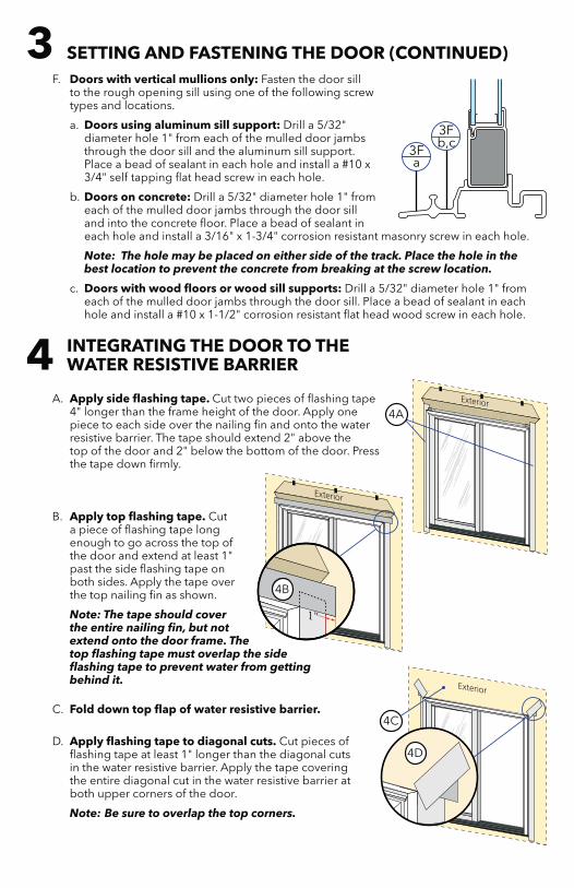
A. Apply side flashing tape. Cut two pieces of flashing tape 4" longer than the frame height of the door. Apply one piece to each side over the nailing fin and onto the water resistive barrier. The tape should extend 2" above the top of the door and 2" below the bottom of the door. Press the tape down firmly.
B. Apply top flashing tape. Cut a piece of flashing tape long enough to go across the top of the door and extend at least 1" past the side flashing tape on both sides. Apply the tape over the top nailing fin as shown.
Note: The tape should cover the entire nailing fin, but not extend onto the door frame. The top flashing tape must overlap the side flashing tape to prevent water from getting behind it.
C. Fold down top flap of water resistive barrier.
D. Apply flashing tape to diagonal cuts. Cut pieces of flashing tape at least 1" longer than the diagonal cuts in the water resistive barrier. Apply the tape covering the entire diagonal cut in the water resistive barrier at both upper corners of the door.
Note: Be sure to overlap the top corners.
F. Doors with vertical mullions only: Fasten the door sill to the rough opening sill using one of the following screw types and locations.
a. Doors using aluminum sill support: Drill a 5/32" diameter hole 1" from each of the mulled door jambs through the door sill and the aluminum sill support. Place a bead of sealant in each hole and install a #10 x 3/4" self tapping flat head screw in each hole.
b. Doors on concrete: Drill a 5/32" diameter hole 1" from each of the mulled door jambs through the door sill and into the concrete floor. Place a bead of sealant in each hole and install a 3/16" x 1-3/4" corrosion resistant masonry screw in each hole.
Note: The hole may be placed on either side of the track. Place the hole in the best location to prevent the concrete from breaking at the screw location.
c. Doors with wood floors or wood sill supports: Drill a 5/32" diameter hole 1" from each of the mulled door jambs through the door sill. Place a bead of sealant in each hole and install a #10 x 1-1/2" corrosion resistant flat head wood screw in each hole.
3Fa
3Fb,c
3 SETTING AND FASTENING THE DOOR (CONTINUED)
4 INTEGRATING THE DOOR TO THE WATER RESISTIVE BARRIER
4A
4B
4C
4D
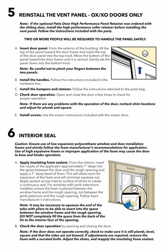
Caution: Ensure use of low expansion polyurethane window and door installation foams and strictly follow the foam manufacturer’s recommendations for application. Use of high expansive foams or improper application of the foam may cause the door to bow and hinder operation.
A. Apply insulating foam sealant. From the interior, insert the nozzle of the applicator approximately 1" deep into the space between the door and the rough opening and apply a 1" deep bead of foam. This will allow room for expansion of the foam and will minimize squeeze out. Apply sealant across interior surface of shims to create a continuous seal. For windows with jamb extensions installed, ensure the foam is placed between the window frame and the rough opening, not between the jamb extension and the rough opening. Follow foam manufacturer's instructions.
Note: It may be necessary to squeeze the end of the tube with pliers to be able to insert into the space between the window frame and the rough opening. DO NOT completely fill the space from the back of the fin to the interior face of the opening.
B. Check the door operation by opening and closing the door.
Note: If the door does not operate correctly, check to make sure it is still plumb, level, square and that the sides are not bowed. If adjustments are required, remove the foam with a serrated knife. Adjust the shims, and reapply the insulating foam sealant.
Note: If the optional Patio Door High Performance Panel Retainer was ordered with the sliding door, install the high performance roller retainer before installing the vent panel. Follow the instructions included with the parts.
TWO OR MORE PEOPLE WILL BE REQUIRED TO HANDLE THE PANEL SAFELY.
A. Insert door panel. From the exterior of the building, tilt the top of the panel toward the door frame and insert the top of the door panel into the top track. Move the bottom of the panel toward the door frame until it is vertical. Gently set the panel down into the bottom track.
Note: Be careful not to pinch your fingers between the two panels.
B. Install the handles. Follow the instructions included in the hardware box.
C. Install the bumpers and retainer. Follow the instructions attached to the parts bag.
D. Check door operation. Open and close the door a few times to check for proper operation.
Note: If there are any problems with the operation of the door, recheck shim locations and adjust for plumb and square.
E. Install screen. Use the screen instructions included with the screen door.
5A
5 REINSTALL THE VENT PANEL - OX/XO DOORS ONLY
6 INTERIOR SEAL
6A
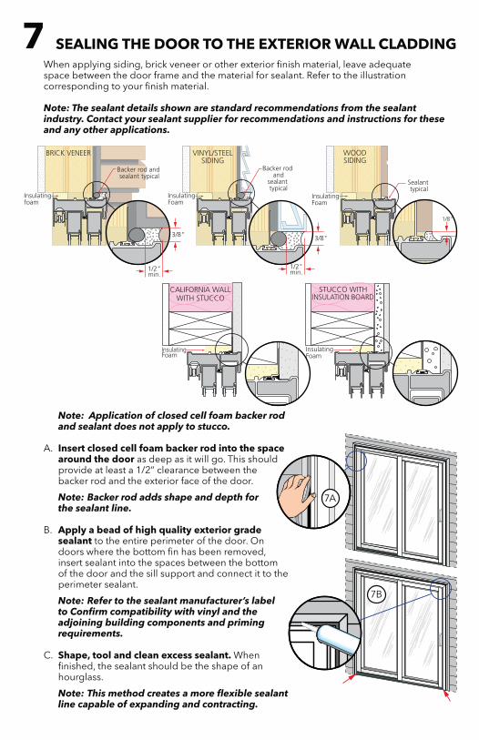
Note: Application of closed cell foam backer rod and sealant does not apply to stucco.
A. Insert closed cell foam backer rod into the space around the door as deep as it will go. This should provide at least a 1/2” clearance between the backer rod and the exterior face of the door.
Note: Backer rod adds shape and depth for the sealant line.
B. Apply a bead of high quality exterior grade sealant to the entire perimeter of the door. On doors where the bottom fin has been removed, insert sealant into the spaces between the bottom of the door and the sill support and connect it to the perimeter sealant.
Note: Refer to the sealant manufacturer’s label to Confirm compatibility with vinyl and the adjoining building components and priming requirements.
C. Shape, tool and clean excess sealant. When finished, the sealant should be the shape of an hourglass.
Note: This method creates a more flexible sealant line capable of expanding and contracting.
When applying siding, brick veneer or other exterior finish material, leave adequate space between the door frame and the material for sealant. Refer to the illustration corresponding to your finish material.
Note: The sealant details shown are standard recommendations from the sealant industry. Contact your sealant supplier for recommendations and instructions for these and any other applications.
7 SEALING THE DOOR TO THE EXTERIOR WALL CLADDING
7A
7B
MULLING INSTRUCTION
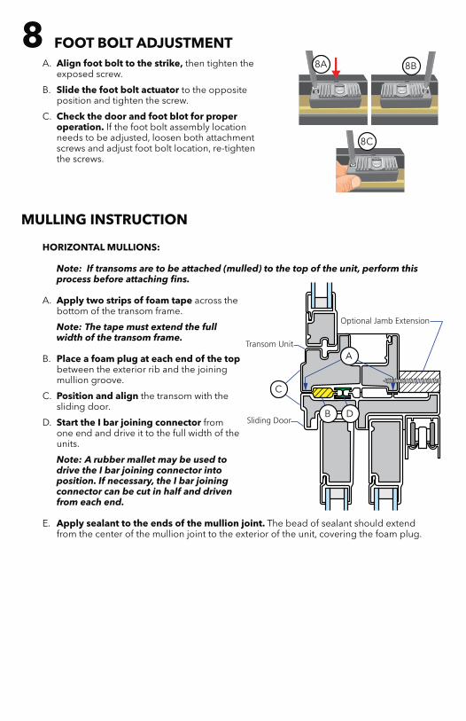
HORIZONTAL MULLIONS:
Note: If transoms are to be attached (mulled) to the top of the unit, perform this process before attaching fins.
A. Apply two strips of foam tape across the bottom of the transom frame.
Note: The tape must extend the full width of the transom frame.
B. Place a foam plug at each end of the top between the exterior rib and the joining mullion groove.
C. Position and align the transom with the sliding door.
D. Start the I bar joining connector from one end and drive it to the full width of the units.
Note: A rubber mallet may be used to drive the I bar joining connector into position. If necessary, the I bar joining connector can be cut in half and driven from each end.
E. Apply sealant to the ends of the mullion joint. The bead of sealant should extend from the center of the mullion joint to the exterior of the unit, covering the foam plug.
A. Align foot bolt to the strike, then tighten the exposed screw.
B. Slide the foot bolt actuator to the opposite position and tighten the screw.
C. Check the door and foot blot for proper operation. If the foot bolt assembly location needs to be adjusted, loosen both attachment screws and adjust foot bolt location, re-tighten the screws.
8A 8B
8C
8 FOOT BOLT ADJUSTMENT
8A 8B
8C
A
C
B D
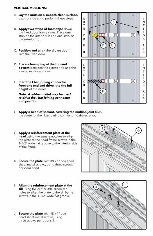
VERTICAL MULLIONS:
A. Lay the units on a smooth clean surface, exterior side up to perform these steps.
B. Apply two strips of foam tape down the fixed door frame sides. Place one strip on the interior rib and one strip on the exterior rib.
C. Position and align the sliding door with the fixed door.
D. Place a foam plug at the top and bottom between the exterior rib and the joining mullion groove.
E. Start the I bar joining connector from one end and drive it to the full height of the doors.
Note: A rubber mallet may be used to drive the I bar joining connector into position.
F. Apply a bead of sealant, covering the mullion joint from the center of the I bar joining connector to the exterior.
G. Apply a reinforcement plate at the head using the square notches to align the plate to the head frame screws in the 1-1/2" wide flat groove to the interior side of the frame.
H. Secure the plate with #8 x 1" pan head sheet metal screws, using three screws per door head.
I. Align the reinforcement plate at the sill using the center 3/8" diameter holes to align the plate to the sill frame screws in the 1-1/2" wide flat groove.
J. Secure the plate with #8 x 1" pan head sheet metal screws, using three screws per door sill.
B
D E
F
HG
JI
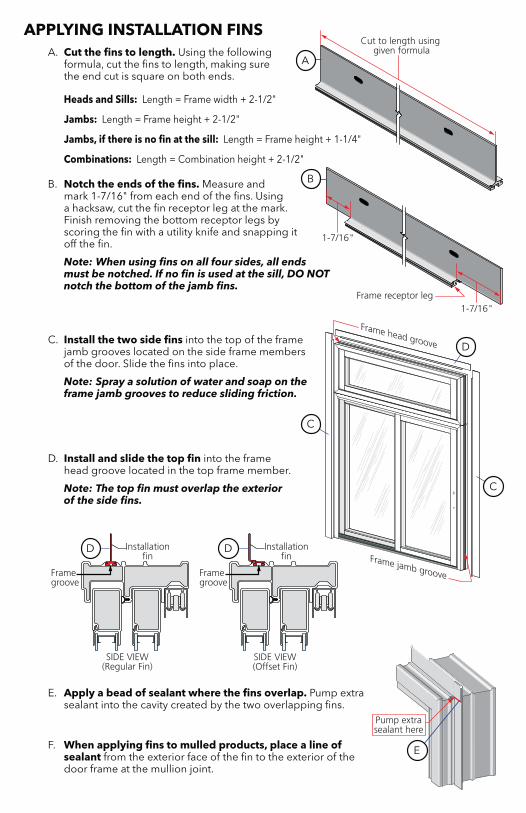
APPLYING INSTALLATION FINSA. Cut the fins to length. Using the following
formula, cut the fins to length, making sure the end cut is square on both ends.
Heads and Sills: Length = Frame width + 2-1/2"
Jambs: Length = Frame height + 2-1/2"
Jambs, if there is no fin at the sill: Length = Frame height + 1-1/4"
Combinations: Length = Combination height + 2-1/2"
B. Notch the ends of the fins. Measure and mark 1-7/16" from each end of the fins. Using a hacksaw, cut the fin receptor leg at the mark. Finish removing the bottom receptor legs by scoring the fin with a utility knife and snapping it off the fin.
Note: When using fins on all four sides, all ends must be notched. If no fin is used at the sill, DO NOT notch the bottom of the jamb fins.
C. Install the two side fins into the top of the frame jamb grooves located on the side frame members of the door. Slide the fins into place.
Note: Spray a solution of water and soap on the frame jamb grooves to reduce sliding friction.
D. Install and slide the top fin into the frame head groove located in the top frame member.
Note: The top fin must overlap the exterior of the side fins.
E. Apply a bead of sealant where the fins overlap. Pump extra sealant into the cavity created by the two overlapping fins.
F. When applying fins to mulled products, place a line of sealant from the exterior face of the fin to the exterior of the door frame at the mullion joint.
B
D
E
A
C
C
D D
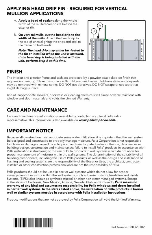
APPLYING HEAD DRIP FIN - REQUIRED FOR VERTICAL MULLION APPLICATIONS
A. Apply a bead of sealant along the whole width of the mulled composite behind the exterior rib.
B. On vertical mulls, cut the head drip to the width of the units. Attach the head drip to the top of units aligning the ends and seal to the frame on both ends.
Note: The head drip may either be riveted to the fin or installed when the unit is installed. If the head drip is being installed with the unit, perform Step A at this time.
FINISHThe interior and exterior frame and sash are protected by a powder coat baked-on finish that requires no painting. Clean this surface with mild soap and water. Stubborn stains and deposits may be removed with mineral spirits. DO NOT use abrasives. DO NOT scrape or use tools that might damage surface.
Use of inappropriate solvents, brickwash or cleaning chemicals will cause adverse reactions with window and door materials and voids the Limited Warranty.
CARE AND MAINTENANCECare and maintenance information is available by contacting your local Pella sales representative. This information is also available on www.pellaimpervia.com.
IMPORTANT NOTICEBecause all construction must anticipate some water infiltration, it is important that the wall system be designed and constructed to properly manage moisture. Pella Corporation is not responsible for claims or damages caused by anticipated and unanticipated water infiltration; deficiencies in building design, construction and maintenance; failure to install Pella® products in accordance with Pella installation instructions; or the use of Pella products in wall systems which do not allow for proper management of moisture within the wall systems. The determination of the suitability of all building components, including the use of Pella products, as well as the design and installation of flashing and sealing systems are the responsibility of the Buyer or User, the architect, contractor, installer, or other construction professional and are not the responsibility of Pella.
Pella products should not be used in barrier wall systems which do not allow for proper management of moisture within the wall systems, such as barrier Exterior Insulation and Finish Systems, (EIFS) (also known as synthetic stucco) or other non-water managed systems. Except in the states of California, New Mexico, Arizona, Nevada, Utah, and Colorado, Pella makes no warranty of any kind and assumes no responsibility for Pella windows and doors installed in barrier wall systems. In the states listed above, the installation of Pella products in barrier wall or similar systems must be in accordance with Pella installation instructions.
Product modifications that are not approved by Pella Corporation will void the Limited Warranty.
Part Number: 803V0102
B
A

This page left blank intentionally.