Installation Instructions Hustler 6-BTV Trap Vertical · Installation Instructions Hustler 6-BTV...
13
6748-1 This PDF Courtesy Of Installation Instructions Hustler 6-BTV Trap Vertical ASSEMBLY 1. Check the package contents against the parts list on page 2. 2. WARNING. Installation of this product near power lines is dangerous. For your safety, read the enclosed warnings and follow the installation directions. 3. Prepare split lead on coax in accordance with figures 2 and 3. RG-8/U coax is recommend- ed. (See decoupling information, page 12). 4. Install lugs on coax as shown in figure 4 and weatherproof with electrical tape. 5. Install coax feed line and radials (if needed) as shown in figure 7. Coax length is notcritical. 6. After making all connections it is recommended you spray the bracket assembly with a heavy protective coating such as Krylon clear spray coating.. 7. Attach the 10-meter trap to the 72 in. tube using a stainless steel clamp #3152-8. Set di- mension “A” as indicated in the table in figures 5 and 6. 8. Assemble one of the 20 in. tubes on top of the 10-meter trap using a clamp. Place the 15-meter trap on top of the 20 in. tube and set dimension “B” (see table figures 5 and6). Repeat this step with another 20 in. tube and install the 20-meter trap. Set dimension “C”. 9. Put the 24 in. tube above the 20-meter trap. Place the 30-meter trap on it, using a clamp. Set dimension “D” (figures 5 and 6). 10. There is no trap for 40 meters. The 40-meter section consists of a 36 in. tube with a thread- ed stud on the upper end. Install the 40-meter tube on the top of the 30-meter trap. Set dimension “E” (figures 5 and 6). 11. Screw on the 75/80-meter resonator at the top of the 40-meter tube and adjust the tip rod in accordance with figure 8.NOTE: The Hustler RM-75S and RM-80S resonators are the same. Tip rod length is the only difference. 12. Place the antenna on the bracket assembly and set dimension “A”, using the last clamp. Page 1
Transcript of Installation Instructions Hustler 6-BTV Trap Vertical · Installation Instructions Hustler 6-BTV...

6748-1
This PDF Courtesy Of
Installation InstructionsHustler 6-BTV Trap Vertical
ASSEMBLY
1. Check the package contents against the parts list on page 2.2. WARNING. Installation of this product near power lines is dangerous. For your safety,
read the enclosed warnings and follow the installation directions.3. Prepare split lead on coax in accordance with figures 2 and 3. RG-8/U coax is recommend-
ed. (See decoupling information, page 12).4. Install lugs on coax as shown in figure 4 and weatherproof with electrical tape.5. Install coax feed line and radials (if needed) as shown in figure 7. Coax length is notcritical.6. After making all connections it is recommended you spray the bracket assembly with a
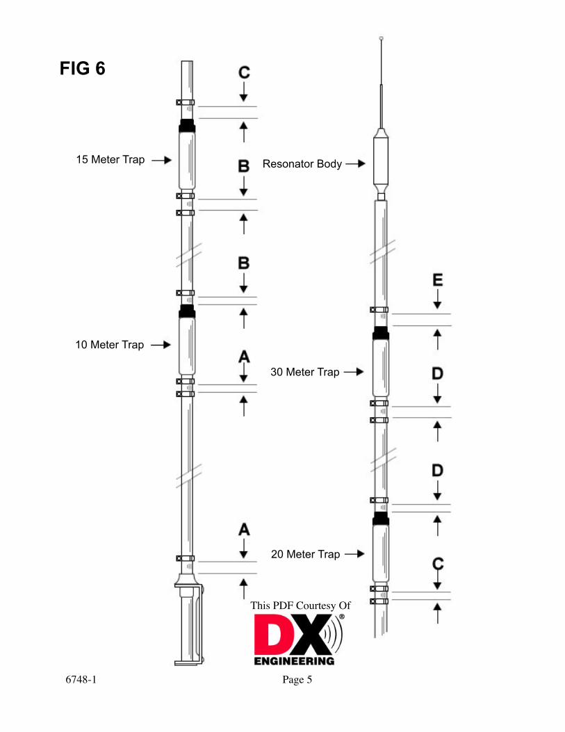
heavy protective coating such as Krylon clear spray coating..7. Attach the 10-meter trap to the 72 in. tube using a stainless steel clamp #3152-8. Set di-
mension “A” as indicated in the table in figures 5 and 6.8. Assemble one of the 20 in. tubes on top of the 10-meter trap using a clamp. Place the
15-meter trap on top of the 20 in. tube and set dimension “B” (see table figures 5 and6). Repeat this step with another 20 in. tube and install the 20-meter trap. Set dimension “C”.
9. Put the 24 in. tube above the 20-meter trap. Place the 30-meter trap on it, using a clamp. Set dimension “D” (figures 5 and 6).
10. There is no trap for 40 meters. The 40-meter section consists of a 36 in. tube with a thread-ed stud on the upper end. Install the 40-meter tube on the top of the 30-meter trap. Set dimension “E” (figures 5 and 6).
11. Screw on the 75/80-meter resonator at the top of the 40-meter tube and adjust the tip rod in accordance with figure 8.NOTE: The Hustler RM-75S and RM-80S resonators are the same. Tip rod length is the only difference.
12. Place the antenna on the bracket assembly and set dimension “A”, using the last clamp.
Page 1

6748-1
This PDF Courtesy Of
Page 2
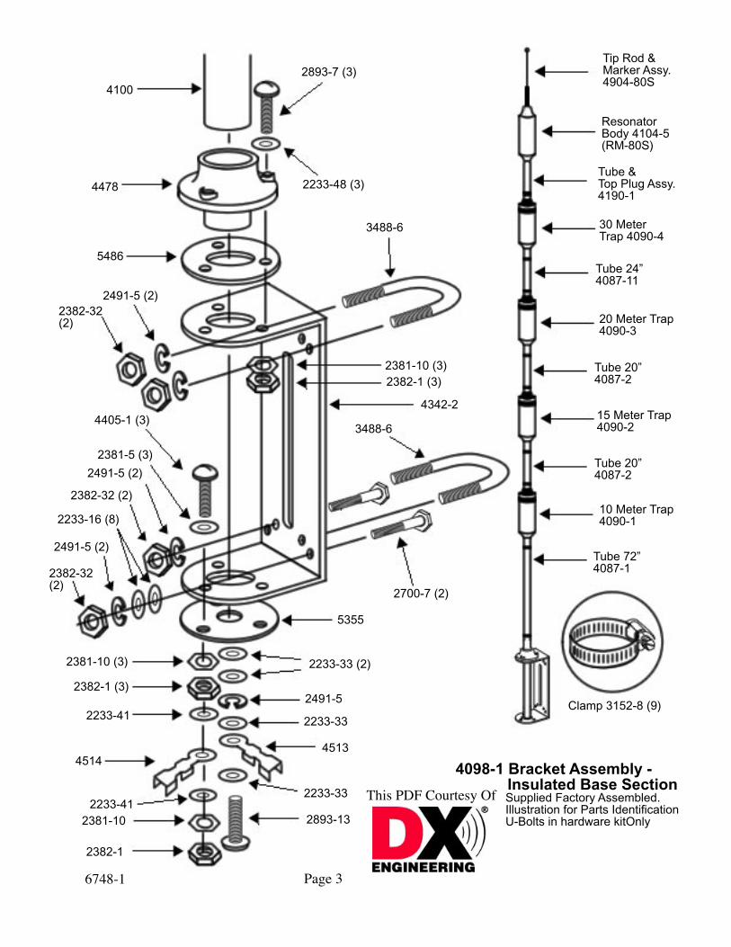
PACKAGE CONTENTSPart Number Description Qty.4087-1 Tube 1-1/4 in. x 72 in. 14087-2 Tube 1-1/4 in. x 20 in. 24087-11 Tube 1-1/4 in. x 24 in 14090-1 10 Meter Trap Assembly 14090-2 15 Meter Trap Assembly 14090-3 20 Meter Trap Assembly 14090-4 30 Meter Trap Assembly 14098-1 Bracket Assembly, Insulated Bas 14104-5 Resonator Body 14190-1 Tube and Top Plug Assembly 14904-80S Tip Rod and Marker Assembly 16747 Hardware Kit 1
IN PLASTIC BAGPart Number Description Qty.2223-41 Washer 1/2 in. O.D. x 3/16 in. I.D. 22382-32 Hex Nut 1/4 in.-20 x 7/32 in. Thick 42491-5 Lock washer 1/4 in. Split 43488-6 U-Bolts 23152-8 Clamps, Tube SS 92382-1 Nut, Hex 10-32 SS 14513 Terminal Lug 1/4 in. Hole 14514 Terminal Lug #10 Hole 16099 Danger Label 12233-16 Washer 5/8 in. O.D. x 1/4 in. I.D. 82382-32 Hex Nut 1/4-20 x 7/32 in. Thick 22491-5 Lock washer _ in. Split 22700-7 Hex Head Bolt 1/4-20 x 1-1/2 in. 22381-10 Lock washer, Ext. #10 SS 1
4100
4478
5486
2491-5 (2)2382-32 (2)
4405-1 (3)
2381-5 (3)
2491-5 (2)
2382-32 (2)
2233-16 (8)
2491-5 (2)
2382-32 (2)
5355
2700-7 (2)
2233-33 (2)
2233-33
4513
2233-33
2893-13
2491-5
2382-1
2381-102233-41
4514
2233-41
2382-1 (3)
2381-10 (3)
Tip Rod & Marker Assy.4904-80S
3488-6
4342-2
2382-1 (3)2381-10 (3)
3488-6
2233-48 (3)
2893-7 (3)
Resonator Body 4104-5(RM-80S)
Tube & Top Plug Assy.4190-1
30 Meter Trap 4090-4
Tube 24” 4087-11
20 Meter Trap 4090-3
15 Meter Trap 4090-2
Tube 20” 4087-2
10 Meter Trap 4090-1
Tube 72” 4087-1
Clamp 3152-8 (9)
Tube 20” 4087-2
4098-1 Bracket Assembly - Insulated Base Section Supplied Factory Assembled. Illustration for Parts Identification U-Bolts in hardware kitOnly
6748-1
This PDF Courtesy Of
Page 3

6748-1
This PDF Courtesy Of
Tip Rod & Marker Assy.4904-80S
15 Meter Trap 4090-2
Recommended Method of Preparing
Split End
Separate strands of braid with an awl,being careful not to break any.
Draw center conductor outwith an awl or dull pointed instrument.
Lug with 3/16”dia. hole onshield end.
Lug with 1/4”dia. hole onhot side.
Solder on the size lugs as indicated above.Tape tightly with plastic electrical tape.
Type of installation
Elevated with radials
Ground mounted without radials
Ground mounted with radials
Approximate dimensions in inches
Dimension Table
A B C D E
2 1/8
0
1
2
1 1/2
1 5/8
1 7/8
1 1/16
1 1/16
1 1/2
2
1 1/2
1
2
1 1/2
Page 4
15 Meter Trap
10 Meter Trap
Resonator Body
30 Meter Trap
20 Meter Trap
FIG 6
6748-1
This PDF Courtesy Of
Page 5
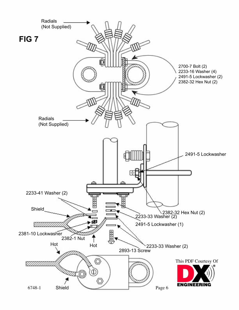
2700-7 Bolt (2)2233-16 Washer (4)2491-5 Lockwasher (2)2382-32 Hex Nut (2)
Radials (Not Supplied)
Radials (Not Supplied)
2233-41 Washer (2)
Shield
2381-10 Lockwasher2382-1 Nut
HotHot
2491-5 Lockwasher
2382-32 Hex Nut (2)2233-33 Washer (2)
2491-5 Lockwasher (1)
2233-33 Washer (2)2893-13 Screw
Shield
FIG 7
6748-1
This PDF Courtesy Of
Page 6

6748-1
This PDF Courtesy Of
4” For InsertionIn Tube Section
Tip Rod Length
The above dimensions are exposed lengths of tip rod.
TIP ROD LENGTHS FOR 75 OR 80 METER RESONATORS USED WITH 6-BTV
Tip rod length measured from top of tip ball down to top of clutchlocking nut as illustrated.NOTE: All resonators are supplied with top rod lengths formobile operation. With the 6-BTV, a shorter length is required,therefore, remove the tip rod from the resonator and grind off thenecessary amount from the end that inserts in the resonator.Before cutting, ascertain the approximate rod length from thechart plus four inches for insertion in the upper tube sectionof the resonator.
Dimensions indicated are approximate.
FREQUENCY (KHz) RM-75S RM-75 RM-80S RM-80
4000 18 in. 21-1/4 in.3950 19-5/8 in. 22 in.3900 21 in. 22-1/2 in.3850 22-1/2 in. 23-3/4 in.3800 24-1/8 in. 24-3/4 in.3750 25-5/8 in. 26 in.3725 26-1/2 in. 26-3/4 in.3700 27-1/4 in. 27-3/4 in.3650 29 in. 29-1/4 in.3600 30-5/8 in. 31 in.3550 33 in. 33 in.3500 34-5/8 in. 34-3/4 in.
Page 7
FIG 8

6748-1
This PDF Courtesy Of
Tip Rod Length
INSTALLATIONThere are two mounting choices.
1. Ground MountIn most areas with normal soil moisture, the 6-BTV can be ground mounted.To ground mount your antenna, use a 4 foot metal pipe or mast of 1-1/4 in. O.D.Drive it into the ground, leaving 18 in. protruding. Do not use concrete. Do notdig a hole and bury the mast. It must be driven in.Follow assembly steps 1-6 before mounting the bracket on the mast. The bracketassembly should be placed on the mast so that the feed-point is 4 in. above theground.After tuning the antenna, compare your A, B, C, D, and E dimensions to the initialdimensions used to assemble the antenna. If your actual dimensions (after tuning)are shorter than the initial dimensions, your ground plane is better than average.If, on the other hand, your actual dimensions are longer, your ground plane ispoorer. If this is the case, radials are suggested.
2. Elevated MountRadials are necessary on elevated installations. The ideal droop angle is 45degrees. A droop angle of 10 degrees to 60 degrees is acceptable. Plan the heightof the mount to allow the best droop angle. Consult page 9 for radial information.When installing resonant radials avoid running them parallel (within 5 feet) to largemasses of metal such as gutters, flashing or metal buildings, etc.The 6-BTV can be mounted on a tower, a heavy duty chimney strap, wooden ormetal pole, or other suitable support structure.CAUTION: Mounting the 6-BTV on towers, tripods, or large mast pipes that areapproximately one quarter wavelength, can often provide an upset to the tuning ofthe radial system, and act as a lossy vertical dipole instead ofthe desired ground plane. To correct this problem, the radial system must be RFisolated from the mounting structure. This may be done by using a nonconductivemounting mast, such as heavy wall fiberglass tube or fiberglass rod orby sliding a split piece of PVC pipe over the metal mast. The coax or mountingbracket should not be directly grounded.6748-1 Page 8In either mount configuration the 6-BTV must be guyed. Attach the guys above the20 meter trap.
Page 8

Normal Configuration Normal Configuration
RADIALS
Radials should be made from insulated wire of #14 gauge or larger. Insulate the ends of elevatedradials. A minimum of two radials per band is required.For Superior performance in all installations, sixteen or more normally spaced radials may rangein length from 14 to 40 feet to fill available space.
RADIAL LENGTHS ARE AS FOLLOWS10 Meters 8 ̓4”15 Meters 11 ̓4”20 Meters 16 ̓4”40 Meters 32 ̓4”75/80 Meters 64 ̓4”
Limited Space Configurations
6748-1
This PDF Courtesy Of
Page 9

6748-1
This PDF Courtesy Of
TUNING FOR ALL CHOICES:
The dimensions given in the Table are approximate and will vary, depending onenvironment. To check antenna tuning, use a sensitive SWR bridge. (DO NOT USE AFIELD STRENGTH METER.) Using only sufficient power to obtain a full scale reading,check and record the SWR at the high, center and low edge of the bands. If the SWRreading is lowest at the high end, lengthen the related section of the antenna; if it islowest at the low end, shorten this antenna section. Always attempt to get the very lowestSWR reading in the center of the band. Tuning in this manner will permit operation inboth the phone and CW portions with a low SWR. If you favor one end of the band or theother, you can retune the antenna to provide the lowest SWR in that portion, if desired.In the process of tuning the antenna, it is mandatory that you always start with 10 metersand work your way up the antenna. Tune 10 first, then 15, 20, 30, 40 and 75/80 meterslast. Any adjustment made on 10 will affect the other bands. Any adjustment made on 15will affect 20, 30 and 40. By the same token, any adjustment on 20 will affect 30 and 40.Adjustment of the individual bands is as follows: 10 meters, adjust Dimension A; 15meters, adjust Dimension B; 20 meters, adjust Dimension C; 30 meters, adjust DimensionD and 40 meters, adjust Dimension E.It is not necessary to remove the bracket each time to adjust the antenna. It is onlynecessary to remove the antenna from the bracket. (If the desired SWR cannot beachieved, it is probably because of an insufficient radial system or poor soilconditions.)Follow the same tuning procedure for 75/80 meters, adjusting the tip rod of the resonatorby loosening the set screws and moving the tip rod (whip). The sleeve on the tip rod can be moved tomark the correct tuning position.
New-Tronics Antenna Corp.One Newtronics Place
Mineral Wells, TX 76067-9563940-325-1386
Page 10

6748-1
This PDF Courtesy Of
GENERAL HINTS
If you are unable to achieve a low VSWR:
Be certain the antenna is not within 15 feet of metallic objects or 10 feet of non-metallicobjects.
The decoupling coil on page 12 should be used. This is especially recommended if TVI ispresent.
If your antenna is elevated, with radials, be certain the mounting bracket is insulated fromthe mounting mast. The RF ground created by the radial system should not be electricallyconnected to earth or DC, ground. The ends of elevated radials should be insulated.
Be certain the radials donʼt run parallel to large metallic objects such asfences. Also avoid metallic objects near the ends of the radials.
Do not use ground rods or ground stakes. They may detune the antenna.
Never bunch radials together. They must be evenly spaced around 360 degrees.
Do not attempt to tune the antenna by changing coax length. Changing coax length maymake the VSWR appear better, but will not change the antenna or its performance.
Antenna tuners are not recommended. Use of a tuner treats the symptom (poor VSWR)but does not correct the problem of a poorly tuned antenna. The antenna must be tunedproperly to radiate efficiently.
Ground mounted antennas should be on a 4 ft. mast only. Masts of other lengths mayresonant at an amateur frequency or a multiple thereof, detuning the antenna.
SPECIAL APPLICATIONS
The 6-BTV can be mounted on metal buildings, RVʼs or other structures, utilizing themetal for a ground plane. The feed point of the antenna should be 4” above the metalground plane. Use the ground mount dimensions for the initial setup.
The 6-BTV is designed for the average ground plane. As the ground plane increases, theantenna becomes shorter. For this reason it may be necessary to trim some sections inorder to reach resonance.
Since your coax shield is connected to where a radial would connect, it too will act as aradial. This is not desirable since this imposes additional currents which will detract fromthe antennas low V.S.W.R. at the rig end of your coax.
Page 11

6748-1
This PDF Courtesy Of
To prevent this from occurring, form at the bottom of the antenna or within eight feet ofthe base, a coil in your coax. By wrapping your coax in a single layer fashion, ten timesaround a 6” diameter form, you will form an R.F. choke in the braid which will isolatethese additional currents from your coax.
Since your coax (the shield) is in the R.F. near field of your antenna, it will act as acollector of R.F. energy (an antenna). This too is not desirable since this can imposesimilar additional currents which will register as a higher V.S.W.R. at the rig.
To prevent this, form the same type coil as before at/or within eight feet of your rig.
These coils will NOT impede the R.F. energy contained inside the coax from flowing. Itonly acts as high impedance to the undesirable additional currents on the outside braid ofyour coax.
After having installed these coils, you may need to retune the antenna.If you still have a high V.S.W.R., perhaps tuned radials are needed.
Any length 50 OHM Cable
Not toexceed
8”
10 Turns6” Dia.
10 Turns6” Dia.
Not toExceed
8”
Page 12
6748-1
This PDF Courtesy Of
New-Tronics Antenna Corp.One Newtronics Place
Mineral Wells, TX 76067-9563940-325-1386
NEWTRONICS ANTENNA CORP.
Newtronics Antenna Corp. warrants its products to be free of defects in material andworkmanship and extends this warranty under intended use and normal serviceconditions to the original owner for a period of one year from the date of purchase.This warranty does not apply to any product that has been repaired or altered in anymanner and is void for any damage due to accident, neglect, unreasonable use, improperinstallation of any other cause not arising out of defects in material of workmanship.The obligations of Newtronics Antenna Corp. are limited to repairing or replacing, at itsoption, any product or part that is returned to the factory, all transportation chargesprepaid, accompanied by proof of purchase and which examination reveals to have beendefective within the warranty period stated above. Newtronics Antenna Corp. does notassume nor is any person authorized to assume for it, any obligations other than thatherein stated. Any implied warranties, including but not limited to fitness for a particularpurpose, are limited in duration for the above one year period. Newtronics Antenna Corp.shall not be liable under this warranty, or any implied warranty, for loss of use of theproduct or for other consequential loss or damage incurred by the purchaser.Some states do not allow the exclusion of limitation of implied warranties ofconsequential damages and so the above exclusions of limitations may not apply. Thiswarranty gives you special legal rights and you may have other rights that vary from stateto state.
Page 13