Installation Instructions FXD Models · PDF fileHarley Davidson FXD Renegade– September...
36
Harley Davidson FXD Renegade– September 13, 2005 Carrier/Pulley Section Updated January, 2008 Lehman Trikes, Inc. Instruction Part # LI6100 Installation Instructions FXD Models Renegade LI6100 September 13, 2005 Updates located in Section P Carrier/Pulley Section Updated January, 2008
-
Upload
trinhkhanh -
Category
Documents
-
view
218 -
download
0
Transcript of Installation Instructions FXD Models · PDF fileHarley Davidson FXD Renegade– September...

Harley Davidson FXD Renegade– September 13, 2005 Carrier/Pulley Section Updated January, 2008
Lehman Trikes, Inc. Instruction Part # LI6100
Installation Instructions FXD Models
Renegade
LI6100
September 13, 2005 Updates located in Section P Carrier/Pulley Section Updated January, 2008

INSTRUCTION PART #LI6100 -11/2008
Please be advised that the standard Lehman Renegade conversion for certain year and model Harley-Davidson motorcycles will not accommodate the original 1 ½” final drive belt. The following applications will require the following drive belt replacement to properly complete the Renegade installation:
Model Belt Required HD Part Number FXD 1999 1-1/8” width, 133 tooth 40015-00
If dealers attempt to install the conversion using the original 1 ½” wide belt, it is possible that it will run partially off the rear pulley, which will either interfere with assembly and/or cause premature belt wear and/or failure. Please advise your customers that they will be charged an additional expense for the necessary drive belt replacement on these older year/model motorcycles upon conversion.
2

Harley Davidson FXD Renegade– September 13, 2005 Carrier/Pulley Section Updated January, 2008
Lehman Trikes, Inc. Instruction Part # LI6100
Table of Contents SECTION A. Introduction/General Information
B. Unpacking Your Kit C. Preparing the Motorcycle
D. Neck Race Preload E. Installing Lehman Swingarm
F. Installing the Differential G. Assembling the Carrier/Pulley Assembly in the Differential H. Belt Tensioning and Tracking
I. Installing the Belt & Differential Guard
J. Attaching, Adjusting and Bleeding the Brake System
K. Installing the Lehman Frame, Suspension & Wheels
L. Installing Passenger Foot Pegs
M. Installing the Exhaust N. Fitting the Body
O. Lights and Wiring
P. Replacement Parts
3

Harley Davidson FXD Renegade– September 13, 2005 Carrier/Pulley Section Updated January, 2008
Lehman Trikes, Inc. Instruction Part # LI6100
A. Introduction/General Information Statements in these instructions preceded by the words WARNING, CAUTION, or NOTE and printed in bold face are very important.
** WARNING ** Indicates a strong possibility of severe personal injury or loss of life if
instructions are not followed.
** CAUTION ** Indicates a possibility of personal injury or equipment damage if
instructions are not followed.
** NOTE ** Gives helpful information to make a step or procedure easier or clearer.
Throughout these instructions "Front" or "Forward" refers to the front of the bike. The front of any component is the end which faces toward the front of the bike. The "Left" and "Right hand" sides refer to the position of the parts as viewed by a rider sitting on the seat, facing forward.
** WARNING ** This kit is designed to be installed by a competent technician experienced and trained in the installation of this kit. Improper installation can result in
severe personal injury or loss of life, as well as damage to the machine. Unqualified installers are urged to have the unit installed by a trained
professional.
These instructions do not include information, specifications, or procedures relating to the motorcycle itself. For this information refer to the factory service manual. The information in these instructions is provided to Lehman Trike dealers, and purchasers of Lehman Trike kits. It is proprietary to Lehman Trikes, Inc. and provided solely for the use of kit purchasers or dealers. Any unauthorised duplication or distribution is a violation of international copyright law.
** NOTE ** Compliance with national (DOT-USA, MOT-Canada), State, Provincial, and local vehicle standards is the responsibility of the installer. Installation of
the optional parking brake is necessary to achieve compliance with DOT/MOT.
4

Harley Davidson FXD Renegade– September 13, 2005Carrier/Pulley Section Updated January, 2008
Lehman Trikes, Inc. Instruction Part # LI6100
B. Unpacking Your Kit The crate contains the following: 1. The differential. 2. Wheel kit. 3. Body. 4. Boxed swing arm. 5. Lehman frame.
6. Hardware box (small parts & bolt bags) 7. Shock absorbers. 8. Warranty Book. 9. Owners Manual. 10. Packing/parts list
Check your kit to the parts list and the order when it arrives. If there are any discrepancies, contact Lehman Trikes immediately.
Fig. B-II
5

Harley Davidson FXD Renegade– September 13, 2005Carrier/Pulley Section Updated January, 2008
Lehman Trikes, Inc. Instruction Part # LI6100 2
Fig. B-II
6

Harley Davidson FXD Renegade– September 13, 2005Carrier/Pulley Section Updated January, 2008
Lehman Trikes, Inc. Instruction Part # LI6100
C. Preparing the Motorcycle The following instructions are a guide to preparing your motorcycle to accept the Lehman Trike Conversion Kit. This will assist you in removing the necessary parts to install on your kit. 1. Note your motorcycle year, model and serial number, as well as the Lehman kit
number (stamped on the differential) on the last page of the Owners Manual. 2. Make sure the motorcycle is standing straight up and the handlebars are centered.
Support the motorcycle under the rear of the transmission so it is straight up and down and the handlebars are straight. The front forks or handlebars should be anchored to hold the bike.
**NOTE** Use a small spirit level on the rear wheel or brake disc to stand the bike straight up, any movement of the handlebars will move the bike off level. Locate a reference on the bike frame that is level and check it frequently
during the installation.
3. Remove the seat and disconnect the battery.
** CAUTION ** Always disconnect the negative battery cable first. If the positive cable
should contact a grounded object while the negative cable is installed, the resulting sparks may cause an explosion.
4. Raise the motorcycle so that the rear wheel is off the ground. 5. Remove the side stand and mufflers. 6. Remove all of the heat shields from the exhaust pipes. 7. Remove the rear fender and wiring harness. The signal lights will be used on the
Lehman body. 8. Remove the shocks and rear wheel. Unbolt the drive pulley from the wheel hub. 9. Remove the brake line from the caliper and remove the caliper. Block the line off to
prevent fluid from leaking out. 10. Remove the pivot shaft retaining bolt and remove the swing arm.
7

Harley Davidson FXD Renegade– September 13, 2005Carrier/Pulley Section Updated January, 2008
Lehman Trikes, Inc. Instruction Part # LI6100
D. Neck Race Preload
The steering head should be approximately twice as tight as factory specifications for a trike conversion. Consult the Harley Davidson service manual for the adjustment procedure.
** NOTE ** Do not tighten the bolts past the factory specifications. Only the bearing
adjustment collar should be tightened to past the factory settings.
8

Harley Davidson FXD Renegade– September 13, 2005Carrier/Pulley Section Updated January, 2008
Lehman Trikes, Inc. Instruction Part # LI6100
E. Installing Lehman Swingarm Provided that they are in good working order, all the original components of the Harley Davidson swing arm may be re-used. 1. Remove o-rings, bearing cones, bearing races and left spacer from the left-hand side
of the original Harley Davidson swingarm. 2. Make sure to keep the bearings matched to the cones. 3. Press out the pivot bushing and dust seal from the right hand side. 4. Clean and inspect original components, replace if necessary. 5. Install components into the Lehman swing arm in the same orientation as the original
swingarm.
Fig. E-I
9

Harley Davidson FXD Renegade– September 13, 2005Carrier/Pulley Section Updated January, 2008
Lehman Trikes, Inc. Instruction Part # LI6100
6. Install the Lehman swingarm with the word “TOP” (stamped into the swingarm collar) facing upward.
Fig. E-II
** NOTE ** Refer to the Harley Davidson service manual for swingarm installation
procedures and torque specifications for your model of motorcycle.
7. Be sure the swingarm moves freely up and down.
10

Harley Davidson FXD Renegade– September 13, 2005Carrier/Pulley Section Updated January, 2008
Lehman Trikes, Inc. Instruction Part # LI6100
F. Installing the Differential 1. Use four (4) – 3/8” x 1 ¼ “ socket head bolts, four (4) high collar lock washers and
four (4) flat washers to attach the left adapter plate (LP1038) to the swingarm.
Fig. F-I
2. Install the belt tension adjuster (3/8” x 4” NC bolt) into the adapter plates. The jam
nuts go on the rear of the plate. 3. Remove the eight 3/8” X 1” cap screws that hold the housing together and split the
differential case. 4. Remove the axles. 5. Install two 3/8” x 3” NF bolts with four flat washers, two lock washers and two
common nuts in the top holes of the pinch blocks. Do not tighten.
11

Harley Davidson FXD Renegade– September 13, 2005Carrier/Pulley Section Updated January, 2008
Lehman Trikes, Inc. Instruction Part # LI6100
6. On the left side housing, install two 3/8” x 3 ½” NF bolts with two flat washers through the bottom holes of the pinch blocks from the inside out. Install left side shock mount plate onto the bolts with the plate pointing back and the threaded hole to the top. The plate must be attached on the outside (wheel side) of the pinch block with flat washers, lock washers and common nuts. Do not tighten.
7. Slide the left half of the differential onto the differential housing adapter plate pins through the pinch blocks. Push the housing as far forward as possible.
Fig. F-II
8. Support the center section approximately 6” off the floor. 9. Feed the belt into the cut out slot in the pulley housing.
12

Harley Davidson FXD Renegade– September 13, 2005Carrier/Pulley Section Updated January, 2008
Lehman Trikes, Inc. Instruction Part # LI6100
G. Assembling the Carrier/Pulley Assembly in the Differential 1. Install the carrier assembly into the right hand half of the differential housing. A soft
hammer may be used to drive the carrier into the housing. The carrier must be straight, and the grease fitting points to the right side.
2. Install the belt tension adjuster (3/8” x 4” NC bolt) into the adapter plates. The jam nuts go on the rear of the plate.
3. Install the adapter plate (LP1038) loosely onto the pinch blocks on the right housing side.
4. Using 3/8” x 3 ½” NF bolts and flat washers, assemble the right shock mount plate to the pinch block on the adapter plate pins. The shock mount plate is on the outside of the pinch blocks. Install flat washers, lock washers and common nuts loosely on the bolts.
5. Loosely install the 3/8” x 3” NF bolts and flat washers in the top holes. Install the flat washers, lock washers and common nuts and leave loose.
Fig. G-I
13

Harley Davidson FXD Renegade– September 13, 2005Carrier/Pulley Section Updated January, 2008
Lehman Trikes, Inc. Instruction Part # LI6100
**NOTE** The pulley will be reversed from the original motorcycle orientation. The
polished rim will be toward the right.
6. Install the right half of the differential into the left half, being sure to align the bearing into the bore, the belt goes onto the pulley, and the grease access hole is down.
Fig. G-II
7. Using the eight 3/8” X 1” housing bolts and lock washers, pull the two halves of the
housing together. Tighten the bolts in such a manner that there is equal pressure around the circumferences of the two housing halves when drawing them together. This will avoid misalignment of the carrier assembly.
** NOTE ** If the bearing will not engage far enough to start the eight housing bolts, use four longer bolts to draw the housing together until the regular bolts
can be started.
8. Torque the bolts to 31 ft-lbs.
14

Harley Davidson FXD Renegade– September 13, 2005Carrier/Pulley Section Updated January, 2008
Lehman Trikes, Inc. Instruction Part # LI6100
9. Use two (2) – 3/8” x 1 1/4 “ socket head bolts, two (2) – 3/8” x 1 1/2 “ socket head bolts, four (4) high collar lock washers and four (4) flat washers to attach the right adapter plate (LP1038) and park brake bracket (LB1292) to the swingarm. Torque the bolts to 31 ft-lbs.
Fig. G-III
10. Install the axles and backing plates.
15

Harley Davidson FXD Renegade– September 13, 2005Carrier/Pulley Section Updated January, 2008
Lehman Trikes, Inc. Instruction Part # LI6100
H. Belt Tensioning and Tracking 1. Using the adjusters, push the differential assembly back until the belt has about 3/8”
slack with 10 lbs pressure at the midpoint of the bottom run. 2. Measure between the mount plates on the swing arm and the welded pinch blocks on
the diff to ensure that the distances are equal. 3. Rotate the pulleys forward for at least 3 revolutions of the rear pulley by pulling
backwards on the bottom run of the belt. Pull the belt straight back to get an accurate reading. Check that the belt is running about 0.030” from the flange on the rear pulley. Tap the differential left or right to achieve this reading.
4. Snug up the 8 cap screws that hold the mount plates to the swingarm. Leave the bolts loose enough to adjust the diff.
5. Once tracking is obtained, re-check the belt tension. Raise and lower the differential assembly slowly with a jack while checking the belt tension. When the tightest position is found, apply 10lbs of force at the midpoint of the lower strand of the belt. The correct deflection is 5/16” - 3/8”. A tool is available from Harley Davidson.
6. Correct the tension by adjusting the tensioner bolts the same amount on both sides. If any adjustment is made you must check the belt tracking again
7. Look along the top of the belt to check the belt alignment on the front pulley. There should be about 0.030” clearance between the pulley flange and the belt. If adjustment is required, loosen the cap screws that hold the mount plate to the swingarm, and tap the differential housing with a rubber mallet in the desired direction. Check the rear alignment and belt tension again if adjustment is required.
** NOTE ** If necessary, apply chalk to the edge of the belt to aid in getting the proper clearance between the belt and the pulley flanges. If visible clearance can
not be obtained, be sure the belt is not climbing up the side of the pulley or squeaking as the belt is rotated. This will be enough clearance.
8. After all of the adjustments are made, tighten the adjuster lock nuts. Tighten the left adapter plate bolts first. Then tighten the left hand pinch block in a criss-cross pattern.
9. Tighten the right hand adapter plate bolts and the right hand pinch block bolts in a criss-cross pattern.
10. Go over pinch block bolts at least 3 times to seat the blocks over the pins. Torque the bolts to 25 ft-lbs.
16

Harley Davidson FXD Renegade– September 13, 2005Carrier/Pulley Section Updated January, 2008
Lehman Trikes, Inc. Instruction Part # LI6100
I. Installing the Belt & Differential Guard 1. The rear of the belt guard fits along the side of the diff. housing and can be fastened
by drilling a 7/32” hole and using a thread cutting bolt with a 1/4” fender washer to fasten. Be sure the bolt does not go in and hit the pulley.
2. Fasten the center of the guard to the bottom of the swingarm with a thread cutting bolt and 1/4” fender washer.
Fig. I-I
17

Harley Davidson FXD Renegade– September 13, 2005Carrier/Pulley Section Updated January, 2008
Lehman Trikes, Inc. Instruction Part # LI6100
J. Attaching, Adjusting and Bleeding the Brake System 1. Attach the brass “T” to the mount on the swingarm with a 1/4” x 1 1/4” bolt, 2 – 1/4”
flat washers and a 1/4” lock nut. 2. Install one end of the brake lines to the wheel cylinders. 3. Route the brake line up the arm of the swingarm to the rear gusset. Secure with
cable ties supplied in kit. Fig. J-I
4. Attach the factory brake line to the brass “T”, fill system, bleed and check for leaks. 5. Install the brake drums and adjust the rear brakes. The brakes are adjusted
manually through the slot in the inside lower portion of the backing plate. Secure the drum to the axle with some washers and a lug nut or two. Set the brakes up so there is a definite drag but the drums will still turn.
6. Fill and bleed the rear brake system with the bleed screws at the wheel cylinders. Check for leaks at all connections.
7. Push the park brake cables through the backing plate and connect the knobbed ends to the levers.
** NOTE ** See Ford drum brake procedures if more detail is needed.
8. Attach the mount as per the diagram supplied (see figure J-lI). 9. Remove the snap ring from one side of the yoke. Hold park brake handle on its side
and push the release button at the end of the park brake handle to allow the yoke pin to slide out.
18

Harley Davidson FXD Renegade– September 13, 2005
Lehman Trikes, Inc. Instruction Part # LI6100
** NOTE ** Some powder coating may need to be removed from the cross tab where the
ratcheting arm hooks onto the park brake bracket
10. Place the hand brake within the park brake bracket, ensuring the ratchet is secure on the cross brace. Attach with the yoke pin.
11. Attach the park brake cable bracket to the hand brake using the clevis pin.
12. Route the left-hand cable sheath across the differential, down and under the right axle from the rear, to the left hole in the handle mount.
13. Route the right hand cable sheath up, around the axle, and forward to the right hole in the handle mount.
14. The cables and lever will move with the differential, so do not route the cables through the frame as chafing will occur during suspension travel.
15. Check for tire clearance. 16. Thread one 5/16” NF
nut onto each brake cable. Place the threaded end of the brake cables through the holes in the cable bracket. Thread a second nut onto each brake cable (see figure L-llI).
17. Ensure the park brakes are properly set up, adjust the parking brake and lock the position.
Fig. J-III
Picture shown is an FLH swingarm. Orientation is the same for FXD models.
Fig. J-II
Picture shown is an FLH swingarm. Orientation is the same for FXD models.
See note to the left
19

Harley Davidson FXD Renegade– September 13, 2005Carrier/Pulley Section Updated January, 2008
Lehman Trikes, Inc. Instruction Part # LI6100
K. Installing the Lehman Frame, Suspension & Wheels 1. 1999 to 2001: Use four (4) 3/8 x 1 3/4” bolts, flat washers (use as many as
needed between the plates and motorcycle frame to align the parts so that nothing is stressed), and lock nuts to attach the frame to the motorcycle. Do no tighten bolts yet.
** NOTE ** Frame spacers and longer mount bolts are supplied with the kit for
2002+ models with the wider rear frame section.
2. 2002+: Use four (4) 3/8 x 2 1/4” bolts, four (4) frame spacers (LS6103), flat washers (as needed) and lock nuts to attach the frame to the motorcycle. Do not tighten bolts yet.
3. The front of the Lehman frame mounts to the welded tab on the motorcycle frame above the swingarm using the stock 5/16” x 9/16” bolt and washer. Apply loctite.
Fig. K-I
20
Harley Davidson FXD Renegade– September 13, 2005Carrier/Pulley Section Updated January, 2008
Lehman Trikes, Inc. Instruction Part # LI6100
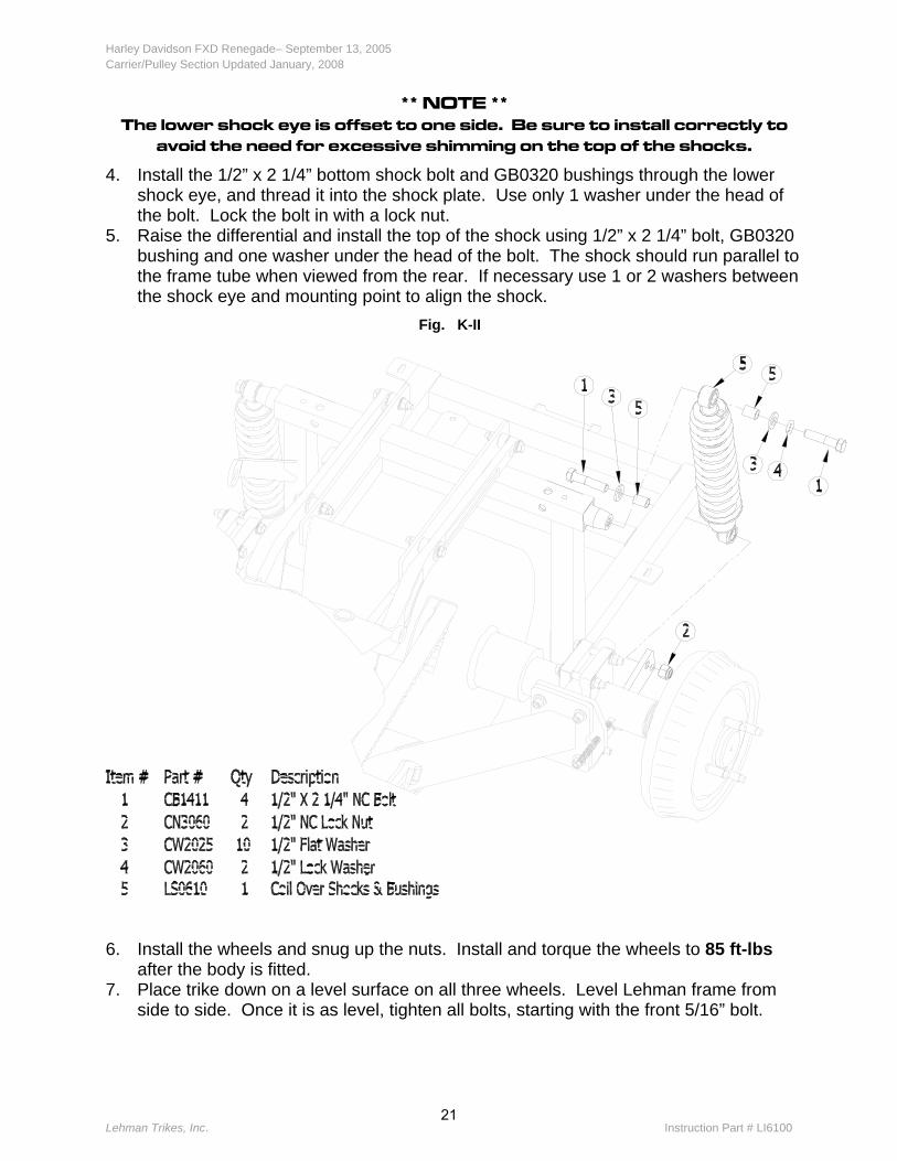
** NOTE ** The lower shock eye is offset to one side. Be sure to install correctly to
avoid the need for excessive shimming on the top of the shocks.
4. Install the 1/2” x 2 1/4” bottom shock bolt and GB0320 bushings through the lower shock eye, and thread it into the shock plate. Use only 1 washer under the head of the bolt. Lock the bolt in with a lock nut.
5. Raise the differential and install the top of the shock using 1/2” x 2 1/4” bolt, GB0320 bushing and one washer under the head of the bolt. The shock should run parallel to the frame tube when viewed from the rear. If necessary use 1 or 2 washers between the shock eye and mounting point to align the shock.
Fig. K-II
6. Install the wheels and snug up the nuts. Install and torque the wheels to 85 ft-lbs after the body is fitted.
7. Place trike down on a level surface on all three wheels. Level Lehman frame from side to side. Once it is as level, tighten all bolts, starting with the front 5/16” bolt.
21

Harley Davidson FXD Renegade– September 13, 2005Carrier/Pulley Section Updated January, 2008
Lehman Trikes, Inc. Instruction Part # LI6100
8. Install the stabilizer bracket LB6101 into the tab on the right side of the Lehman frame. Use a 3/8” NC nylock nut, washers and grommet GG6100 to attach the sway bar to the frame. Leave loose.
Fig. K-III
9. Attach the left-hand side of the sway bar to the sway bar bracket LB6103 using a 3/8”
NC nylock nut, 2 washers and 2 grommets GG6100. Leave loose.
22

Harley Davidson FXD Renegade– September 13, 2005Carrier/Pulley Section Updated January, 2008
Lehman Trikes, Inc. Instruction Part # LI6100
Fig. K-IV
10. The sway bar bracket will attach to the top center diff bolt and the next one to the
rear of it.
23

Harley Davidson FXD Renegade– September 13, 2005Carrier/Pulley Section Updated January, 2008
Lehman Trikes, Inc. Instruction Part # LI6100
Fig. K-V
11. Tighten the 3/8” nuts until there is no free play in the grommets. DO NOT COMPRESS THE GROMMETS.
** CAUTION ** Make sure the sway bar is not pulling or pushing on the Lehman frame
when the trike at rest, for this could alter power train alignment. Make sure the shocks are running vertical after the sway bar is tightened.
There are six (6) 3/8” flat washers supplied to shim the grommets on the sway bar if needed.
24

Harley Davidson FXD Renegade– September 13, 2005Carrier/Pulley Section Updated January, 2008
Lehman Trikes, Inc. Instruction Part # LI6100
L. Installing Passenger Foot Pegs 1. Install the right hand passenger foot peg mount upside down from original position.
The foot peg mount should be up and forward from original position. 2. Remove foot peg from the mount and flip it 180º so it will flip up instead of down.
Fig. L-I
1999 – 2001 Left Hand Passenger Foot peg mounting: 3. Install bracket LR6100 to relocate the left foot peg up and forward of original position.
The short straight part of the bracket bolts to the outside of the motorcycle frame with the longer bent section facing up and forward.
4. Use two (2) 3/8” x 1” bolts and lock washers to attach the relocator to the motorcycle frame.
5. Attach the original foot peg and mount to the relocator using original hardware.
25

Harley Davidson FXD Renegade– September 13, 2005Carrier/Pulley Section Updated January, 2008
Lehman Trikes, Inc. Instruction Part # LI6100
2002+ Left Hand Passenger Foot peg mounting: 6. Remove the original foot peg and mount from the motorcycle. 7. Attach relocator bracket LR6101 to the motorcycle using one (1) 3/8” x 1 1/4” bolt
and lock washer. The relocator will face up and forward of original position. 8. Attach the foot peg to the relocator bracket using original hardware. Foot peg will flip
up when installed correctly.
Fig. L-II
26

Harley Davidson FXD Renegade– September 13, 2005Carrier/Pulley Section Updated January, 2008
Carrier/Pulley Section Updated January, 2008
Lehman Trikes, Inc. Instruction Part # LI6100 O-1
O. Installing the Exhaust 1. All heat shields should be removed. The mufflers, muffler support and rear bracket
should be disassembled. 2. The stock rear header pipe will need to be cut approx. 3 ½” back from the center of
the cross over tube. After the pipe is cut there will be approx. 3 ½” from the end of the pipe to the cross over.
3. Install exhaust pipes LP6100 and LP6101 onto the stock header pipes. Slide exhaust clamps into position and leave loose. Install mufflers onto the Lehman exhaust pipes with the muffler mounting plates pointing up.
Fig. O-I
27

Harley Davidson FXD Renegade– September 13, 2005Carrier/Pulley Section Updated January, 2008
Carrier/Pulley Section Updated January, 2008
Lehman Trikes, Inc. Instruction Part # LI6100 O-2
4. Position exhaust system with a jack stand, then install LB6104 muffler bracket to the mufflers with two (2) - 5/16” x 3/4” carriage bolts (CB1529) and 5/16” flange nuts. Position the mount so it is pointing towards the front of the motorcycle.
5. Install rubber isolator (GM0300) into the slot on bracket LB6104. Fig. O-II
6. Insert bracket GB1200 into the rubber isolator. Attach GB1200 bracket to the
Lehman frame Using two (2) 5/16” x 1 1/2” bolts, four (4) 5/16” flat washers, exhaust spacers LS6101 and lock nuts.
28

Harley Davidson FXD Renegade– September 13, 2005Carrier/Pulley Section Updated January, 2008
Lehman Trikes, Inc. Instruction Part # LI6100 O-3
Fig. O-III
7. Adjust mufflers and pipes so they run even and parallel to one another. 8. Fasten the exhaust clamps to the joint. Position the clamp so they do not squeeze a
slit open on the sides, and the clamp opening does not line up with the slits in the pipe.
9. Inspect exhaust system for exhaust leaks and install heat shields.
29

Harley Davidson FXD Renegade– September 13, 2005Carrier/Pulley Section Updated January, 2008
Lehman Trikes, Inc. Instruction Part # LI6100
N. Fitting the Body The Lehman body provided with the kit is made to accommodate Dyna trike kits. Some trimming maybe necessary to fit the body to the trike.
**WARNING** To meet DOT and MOT requirements one of the following must be
installed on all Lehman Trikes (stock grab handles, stock grab strap or Lehman supplied grab handles). Product liability will not be available for dealers not installing passenger grab handles. Please contact Lehman
Trikes if you require replacement grab handles.
**NOTE** Make sure to install hinge gaskets FG1003 between the body and the
hinge upon reassembly of the body after paint.
**NOTE** To prevent ceasing of fasteners during assembly, apply lubricant to the
threads.
1. Place the side cover inserts (LI6101) into the motorcycle frame where the original shock studs were mounted. The hex end should be on the inside of the motorcycle frame.
2. For the left-hand side cover bracket remove the fuse cover. Mount the shorter part of the side cover bracket (LB6102) with the lower right hand 1/4” hex head self-tapping bolt. The bracket should be horizontal and towards the rear of the trike.
3. Mount the right hand side cover bracket (LB6102) using the rear 5/16” battery box bolt approx. 2” below the ignition key. The shorter side of the bracket should be mounted to this bolt. The bracket should be horizontal and facing the rear of the trike.
4. Mount the side covers to the side cover inserts (LI6101) using 3/8” x 3/4” button head bolt. Some models use a chrome 3/8” button head bolt, this may be used instead if preferred.
5. With the seat in place hold the side covers in place. Slide the side cover bracket up to the side cover and mark the mounting hole as close to the middle of the slot as possible. Drill mount hole to 1/4”
6. The side covers will attach to the brackets in this order, 1/4” x 1” button head bolt, 1/4” stainless flat washer, rubber washer (CW2096), side cover, rubber washer (CW2096), bracket, 1/4” gr. 8 flat washer, and 1/4” lock nut. The bolt heads will be to showing on the outside of the panel when complete.
** NOTE ** Over tightening the side cover fasteners will cause the fibreglass to
crack.
7. Trim the body cut out to fit over frame and side covers as needed.
30

Harley Davidson FXD Renegade– September 13, 2005Carrier/Pulley Section Updated January, 2008
Lehman Trikes, Inc. Instruction Part # LI6100
8. Position the body on the frame so that the wheel clearance is equal on both sides, and the front of each fender is an equal distance from the front of each tire. Center the tire in the wheel cutout when viewed from the side. Shims are provided to level the body to the frame.
9. From the underside of the body, drill a 1/4” hole in the body through each of the four mounting tabs. Keep the hole centered in the slot of each of the tabs.
10. Fasten the body to the Lehman frame as follows. a. (4) x 1/4” x 1 1/2” NC button head bolts, 1/4” x 1 1/4” fender washes and
(FG1002) foam sealing washers install from inside the trunk. b. (4) x CW2097 rubber body washers between the frame and the bottom of the
trunk c. (4) x 1/4” flat washers and locknuts underneath the frame tab to secure the body
to the frame 11. 12. Re-check body alignment and adjust accordingly. 13. Drill the eight (8) holes marked on the body to 1/4”. Install the grab handles using
eight (8) 1/4” x 1 1/4” socket head bolts, eight (8) 1/4” flat washer and eight (8) 1/4” lock nuts. Trim the body as needed to give at least 3/8” clearance to all obstructions.
14. Install seat to the motorcycle. Mark hole location for seat mounting bolt, then drill and tap to 1/4” – 20 (UNC). Use one (1) 1/4” x 1” button head bolt and one (1) rubber washer (CW2096) between bracket and the body to attach the seat.
15. Remove rear wheels. 16. Install body braces (LB6105) by attaching the slotted side to the hole on top of the
Lehman frame using a 5/16” x 3/4” bolt, 5/16" lock washer and flat washer. Slide bracket up against the trunk, mark and drill a 1/4” hole. Attach brackets to the trunk as follows.
a. (2) x 1/4” x 1 1/2” button head bolts, (2) x flat washers, (2) x foam washers (FG1002) install from inside the trunk.
b. (2) x CW2097 rubber body washers between the body brace bracket and the trunk wall.
c. (2) x 1/4 flat washers and lock nuts to secure the brace to the trunk. d. Tighten the 5/16” bolt into place.
17. Remove the body and side covers to have them painted. 18. Reinstall all painted parts. 19. Install weather seal to the body with the lip facing away from the trunk opening.
31

Harley Davidson FXD Renegade– September 13, 2005Carrier/Pulley Section Updated January, 2008
Lehman Trikes, Inc. Instruction Part # LI6100 P-3
P-1 Door Adjustment Procedures
Fig. P-I
32
brianu
Typewritten Text
Fig. N-1

Harley Davidson FXD Renegade– September 13, 2005Carrier/Pulley Section Updated January, 2008
Lehman Trikes, Inc. Instruction Part # LI6100
33
brianu
Typewritten Text
Fig. N-2

Harley Davidson FXD Renegade– September 13, 2005Carrier/Pulley Section Updated January, 2008
Lehman Trikes, Inc. Instruction Part # LI6100
34
brianu
Typewritten Text
Fig. N-3

Harley Davidson FXD Renegade– September 13, 2005Carrier/Pulley Section Updated January, 2008
Lehman Trikes, Inc. Instruction Part # LI6100
O. Lights and Wiring Signal Light Mounting for FXD, FXDL & FXDWG: 1. Mount the factory signal lights and mounts in a suitable area, usually vertically on the
flat below the taillights. Use the factory bolt to attach to the body.
Signal Light Mounting for FXDX & FXDXT: 2. Mount the factory signal lights and Spacers (LS6104) in a suitable area, usually
vertically on the flat below the taillights. Attach the signal lights with mount bolts LB6106. The factory wires from the turn signal will run through the center of the bolt.
3. Install the license plate light in the upper section of the trunk door using two (2) 6-32 x 3/4” bolts on the outside of the door, two (2) 3/16” rubber washers, two (2) #6 flat washers and two (2) 6-32 cap nuts on the inside of the door.
4. Refer to the factory wiring diagram for the color codes of the wire, as well as the necessary connections. Run all of the wires through the tabs located on each of the inner fender walls. Make sure all lights have a proper ground (-).
5. Cut the factory plug in off of the motorcycle rear fender, leaving enough wire on the plug to make all connections to the tail and signal lights
6. Solder and insulate all of the connections with shrink tube. 7. Plug the system into its receptacle. 8. Connect the battery and test all of the lights. 9. Install the seat, fuel tank, and the wheels. Torque the wheels to 85 ft-lbs. 10. Remove the trike from the safety stands/blocks and test drive. Make necessary
adjustments as required.
** NOTE ** The wiring can be installed on the body before it is permanently installed.
Be sure to make the harness long enough to reach the motorcycle plug-in.
35

Harley Davidson FXD Renegade– September 13, 2005Carrier/Pulley Section Updated January, 2008
Lehman Trikes, Inc. Instruction Part # LI6100
P. Replacement Parts Description Lehman Number Vendor Part Number Vendor Brake Shoes GB1118 474RP Raybestos Left Brake Adjuster Kit GB1110 2592 EIS Right Brake Adjuster Kit GB1112 2593 EIS Brake Spring Kit GB1124 7157 EIS Wheel Cylinders GB1122 EW34958 TRU-TECH 12" brake line GB1132 AS312 Papco 30" brake line GB1135 AS330 Papco 40" brake line GB1136 AS340 Papco Differential Cover Gasket (octagon housing) GG0650 RDS 13073 Fel Pro Differential Cover Gasket (square housing) GG0650-0 RDS 55323 Fel Pro Axle Bearing GB1001 RW207 CCRA BCA Axle Flange Gaskets GG0600 n/a AGS Park Brake Cable GB1114 370100 ABSCO Brake Drum GB1120 857 ITT Axle Stud CS1001 560-186 Papco Brake Shoe Retainer GB1119 D7TZ2028B Ford Pinion Seal GS1056 8181 NA National Axle Seal (25 spline shaft drive) GS1052 3214 National Axle Seal (23 spline shaft drive) GS1050 3199 National Park Brake Handle GB1100-0 30011810 Chevrolet FLH Debris Guard LS1018 300026 Lehman Sportster Debris Guard LS1017 n/a Lehman Debris Guard Bracket LB1181 n/a Lehman Speedi Sleeve - all shaft drive GS1058 99181 National
36