
Installation Instructions for TS Type 4 Joining Kit
12
X Installation Instructions for TS Type 4 Joining Kit Part Numbers: 8106.204/504 8108.204/504 8186.204/504 8188.204/504
Transcript of Installation Instructions for TS Type 4 Joining Kit

X
Installation Instructions forTS Type 4 Joining Kit
Part Numbers:8106.204/5048108.204/5048186.204/504 8188.204/504
Installation Instructions for TS Type 4 Joining KitPart Numbers: 8106.204/504, 8108.204/504, 8186.204/504 and 8188.204/504
2
Joining Kit includes:1 box TS8800.430 Angular Baying Brackets2 boxes TS8800.500 Quick-fit Baying Clamps1 box TS8800.400 Baying Clamps1 box TS8800.410 Baying Clamps1 Sealing Sidewall7 red sealing plugs for frame (1 extra)
Tools Required:HammerFlat-blade screwdriver3/8” Socket wrenchCordless screw gun (recommended)T25 Torx driver or bitT30 Torx driver or bit7 mm socket or 7 mm wrench13 mm socket or 13 mm wrench
1. Unpack enclosures.2. Important: Enclosures must be joined together
on a flat and level surface. Do not try to join the enclosures together while they are on a pallet.
3. Remove one sidewall from each enclosure beingjoined. Remove the sidewall on the side of the enclosure that will be joined together. (See Figure 1,Page 8)
4. On one of the enclosures that will be joined, removethe sidewall hanger brackets located near the top ofthe enclosure. (See Figure 1, Page 8, Diagram C)
5. For the same enclosure, remove the rearwall. For easier access to the interior of both enclosures duringinstallation, remove both rearwalls. (See Figure 2, Page 9)Note:The remaining sidewall hardware still installed inone of the remaining enclosures will be used to installthe sealing sidewall in step 10.
6. For the same enclosure, remove the door. The doorcan be removed by using a flat-head screwdriver to disengage the hinge pins holding the door to the hinge. Simply insert the flat of the screwdriver into thegroove at the end of the hinge pins. Push the pin up ordown until the pin disengages. (See Figure 3, Page 10)
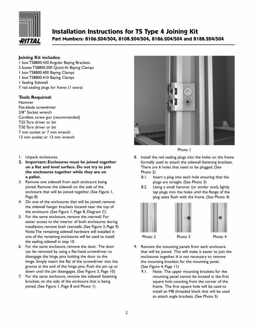
7. For the same enclosure, remove the sidewall fasteningbrackets on the side of the enclosure that is beingjoined. (See Figure 1, Page 8 and Photo 1)
Photo 1
8. Install the red sealing plugs into the holes on the frameformally used to attach the sidewall fastening brackets.There are 6 holes that need to be plugged. (See Photo 2)8.1. Insert a plug into each hole ensuring that the
plugs are straight. (See Photo 3)8.2. Using a small hammer (or similar tool), lightly
tap plugs into the holes until the flange of theplug seats flush with the frame. (See Photo 4)
Photo 2 Photo 3 Photo 4
9. Remove the mounting panels from each enclosure that will be joined. This will make it easier to join theenclosures together. It is not necessary to remove the mounting brackets for the mounting panel.(See Figure 4, Page 11) 9.1. Note: The upper mounting brackets for the
mounting panel cannot be located in the firstsquare hole counting from the corner of theframe. The first square hole will be used toinstall an M8 threaded block that will be used to attach angle brackets. (See Photo 5)

Installation Instructions for TS Type 4 Joining KitPart Numbers: 8106.204/504, 8108.204/504, 8186.204/504 and 8188.204/504
3
Photo 5
10. Using a T25 Torx bit, remove the shipping depth barsfrom the side of the enclosures that are being joinedtogether. These will be reinstalled later.
11. Install the Sealing Sidewall on the enclosure with thesidewall hanging brackets still attached. Position thesidewall over the hangers, center Sealing Sidewall alongthe depth and then allow the Sealing Sidewall to hangvertically. (See Photo 6)
Photo 6
12. Ensure that the centerline of the gasket on the insideof the Sealing Sidewall is aligned with the centerline ofthe frame profile.
13. Securely fasten the Sealing Sidewall to the enclosureusing the sidewall screws removed in Step 3. Onceagain, ensure that the centerline of the gasket on theinside of the Sealing Sidewall is aligned with the center-line of the frame profile.
14. Position the enclosures next to each other and line upthe frame member with the Sealing Sidewall. (SeeFigure 5, Page 12 and Photo 7)14.1. Push the enclosures together as much as
possible to compress the gasket. (See Photo 8)14.2. The inside surface of the frame members should
be approximately parallel to each other.
Photo 7 Photo 8
15. Caution: Do not stand inside either of the enclosuresduring this assembly process. Standing inside the enclosures will not allow the enclosures to pull together evenly.
16. Due to installation methods, tool control, positioningof frames, and slight variations in gasket thickness/width, a minimal amount of gasket tear along the interior joint of the enclosures can be expected andwill not affect the seal.
17. Installation of the TS8800.500 Quick-fit BayingClamps. The TS8800.500 is comprised of a wedge-shaped bracket and four self-tapping T25 Torx screws.Six brackets will be installed on the front and sixbrackets on the rear vertical surfaces of the enclosuresbeing joined together. The clear plastic plugs can be discarded. (See Figure 6, Page 12)17.1. Note: For enclosure heights less than 2000 mm,
the number of brackets that can be installed onthe vertical sections of the frame will be less.To ensure proper installation and spacing, alwaysstart at the top of the enclosure.

Installation Instructions for TS Type 4 Joining KitPart Numbers: 8106.204/504, 8108.204/504, 8186.204/504 and 8188.204/504
4
17.2. Begin at the front of the enclosures where thetwo frames are going to be joined together.
17.3. From the top inside corner of the frame (left or right side), count down 10 round holes (distance between each round hole is 25 mm)on the vertical surface of the frame directlynext to the gasket. This is the mounting hole of the first bracket.
17.4. Insert a screw into the angled slot of the bracket.17.5. Install the screw/bracket into the mounting
hole. Tighten the screw down only halfway.Make sure the bracket is free to move.
17.6. Rotate the bracket until the other angled slot isaligned with the other mounting hole (10 holesfrom the corner).
17.7. Insert a screw into the angled slot of the bracket.17.8. Install a screw into the mounting hole. Tighten
the screw down only halfway. Make sure thebracket is free to move.
17.9. At this point, the bracket should be at an angleto the vertical frame. (See Photo 9)
Photo 9
17.10. Move to the rear of the enclosures.17.11. Repeat steps 17.3 through 17.9 for each corner,
top and bottom.17.12. With a hammer, tap the top of the bracket until
the bracket aligns vertically with the frame. Dothis for both brackets. (See Photo 10 and 11)
Photo 10
Photo 11
17.13. With both brackets in a vertical position, startat the front bracket and tap the top/middle ofthe bracket with a hammer. Tap the bracketdown until the screws are within 1/4" of theend of the slot. This action will start pulling the enclosures together. Do not fully engage thebracket at this time. (See Photo 12 and 13)
Installation Instructions for TS Type 4 Joining KitPart Numbers: 8106.204/504, 8108.204/504, 8186.204/504 and 8188.204/504
5
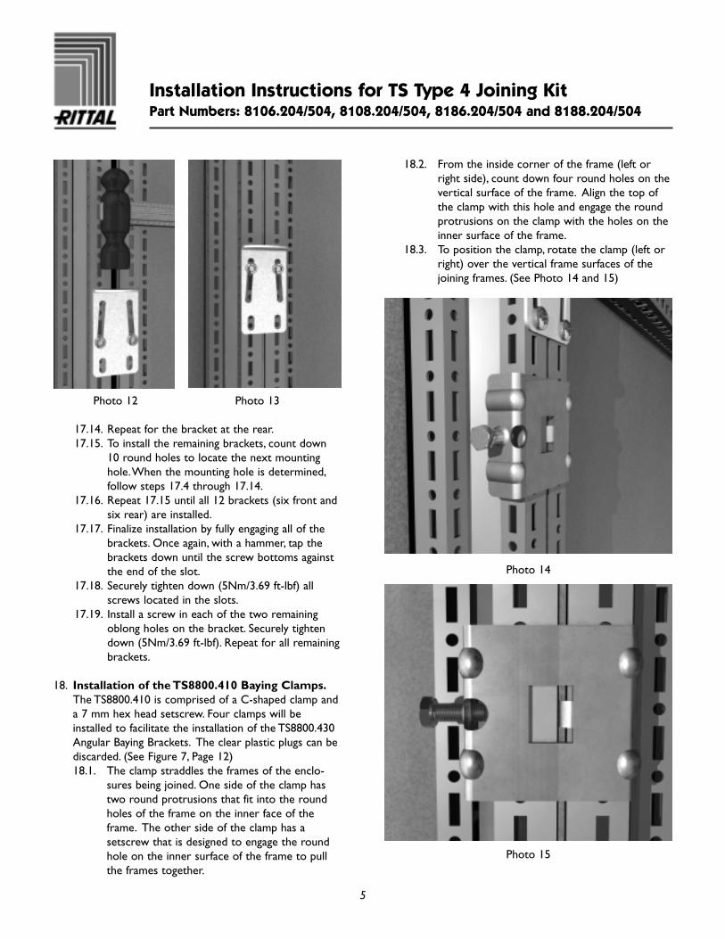
Photo 12 Photo 13
17.14. Repeat for the bracket at the rear.17.15. To install the remaining brackets, count down
10 round holes to locate the next mountinghole.When the mounting hole is determined,follow steps 17.4 through 17.14.
17.16. Repeat 17.15 until all 12 brackets (six front andsix rear) are installed.
17.17. Finalize installation by fully engaging all of thebrackets. Once again, with a hammer, tap thebrackets down until the screw bottoms againstthe end of the slot.
17.18. Securely tighten down (5Nm/3.69 ft-lbf) allscrews located in the slots.
17.19. Install a screw in each of the two remainingoblong holes on the bracket. Securely tightendown (5Nm/3.69 ft-lbf). Repeat for all remainingbrackets.
18. Installation of the TS8800.410 Baying Clamps.The TS8800.410 is comprised of a C-shaped clamp anda 7 mm hex head setscrew. Four clamps will beinstalled to facilitate the installation of the TS8800.430Angular Baying Brackets. The clear plastic plugs can be discarded. (See Figure 7, Page 12) 18.1. The clamp straddles the frames of the enclo-
sures being joined. One side of the clamp hastwo round protrusions that fit into the roundholes of the frame on the inner face of theframe. The other side of the clamp has asetscrew that is designed to engage the roundhole on the inner surface of the frame to pullthe frames together.
18.2. From the inside corner of the frame (left orright side), count down four round holes on thevertical surface of the frame. Align the top ofthe clamp with this hole and engage the roundprotrusions on the clamp with the holes on theinner surface of the frame.
18.3. To position the clamp, rotate the clamp (left orright) over the vertical frame surfaces of thejoining frames. (See Photo 14 and 15)
Photo 14
Photo 15

Installation Instructions for TS Type 4 Joining KitPart Numbers: 8106.204/504, 8108.204/504, 8186.204/504 and 8188.204/504
6
18.4. Slowly tighten the setscrew using a 10 mm hexhead driver or wrench. Ensure that the setscrewis engaging the round hole on the frame; if not,move the clamp until the setscrew is alignedwith the round hole.
18.5. Once the setscrew is engaged, start tighteningthe setscrew until the gap between the enclosures is reduced to ~ 1/8".
18.6. Repeat 18.2 through 18.5 for the three remain-ing clamps.
19. Installation of the TS8800.430 Angular BayingBrackets. The TS8800.430 is comprised of a anglebracket, six self-tapping T25 Torx screws, two M8 x 16 mm hex head bolts, and two M8 threaded blocks.Four brackets will be installed, one on each inside cornerof the enclosures being joined together. The clear plastic plugs can be discarded. (See Figure 8, Page 12)19.1. From the inside corner of the frame (left or
right side), count (up or down) three roundholes on the vertical surface of the framedirectly next to the gasket. This is the mountinghole of the angle bracket.
19.2. Insert a screw into the angled slot of the angle bracket.
19.3. Install the screw/bracket into the mountinghole. Tighten the screw down only halfway.Make sure the bracket is free to move.
19.4. Move the angle bracket until the other angledslot is aligned with the other mounting hole(third from corner). If the hole does not line-up,pull the frames together further by tighteningthe setscrew on the TS8800.410 clamps. (SeePhoto 16)
Photo 16
19.5. Insert a screw into the mounting hole throughthe angled slot of the bracket. Tighten thescrew down only halfway. Make sure the bracketis free to move.
19.6. Do not install the remaining hardware.19.7. Repeat 19.1 through 19.5 for the three remain-
ing angle brackets, one in each corner.
20. Installation of TS8800.400 Baying Clamps. TheTS8800.400 is comprised of a solid metal clamp, a M8 hex head bolt, and an M8 washer. Four clamps willbe installed: two on the top horizontal frame surfaces;and two on the bottom horizontal frame surfaces. (SeeFigure 9, Page 12)20.1. Starting at the top or bottom frames count in
seven square holes along the horizontal fromthe corner of the frames. This is the mountinghole for the clamp. If there is other hardwareoccupying this hole move forward or back tothe next available hole.
20.2. Place the hooked end of the clamp into thesquare with the clamp pointing towards theadjoining enclosure. (See Photo 17)

Installation Instructions for TS Type 4 Joining KitPart Numbers: 8106.204/504, 8108.204/504, 8186.204/504 and 8188.204/504
7
Photo 17
20.3. Rotate the clamp towards the adjoining enclosureframe and insert the end of the clamp into thesquare hole of the adjoining frame. If there issome resistance, use a hammer to tap the clampinto place. Ensure that the tapped hole in theclamp is aligned and accessible through thesquare hole on the inner surface of the frame.
20.4. Insert the M8 bolt and washer into the squarehole in the frame to engage threads. (See Photo 18)
Photo 18
20.5. Slowly tighten the M8 bolt to pull the framestogether until the gap between the enclosures is reduced to ~ 1/8 ". (See Photo 19)
Photo 19
20.6. Repeat 20.1 through 20.5 for the three remain-ing clamps on the horizontal frame members,top and bottom.
21. Finalize installation of TS8800.430 AngularBaying Brackets. (See Figure 8, Page 12)21.1. Note: The upper mounting brackets for the
mounting panel cannot be located in the firstsquare hole counting from the corner of theframe. The first square hole will be used toinstall an M8 threaded block that will be used toattach angle brackets.
21.2. Starting in any of the four corners, with a ham-mer, tap the angle brackets towards the cornerof the frames until the bottom of the bracket isflush against the top or bottom horizontalframe surfaces.
21.3. Insert an M8 threaded block into the firstsquare hole (left or right) from the corner onthe inner surface of the frame.
21.4. Holding the threaded block with your finger,insert an M8 bolt through the large round holein the angle bracket directly above the threadedblock.
21.5. Securely tighten the bolt (9Nm/6.64 ft-lbf).21.6. Repeat 21.3 through 21.5 for the other side of
the angle bracket.

Installation Instructions for TS Type 4 Joining KitPart Numbers: 8106.204/504, 8108.204/504, 8186.204/504 and 8188.204/504
8
Figure 121.7. Repeat 21.2 through 21.6 for the remainingthree corners.
21.8. Install a self-tapping T25 Torx screw in each of the remaining holes on the angle bracket.Securely tighten down (5Nm/3.69 ft-lbf). Repeatfor all remaining brackets.
21.9. Securely tighten down (5Nm/3.69 ft-lbf) allscrews located in the slots of the angle brackets. (See Photo 20)
22. Reinstall the shipping depth bars. If there is hardwareinterference, move the depth bars up or down untilthey can be installed. However, the depth bars must be located as close to the vertical center of the enclosures as possible.
23. The doors, rear walls, and mounting panels can be re-installed at this time.
Photo 20
=
C

Installation Instructions for TS Type 4 Joining KitPart Numbers: 8106.204/504, 8108.204/504, 8186.204/504 and 8188.204/504
9
Figure 2

Installation Instructions for TS Type 4 Joining KitPart Numbers: 8106.204/504, 8108.204/504, 8186.204/504 and 8188.204/504
10
Figure 3
2
1
1

Installation Instructions for TS Type 4 Joining KitPart Numbers: 8106.204/504, 8108.204/504, 8186.204/504 and 8188.204/504
11
Figure 4
1 2 3 4 5 6 7 8 9 10 11 12 13 14 15 16 17 18 19 20 21 22
X

Installation Instructions for TS Type 4 Joining KitPart Numbers: 8106.204/504, 8108.204/504, 8186.204/504 and 8188.204/504
12
Figure 5
Figure 6
Figure 7
Figure 8
Figure 9
Rittal CorporationOne Rittal PlaceSpringfield, OH 45504(937) 399-0500Fax: (937) 390-8392www.rittal-corp.com
IPIP
6
IP