
Installation Instructions for KD, HKD, KDC, CKD, CHKD...
8
I.L. 29C092C Installation Instructions for KD, HKD, KDC, CKD, CHKD Circuit Breakers with Digitrip OPTIM Trip Unit and Powernet and/or Zone Interlock A WARNING CONTACT WITH ENERGIZED EQUIPMENT CAN RESULT IN DEATH, SEVERE PERSONAL INJURY, OR SUBSTANTIAL PROPERTY DAMAGE. DO NOT NANCE ON EQUIPMENT WHILE IT IS ENERGIZED. ALWAYS VERIFY THAT NO VOLTAGE IS PRESENT BEFORE PROCEEDING WITH THE TASK, AND TY PROCEDURES. ATTEMPT TO INSTALL OR PERFORM MAINTE- ALWAYS FOLLOW GENERALLY ACCEPTED SAFE- CUTLER-HAMMER IS NOT LIABLE FOR THE MISAPPLICATION OR MISINSTALLATION OF ITS PRODUCTS. The user is cautioned to observe all recommendations, warnings and cautions relating to the safety of person- nel and equipment as well as all general and local health and safety laws, codes and procedures. Figure 1-1 K-Frame OPTlM Series C Circuit Breaker Frame (OPTIM 550 Shown) The recommendations and information contained herein are based on Cutler-Hammer experience and judgment, but should not be considered to be all-inclusive or cov- ering every application or circumstance which may arise. If any questions arise, contact Cutler-Hammer for further information or instructions. 1-0 INTRODUCTION General Information The K-Frame OPTIM Series C circuit breaker types KD, HKD, and KDC are 600 VAC maximum rated devices with Digitrip OPTIM trip units rated 125A, 250A, or 400A maximum continuous current (Figure 1-1). They are for AC applications only. They are listed in accordance with Underwriters Laboratories, Inc. Standard UL 489 and satisfy the (PI) requirements of International Electrotechnical Commission Recommendations No. IEC 157-1. The OPTIM 750 and 1050 K-Frame circuit breakers are equipped with an extra auxiliary switch and alarm (signal)/lockout switch for customer usage. Other internal accessories are available but must be factory installed. Contact Cutler-Hammer for the follow- ing information and user manuals: K-Frame and Accessories Selection Data 29-120K Instructions and Overview of OPTIM Trip Units 29C890 Instructions on the Operation of Digitrip OPTIMIZER Hand Held Programmer 29C892 Instructions on the Operation of Digitrip Breaker Interface Module 29C893 Instructions on the Operation of Digitrip OPTIM Trip Units 29C891 Digitrip OPTIM Wire Diagrams 29C894 I00 Percent Rated K-Frame Circuit Breakers CKD and CHKD circuit breakers are suitable for contin- uous operation at 100 percent of the frame rating if used with 90°C insulated wire and AL9CU terminals in an enclosure which measures at least 24” high x 15” wide x 6”deep. Ventilation is not required in an enclo- sure having these minimum dimensions. 2-0 INSTALLATION The installation procedure consists of inspecting the cir- cuit breaker and, as applicable, installing the rating plug and terminals; mounting the circuit breaker; connecting Effective October 2002, Supersedes I.L. 29C092B dated February 2001
Transcript of Installation Instructions for KD, HKD, KDC, CKD, CHKD...
I.L. 29C092C
Installation Instructions for KD, HKD, KDC, CKD, CHKD Circuit Breakers with Digitrip OPTIM Trip Unit and Powernet and/or Zone Interlock
A WARNING
CONTACT WITH ENERGIZED EQUIPMENT CAN RESULT IN DEATH, SEVERE PERSONAL INJURY, OR SUBSTANTIAL PROPERTY DAMAGE. DO NOT
NANCE ON EQUIPMENT WHILE IT IS ENERGIZED. ALWAYS VERIFY THAT NO VOLTAGE IS PRESENT BEFORE PROCEEDING WITH THE TASK, AND
TY PROCEDURES.
ATTEMPT TO INSTALL OR PERFORM MAINTE-
ALWAYS FOLLOW GENERALLY ACCEPTED SAFE-
CUTLER-HAMMER IS NOT LIABLE FOR THE MISAPPLICATION OR MISINSTALLATION OF ITS PRODUCTS.
The user is cautioned to observe all recommendations, warnings and cautions relating to the safety of person- nel and equipment as well as all general and local health and safety laws, codes and procedures.
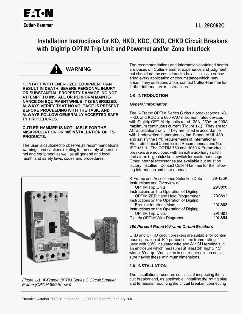
Figure 1-1 K-Frame OPTlM Series C Circuit Breaker Frame (OPTIM 550 Shown)
The recommendations and information contained herein are based on Cutler-Hammer experience and judgment, but should not be considered to be all-inclusive or cov- ering every application or circumstance which may arise. If any questions arise, contact Cutler-Hammer for further information or instructions.
1-0 INTRODUCTION
General Information
The K-Frame OPTIM Series C circuit breaker types KD, HKD, and KDC are 600 VAC maximum rated devices with Digitrip OPTIM trip units rated 125A, 250A, or 400A maximum continuous current (Figure 1-1). They are for AC applications only. They are listed in accordance with Underwriters Laboratories, Inc. Standard UL 489 and satisfy the (PI) requirements of International Electrotechnical Commission Recommendations No. IEC 157-1. The OPTIM 750 and 1050 K-Frame circuit breakers are equipped with an extra auxiliary switch and alarm (signal)/lockout switch for customer usage. Other internal accessories are available but must be factory installed. Contact Cutler-Hammer for the follow- ing information and user manuals:
K-Frame and Accessories Selection Data 29-120K Instructions and Overview of
OPTIM Trip Units 29C890 Instructions on the Operation of Digitrip
OPTIMIZER Hand Held Programmer 29C892 Instructions on the Operation of Digitrip
Breaker Interface Module 29C893 Instructions on the Operation of Digitrip
OPTIM Trip Units 29C891 Digitrip OPTIM Wire Diagrams 29C894
I00 Percent Rated K-Frame Circuit Breakers
CKD and CHKD circuit breakers are suitable for contin- uous operation at 100 percent of the frame rating if used with 90°C insulated wire and AL9CU terminals in an enclosure which measures at least 24” high x 15” wide x 6”deep. Ventilation is not required in an enclo- sure having these minimum dimensions.
2-0 INSTALLATION
The installation procedure consists of inspecting the cir- cuit breaker and, as applicable, installing the rating plug and terminals; mounting the circuit breaker; connecting
Effective October 2002, Supersedes I.L. 29C092B dated February 2001
CASEYLL
I.L. 29C092C
the line and load conductors; torquing terminals; and attaching terminal shields. Circuit breaker frames, rat- ing plugs, accessories, mounting hardware, and unmounted terminals may be supplied in separate pack- ages. To install the circuit breaker, perform the follow- ing steps.
2-1. Compare nameplate data with existing equipment ratings and system requirements to make sure that the circuit breaker is suitable for the intended installation. Prior to mounting, confirm that the circuit breaker has not been damaged during transit or initial handling.
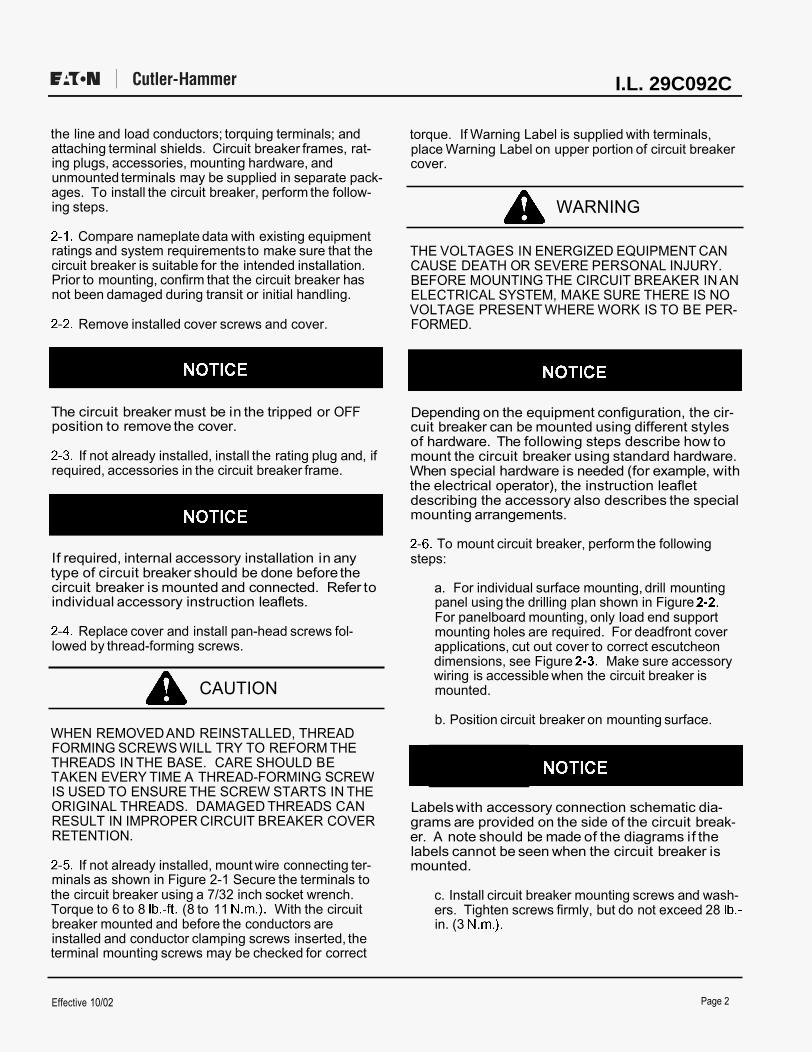
2-2. Remove installed cover screws and cover.
The circuit breaker must be in the tripped or OFF position to remove the cover.
2-3. If not already installed, install the rating plug and, if required, accessories in the circuit breaker frame.
If required, internal accessory installation in any type of circuit breaker should be done before the circuit breaker is mounted and connected. Refer to individual accessory instruction leaflets.
2-4. Replace cover and install pan-head screws fol- lowed by thread-forming screws.
A CAUTION
WHEN REMOVED AND REINSTALLED, THREAD FORMING SCREWS WILL TRY TO REFORM THE THREADS IN THE BASE. CARE SHOULD BE
IS USED TO ENSURE THE SCREW STARTS IN THE ORIGINAL THREADS. DAMAGED THREADS CAN RESULT IN IMPROPER CIRCUIT BREAKER COVER RETENTION.
TAKEN EVERY TIME A THREAD-FORMING SCREW
2-5. If not already installed, mount wire connecting ter- minals as shown in Figure 2-1 Secure the terminals to the circuit breaker using a 7/32 inch socket wrench. Torque to 6 to 8 Ib.-ft. (8 to 11 N.m.). With the circuit breaker mounted and before the conductors are installed and conductor clamping screws inserted, the terminal mounting screws may be checked for correct
torque. If Warning Label is supplied with terminals, place Warning Label on upper portion of circuit breaker cover.
A WARNING
THE VOLTAGES IN ENERGIZED EQUIPMENT CAN CAUSE DEATH OR SEVERE PERSONAL INJURY. BEFORE MOUNTING THE CIRCUIT BREAKER IN AN ELECTRICAL SYSTEM, MAKE SURE THERE IS NO
FORMED. VOLTAGE PRESENT WHERE WORK IS TO BE PER-
Depending on the equipment configuration, the cir- cuit breaker can be mounted using different styles of hardware. The following steps describe how to mount the circuit breaker using standard hardware. When special hardware is needed (for example, with the electrical operator), the instruction leaflet describing the accessory also describes the special mounting arrangements.
2-6. To mount circuit breaker, perform the following steps:
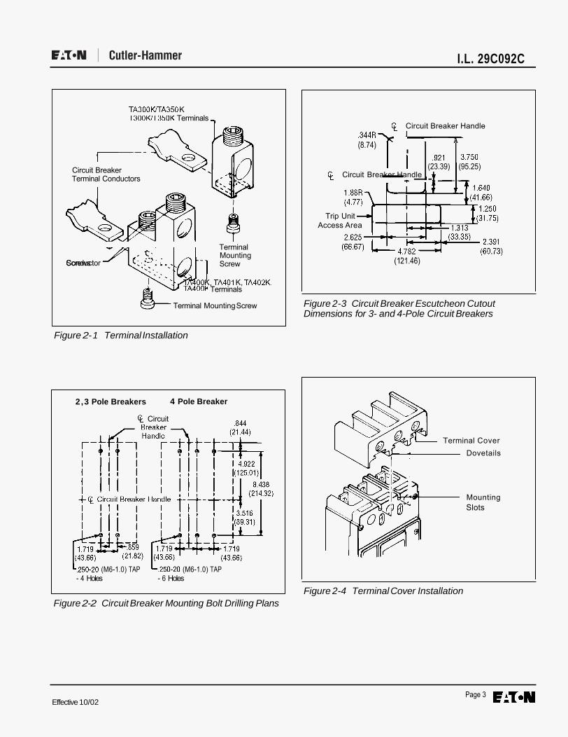
a. For individual surface mounting, drill mounting panel using the drilling plan shown in Figure 2-2. For panelboard mounting, only load end support mounting holes are required. For deadfront cover applications, cut out cover to correct escutcheon dimensions, see Figure 2-3. Make sure accessory wiring is accessible when the circuit breaker is mounted.
b. Position circuit breaker on mounting surface.
e Labels with accessory connection schematic dia- grams are provided on the side of the circuit break- er. A note should be made of the diagrams if the labels cannot be seen when the circuit breaker is mounted.
c. Install circuit breaker mounting screws and wash- ers. Tighten screws firmly, but do not exceed 28 Ib.- in. (3 N.m.).
Effective 10/02 Page 2
I.L. 29C092C
TA300 WTA350 K T300WT350K Terminals ~
Circuit Breaker Terminal Conductors
I
4 Terminal Mounting Screw
TA400K, TA401 K, TA402K,
Conductor Screws . . ..
Terminal Mounting Screw
Figure 2- 1 Terminal Installation
2,3 Pole Breakers 4 Pole Breaker
($ Circuit
L.250-20 (M6-1.0) TAP L.250-20 (M6-1.0) TAP - 4 Holes - 6 Holes
Figure 2-2 Circuit Breaker Mounting Bolt Drilling Plans
$ Circuit Breaker Handle .344R\ I A
,921 3.750 I (23.39) (95.25)
I (8.74)
$ Circuit Breaker Handle - t --
Trip Unit -w Access Area
(1 21.46)
Figure 2-3 Circuit Breaker Escutcheon Cutout Dimensions for 3- and 4-Pole Circuit Breakers
Terminal Cover Dovetails
Mounting Slots
Figure 2-4 Terminal Cover Installation
Effective 10/02 Page 3
Terminals
CASEYLL
I.L. 29C092C
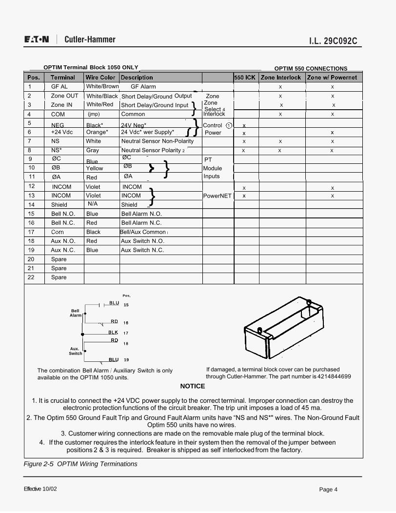
OPTIM Terminal Block 1050 ONLY OPTIM 550 CONNECTIONS
1 I GF AL I GF Alarm i i X i X
2 I Zone OUT I Output I i X i X I I I i i i
3 Zone IN X X
4 COM Common Interlock X X
NEG Black* 24V Neg* Control 0 x 5 6 +24 Vdc Orange* 24 Vdc* wer Supply*7 NS White Neutral Sensor Non-Polarity X X X
8 NS* Gray Neutral Sensor Polarity 2 X X X
Blue
Red
X X
13 INCOM Violet INCOM x X
Yellow Module
14 Shield Shield Bell N.O. Bell N.C.
Aux N.O. Aux N.C.
Blue Bell Alarm N.O. Red Bell Alarm N.C. Black Bell/Aux Common Red Aux Switch N.O. Blue Aux Switch N.C.
20 Spare 21 Spare 22 Spare
15
;; Bell Alarm
Aux. Switch
BLU
The combination Bell Alarm I Auxiliary Switch is only available on the OPTIM 1050 units.
If damaged, a terminal block cover can be purchased through Cutler-Hammer. The part number is 4214844699
NOTICE
1. It is crucial to connect the +24 VDC power supply to the correct terminal. Improper connection can destroy the electronic protection functions of the circuit breaker. The trip unit imposes a load of 45 ma.
2. The Optim 550 Ground Fault Trip and Ground Fault Alarm units have “NS and NS*" wires. The Non-Ground Fault Optim 550 units have no wires.
3. Customer wiring connections are made on the removable male plug of the terminal block. 4. If the customer requires the interlock feature in their system then the removal of the jumper between
positions 2 & 3 is required. Breaker is shipped as self interlocked from the factory.
Figure 2-5 OPTIM Wiring Terminations
Effective 10/02
White/Brown
White/Black
}
19
Pos,
PowerNET}}
Zone
1112
109 ØC ØC
ØB ØB
ØA ØA
INCOM Violet INCOM
Short Delay/Ground White/Red Short Delay/Ground Input
Power x x
ZoneSelect 4
(jmp)
PT
Inputs
N/A
}
Page 4
CASEYLL
CASEYLL
CASEYLL
CASEYLL
CASEYLL
CASEYLL
CASEYLL
Interlock 4
CASEYLL
2
CASEYLL
Polarity
I.L. 29C092C
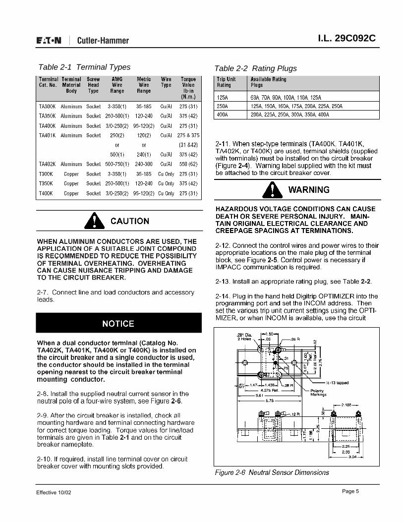
Table 2-1 Terminal Types Table 2-2 Rating Plugs
Effective 10/02 Page 5
CASEYLL
CASEYLL
I.L. 29C092C
1
International
0-off Rating
Plug
Handle Position Indicator Color Red - On
Green -Off (Reset)
Trip ‘Battery and L
Push i Indicator Programming to Trip Trip LEOS Port
Indicator Reset
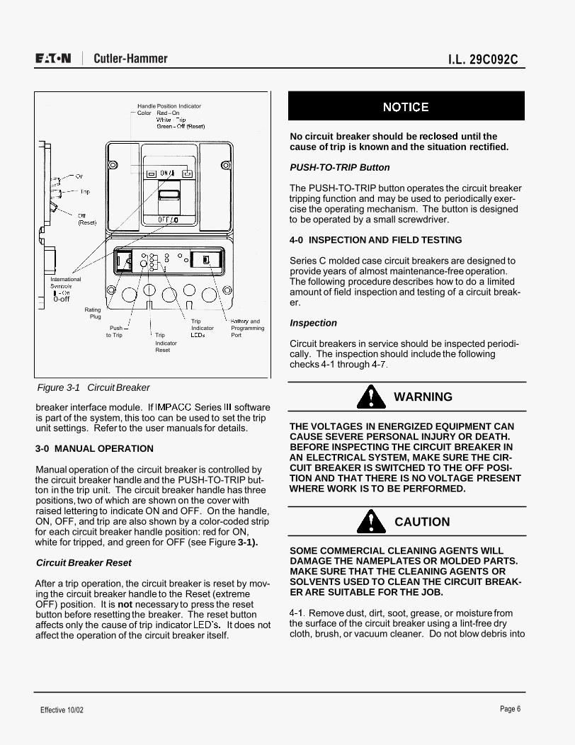
Figure 3-1 Circuit Breaker
breaker interface module. If IMPACC Series Ill software is part of the system, this too can be used to set the trip unit settings. Refer to the user manuals for details.
3-0 MANUAL OPERATION
Manual operation of the circuit breaker is controlled by the circuit breaker handle and the PUSH-TO-TRIP but- ton in the trip unit. The circuit breaker handle has three positions, two of which are shown on the cover with raised lettering to indicate ON and OFF. On the handle, ON, OFF, and trip are also shown by a color-coded strip for each circuit breaker handle position: red for ON, white for tripped, and green for OFF (see Figure 3-1).
Circuit Breaker Reset
After a trip operation, the circuit breaker is reset by mov- ing the circuit breaker handle to the Reset (extreme OFF) position. It is not necessary to press the reset button before resetting the breaker. The reset button affects only the cause of trip indicator LED’S. It does not affect the operation of the circuit breaker itself.
No circuit breaker should be reclosed until the cause of trip is known and the situation rectified.
PUSH-TO-TRIP Button
The PUSH-TO-TRIP button operates the circuit breaker tripping function and may be used to periodically exer- cise the operating mechanism. The button is designed to be operated by a small screwdriver.
4-0 INSPECTION AND FIELD TESTING
Series C molded case circuit breakers are designed to provide years of almost maintenance-free operation. The following procedure describes how to do a limited amount of field inspection and testing of a circuit break- er.
Inspection
Circuit breakers in service should be inspected periodi- cally. The inspection should include the following checks 4-1 through 4-7.
A WARNING
THE VOLTAGES IN ENERGIZED EQUIPMENT CAN CAUSE SEVERE PERSONAL INJURY OR DEATH. BEFORE INSPECTING THE CIRCUIT BREAKER IN AN ELECTRICAL SYSTEM, MAKE SURE THE CIR- CUIT BREAKER IS SWITCHED TO THE OFF POSI- TION AND THAT THERE IS NO VOLTAGE PRESENT WHERE WORK IS TO BE PERFORMED.
A CAUTION
SOME COMMERCIAL CLEANING AGENTS WILL DAMAGE THE NAMEPLATES OR MOLDED PARTS. MAKE SURE THAT THE CLEANING AGENTS OR
ER ARE SUITABLE FOR THE JOB. SOLVENTS USED TO CLEAN THE CIRCUIT BREAK-
4-1. Remove dust, dirt, soot, grease, or moisture from the surface of the circuit breaker using a lint-free dry cloth, brush, or vacuum cleaner. Do not blow debris into
Effective 10/02 Page 6

I.L. 29C092C
circuit breaker. If contamination is found, look for the source and eliminate the problem.
4-2. Switch circuit breaker to ON and OFF several times to be sure that the mechanism linkages operate freely and do not bind. If mechanical linkages do not operate freely, replace circuit breaker.
4-3. With the circuit breaker in the ON position, press the PUSH-TO-TRIP button to mechanically trip the cir- cuit breaker. Trip, reset, and switch circuit breaker ON several times. If mechanism does not reset each time the circuit breaker is tripped, replace the circuit breaker.
4-4. Check base, cover, operating handle, and handle barrier, for cracks, chipping, and discoloration. Circuit breakers should be replaced if cracks or severe discol- oration is found.
4-5. Check wire connecting terminals and other type bus bar connectors for looseness or signs of overheat- ing. Overheating will show as discoloration, melting, or blistering of conductor insulation, or as pitting or melting of conductor surfaces due to arcing. If there is no evi- dence of overheating or looseness, do not disturb or tighten the connections. If there is evidence of over- heating, terminations should be cleaned or replaced. Before re-energizing the circuit breaker, all terminations and cable should be refurbished to the originally installed condition.
4-6. Check circuit breaker mounting hardware, and tight- en if necessary.
4-7. Exposure to certain types of chemicals can cause deterioration of electrical connections. Check area where circuit breaker is installed for any safety hazards, including personal safety and fire hazards and take required precautionary actions.
Field Testing
Any field testing should be done in accordance with applicable NEMA Standard. The operation of circuit breakers with Digitrip OPTIM trip units can be field test- ed periodically using the hand held OPTIMIZER (see user manuals).
Performance Testing for Ground Fault Trip Units
Code Requirements
The National Electrical Code under Article 230-95-C requires that any ground-fault protection system be per- formance tested when first installed. The test shall be conducted in accordance with approved instructions provided with the equipment. A written record of this
test shall be made and shall be available to the authority having inspection jurisdiction.
Standards Requirements
As a follow-up to the basic performance requirements stipulated by the N.E.C. as stated above, UL Standard No. 1053 requires that certain minimum instructions must accompany each ground fault protection system. These following statements plus a copy of the test record form illustrated in Figure 4-1 are shipped with each Digitrip OPTIM trip unit.
General Test Instructions
The interconnected system shall be evaluated in accor- dance with the equipment assembler’s detailed instruc- tions by qualified personnel.
The polarity of the neutral sensor connections (if used) must agree with equipment assembler’s detailed instruc- tions to avoid improper operations following apparently correct simulated test operations. Where a question exists, consult the specifying engineer and/or equipment assembler.
The grounding points of the system shall be verified to determine that ground paths do not exist that would bypass the sensors. The use of high-voltage testers and resistance bridges may be used.
A WARNING
THERE IS A HAZARD OF ELECTRICAL SHOCK OR BURN WHENEVER WORKING IN OR AROUND ELECTRICAL EQUIPMENT. ALWAYS TURN OFF
DUCTING TESTS. POWER SUPPLYING BREAKER BEFORE CON-
NOTICE
Since Digitrip OPTIM trip units derive their operating power from the phase currents, and not from the neutral current, passing current through the neutral sensor only will not properly test the ground fault feature.
Using a low-voltage (0-24 volt), high current, ac source. apply a test current of 125% of the Digitrip OPTIM Ground Fault Trip Unit pick-up setting through one phase of the circuit breaker, as shown in Figure 4-2. This should cause the breaker to trip in less than 1 sec- ond, and if an alarm indicator is supplied, it should oper- ate. Reset the breaker and the alarm indicator. Repeat the test on the other two phases.
If the system is a 4-wire system with a neutral current sensor, apply the same current as described above
Effective 10/02 Page 7

Page 8 I.L. 29C092C
through one phase of the breaker, returning through the neutral sensor, as shown in Figure 4-3. The breaker should not trip, and the alarm indicator, if supplied, should not operate. Repeat the test on the other two phases.
If the system is a 3-wire system with no neutral current sensor, apply the same current as described above through any two phases of the breaker, with the connec- tions exactly as shown in Figure 4-4. The breaker should not trip, and the alarm indicator, if supplied, should not operate. Repeat the test using the other two combinations of breaker phases.
A CAUTION
FIELD TESTING SHOULD BE USED FOR FUNCTION- AL TESTING AND NOT FIELD CALIBRATION OF THE DIGITRIP OPTIM GROUND FAULT TRIP UNIT.
ANY TEMPORARY CONNECTION MADE FOR THE PURPOSE OF CONDUCTING TESTS SHOULD BE RESTORED TO PROPER OPERATING CONDITIONS BEFORE RETURNING THE BREAKER TO SERVICE.
The results of the test are to be recorded on the test form provided with the equipment.
I Low I
Current Limiting Resistor (if required)
Load
Figure 4-2 Connections for Ground Fault Trip Test
GROUND FAULT TEST RECORD FORM Ground Fault Test Records should be Retained by Those in Charge of the Building's Electrical Installation in order to be available to the Authority having Jurisdiction
Test Date Circuit
Breaker Number
Results Tested By
Figure 4-1 Typical Performance Test Record Form
Low Voltage
Current Limiting Resistor (if required)
Load
Figure 4-3 Connections for Ground Fault No-Trip Test, with a Four- Wire System
Low Voltage
Resistor (if required)
Figure 4-4 Connections for Ground Fault No-Trip Test, with a Three- Wire System
Effective 10/02Style 6602C31H04Printed in U.S.A./TQC
Pittsburgh, Pennsylvania U.S.A.


![LEAP@HK “Leading Enterprises Acceleration Programme” · Coaching [HKD 600K] Professional Services [HKD 960K] Business Expansion [HKD 600K] 6 We Create Value Beyond Money through...](https://static.fdocuments.us/doc/165x107/6051af1923a5480ec20c8336/leaphk-aoeleading-enterprises-acceleration-programmea-coaching-hkd-600k-professional.jpg)


