INSTALLATION INSTRUCTIONS for HI-6 CD IGNITION · HI-6 CD IGNITION WITH REV LIMITER AND TIMING...
24
9000-6000C 1 3/99 CAUTION: READ THE FOLLOWING CAREFULLY: • Standard HI-6 units (6000-6420, 6000-6421, 6000-6422, and 6000-6423) are sealed for protection against occasional water drips. However, standard HI-6 units MUST NOT be mounted in areas exposed to water splash or sprayed with water. Moisture forced into the HI-6 unit can cause an internal electrical short circuit. This could destroy the HI-6 unit and VOID YOUR WARRANTY! • If you are mounting a standard HI-6 unit in the engine compartment, direct the cable exit down, so that moisture can drain out. Always cover the HI-6 unit when cleaning the engine compartment. • Severe automotive environments and race applications require the HI-6R (6000-6400), HI-6DSR (6000-6424), or part number 6000-6466 (HI-6R and TRC-2 kit) . Marine applications require the HI-6M (6000-6462). These HI-6 versions are fully encapsulated with urethane and include wire harnesses with Weather Pack connectors. • Make sure that all original equipment wires are disconnected from coil. GM coil-in-cap HEI: Install black ground wire as shown in Figure 5 or 7. • Tape up any unused wires after completing the installation. If the magnetic trigger leads are not used, cut short and tape up each lead separately. If the white points trigger wire is not used, tape it up. If unused trigger leads short together or to ground, the HI-6 will not run. INTRODUCTION The Crane Cams HI-6 is an advanced capacitive dis- charge (CD) type ignition system intended for racing and per- formance street vehicles. The HI-6 is 50 states street legal (California Air Resources Board E.O. D-225-52 and D-225-63 for 1995 and prior non-OBD II vehicles) and can be installed in most vehicles. Trigger sources include: • Electronic ignition module • Magnetic pickup distributor • Crank trigger system • Points distributor INSTALLATION INSTRUCTIONS for HI-6 CD IGNITION WITH REV LIMITER AND TIMING RETARD Part Numbers 6000-6400, 6000-6420, 6000-6421, 6000-6422, 6000-6423, 6000-6424, 6000-6425, 6000-6466 CAUTION: READ INSTRUCTIONS CAREFULLY BEFORE STARTING INSTALLATION. READ THIS BEFORE YOU BEGIN! Before proceeding with the HI-6 installation, read the introduc- tory material below so that you will understand the basic features and operation of the unit. The installa- tion instructions are organized by application; use the Applications Index to find the appropriate sec- tion for your vehicle. For HI-6 Part Number 6000-6466 or hookup of optional TRC-2 Timing Retard Control Part Number 6000- 6425, additional information is pro- vided in the TRC-2 supplement starting on page 21. CAUTION: The HI-6 is not compatible with any odd firing engines or distributorless ignition systems. Use the HI-6DI 2 (part number 6000-6500) for distributorless ignitions. APPLICATIONS INDEX Late Model Computer Controlled Vehicles with Stock Electronic Ignition . . Pg 7 (most 1981 and up vehicles with O.E. electronic ignition and engine control computer, European vehicles with Bosch Hall Effect ignition ) Earlier Electronic Ignition Systems Without Computer Control (Magnetic Triggered Systems) . . . . . . . . Pg 12 (most 1974-1980 vehicles with magnetic pickup distributor and any vehicles with aftermarket crank trigger) Honda and Acura Integra . . . . . . . . . . . . Pg 13 Early Vehicles with Points . . . . . . . . . . . . Pg 13 Vehicles with Aftermarket Ignitions . . . . Pg 16 (includes Crane XR700, XR3000, and Mallory Unilite points conversion.) 530 Fentress Boulevard, Daytona Beach, FL 32114 Tech Line: (386) 258-6174 Fax: (386) 258-6167 Check our web site for updates: www.cranecams.com
Transcript of INSTALLATION INSTRUCTIONS for HI-6 CD IGNITION · HI-6 CD IGNITION WITH REV LIMITER AND TIMING...

9000-6000C13/99
CAUTION: READ THE FOLLOWING CAREFULLY:• Standard HI-6 units (6000-6420, 6000-6421, 6000-6422, and 6000-6423)
are sealed for protection against occasional water drips. However, standardHI-6 units MUST NOT be mounted in areas exposed to water splash orsprayed with water. Moisture forced into the HI-6 unit can cause an internalelectrical short circuit. This could destroy the HI-6 unit and VOID YOURWARRANTY!
• If you are mounting a standard HI-6 unit in the engine compartment, directthe cable exit down, so that moisture can drain out. Always cover the HI-6unit when cleaning the engine compartment.
• Severe automotive environments and race applications require the HI-6R(6000-6400), HI-6DSR (6000-6424), or part number 6000-6466 (HI-6R andTRC-2 kit) . Marine applications require the HI-6M (6000-6462). These HI-6versions are fully encapsulated with urethane and include wire harnesseswith Weather Pack connectors.
• Make sure that all original equipment wires are disconnected from coil.GM coil-in-cap HEI: Install black ground wire as shown in Figure 5 or 7.
• Tape up any unused wires after completing the installation. If the magnetictrigger leads are not used, cut short and tape up each leadseparately. If the white points trigger wire is not used, tape itup. If unused trigger leads short together or to ground, theHI-6 will not run.
INTRODUCTIONThe Crane Cams HI-6 is an advanced capacitive dis-
charge (CD) type ignition system intended for racing and per-formance street vehicles. The HI-6 is 50 states street legal(California Air Resources Board E.O. D-225-52 and D-225-63for 1995 and prior non-OBD II vehicles) and can be installed inmost vehicles. Trigger sources include:
• Electronic ignition module
• Magnetic pickup distributor
• Crank trigger system
• Points distributor
INSTALLATION INSTRUCTIONS for
HI-6 CD IGNITIONWITH REV LIMITER AND TIMING RETARDPart Number s 6000-6400, 6000-6420, 6000-6421, 6000-6422,
6000-6423, 6000-6424, 6000-6425, 6000-6466
CAUTION: READ INSTRUCTIONS CAREFULLY BEFORE STARTING INSTALLATION.
READ THIS BEFOREYOU BEGIN!
Before pr oceeding with theHI-6 installation, read the intr oduc-tor y material belo w so that y ou willunder stand the basic f eatures andoperation of the unit. The installa-tion instructions are or ganiz ed byapplication; use the ApplicationsIndex to find the appr opriate sec-tion f or y our vehic le.
For HI-6 Part Number 6000-6466or hookup of optional TRC-2 TimingRetard Contr ol Part Number 6000-6425, additional inf ormation is pr o-vided in the TRC-2 supplementstar ting on pa ge 21.
CAUTION: The HI-6 is not compatib lewith an y od d firing engines ordistrib utorless ignition systems. Usethe HI-6DI2 (par t number 6000-6500) f ordistrib utorless ignitions.
APPLICATIONS INDEXLate Model Computer ControlledVehicles with Stock Electronic Ignition . . Pg 7(most 1981 and up vehicles with O.E.electronic ignition and engine controlcomputer, European vehicles withBosch Hall Effect ignition )
Earlier Electronic Ignition SystemsWithout Computer Contr ol(Magnetic Triggered Systems) . . . . . . . . Pg 12(most 1974-1980 vehicles with magneticpickup distributor and any vehicles withaftermarket crank trigger)
Honda and Acura Integra . . . . . . . . . . . . Pg 13
Early Vehicles with Points . . . . . . . . . . . . Pg 13
Vehicles with Aftermarket Ignitions . . . . Pg 16(includes Crane XR700, XR3000, andMallory Unilite points conversion.)
530 Fentress Boulevard, Daytona Beach, FL 32114Tech Line : (386) 258-6174 Fax: (386) 258-6167Check our web site for updates: www.cranecams.com

9000-6000C23/99
MULTIPLE SPARK Under low RPM cranking condi-
tions, the HI-6 generates up to 12sparks. This assures quick startingeven under the most adverse condi-tions. At idle and cruise, the numberof sparks fired is adjusted to maintaina total spark duration of approximate-ly 20 degrees (crankshaft), assuringsmooth idle, improved throttleresponse, and eliminating the leansurge characteristic of some latemodel emission controlled vehicles.Above 3,000 RPM, the HI-6 gener-ates a single powerful spark withmany times the spark gap current ofmost competitive systems.
DIGITAL SEQUENTIALREV LIMITER
All HI-6 units have an externallyactivated stage rev limiter that can bedigitally set from 600 to 9,900 RPM in100 RPM increments via rotaryswitches. The yellow/white wire (yel-low with thin white stripe) is used toactivate the stage rev limiter. Sincemost late model vehicles have on-board engine control computers thatset a safe maximum rev limit, thestage limit feature on the HI-6 can beused for selecting a lower rev limit fordrag racing.
The HI-6DS (6000-6423) and HI-6DSR (6000-6424) have a two stagerev limiter. An additional set of rotaryswitches sets the maximum rev limiton the HI-6DS and HI-6DSR from600 to 9,900 RPM in 100 RPM incre-ments.
The stage limit is activated byapplying +12V to the yellow/whitewire. If the stage limit is not activated,the maximum rev limit is selected.
The rev limiter can be set tooperate with 4, 6 or 8 cylinderengines. Accuracy is +/-30 RPM.Therev limiter is not compatible with anyodd firing engines.
The HI-6 utilizes a sequential fir-ing program to equalize cylinder fir-ing at the rev limit. When engine RPMexceeds the rev limit, firing stops.TheHI-6 counts the number of cylinderfirings that are skipped. Once RPMdrops below the rev limit, firing isresumed when the count reaches anodd number. If the engine is heldagainst the rev limit, RPM will staywithin a narrow band. All cylinderswill be fired equally in rotation. Fuelloading and plug fouling will be great-ly reduced. Sequential firing alsominimizes harmonics and vibrationsthat can stress engine and drivetrainparts.
RETARD CAPABILITYAll HI-6 units have a timing retard
capability. Several retard modes aresupported including boost propor-tional retard. An optional TRC-2Timing Retard Control module (6000-6425) is required to make use of thetiming retard capability. Note that HI-6 part number 6000-6466 is sold as akit that includes the TRC-2 unit. TheTRC-2 attaches to the brown/whitewire (brown with thin white stripe).Refer to the TRC-2 supplement start-ing on page 21 for details.
TRIGGER RETARDCOMPENSATION
Magnetic pickups have an inher-ent retard characteristic. The RISCmicrocontroller within the HI-6 auto-matically compensates for this retardcharacteristic and maintains ignitiontiming constant within +/- .5 degreethroughout the entire RPM range.
TACH TEST FEATUREThe HI-6 includes a tach test fea-
ture that can be used to testtachometers and other RPM activat-ed accessories connected to the HI-6 tach output (green wire). The tachtest feature is described in greaterdetail in the tach hookup sectionstarting on page 18.
CYLINDER SELECT (BLUE)
RETARD INPUT (BROWN / WHITE)
STAGE LIMIT INPUT (YELLOW / WHITE)
AB
CD
EF
IGNITION + (THIN RED)POINTS (WHITE) COIL - (BLACK)
COIL + (ORANGE)MAG + (VIOLET)MAG - (GREEN)
TACH (GREEN)
BAT +(HEAVY RED)
GROUND(HEAVY BLACK)
NOTE:Basic HI-6 units do not includeweather pack connectors onwire harness.
MAGNETICTRIGGER
Figure 1. HI-6 Wire Identification
9000-6000C33/99
DIAGNOSTICSWhen the ignition switch is
turned on, the HI-6 completes aninternal diagnostic check and lightsup the status LED. When the engineis cranked, the status LED will rapid-ly blink to indicate that a valid triggersignal is being received.
If certain failure modes occur,the HI-6 will shut off (engine stopsrunning) and the status LED will con-tinuously blink a diagnostic code,similar to a check engine light. TheLED will blink a number of times fol-lowed by a 2 second pause. Thenumber of blinks indicates the faultmode. Refer to the troubleshoootingsection starting on page 18.
COIL COMPATIBILITYMost O.E. (original equipment)
coils are compatible with the HI-6.We recommend the Crane CamsPS91 or LX91 for street performanceand the PS92 or LX92 for profes-sional racing use. The PS92/LX92are capable of continuous operationat 8,500 RPM and 85 degrees C(185 degree F) ambient tempera-ture. A detailed coil compatibilitychart is given on page 24.
SPARK PLUGS ANDWIRES
Do not use solid core wire, asthis can generate electrical noisethat may interfere with the HI-6 orother on-board computer and radioequipment. Do not use high resis-tance carbon wire, as this may burnout from the high energy levels.Optimum wire resistance is 300-800ohms per foot.
For optimum performance inracing applications use only non-resistor spark plugs. Resistor spark
plugs are required for all street appli-cations unless recommended other-wise by vehicle manufacturer.Recommended plug gap is .045" fornormally aspirated engines used foroff-road racing.
MOUNTING THE HI-6 Preferred mounting location for
the HI-6 is within the passengercompartment. If the HI-6 is mountedwithin the engine compartment,make sure that the mounting loca-tion is away from exhaust systemheat, protected from water splash,and has good airflow for cooling.Orient the cable exit downward sothat moisture can drain out.
When you have picked a mount-ing location, make sure that the wireharness will reach and that the revlimit switches are accessible. Usethe sheet metal screws provided inthe parts bag to mount the unit.Rubber shock mounts are recom-mended for racing.
BASIC HOOKUPThis section provides generic
hookup information that can be usedfor applications not specifically refer-enced in the Applications Index.
A parts bag with hardware andelectrical terminals is provided foryour convenience. You will requirecommon hand tools including aproper wire stripping and crimpingtool. Do not attempt to use pliers tocrimp terminals. All connectionsmust be made with stranded copperwire. Crimp terminals are recom-mended over soldering for most
applications. Soldering can makewires brittle near the solder joint.
Make sure all terminals areclean and free of corrosion. Scrapeoff paint, dirt, and grease when mak-ing connections to chassis ground.
POWER AND GROUND Heavy Red Connect to Battery+ orbattery cable at starter solenoid. Use3/8" ring terminal supplied.
Heavy Black Connect to chassisground. Scrape off paint to insuregood contact. Use 3/8" ring terminal.Do not lengthen this wire.
COIL CABLEOrange Connect to Coil+. Removeall other wires from Coil+ terminal.
Black Connect to Coil-. Remove allother wires from Coil- terminal.
IGNITION SWITCHRed Connect to switched +12 volts.Usually this will connect to the O.E.wire that was removed from Coil+. Ifthe O.E. wiring to Coil+ included aballast resistor, the resistor does nothave to be removed.
CYLINDER SELECTBlue Refer to Figure 4:
8 cyl: Do not connect. Tape up wire.
6 cyl: Connect to ground with 1/4"ring terminal.
4 cyl: Connect to red ignition switch wire with 3M splice found in parts bag.
CAUTION: Use only lowresistance spark plugwires such as CraneFireWire.
CAUTION: If theheavy red wire must beextended, use 10 or 12gauge copper wire andread the filter capacitornote on page 20.
CAUTION: Route coilcable away from allother wires, especiallythe trigger inputs.
WARNING: High voltage ispresent at the coil primaryand secondary terminals.Do not touch the coil whilethe engine is running. Donot connect any testequipment to the coil .
Note that some HI-6 ver-sions use a wire harnesswith mating WeatherPack connectors that arenot shown for clarity inthe hookup drawings.

9000-6000C43/99
– +
12 VOLTBATTERY
IGNITIONSWITCH
BALLASTRESISTOR
(not always used)
+12V
RUN
STARTO. E. WIRE THAT WASREMOVED FROM COIL +
O. E.ELECTRONIC
IGNITIONMODULE
CONDENSER
� OR �
TRIGGERSOURCE
BREAKERPOINTS
HI-6WHITEPOINTS
THIN REDIGNITION
HEAVY REDBAT +
O. E. WIRETHAT WAS REMOVED
FROMCOIL �
CUT WIREAND REMOVECONDENSER
IF NECESSARY
SEENOTE 1
COIL
+ �F
F BLACKCOIL �
ORANGECOIL +
COILCABLE
SEENOTE 1
FM
MAGNETIC TRIGGER CABLECUT SHORT AND TAPE UP
HEAVY BLACKCHASSIS GROUND
FM
NOTES:1. Connections to O.E. wire that were
removed from Coil – and Coil + aremade with two sets of 1/4"male -female quick disconnects.
2. Refer to Figure 4 in for tach, cylinderselect and stage limit hookup.
3. O.E. ballast resistor is not required,but can be left connected.
4. Any condenser at points, O.E. module,or coil must be disconnected and removed.
5. Use 3/8" ring terminals for batteryand ground connections.
COIL CONNECTIONSMADE WITH TWO45º MALE TERMINALSAND TWO 1/4" FEMALEQUICK DISCONNECTS
Figure 2. Basic Points or Computer Control Hookup
9000-6000C53/99
– +
12 VOLTBATTERY
IGNITIONSWITCH
BALLASTRESISTOR
(not always used)
+12V
RUN
STARTO. E. WIRE THAT WASREMOVED FROM COIL +
HI-6
WHITEPOINTSTAPE UP
THIN REDIGNITION
HEAVY REDBAT +
COIL
+ �F
F BLACKCOIL �
ORANGECOIL +
COILCABLE
FM
MAGNETICTRIGGER
CABLE
HEAVYBLACK CHASSIS
GROUND
NOTES:
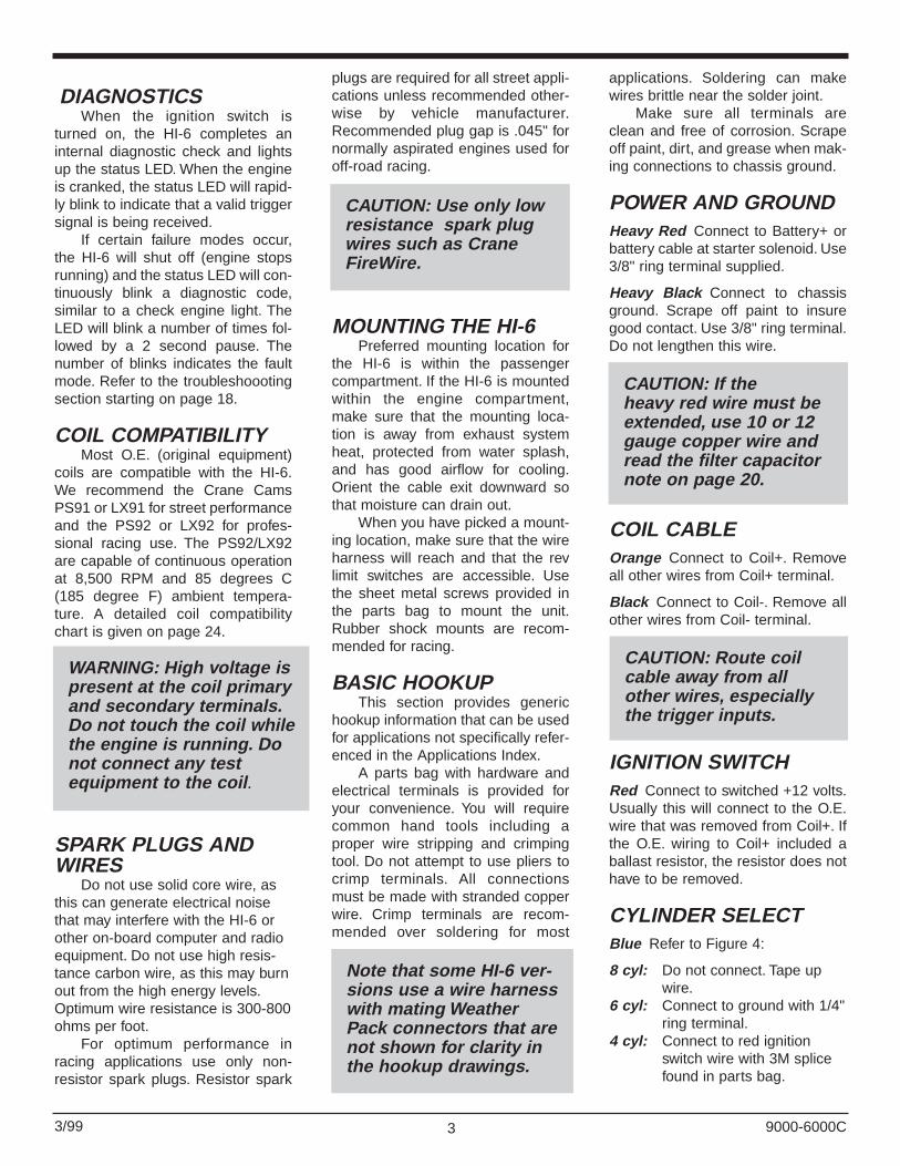
1. Refer to Figure 4 in for tach, cylinderselect and stage limit hookup.
2. O.E. ballast resistor is not required,but can be left connected.
3. Any condenser at coil must bedisconnected and removed.
4. Additional quick disconnects areprovided in parts bag to allow easyreconnection of O.E. wires if HI-6unit is removed.
5. Use 3/8" ring terminals for batteryand ground connections.
COIL CONNECTIONSMADE WITH TWO45º MALE TERMINALSAND TWO 1/4" FEMALEQUICK DISCONNECTS
F M
F M MAGNETICPICKUP DISTRIBUTOR
(FORD COLOR CODES SHOWN)
VIOLETMAG +
GREENMAG -
ORANGE
PURPLE
1/4" MALE-FEMALEQUICK DISCONNECTS
1/4" MALE-FEMALEQUICK DISCONNECTS
3/16" MALE-FEMALEQUICK DISCONNECTS
Figure 3. Basic Magnetic Trigger Hookup

63/99 9000-6000C
STAGE LIMIT INPUT Yellow/White Yellow wire with thinwhite stripe. Refer to Figure 4.Connect to a normally open switchas shown. When the switch isclosed and +12V is applied to theinput, the stage rev limit is active.
For single rev limit HI-6 ver-sions, you can connect the stageinput directly to the thin red ignitionwire with a 3M wire splice to perma-nently activate the rev limit.
RETARD INPUT Brown/White Brown wire with thinwhite stripe. Unless you are con-necting the optional TRC-2 acces-sory (see page 21), tape up thiswire.
TACH OUTPUT Green Refer to Figure 4. Connectto tachometer using 1/4” male andfemale quick disconnects. Connectelectronic fuel injections and RPM
activated systems that require a 12volt tach signal to this wire. Sometachs may require an adapter. Referto the Tach Hookup section on page18 for details.
TRIGGER INPUTSThe magnetic trigger cable is
used for all magnetic pickup distribu-tors and crank trigger systems. Thewhite "points" trigger wire is used fortriggering from ignition modules andpoints. Twisted pair type cable isused for the magnetic trigger cableto prevent electrical noise. Either themagnetic trigger or "points" triggerinput will be used. Do not connectboth. Refer to Figures 2 and 3.
F MRPMX100
TACHOMETER
+12V
INSTALL SUPPLIED SURGEABSORBER IF SOLENOIDVALVE IS USED(REFER TO PAGE 20)
NORMALLY OPENSTAGE LIMIT SWITCH
YELLOW / WHITESTAGE LIMIT
1/4" MALE-FEMALEQUICK DISCONNECTS
3M WIRE SPLICE+12VFROMIGNITIONSWITCH
8 CYLINDERTAPE UP BLUE
CYLINDERSELECT6 CYLINDER
CONNECT TOGROUND
4 CYLINDERCONNECT TO+12V
THIN REDIGNITION +
LINE LOCKORTRANSMISSIONBRAKE SOLENOIDVALVE
GREENTACH
GROUND
Figure 4. Tach and Cylinder Select Hookup
CAUTION: If the stagelimit switch also activatesa line lock or transmis-sion brake solenoid, youmust install the suppliedsurge absorber asshown. Read the stageinput noise suppressionnote on page 20.

73/99
POINTS/MODULETRIGGER INPUTWhite Connect to output of O.E.electronic ignition module or points.Usually this will connect to one of theO.E. wires that were removed fromthe Coil- terminal. Tape up if using magnetic trigger.
MAGNETIC TRIGGERCABLE Violet Connect to Mag+
Green Connect to Mag-
Correct polarity of the magnetictrigger is important. Magnetic pickupdistributor: the reluctor tooth shouldbe lined up with the center pole piecewhen the coil fires. Crank trigger: themagnet or lug should be centered onthe pickup. Both systems shouldremain that way throughout the RPMrange. Use the color code chartbelow for reference, but double checkwith a timing light. If timing appearsoff by more than 10 degrees afterinstalling the HI-6, the magnetic pick-up polarity is most likely reversed.
LATE MODELVEHICLES WITH O.E.ELECTRONIC IGNITION
Use this hookup for most latemodel vehicles with O.E. electronicignition. The only exceptions are GMvehicles with 4 or 5 pin HEI modules(typically 1974-1980 model yearsand distributor with vacuumadvance). GM HEI systems with vac-uum advance require triggering theHI-6 directly from the magnetic pick-up. Refer to the Magnetic TriggeredSystems section further on.The HI-6 will be triggered from theoutput of the O.E. electronic ignitionmodule, using the white "points" trig-ger input wire. Before starting,remove and identify all O.E. wires tothe ignition coil. Most applications willrequire cutting and terminating thecoil primary wires. Use the hookupsshown in Figures 5, 6 and 9 for com-mon Ford and GM applications. Referto Figure 2 for all other applications.Hookup is as follows:1. Connect HI-6 power and ground
wires. Connectblue cylinderselect wire asrequired foryour engine.Cut magnetictrigger cableshort and tapeup leads.Make sure theleads do notshort together.2. Remove
O.E. wire(s) from Coil+ terminal. Tieall these wires together and connectthem to the thin red HI-6wire.
3. Remove O.E. wire(s) from Coil-terminal. Tie all these wirestogether and connect them to thewhite trigger wire from the HI-6.
4. Tach and fuel injection. In somecases, the trigger wires for tachand fuel injection will be connect-ed to the O.E. module outputsomewhere within the vehiclewire harness and will not bebrought out to Coil- as separatewires. Usually these systems willcontinue to function properly if leftconnected as is. In this case, justtape up the green tach output wirefrom the HI-6. If the tach or fuelinjection doesn't work, read thesections on Tach Hookup andFuel Injection on page 18. Youmay require a tach adapter or uni-versal trigger adapter.
5. Some O.E. systems may have acondenser at the coil or near theignition module. Disconnect andremove the condenser.
6. Connect the HI-6 coil wires.
ADAPTERS FOR LATEMODEL FORD AND GMVEHICLES
Crane offers optional wiring har-ness adapters for late model Fordand GM vehicles. These adaptersfacilitate the installations shown inFigures 5, 6 and 9 by eliminating theneed to cut any wires. Refer to theCrane Catalog for applications andpart numbers.
VEHICLES WITH HALLEFFECT SYSTEMS
Many late model vehicles, espe-cially European vehicles, have O.E.Hall Effect ignition systems. Use theoutput of the O.E. electronic ignitionto trigger the HI-6 white wire asshown in Figure 2. The Hall Effectpickup cannot directly trigger theHI-6.
9000-6000C
HOOKUP INSTRUCTIONS FOR SPECIFICAPPLICATIONS
MAGNETIC TRIGGER COLOR CODES
SYSTEM MAG+ MAG-Accel/Chrysler dist. Orange/White Black
Accel crank trig. White Black
Moroso crank trig. Black White
MSD crank trigger Violet/Orange Green/Black
MSD/Ford dist. Orange Violet
GM HEI dist. White Green
GM Magna Pulse White Green
Hayes Stinger Black/Green Black
CAUTION: Tape up unused trigger wires.The HI-6 will not fire if the trigger leads areshorted. To prevent misfire, you must routethe trigger wires away from the coil wiresand spark plug wires. Run them along aframe rail and keep them on opposite sidesor far apart as possible.

83/99 9000-6000C
BROWNBLACK
TOGM
MODULE PINK
IMPORTANT!FOLLOW SEQUENCEFOR WIRES
1/4" FEMALEQUICKDISCONNECTS
USE 1/4" MALETERMINALS
USE 1/4" MALETERMINALS
WARNING:
GM COIL MUST BE GROUNDEDWITH BLACK JUMPER WIREAS SHOWN.
NOTE:HI-6 battery and ground connectionsnot shown for clarity.
GM HEAVYRED OR PINK
IGNITION SWITCHWIRE
GM TACH WIRE
MAGNETIC TRIGGER CABLECUT SHORT AND TAPE UP
GREENTACH
12" BLACKJUMPER WIRE
THIN REDIGNITIONWHITE
POINTS
ORANGECOIL +
BLACKCOIL -
COILCABLE
HI-6
Figure 5. GM HEI with Coil-In-Cap Hookup Distributorwithout Vacuum Advance Mechanism
93/99 9000-6000C
EARLY HEICOIL
1/4" FEMALEQUICK
DISCONNECTS
FF
1/4" MALETERMINALS
JUMPERWIRES
ACROSSAS SHOWN
COILCONNECTOR
MAGNETIC TRIGGER CABLECUT SHORT AND TAPE UP
COILCABLE
THIN REDIGNITION
WHITEPOINTS
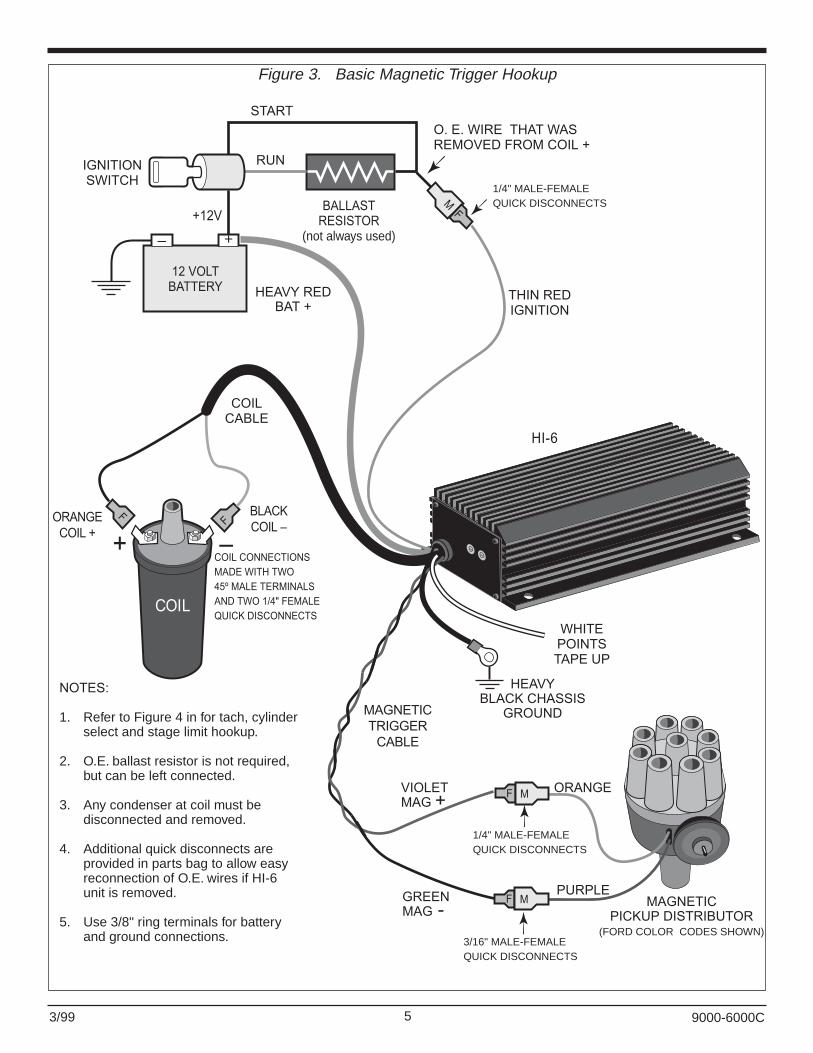
NOTES:
1. HI-6 battery and ground connectionsnot shown for clarity.
2. In most cases tach is wired to GM CoilConnector and will continue to function.
ORANGECOIL +
BLACKCOIL -
LATE MODELHEI COIL
WITHDUAL PLUGS
TOHI-6SAMEASABOVE
TOGM WIREHARNESS
BLACK COIL �
ORANGECOIL +
WHITE
WHITE
PINKPINK
WHITECOIL�
PINKIGNITION
WHITE
TACH
PINK IGNITION
COIL CABLE
1/4" MALEQUICK DISCONNECTSINSTALLED TO ALLOWRECONNECTION OF O.E.GM SYSTEM
THIN RED IGNITION
WHITE POINTS CUT GM HARNESS AT COIL PLUGS. USE SIX SETS OF 1/4" MALE-FEMALE QUICK DISCONNECTS. INSTALL JUMPERS AS SHOWN.
F
M
F
M
M
M
FM
FM
TOGM
DISTRIBUTOR
FM
FM
Figure 6. GM HEI with External Coil Hookup Distributorwithout Vacuum Advance Mechanism

103/99 9000-6000C
STEP 1PREPARE HI-6 MAGNETIC
TRIGGER CABLE
STEP 2REMOVE GM MODULE
AND HARNESS
STEP 3INSTALL HI-6 MAGNETIC TRIGGER CABLE
STEP 4CONNECT HI-6 TOGM COIL-IN-CAP
CABLEGROMMET
GROMMET
WIRECLAMPS
WIRECLAMP
1/4"MALE
TERMINAL
3/16"MALE
TERMINAL
TYPICALMODULE
MOUNTINGSCREW
GREENMAG �
VIOLETMAG +
GM MODULE
GM CABLEHARNESS
MAGNETIC PICK-UP
GREEN
WHITE
GMWHITE........GREEN.......
HI-6VIOLETGREEN
PICKUPCOLOR CODE
WIRECLAMP
WHITEPOINTS
TAPEUP
COILCABLE
MAGNETIC TRIGGERCABLE
GREENTACH
THIN REDIGNITION
USE 1/4" MALETERMINALS
BLACKCOIL �
ORANGECOIL +
1/4"FEMALE QUICKDISCONNECTS
BLACK 18"JUMPER TO
GROUND INSIDEDISTRIBUTOR
# 10 RINGTERMINAL
WARNING:
GM COIL MUST BE GROUNDEDWITH BLACK JUMPER WIRE AS SHOWN.GROUND TO HEI MODULE MOUNTINGSCREW INSIDE DISTRIBUTOR.
GM HEAVYRED OR PINK
IGNITION SWITCHWIRE
GMTACH WIRE
Figure 7. GM HEI with Coil-In-Cap Hookup Distributorwith Vacuum Advance Mechanism

113/99 9000-6000C
STEP 1PREPARE HI-6 MAGNETIC
TRIGGER CABLE
STEP 2REMOVE GM MODULE
AND HARNESS
STEP 3INSTALL HI-6 MAGNETIC TRIGGER CABLE
STEP 4CONNECT HI-6 TO
HEI COIL
CABLEGROMMET
GROMMET
WIRECLAMPS
WIRECLAMP
1/4"MALE
TERMINAL
3/16"MALE
TERMINAL
TYPICALMODULE
MOUNTINGSCREW
GREENMAG �
VIOLETMAG +
GM MODULE
GM CABLEHARNESS
MAGNETIC PICK-UP
GREEN
WHITE
GMWHITE........GREEN.......
HI-6VIOLETGREEN
PICKUPCOLOR CODE
WIRECLAMP
WHITEPOINTS
TAPEUP
COILCABLE
MAGNETIC TRIGGERCABLE
NOTE:
HI-6 BATTERY AND GROUNDCONNECTIONS NOT SHOWN FOR CLARITY.
GREENTACH
THIN REDIGNITIONGM HEAVY
RED OR PINKIGNITION SWITCH
WIREUSE 1/4" MALE
TERMINALSGM
TACH WIREEARLY HEI
COIL
BLACKCOIL �
ORANGECOIL +
1/4"FEMALEQUICKDISCON-NECTSF
F
Figure 8. GM HEI with External Coil Hookup Distributorwith Vacuum Advance Mechanism

123/99
MAGNETIC TRIGGEREDSYSTEMS
Use this hookup for all GM vehi-cles with 4 or 5 pin HEI modules(typically 1974-1980 cars and sometrucks up to 1986 using a distributorwith vacuum advance). You can usethis hookup for most vehicles withO.E. magnetic triggered ignitionthat do not have engine computersincluding AMC, Chrysler, Ford, GMMag Pulse (1968-74 Corvettes) andmany imports if the O.E. module isdamaged or has been removed. Usethis hookup for all crank trigger rac-ing applications.
The HI-6 will be magnetic trig-gered direct from the distributor pick-up or crank trigger using the mag-netic trigger cable.The white "points"trigger wire is not used and must be
taped up. Before starting, removeand identify all O.E. wires to the igni-tion coil. The O.E. module must bedisconnected from the magneticpickup and coil, but does not have tobe removed. Use the hookupsshown in Figures 7 and 8 for com-mon GM applications. Refer toFigure 3 for all other applications.Hookup is as follows:1. Connect HI-6 power and ground
wires. Connect blue cylinderselect wire as required for yourengine. Tape up white trigger wirewhich will not be used.
2. All except GM Mag Pulse.Remove O.E. wire(s) from Coil+terminal. Tie all these wirestogether and connect them to thered ignition switch wire from theHI-6.
3. GM Mag Pulse system only.Disconnect all O.E. wires fromCoil+ terminal and tape up. Trace"run" and "start" wires going fromignition switch to ballast resistor.Disconnect them from the ballastresistor, tie the wires togetherand connect them to the red igni-tion wire from the HI-6.
4. Remove O.E. wire(s) from Coil-terminal and tape up. If your vehi-cle has an electronic tach or fuelinjection, identify the wires thatgo to these systems and connectthem to the green tach outputwire from the HI-6.
5. Connect the HI-6 coil wires. GMMag Pulse system: you mustreplace the GM coil.Recommended coil is the CranePS91. Most other coils, includingGM external HEI coils, will work.
6. Disconnect O.E. module frommagnetic trigger. Connect the HI-6 magnetic trigger cable to thedistributor pickup or crank trigger.Refer to the chart on page 7 forMag+ and Mag- color codes. GMHEI: refer to Figures 7 or 8 foreasy hookup within the distributorusing supplied terminals.
1972-86 MOPARVEHICLES WITH 4 OR 5PIN MODULES
Use the hookup shown in Figure3. Most Mopar distributors use a 2pin rubber molded plug for the mag-netic pickup connection. Cut thewires going to this plug on the vehi-cle side of the wire harness. Thatway you can continue to use theplug. Connect the violet MAG+ wirefrom the HI-6 to the orange/whiteMopar pickup wire. Connect thegreen Mag- wire from the HI-6 to theblack Mopar pickup wire.Tape up thetwo wires that you cut on the vehicleharness.
You can remove the Mopar igni-tion module. Tape up the 4 or 5 pinplug on the vehicle harness.You canalso remove the ballast resistor.However, if you remove the ballastresistor, you must solder together allthe wires going to it.
9000-6000C
FORD E CORECOIL
FORD COILCONNECTOR
1/4" MALE TERMINALSRED &
LIGHT GREEN
DARK GREEN & YELLOW
1/4" FEMALEQUICK
DISCONNECTSF
F
HI-6
NOTES:
MAGNETIC TRIGGER CABLECUT SHORT AND TAPE UP
THIN REDIGNITION
WHITEPOINTS
ORANGECOIL +
BLACKCOIL -
COIL CABLE
1. HI-6 battery and ground connections notshown for clarity. Refer to Figure 4 forcylinder select and stage limit hookup.
2. In most cases tach is wired to Ford CoilConnector and will continue to function.
3. Turbo Coupe and Mustang Turbo will requiretach adapter P/N 6000-8910, refer to page18 for details.
Figure 9. Ford TFI with E-Core Coil Hookup

133/99
HONDA AND ACURAINTEGRA
Late model Honda and AcuraIntegra have either a distributor withinternal coil or an external coil. Ineither case, O.E. coils are not suit-able for use with the HI-6 and mustbe replaced with a Crane LX91 orsimilar coil. Internal coil distributorscan easily be converted to externalcoil by changing the distributor cap.
EXTERNAL COILRefer to Figure 10. Hookup is as fol-lows:1. Connect HI-6 power and ground
wires. Connect blue cylinderselect wire to thin red ignitionwire as shown in Figure 4 (for 4cylinder engines). Cut magnetictrigger cable short and tape upleads. Make sure magnetic trig-ger leads do not short together.Also tape up green tach wirewhich will not be used.
2. Identify and then cut wires off thetwo plugs on the Honda/AcuraO.E. coil. Leave enough wire onthe plugs so that they can bereconnected if required at a laterdate. Remove the Honda coil.Connect the HI-6 as shown. Useterminals and wire supplied in theparts bag. Note that some O.E.coils have only a single plug.Identify wires and connect similarto Figure 10. Most vehicles useblue color code for module outputand tach connection to Coil- ter-minal and black-yellow colorcode for switched +12V powerconnection to Coil+ terminal.Connect all O.E. blue wires to HI-6 white wire. Connect all O.E.black-yellow wires to HI-6 thin redwire.
3. Tach and fuel injection. Usuallythese systems will continue tofunction properly if left connectedas is. If the tach or fuel injectiondoesn’t work, read the section onTach Hookup on page 18. Hondaand Acura models generally donot require a tach adapter.
4. Connect the HI-6 coil cable to theLX91 coil. Use the plug suppliedwith the LX91. Depending onmounting location, you may have
to fabricate a longer high voltagecable to the distributor.
INTERNAL COIL CONVERSIONRefer to Figure 11. Hookup is as fol-lows:1. Remove the distributor cap and
dust shield. The dust shield isgenerally not required and can bediscarded. Note the O.E. wiringhookup within the distributor.Remove the O.E. coil (held inplace with two screws). Install a 2position terminal block as shown.You can use Radio-Shack P/N274-656 or similar part availablefrom electronic supply stores. Tiewrap the terminal block to one ofthe coil mounting holes or fabri-cate a support bracket from alu-minum channel material.Connect the O.E. wires that wentto Coil- and Coil+ to the terminalblock as shown.
2. You will require an external coildistributor cap. You can useHonda P/N 30102-PT3-A12 formost 92-97 Honda and AcuraIntegra models. Check the Craneweb site for availability of capadapters for other models. Drill a3/8” wire exit hole in the cap atthe location shown in the figure.Install the rubber grommet sup-plied in the parts bag.
3. Connect HI-6 power and groundwires. Connect blue cylinderselect wire to thin red ignitionwire as shown in Figure 4 (for 4cylinder engines). Cut magnetictrigger cable short and tape upleads. Make sure magnetic trig-ger leads do not short together.Also tape up green tach wirewhich will not be used.
4. Route the white HI-6 trigger wireand thin red HI-6 ignition(switched +12V) wires throughthe hole in the new distributor capand connect to the terminal blockas shown using two small ringterminals.
5. Tach and fuel injection. Usuallythese systems will continue tofunction properly if left connectedas is. If the tach or fuel injectiondoesn’t work, read the section onTach Hookup on page 18. Honda
and Acura models generally donot require a tach adapter.
6. Connect the HI-6 coil cable to theLX91 coil. Use the plug suppliedwith the LX91. You will have tofabricate a high voltage cable foruse between the coil and newdistributor cap.
EARLY VEHICLES WITHPOINTS
Use this hookup for points dis-tributors, including all aftermarketsingle and dual points distributors.The HI-6 will be triggered using thewhite "points" trigger input wire.Before starting, remove and identifyall O.E. wires to the ignition coil.Most applications will require cuttingand terminating the coil primarywires. Refer to Figure 2. Hookup isas follows:1. Connect HI-6 power and ground
wires. Connect blue cylinderselect wire as required for yourengine. Cut magnetic triggercable short and tape up leads.Make sure magnetic trigger leadsdo not short together.
2. Remove O.E. wire(s) from Coil+terminal. Tie all these wirestogether and connect them to thered ignition switch wire from theHI-6.
3. Remove O.E. wire(s) from Coil-terminal. Identify the wire thatgoes to the breaker points in thedistributor. Connect this wire tothe white points trigger wire fromthe HI-6. If your vehicle has anelectronic tach, there will proba-bly be an additional wire on theCoil- terminal. Identify any wiregoing to the tach and connect itto the green tach output wire fromthe HI-6.
4. Disconnect and remove the con-denser inside the distributor.
5. Connect the HI-6 coil wires.6. Special note on points.You will no
longer be able to use a dwellmeter. However, the points gap isnot critical when the points areonly used for triggering and donot carry any coil current. Use afeeler gauge and set the pointsgap to .016".
9000-6000C

143/99 9000-6000C
FM
FM
FM
F M
THIN REDIGNITION
NOTES:1. HI-6 Battery and ground connections not shown for clarity. Refer to Figure 4 for cylinder select & stage limit hookup.
2. Cut wires at Honda coil plugs and connect wire harness to HI-6 as shown.
3. Use LX91 coil in place of Honda coil.
BLACKCOIL �
ORANGECOIL +
USE PLUGSUPPLIEDWITH LX91
GREEN TACHTAPE UP
HI-6 UNIT
BLK-YEL
TACHBLUE
TO O.E.IGNITIONSWITCH
&TACH
TYPICAL1/4" MALE-FEMALE
QUICK DISCONNNECTS
WHITETRIGGER
TO O.E.IGNITIONMODULE
SWITCHED +12VBLK-YEL
MODULE OUTPUTBLUE
LENGTH OFWHITEWIRE
LENGTH OFRED WIRE
TOP VIEW OF HONDA COIL(SHOWN FOR REFERENCE ONLY)
COILCABLE
SMALLPLUG
LARGEPLUG
SWITCHED+12V
LX91
MAGNETIC TRIGGER CABLECUT SHORT AND TAPE UP
Figure 10. Honda External Coil Hookup

153/99 9000-6000C
NOTES:1. HI-6 Battery and ground connections not shown for clarity. Refer to Figure 4 for cylinder select & stage limit hookup.
2. Remove internal coil, use LX91 Coil and Honda Cap 30102-PT3-A12 for external coil. Drill hole thru cap for HI-6 wire exit.
BLACK COIL �
ORANGE COIL +
LX91 COIL
USE PLUGSUPPLIEDWITH LX91
GREEN TACHTAPE UP
HI-6 UNIT
TO O.E.HARNESS
TO O.E.HARNESS
TRIGGER
WHITETRIGGER
2 POSITIONTERMINAL
BLOCK
+12V
+12V
REDSWITCHED +12V
REDSWITCHED +12V
TACHSIGNAL
MODULEOUTPUT
INPUT FROMECU
IGNITION MODULE
O.E. HOOKUP
O.E.COIL
+ -
DRILL 3/8" HOLE AND INSTALLRUBBER GROMMET FOR WIRE EXIT
HONDA30102-PT3 A12 CAP
MAGNETIC TRIGGER CABLECUT SHORT AND TAPE UP
COIL CABLE
Figure 11. Honda Internal Coil Hookup and Conversion to External Coil

163/99
AFTERMARKETIGNITIONS
Crane XR700 and XR3000 andother aftermarket points conversionsystems such as the Mallory Unilite,are compatible with the HI-6.
Aftermarket magnetic triggerconversion systems such as Accel,Chrysler, and Hayes Stinger: theignition module sold with these sys-tems is not required. Disconnect andremove the aftermarket ignitionmodule and trigger the HI-6 directfrom the magnetic pickup. Refer tothe Magnetic Triggered Systemssection on page 12.
Aftermarket CD systems suchas Accel, Holley, Jacobs, Malloryand MSD-6 units are not compatiblewith the Crane HI-6. Remove theseaftermarket units and then use theHI-6 hookup recommended for theparticular vehicle.
VEHICLES WITHCRANE XR700 ANDXR3000
Use the hookup shown in Figure12 if you are adding an HI-6 to avehicle where the O.E. ignition hasbeen replaced with a Crane XR700or XR3000 optical trigger conver-sion. This is highly recommended forolder points equipped vehicles, as iteliminates the problems with pointsbounce and wear. It will also providemore stable timing.Tach and fuel injection: in mostcases the tach and fuel injection (ifequipped) wires would originallyhave been connected to Coil-. Traceout these wires and connect them tothe green tach output wire from theHI-6. If this doesn't work, you mayneed tach adapter P/N 6000-8920.
VEHICLES WITHMALLORY UNILITE
Use the hookup shown in Figure13 if you are adding an HI-6 to avehicle equipped with a MalloryUnilite system.Tach and fuel injection: in mostcases the tach and fuel injection (ifequipped) wires would originallyhave been connected to Coil-. Traceout these wires and connect them to
the green tach output wire from theHI-6. If this doesn't work, you mayneed tach adapter P/N 6000-8910.
FINAL CHECKBefore starting the engine for the
first time, double check all electricalconnections and set a safe rev limit.Start the engine and check the igni-tion timing. The timing may change afew degrees after HI-6 installation.Reset timing to manufacturer's spec-ifications. If a large difference isnoted, Mag+ and Mag- may bereversed.
REV LIMITER - ALLEXCEPT HI-6DS ANDHI-6DSR MODELS
Select a safe stage rev limit thatis less than the red line for yourengine. Set the rotary switches on
the HI-6 to the selected stage revlimit. Settings are X100 engine RPM(i.e. 22 = 2,200 RPM). The rev limitcan be set over the range of 600 to9,900 RPM. Use the small screw-driver supplied in the parts bag to setthe switches. Special switch settingsare:
00 Disables the internal rev limiter and allows operationabove 9,900 RPM.
01 Disables multiple sparkand internal rev limiter.
02 Disables the internal revlimiter and timing retard.Special compatibility mode for external Crane rev limiters and engine controls.
9000-6000C
– +
12 VOLTBATTERY
IGNITIONSWITCH
BALLASTRESISTOR
(not always used)
+12V
RUN
STARTO. E. WIRE THAT WASREMOVED FROM COIL +
HI-6WHITEPOINTS
TRIGGER
THIN REDIGNITION
REDIGNITION
HEAVY REDBAT +
SEENOTE 1
COIL
+ �F
F
BLACKCOIL �
ORANGECOIL +
COILCABLE
SEENOTE 1
FM
MAGNETIC TRIGGER CABLECUT SHORT AND TAPE UP
HEAVY BLACKCHASSIS GROUND
HEAVY BLACKCHASSIS GROUND
FM
NOTES:1. Connections are made with two
sets of 1/4" male -female quickdisconnects.
2. Refer to Figure 4 for tach, cylinderselect, and stage limit hookup.
3. O.E. ballast resistor is not required,but can be left connected.
4. Refer to XR700/XR3000 instructionsfor optical trigger installation withindistributor.
5. Use 3/8" ring terminals for batteryand ground connections.
COIL CONNECTIONSMADE WITH TWO45º MALE TERMINALSAND TWO 1/4" FEMALEQUICK DISCONNECTS
TO OPTICALTRIGGERWITHIN
DISTRIBUTOR(NOT SHOWN)
XR700 OR XR3000IGNITION MODULE
Figure 12. Triggering HI-6 from XR700 or XR3000 Module

173/99 9000-6000C
03 Tach test step mode.Causes tach to step from 1,000 to 10,000 RPM in1,000 RPM increments.
04 Tach test ramp mode.Causes tach to slowly rampfrom 200 to 10,000 RPM.
05 Not used.
The HI-6 reads rev limit settingswhen ignition power is first turnedon. If you change the rev limit set-ting, you must turn the ignition switchoff momentarily for the new setting tobecome effective.
REV LIMITER - HI-6DSAND HI-6DSR MODELS
Select safe stage and maximumrev limits that are less than the red
line for your engine. Set the rotaryswitches on the HI-6 to the selectedrev limits. Settings are X100 engineRPM (i.e. 22 = 2,200 RPM). The revlimits can be set over the range of600 to 9,900 RPM. Use the smallscrewdriver supplied in the parts bagto set the switches. Special stage revlimit switch settings are:
00 Disables the internal rev limiter and allows operationabove 9,900 RPM.
01 Disables multiple sparkand internal rev limiter.
02 Disables the internal revlimiter and timing retard.Special compatibility modefor external Crane rev limiters and engine controls.
03 Tach test. Note that the tachtest mode must be set on the maximum rev limit switches as described below.
04- 05 Not used.
Special maximum rev limit switchsettings used in tach test mode only(stage limit set to 03):
01 Tach test step mode.Causes tach to step from 1,000 to 10,000 RPM in1000 RPM increments.
02 Tach test ramp mode.Causes tach to slowly rampfrom 200 to 10,000 RPM.
03-99 Constant tach output at set RPM (i.e. 50 = 5,000 RPM).
The HI-6 reads rev limit settingswhen ignition power is first turnedon. If you change the rev limit set-ting, you must turn the ignition switchoff momentarily for the new setting tobecome effective. The exception iswhen tach test is selected via stagelimit setting 03. The tach test modeset on the maximum limit switchescan be changed on-the-fly.
If you do not require the stagelimit feature, set the desired maxi-mum rev limit, leave the stage limitswitches set to 00 and tape up theyellow/white stage input wire.
TROUBLESHOOTING
TACH TEST FEATURE Selection of the tach test mode is
explained in Rev Limiter section start-ing on page 16. During tach test mode,the green tach wire is used to output atach test signal when the ignitionswitch is turned on. Note that theengine will not run if tach test mode isselected. To leave tach test modemode, you must change back to nor-mal rev limit switch settings and turnthe ignition switch off and then onagain.
– +
12 VOLTBATTERY
IGNITIONSWITCH
BALLASTRESISTOR
(not always used)
+12V
RUN
STARTO. E. WIRE THAT WASREMOVED FROM COIL +
HI-6WHITEPOINTS
TRIGGER
THIN REDIGNITION
HEAVY REDBAT +
SEENOTE 1
COIL
+ �F
F BLACKCOIL �
ORANGECOIL +
COILCABLE
SEENOTE 1
FM
MAGNETIC TRIGGER CABLECUT SHORT AND TAPE UP
HEAVY BLACKCHASSIS GROUND
BROWNCHASSIS GROUND
FM
NOTES:1. Connections are made with two sets
of 1/4" male -female quick disconnects.
2. Refer to Figure 4 for tach, cylinderselect, and stage limit hookup.
3. O.E. ballast resistor is not required,but can be left connected.
4. Refer to Mallory Unilite instructions forinstallation within the distributor.
5. Any condenser at coil must beremoved.
6. Use 3/8" ring terminals for batteryand ground connections.
COIL CONNECTIONSMADE WITH TWO45º MALE TERMINALSAND TWO 1/4" FEMALEQUICK DISCONNECTS
DISTRIBUTOR WITHMALLORY
UNILITE SYSTEM
REDIGNITION
GREENTRIGGEROUTPUT
Figure 13. Triggering HI-6 from Mallory Unilite System
183/99 9000-6000C
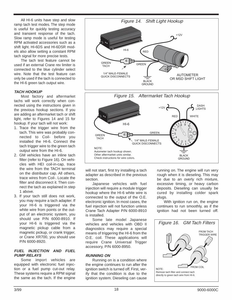
All HI-6 units have step and slowramp tach test modes. The step modeis useful for quickly testing accuracyand transient response of the tach.Slow ramp mode is useful for testingRPM activated accessories such as ashift light. HI-6DS and HI-6DSR mod-els also allow setting a constant RPMtach signal for more precise tests.
The tach test feature cannot beused if an external Crane rev limiter isconnected to the blue cylinder selectwire. Note that the test feature canonly be used if the tach is connected tothe HI-6 green tach output wire.
TACH HOOKUP Most factory and aftermarket
tachs will work correctly when con-nected using the instructions given inthe previous hookup sections. If youare adding an aftermarket tach or shiftlight, refer to Figures 14 and 15 forhookup. If your tach will not work:1. Trace the trigger wire from the
tach. This wire was probably con-nected to Coil- before youinstalled the HI-6. Connect thetach trigger wire to the green tachoutput wire from the HI-6.
2. GM vehicles have an inline tachfilter (refer to Figure 16). On vehi-cles with HEI coil-in-cap, tracethe wire from the TACH terminalon the distributor cap. All others,trace wires from Coil-. Locate thefilter and disconnect it. Then con-nect the tach as explained in step1 above.
3. If your tach still does not work,you may require a tach adapter. Ifyour HI-6 is triggered via thewhite wire from points or the out-put of an electronic system, youshould use P/N 6000-8910. Ifyour HI-6 is triggered via themagnetic pickup cable from amagnetic pickup, or crank trigger,or Crane XR700, you should useP/N 6000-8920.
FUEL INJECTION AND FUELPUMP RELAYS
Some import vehicles areequipped with electronic fuel injec-tion or a fuel pump cut-out relay.These systems require a RPM signalthe same as the tach. If the engine
will not start, first try installing a tachadapter as described in the previoussection.
Japanese vehicles with fuelinjection will require a module triggerhookup where the HI-6 white wire isconnected to the output of the O.E.electronic ignition. In most cases, thefuel injection will not function unlessCrane Tach Adapter P/N 6000-8910is installed.
Some late model Japanesevehicles and vehicles with OBD IIdiagnostics may require a specialmeans of triggering the HI-6 from theO.E. coil. These applications willrequire Crane Universal Triggeraccessory, P/N 6000-8950.
RUNNING ONRunning on is a condition where
the engine continues to run after theignition switch is turned off. First, ver-ify that the condition is due to theignition system. Dieseling can cause
running on. The engine will run veryrough when it is dieseling. This maybe due to an overly rich mixture,excessive timing, or heavy carbondeposits. Dieseling can usually becured by installing colder sparkplugs.
With ignition run on, the enginecontinues to run smoothly, as if theignition had not been turned off.
RED
+12V
BLACKGROUND
GREEN
AUTOMETEROR MSD SHIFT LIGHT
FM
GREENTACH
1/4" MALE-FEMALEQUICK DISCONNECTS
HI-6
Figure 14. Shift Light Hookup
RED WHITE
BLACKGROUND
GREENFM
GREENTACH
1/4" MALE-FEMALEQUICK DISCONNECTS
+12VDASH
LIGHTS
0123
456
78 9 10
RPM
NOTE:Autometer tach hookup shown.Other aftermarket units similar.Check instructions for wire colors.
HI-6
Figure 15. Aftermarket Tach Hookup
FROM TACHTRIGGER WIRE
FROM COILNOTE:Remove tach filter and connect tachdirectly to green tach wire from HI-6.
Figure 16. GM Tach Filters

193/99
Ignition run on is caused from cur-rent leaking back to the HI-6 throughthe charging system indicator. Tosolve this problem, install the diodesupplied in the parts kit on the volt-age regulator.
GM or Ford with external voltageregulator: refer to Figure 17. For GMvehicles, install the diode on the #4
terminal. For Ford vehicles, installthe diode on the terminal marked "I".GM vehicles with Delcotron alterna-tor and internal regulator: refer toFigure 18. Install the diode in the thinbrown wire going to the indicatorlight.
Installation of the diode may notcorrect the run on problem on some
AMC vehicles. Refer to Figure 19.Use a 1973-76 Chrysler dual ballastresistor (available at most partsstores). Solder a jumper wire acrossboth terminals on one end. Thenconnect the terminals on the otherend to ground and to the red ignitionswitch wire from the HI-6.
RADIO NOISEA powerful multiple spark sys-
tem such as the HI-6 will tend togenerate more noise than the O.E.ignition. To some extent this isunavoidable, but steps can be takento reduce the noise level.
Radio frequency (RF) noise isradiated from coil and spark plugwires. RF noise primarily affects AMand CB radios. Conducted noiseappears as a whine that followsengine RPM and may affect all sys-tems including tape players and FMradio. Use the following check list toreduce RF noise:1. Make sure a ground strap is
installed between the engine andchassis.
2. Make sure that radio, tape andCB systems are grounded directto the chassis.
3. Mount the HI-6 unit as far awayas possible from the antenna(including windshield antenna)and other electronic devices.Make sure the HI-6 is groundeddirect to the chassis. Keep theground wire short, preferably nomore than 6".
4. Replace spark plug wires withspiral core type wire. Replacerotor and cap. Apply a smallamount of silicone dielectricgrease to the rotor tip and to allhigh voltage terminals. Use onlyresistor spark plugs when run-ning on the street.
Conducted noise from the HI-6is carried through +12 volt powerconnections. Conducted noise canbe reduced by installing a power linenoise filter (available at RadioShack) near the affected radio.
9000-6000C
NOTE:USE BUTT SPLICES TO CONNECT DIODE, THEN WRAP WITH ELECTRICAL TAPE.
FORD VEHICLESATTACH DIODE TOTERMINAL MARKED " I"
BUTTSPLICE
BUTTSPLICE
EARLY GM VEHICLESATTACH DIODE TO TERMINAL MARKED "4"
1N4007 DIODE
INDICATORLAMP
VOLTAGEREGULATOR
1
Figure 17. Diode Installation on External Regulator
No. 2TERMINAL
�BAT�TERMINAL
1973-83 GMDELCOTRON
No. 1TERMINAL
NOTE:
USE BUTT SPLICES TO CONNECT DIODE, THEN WRAP WITH ELECTRICAL TAPE.
BROWN WIRETo No. 1 TERMINAL
INDICATORLAMP
BUTTSPLICE
BUTTSPLICE
1N4007 DIODE
Figure 18. Diode Installation on Delcotron Alternator
CHASSISGROUND
HI-6 JUMPERWIRE
IGNITIONSWITCH
CHRYSLER DUALBALLAST RESISTOR
NOTE:Other wires not shown for clarity.
THIN REDIGNITION
Figure 19. Run-On Fix Using Chrysler Ballast Resistor
203/99
NOISE SUPPRESSION ON STAGELIMIT INPUT
In some applications the stageinput (yellow/white wire) is connect-ed to a switch that also controls aline lock or transmission brake sole-noid valve. When the switch opensand current flow to the solenoid isinterrupted, electrical transients (upto 500 volts) occur. These transientscan lead to glitches in on-board elec-tronics. Arcing also occurs in switchcontacts greatly decreasing switchlife and possibly resulting in erraticoperation. This may cause inconsis-tent launch and 60 foot times.
The solution is to install the sup-plied surge absorber. It will limit themaximum voltage to about 40 volts.The surge absorber appears as asmall 1/2 inch diameter disk with twowire leads. Solder one lead to thestage switch and the other lead to aterminal that connects to ground asshown in Figure 4.
POWER SUPPLY FILTERCAPACITOR HOOKUP
A filter capacitor on the 12 voltsupply is recommended if the HI-6power wires are extended, the bat-tery is located in the trunk, or sole-noid valves drawing more than 10amps are used. Use a minimum38,000 microfarad (uF) 16 voltcapacitor such as Crane P/N 9000-0014. Install the capacitor across the12 volt supply (heavy read wire) andchassis ground near the HI-6 unit.
TROUBLESHOOTINGHI-6 OPERATION
Did the engine run properlybefore installation of the HI-6? If not,remove the HI-6, reinstall the O.E.ignition or another known good unitand then find and correct the originalproblem. Did the HI-6 function cor-rectly before the problem occurred?If the answer is yes, did you changeanything that may have affected it? Ifyou connected an external control orchanged ignition coils, try going backto the last setup that worked OK tohelp isolate the problem.
If the engine will not start, orruns rough or intermittently, use thefollowing check list steps:
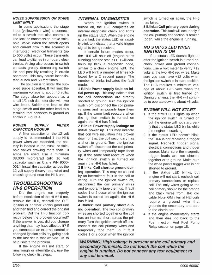
INTERNAL DIAGNOSTICSWhen the ignition switch is
turned on, the HI-6 completes aninternal diagnostic check and lightsup the status LED. When the engineis cranked, the status LED will rapid-ly blink to indicate that a valid triggersignal is being received.
If certain failure modes occur,the HI-6 will shut off (engine stopsrunning) and the status LED will con-tinuously blink a diagnostic code,similar to a check engine light. TheLED will blink a number of times fol-lowed by a 2 second pause. Thenumber of blinks indicates the faultmode:1 Blink: Power supply fault on ini-tial power up. This may indicate thatthe coil connections are directlyshorted to ground. Turn the ignitionswitch off, disconnect the coil prima-ry wires and temporarily tape themup. If the same fault reoccurs whenthe ignition switch is turned onagain, the HI-6 has failed.2 Blinks: Power supply leakage oninitial power up. This may indicatethat coil wire insulation has brokendown or that the coil secondary hasa short to ground. Turn the ignitionswitch off, disconnect the coil prima-ry wires and temporarily tape themup. If the same fault reoccurs whenthe ignition switch is turned onagain, the HI-6 has failed.3 Blinks: Coil short to ground dur-ing operation. This may be causedby an intermittent fault in the coil orwiring. Turn the ignition switch off,disconnect the coil primary wiresand temporarily tape them up. If faultcodes 1 or 2 occur when the ignitionswitch is turned on again, the HI-6has failed.4 Blinks: Coil primary short dur-ing operation. The two coil primarywires are shorted together or the coilhas an internal short across the pri-mary. Turn the ignition switch off, dis-connect the coil primary wires andtemporarily tape them up. If faultcodes 1 or 2 occur when the ignition
switch is turned on again, the HI-6has failed.5 Blinks: Coil primary open duringoperation. This fault will occur only ifthe coil primary connection is broken(open) while the engine is running.
NO STATUS LED WHENIGNITION IS ON
If the status LED doesn't light upafter the ignition switch is turned on,check power and ground connec-tions. Use a volt meter to verify +12volts at the two HI-6 red wires. Makesure you also have +12 volts whenthe ignition switch is in start position.The HI-6 requires a minimum volt-age of about +9.5 volts when theignition switch is first turned on.During cranking, the HI-6 will contin-ue to operate down to about +5 volts.
ENGINE WILL NOT START1. If the status LED lights up when
the ignition switch is turned onbut the engine will not start, veri-fy that the status LED blinks whilethe engine is cranking.
2. If the status LED doesn't blink,the HI-6 is not receiving a triggersignal. Recheck trigger signalelectrical connections and triggersource. Make sure the magnetictrigger leads are not shortedtogether or to ground. Make surethe white points trigger wire is notshorted to ground.
3. If the status LED blinks, butengine will not start, recheck coilprimary connections or replacecoil. The only wires going to thecoil primary should be the orangeand black wires from HI-6 coilcable. Note: GM internal HEI coilsrequire a ground wire thatgrounds the secondary and coreto the distributor.
4. If the engine momentarily startsand then dies, go back to theFuel Injection And Fuel PumpRelay section on page 18.
9000-6000C
WARNING: High voltage is present at the coil primary andsecondary Terminals. Do not touch the coil while theengine is running. Do not connect any test equipment toany coil terminal.

213/99
CHECKING FOR SPARKTo crank the engine without
starting or to check for spark, use aKD Tools HEI test plug. The test plugcomes with an alligator clip that canbe attached to chassis ground. Makeup a length of spark plug wire to con-nect the test plug to the coil.
MISFIRE OR INTERMITTENTOPERATION1. A weak battery may cause misfire
or intermittent operation, espe-cially at high RPM, if battery volt-age drops below +10 volts. If indoubt, charge or replace the bat-tery.
2. Field experience has shown thatmisfire at high RPM is usually notan electrical problem within theHI-6. Coil failure, including inter-nal arcing or arcing at the highvoltage terminal, is a commoncause. Arcing across spark plugboots or the distributor cap is alsocommon.
3. Route all magnetic trigger con-nections away from any otherwiring, especially HI-6 coil cableand any high voltage coil andspark plug wires.
4. Replace spark plugs. Check thatspark plugs are proper type, heatrange, and gap size.
5. Replace distributor high voltagerotor and cap.
6. Replace spark plug wires. Do notuse solid core wires or high resis-tance wires. Use only spiral coretype wires.
7. Check for loose or corroded con-nections and broken wires atmagnetic pickup, HI-6 unit, coil,and distributor cap. Also checkdistributor for loose, missing, orjamming parts in pickup oradvance mechanism (if used).Magnetic pickups and crank trig-ger: check for proper air gap.
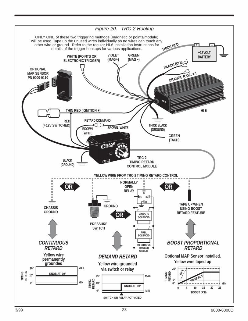
The HI-6 uses thebrown/white wire as its retardcommand input. Connect thebrown/white wire from the HI-6 tothe TRC-2 as shown in Figure 20(page 23) only. Read theseinstructions carefully before start-ing installation.
INTRODUCTIONThe Crane Cams TRC-2 is an
accessory for HI-6 systems thatprovides driver-adjustable retard.The TRC-2 can provide continuoustiming retard (0° - 20°), retard usinga switch (0° - 20°), or retard propor-tional to boost (up to 4° per psi) onsupercharger or turbocharger instal-lations (with an optional boost sen-sor, not included).
INSTALLATIONComplete the installation of the
HI-6 ignition module prior toinstalling the TRC-2. Figure 20shows hookup of the TRC-2 to theHI-6. The red wire from the TRC-2is connected to a key switched, +12volt supply. You may splice it intothe thin red wire on the HI-6. Theyellow wire from the TRC is con-nected directly to ground for contin-uous retard control, through aboost/nitrous switch to ground forretard on demand, or taped offwhen using the optional boost sen-sor. When using retard on demand,the switch must complete the circuitto ground to activate the retard (usea normally open switch or relay).
FINAL CHECKBefore starting the engine for
the first time, double check all elec-trical connections. Set the TRC-2knob to 0° (fully counterclockwise),then start the engine and check theignition timing. The timing maychange a few degrees after installa-tion. Reset timing to manufacturer’sspecs. Upon starting the engine, theLED on the TRC-2 module will be litonly if the yellow wire is grounded.
OPERATIONThe TRC-2 module allows you
to adjust the amount of retard pro-duced by the HI-6. It also containsan LED that indicates when theretard function is activated. Howyou use the TRC-2 depends onwhether you have connected it forcontinuous, demand, or boost-pro-portional retard.
CONTINUOUS RETARDRefer to Figure 20. Connect the
yellow wire from the TRC-2 directlyto chassis ground for continuousretard. Since the retard feature isactive all the time, the LED on theTRC-2 will be illuminated wheneverthe key is on. Turning the knob fullycounterclockwise (0°) produces noretard. Turning the knob clockwiseincreases the retard up to 20°. TheTRC-2 is approximately linearthroughout its range, so half scaleis about 10° of retard. For preciseretard calibration, you must use ahigh-quality timing light.
9000-6000C
WARNING: Never crankthe engine with the coilhigh voltage wire or anyspark plug wiredisconnected.
SUPPLEMENT - TRC-2 Timing RetardControl Installation and Operation
NOTE: The brown/white retard input wire on current HI-6units may be left unconnected if the retard feature is notused. Please note that components from older HI-6TRsystems are not compatible with the current HI-6 series.Do not connect any HI-6 or TRC-2 unit with a brown/whiteretard wire to an HI-6TR series device with a brown retardwire.

223/99
The uses for this type of timingcontrol include adjusting timing toprevent knock because of inferiorfuel quality or insufficient octane,altitude adjustments, etc. As youdrive, you can apply just the amountof retard required to prevent sparkknock and optimize fuel economy. Inracing applications the retard con-trol can be used to tune the vehicleto specific track and atmosphericconditions. The TRC-2 also may beused on vehicles with mechanicaladvance distributor or computerengine controls to change the totalignition timing.
DEMAND RETARD Refer to Figure 20. Connect the
yellow wire from the TRC-2 to anormally open switch or relay thatwill complete a path to chassisground when retard is desired.Example: A pressure switch thatcloses at a certain boost level. TheLED on the TRC-2 will light upwhen the yellow wire is grounded.When the LED is lit, the retard fea-ture is active and the spark isretarded by the amount set on theTRC-2 knob from 0° - 20°. TheTRC-2 is approximately linearthroughout its range, so half scaleis abut 10° of retard. For preciseretard calibration, you must use ahigh-quality timing light. The dia-gram below shows an example withthe knob set for 10° of retard.
This type of timing control isgreat for nitrous oxide and super-charged applications, or any vehiclethat requires adjustable retard. Fornitrous applications, Figure 20shows how a normally-open relay isused to ground the yellow wirewhen nitrous and fuel solenoids areactivated. The pin numbers are for astandard automotive relay such asRadio Shack P/N 275-226. Figure20 also shows a pressure activatedswitch designed to retard timingwhen the boost pressure reaches apre-set value. NAPA Balkamp offerstwo adjustable pressure switches:P/N 701-1591 (3-7 psig range) andP/N 701-1603 (1.1-3 psig range).
Demand retard mode is also greatfor crank-trigger systems where amomentary start retard is required.A manual switch or a normally openrelay energized by the starter sole-noid can be used to ground the yel-low wire during cranking to provideup to 20° of starting retard. Oncethe switch is released, timingreturns to normal.
BOOST PROPORTIONALRETARD
Refer to Figure 20. An optionalboost sensor (Crane P/N 9000-0110) is required for boost propor-tional retard. This sensor is arugged unit that can measure pres-sures up to 15 psi above normalatmospheric pressure. The harnessand mating connector are supplied.The yellow wire should be taped up.Use 1/4” I.D. fuel hose to plumb thesensor to your intake manifold.
When the boost sensor is con-nected, the retard setting on theTRC-2 now refers to a retard slopefrom 0° to 4° per psi of boost.Simply divide the knob setting by 5to determine the retard slope (seeFigure 20 below). For example, ifthe knob is set to 5° the retardslope is 1° per psi and at 5 psi ofboost the retard is 5°. As boostrises further, the retard increases atthis same slope up to a maximumof 20°. If the boost level exceeds 15psi, the retard levels off as shown inFigure 20 below (sensor damagemay occur above 18 psi).
The status LED on the TRC-2illuminates when retard is beingapplied. Under most conditions, thisoccurs between 0.5 and 1.0 psi ofboost. As boost rises, retard riseswith a slope determined by theknob setting. Note that the retardslope stops rising when the boostreaches 15 psi or the retard reach-es 20°. The TRC-2 is approximatelylinear throughout its range, but forprecise retard calibration use a tim-ing light to obtain retard value.
TROUBLESHOOTINGDid the engine run properly
before installation of the TRC-2? Ifnot, remove the both the TRC-2 andHI-6 units, reinstall the OEM ignitionor another known good unit andthen find and correct the originalproblem. Make sure the HI-6 sys-tem functions properly beforeinstalling or troubleshooting theTRC-2 accessory. Did the TRC-2function correctly before the prob-lem occurred? If the answer is yes,did you change anything that mayhave affected it? If you connectedan external control or changed igni-tion coils, try going back to the lastsetup that worked to help isolatethe problem. Refer to the HI-6installation instructions for moredetails, including the use of the HI-6’s built-in diagnostic LED locatedon the ignition module.
If you are not getting theamount of retard you expect, checkthe LED on the TRC-2 module; itlights up when retard is beingapplied. If it does not light up incontinuous or demand retardmodes, check the yellow wire fromthe TRC-2. It must contact a goodchassis ground when retard isneeded. Also re-check thebrown/white wire connection fromthe TRC-2 to the HI-6.
In boost retard mode theamount of retard should be propor-tional to the pressure measured bythe optional MAP sensor. Theamount of retard may vary in agiven application if local atmospher-ic (barometric) pressure changessignificantly. This occurs most oftenwith a change in altitude of 1000feet or more.
If the TRC-2 settings seem tobe off, check the travel of the knobfrom no-retard (0°) to maximum(20°). Make sure that the pointer isproperly aligned when the knob isat each limit.
9000-6000C
233/99 9000-6000C
RED(+12V SWITCHED)
OPTIONALMAP SENSORPN 9000-0110
THICK BLACK(GROUND)
NITROUSSOLENOID
FUELSOLENOID
TO NITROUSTRIGGERCIRCUIT
8786
30
85
BOOST (PSI)
20°
5°0°
0 5 10 15 20 25MINMIN
MAX
MAX
KNOB AT 5°
TIM
ING
RETA
RD
TIM
ING
RETA
RD TIM
ING
RETA
RD
20°
10°
0°
KNOB AT 10°
MIN
MAX
SWITCH OR RELAY ACTIVATED
20°
10°
0°
KNOB AT 10°
PRESSURESWITCH
NORMALLYOPENRELAY
CHASSISGROUND
GROUND
RETARD
TRC-2
OR OR
OR
TRC-2TIMING RETARD
CONTROL MODULE
TAPE UP WHENUSING BOOST
RETARD FEATURE
HI-6
YELLOW WIRE FROM TRC-2 TIMING RETARD CONTROL
ONLY ONE of these two triggering methods (magnetic or points/module)will be used. Tape up the unused wires individually so no wires can touch any
other wire or ground. Refer to the regular HI-6 Installation Instructions fordetails of the trigger hookups for various applications.
THIN RED (IGNITION +)
BLACK(GROUND)
RETARD COMMAND
BROWN/ WHITE
BROWN / WHITE
BLACK (COIL - )
ORANGE (COIL + )
GREEN(TACH)
THICK RED –+
+12 VOLTBATTERYVIOLET
(MAG+)GREEN(MAG -)
WHITE (POINTS ORELECTRONIC TRIGGER)
CONTINUOUSRETARD
DEMAND RETARD
BOOST PROPORTIONALRETARD
Yellow wirepermanently
grounded Yellow wire groundedvia switch or relay
Optional MAP Sensor installed.Yellow wire taped up
Figure 20. TRC-2 Hookup

243/99 9000-6000C


![ei2BBBB - rrtechnical.inforrtechnical.info/sz/sz87/ei2.pdf · 02/10/08 TSD 6000 1990 - 2000 [English] / Twin Ignition Distributor Belt Replacement Page 1 (OID =](https://static.fdocuments.us/doc/165x107/6045a374b164890f00182833/ei2bbbb-021008-tsd-6000-1990-2000-english-twin-ignition-distributor-belt.jpg)

