Installation Instructions -...
36
1 607E - -A PREFERREDt 15 SEER 2-STAGE PACKAGED HEAT PUMP SYSTEM WITH PURONr (R -410A) REFRIGERANT SINGLE AND THREE PHASE 2 -5 NOMINAL TONS (SIZES 24 -60) Installation Instructions NOTE: Read the entire instruction manual before starting the installation. NOTE: Installer: Make sure the Owner’s Manual and Service Instructions are left with the unit after installation. TABLE OF CONTENTS PAGE SAFETY CONSIDERATIONS 1 ......................... INTRODUCTION 2 ................................... RECEIVING AND INSTALLATION 2--10 ................. Check Equipment 2 .................................. Identify Unit 2 .................................... Inspect Shipment 2 ................................. Provide Unit Support 2 ............................... Roof Curb 2 ...................................... Slab Mount 2 ..................................... Provide Clearances 6 ................................. Field Fabricate Ductwork 6 ............................ Rig and Place Unit 6 ................................. Inspection 7 ...................................... Rigging/Lifting of Unit 7 ............................ Connect Condensate Drain 7 ........................... Install Duct Connections 7 ............................. Configuring Units for Downflow (Vertical) Discharge 8 .... Install Electrical Connections 9 ......................... High--Voltage Connections 9 ......................... Special Procedures for 208v Operation 9 ................ Control Voltage Connections 9 ........................ Standard Connection 9 .............................. Transformer Protection 10 ........................... PRE--START--UP 11 ................................... START--UP 11--13 ..................................... Check Cooling and Heating Control Operation 11 .......... Check for Refrigerant Leaks 11 ......................... Start--Up Adjustments 12 .............................. Checking and Adjusting Refrigerant Charge 12 ........... Indoor Airflow and Airflow Adjustments 12 ............. Low Stage Cooling 13 .............................. High Stage Cooling 13 .............................. High Stage Enhanced Dehumidification Cooling (208/230 Vac Models) 13 ....................................... Continuous Fan 13 ................................. Sequence of Operation 13 ........................... Defrost Control 13 ................................... Quiet Shift 13 ..................................... Defrost 13 ....................................... MAINTENANCE 29--32 ................................ Air Filter 29 ...................................... Indoor Blower and Motor 29 ......................... Outdoor Coil, Indoor Coil, and Condensate Drain Pan 30 ... Outdoor Fan 30 ................................... Electrical Controls and Wiring 30 ..................... Refrigerant Circuit 31 ............................... A09033 Fig. 1 -- Unit607E----A Evaporator Airflow 31 .............................. Metering Device 31 ................................ System Information 32 ................................ Loss of Charge Switch 32 ............................ Check Defrost Thermostat 32 ......................... TROUBLESHOOTING 32 .............................. START--UP CHECKLIST 32 ............................ SAFETY CONSIDERATIONS Improper installation adjustment, alteration, service, maintenance, or use can cause explosion, fire, electrical shock, or other conditions which may cause death, personal injury, or property damage. Consult a qualified installer, service agency, or your distributor or branch for information or assistance. The qualified installer or agency must use factory--authorized kits or accessories when modifying this product Refer to the individual instructions packaged with the kits or accessories when installing. Follow all safety codes. Wear safety glasses, protective clothing, and work gloves. Use quenching cloth for brazing operations. Have a fire extinguisher available. Read these instructions thoroughly and follow all warnings or cautions included in literature and attached to the unit. Consult local building codes, the current editions of the National Electrical Code (NEC) NFPA 70. In Canada refer to the current editions of the Canadian electrical Code CSA C22.1. Recognize safety information. This is the safety--alert symbol . When you see this symbol on the unit and in instructions or manuals, be alert to the potential for personal injury. Understand these signal words; DANGER, WARNING, and CAUTION. These words are used with the safety--alert symbol. DANGER identifies the most serious hazards which will result in severe personal injury or death. WARNING signifies hazards which could result in personal injury or death. CAUTION is used to identify unsafe practices which may result in minor personal injury or product and property damage. NOTE is used to highlight suggestions which will result in enhanced installation, reliability, or operation.
Transcript of Installation Instructions -...

1
607E----APREFERREDt 15 SEER 2--STAGE PACKAGED HEAT PUMP SYSTEMWITH PURONr (R--410A) REFRIGERANTSINGLE AND THREE PHASE2--5 NOMINAL TONS (SIZES 24--60)
Installation InstructionsNOTE: Read the entire instruction manual before starting theinstallation.
NOTE: Installer: Make sure the Owner’s Manual and ServiceInstructions are left with the unit after installation.
TABLE OF CONTENTSPAGE
SAFETY CONSIDERATIONS 1. . . . . . . . . . . . . . . . . . . . . . . . .INTRODUCTION 2. . . . . . . . . . . . . . . . . . . . . . . . . . . . . . . . . . .RECEIVING AND INSTALLATION 2--10. . . . . . . . . . . . . . . . .
Check Equipment 2. . . . . . . . . . . . . . . . . . . . . . . . . . . . . . . . . .Identify Unit 2. . . . . . . . . . . . . . . . . . . . . . . . . . . . . . . . . . . .Inspect Shipment 2. . . . . . . . . . . . . . . . . . . . . . . . . . . . . . . . .
Provide Unit Support 2. . . . . . . . . . . . . . . . . . . . . . . . . . . . . . .Roof Curb 2. . . . . . . . . . . . . . . . . . . . . . . . . . . . . . . . . . . . . .Slab Mount 2. . . . . . . . . . . . . . . . . . . . . . . . . . . . . . . . . . . . .
Provide Clearances 6. . . . . . . . . . . . . . . . . . . . . . . . . . . . . . . . .Field Fabricate Ductwork 6. . . . . . . . . . . . . . . . . . . . . . . . . . . .Rig and Place Unit 6. . . . . . . . . . . . . . . . . . . . . . . . . . . . . . . . .
Inspection 7. . . . . . . . . . . . . . . . . . . . . . . . . . . . . . . . . . . . . .Rigging/Lifting of Unit 7. . . . . . . . . . . . . . . . . . . . . . . . . . . .
Connect Condensate Drain 7. . . . . . . . . . . . . . . . . . . . . . . . . . .Install Duct Connections 7. . . . . . . . . . . . . . . . . . . . . . . . . . . . .
Configuring Units for Downflow (Vertical) Discharge 8. . . .Install Electrical Connections 9. . . . . . . . . . . . . . . . . . . . . . . . .
High--Voltage Connections 9. . . . . . . . . . . . . . . . . . . . . . . . .Special Procedures for 208v Operation 9. . . . . . . . . . . . . . . .Control Voltage Connections 9. . . . . . . . . . . . . . . . . . . . . . . .Standard Connection 9. . . . . . . . . . . . . . . . . . . . . . . . . . . . . .Transformer Protection 10. . . . . . . . . . . . . . . . . . . . . . . . . . .
PRE--START--UP 11. . . . . . . . . . . . . . . . . . . . . . . . . . . . . . . . . . .START--UP 11--13. . . . . . . . . . . . . . . . . . . . . . . . . . . . . . . . . . . . .
Check Cooling and Heating Control Operation 11. . . . . . . . . .Check for Refrigerant Leaks 11. . . . . . . . . . . . . . . . . . . . . . . . .Start--Up Adjustments 12. . . . . . . . . . . . . . . . . . . . . . . . . . . . . .
Checking and Adjusting Refrigerant Charge 12. . . . . . . . . . .Indoor Airflow and Airflow Adjustments 12. . . . . . . . . . . . .Low Stage Cooling 13. . . . . . . . . . . . . . . . . . . . . . . . . . . . . .High Stage Cooling 13. . . . . . . . . . . . . . . . . . . . . . . . . . . . . .High Stage Enhanced Dehumidification Cooling (208/230 VacModels) 13. . . . . . . . . . . . . . . . . . . . . . . . . . . . . . . . . . . . . . .Continuous Fan 13. . . . . . . . . . . . . . . . . . . . . . . . . . . . . . . . .Sequence of Operation 13. . . . . . . . . . . . . . . . . . . . . . . . . . .
Defrost Control 13. . . . . . . . . . . . . . . . . . . . . . . . . . . . . . . . . . .Quiet Shift 13. . . . . . . . . . . . . . . . . . . . . . . . . . . . . . . . . . . . .Defrost 13. . . . . . . . . . . . . . . . . . . . . . . . . . . . . . . . . . . . . . .
MAINTENANCE 29--32. . . . . . . . . . . . . . . . . . . . . . . . . . . . . . . .Air Filter 29. . . . . . . . . . . . . . . . . . . . . . . . . . . . . . . . . . . . . .Indoor Blower and Motor 29. . . . . . . . . . . . . . . . . . . . . . . . .Outdoor Coil, Indoor Coil, and Condensate Drain Pan 30. . .Outdoor Fan 30. . . . . . . . . . . . . . . . . . . . . . . . . . . . . . . . . . .Electrical Controls and Wiring 30. . . . . . . . . . . . . . . . . . . . .Refrigerant Circuit 31. . . . . . . . . . . . . . . . . . . . . . . . . . . . . . .
A09033
Fig. 1 -- Unit 607E----AEvaporator Airflow 31. . . . . . . . . . . . . . . . . . . . . . . . . . . . . .Metering Device 31. . . . . . . . . . . . . . . . . . . . . . . . . . . . . . . .
System Information 32. . . . . . . . . . . . . . . . . . . . . . . . . . . . . . . .
Loss of Charge Switch 32. . . . . . . . . . . . . . . . . . . . . . . . . . . .Check Defrost Thermostat 32. . . . . . . . . . . . . . . . . . . . . . . . .
TROUBLESHOOTING 32. . . . . . . . . . . . . . . . . . . . . . . . . . . . . .START--UP CHECKLIST 32. . . . . . . . . . . . . . . . . . . . . . . . . . . .
SAFETY CONSIDERATIONSImproper installation adjustment, alteration, service, maintenance,or use can cause explosion, fire, electrical shock, or otherconditions which may cause death, personal injury, or propertydamage. Consult a qualified installer, service agency, or yourdistributor or branch for information or assistance. The qualifiedinstaller or agency must use factory--authorized kits or accessorieswhen modifying this product Refer to the individual instructionspackaged with the kits or accessories when installing.Follow all safety codes. Wear safety glasses, protective clothing,and work gloves. Use quenching cloth for brazing operations.Have a fire extinguisher available. Read these instructionsthoroughly and follow all warnings or cautions included inliterature and attached to the unit. Consult local building codes, thecurrent editions of the National Electrical Code (NEC) NFPA 70.In Canada refer to the current editions of the Canadian electricalCode CSA C22.1.
Recognize safety information. This is the safety--alert symbol .When you see this symbol on the unit and in instructions ormanuals, be alert to the potential for personal injury. Understandthese signal words; DANGER, WARNING, and CAUTION. Thesewords are used with the safety--alert symbol. DANGER identifiesthe most serious hazards which will result in severe personal injuryor death. WARNING signifies hazards which could result inpersonal injury or death. CAUTION is used to identify unsafepractices which may result in minor personal injury or product andproperty damage. NOTE is used to highlight suggestions whichwill result in enhanced installation, reliability, or operation.

2
ELECTRICAL SHOCK HAZARD
Failure to follow this warning could result in personalinjury or death.
Before installing or servicing system, always turn off mainpower to system and install lockout tag. There may bemore than one disconnect switch. Turn off accessory heaterpower switch if applicable.
! WARNING
PERSONAL INJURY AND ENVIRONMENTALHAZARD
Failure to relieve system pressure could result in personalinjury and/or death.
1. Relieve pressure and recover all refrigerant beforeservicing existing equipment, and before final unit disposal.Use all service ports and open all flow--control devices,including solenoid valves.2. Federal regulations require that you do not ventrefrigerant into the atmosphere. Recover during systemrepair or final unit disposal.
! WARNING
CUT HAZARD
Failure to follow this caution may result in personal injury.
When removing access panels (see Fig. 17) or performingmaintenance functions inside your unit, be aware of sharpsheet metal parts and screws. Although special care is takento reduce sharp edges to a minimum, be extremely carefuland wear appropriate protective clothing, safety glasses andgloves when handling parts or reaching into the unit.
! CAUTION
INTRODUCTIONThe 607E----A packaged heat pump is fully self--contained anddesigned for outdoor installation (See Fig.1 ). See Fig. 2 and 3 forunit dimensions. All unit sizes have discharge openings for bothhorizontal and downflow configurations, and are factory shippedwith all downflow duct openings covered. The unit may beinstalled either on a rooftop or on a ground--level cement slab. (SeeFig. 4 for roof curb dimensions.)
RECEIVING AND INSTALLATIONStep 1 — Check EquipmentIDENTIFY UNITThe unit model number and serial number are printed on the unitinformative plate. Check this information against shipping papers.
INSPECT SHIPMENTInspect for shipping damage before removing packaging materials.If unit appears to be damaged or is torn loose from its anchorage,have it examined by transportation inspectors before removal.Forward claim papers directly to transportation company.Manufacturer is not responsible for any damage incurred in transit.Check all items against shipping list. Immediately notify thenearest equipment distribution office if any item is missing. To
prevent loss or damage, leave all parts in original packages untilinstallation.
If the unit is to be mounted on a curb in a downflow application,review Step 7 to determine which method is to be used to removethe downflow panels before rigging and lifting into place. Thepanel removal process may require the unit to be on the ground.
Step 2 — Provide Unit SupportIMPORTANT: The unit must be secured to the curb by installingscrews through the bottom of the curb flange and into the unit baserails. When installing large base units onto the common curb, thescrews must be installed before allowing the full weight of the unitto rest on the curb. A minimum of six screws are required for largebase units. Failure to secure unit properly could result in anunstable unit. See Warning near Rigging/Lifting information andaccessory curb instructions for more details.
For hurricane tie downs, contact distributor for details and PE(Professional Engineering) Certificate if required.
ROOF CURBInstall accessory roof curb in accordance with instructions shippedwith curb (See Fig. 4). Install insulation, cant strips, roofing, andflashing. Ductwork must be attached to curb.IMPORTANT: The gasketing of the unit to the roof curb iscritical for a water tight seal. Install gasketing material suppliedwith the roof curb. Improperly applied gasketing also can result inair leaks and poor unit performance.Curb should be level to within 1/4 in. (6.35 mm) (See Fig 6). Thisis necessary for unit drain to function properly. Refer to accessoryroof curb installation instructions for additional information asrequired.Installation on older “G” series roof curbs.
Two accessory kits are available to aid in installing a new “G”series unit on an old “G” roof curb.
1. Accessory kit number CPADCURB001A00, (small chassis)and accessory kit number CPADCURB002A00, (largechassis) includes roof curb adapter and gaskets for theperimeter seal and duct openings. No additionalmodifications to the curb are required when using this kit.
2. An alternative to the adapter curb is to modify the existingcurb by removing the outer horizontal flange and useaccessory kit number CPGSKTKIT001A00 which includesspacer blocks (for easy alignment to existing curb) andgaskets for the perimeter seal and duct openings. This kit isused when existing curb is modified by removing outerhorizontal flange.
UNIT/STRUCTURAL DAMAGE HAZARD
Failure to follow this caution may result in propertydamage.
Ensure there is sufficient clearance for saw blade whencutting the outer horizontal flange of the roof curb so thereis no damage to the roof or flashing.
! CAUTION
SLAB MOUNTPlace the unit on a solid, level pad that is at least 2 in. (51 mm)above grade. The pad should extend approximately 2 in. (51 mm)beyond the casing on all 4 sides of the unit (See Fig. 7). Do notsecure the unit to the pad except when required by local codes.
607E----A
3
A13174
Fig. 2 -- 607E----A24--30 Unit Dimensions
607E----A

4
A13175
Fig. 3 -- 607E----A36--60 Unit Dimensions
607E----A

5
RETURN AIR
SMALLBASE UNIT
SUPPLYAIR
LARGEBASE UNIT
UNIT PLACEMENT ON COMMON CURB
LARGE CURB SMALL OR LARGE BASE UNIT
SMALL/COMMON CURB
ROOF CURB DETAIL
Wood nailer*
Roofcurb*
Insulation(field supplied)
*Provided with roofcurb
Cant stripfield supplied
Roofing materialfield supplied
Flashing fieldsupplied
HVAC unitbase rails
Roofcurb
SealingGasket
HVAC unitbasepan
Anchor screw
A09090
A09413
A09094
A09415
C
B
AF
DE
Dashed lines show cross supportlocation for large basepan units.
G
H
C
B
AF
D
E
G
H
A09414
UNITSIZE
CATALOGNUMBER
AIN.
(mm)
B(small/common
base)IN. (mm)*
B(large base)
IN. (mm)*
CIN.
(mm)
DIN.
(mm)
EIN.
(mm)
FIN.
(mm)
GIN. (mm)
HIN. (mm)
Smallor
Large
CPRFCURB010A00 11(279)
10 (254)
14 (356) 16(406)
47.8(1214)
32.4(822)
2.7(69)
30.6 (778)
46.1 (1170)CPRFCURB011A00 14
(356)
LargeCPRFCURB012A00 11
(279)14 (356) 43.9
(1116) 42.2 (1072)CPRFCURB013A00 14
(356)
* Part Numbers CPRCURB010A00 and CPRCURB011A00 can be used on both small and large basepan units. The cross supports must be located based onwhether the unit is a small basepan or a large basepan.NOTES:
1. Roof curb must be set up for unit being installed.
2. Seal strip must be applied, as required, to unit being installed.
3. Roof curb is made of 16--gauge steel.
4. Attach ductwork to curb (flanges of duct rest on curb).
5. Insulated panels: 1--in. (25.4 mm) thick fiberglass 1 lb. density.
Fig. 4 -- Roof Curb Dimensions
607E----A

6
ACCESS PANELS MUST BE IN PLACE WHEN RIGGING.PANNEAUX D'ACCES DOIT ÊTRE EN PLACE POUR MANIPULATION.
50CY502286 2.0
CAUTION - NOTICE TO RIGGERSPRUDENCE - AVIS AUX MANIPULATEUR
Use top skid as spreader bar. / Utiliser la palette du haut comme barre de répartition
SEAL STRIP MUST BE INPLACE BEFORE PLACINGUNIT ON ROOF CURB
DUCTS
DETAIL AVOIR DÉTAIL A
MINIMUM HEIGHT: 36" (914.4 mm)HAUTEUR MINIMUM
UNIT HEIGHTHAUTEUR D'UNITÉ
SEE DETAIL AVOIR DÉTAIL A
BANDE SCELLANT DOIT ÊTRE EN PLACE AVANT DE PLACER L'UNITÉ SUR LA BASE DE TOIT
A09051
Standard Copper Tube Aluminum Fin
SMALL CABINET LARGE CABINET
Unit*24 30
Unit*36 42 48 60
lb kg lb kg lb kg lb kg lb kg lb kgRiggingWeight 356 162 364 165 Rigging
Weight 420 191 466 212 462 210 511 232
NOTE: See dimensional drawing for corner weighs.
Optional Copper Tube Copper FinSMALL CABINET LARGE CABINET
Unit*24 30
Unit*36 42 48 60
lb kg lb kg lb kg lb kg lb kg lb kgRiggingWeight 414 188 426 193 Rigging
Weight 482 219 550 250 540 245 616 280
NOTE: See dimensional drawing for corner weighs.
Fig. 5 -- 607E----A Unit Suggested Rigging
Step 3 — Provide ClearancesThe required minimum service clearances are shown in Fig. 2 and3. Adequate ventilation and outdoor air must be provided. Theoutdoor fan draws air through the outdoor coil and discharges itthrough the top fan grille. Be sure that the fan discharge does notrecirculate to the outdoor coil. Do not locate the unit in either acorner or under an overhead obstruction. The minimum clearanceunder a partial overhang (such as a normal house overhang) is 48in. (1219 mm) above the unit top. The maximum horizontalextension of a partial overhang must not exceed 48 in. (1219 mm)IMPORTANT: Do not restrict outdoor airflow. An air restrictionat either the outdoor--air inlet or the fan discharge may bedetrimental to compressor life.Do not place the unit where water, ice, or snow from an overhangor roof will damage or flood the unit. Do not install the unit oncarpeting or other combustible materials. Slab--mounted unitsshould be at least 2 in. (51 mm) above the highest expected waterand runoff levels. Do not use unit if it has been under water.Step 4 — Field--Fabricate DuctworkSecure all ducts to roof curb and building structure on verticaldischarge units. Do not connect ductwork to unit. For horizontalapplications, unit is provided with flanges on the horizontalopenings. All ductwork should be secured to the flanges. Insulate
and weatherproof all external ductwork, joints, and roof openingswith counter flashing and mastic in accordance with applicablecodes.Ducts passing through an unconditioned space must be insulatedand covered with a vapor barrier. If a plenum return is used on avertical unit, the return should be ducted through the roof deck tocomply with applicable fire codes. See unit rating plate for anyrequired clearances around ductwork. Cabinet return--air staticshall not exceed --.25 IN. W.C.Step 5 — Rig and Place UnitRigging and handling of this equipment can be hazardous formany reasons due to the installation location (roofs, elevatedstructures, etc.).Only trained, qualified crane operators and ground support staffshould handle and install this equipment.When working with this equipment, observe precautions in theliterature, on tags, stickers, and labels attached to the equipment,and any other safety precautions that might apply.Training for operators of the lifting equipment should include, butnot be limited to, the following:
1. Application of the lifter to the load, and adjustment of thelifts to adapt to various sizes or kinds of loads.
2. Instruction in any special operation or precaution.
607E----A

7
3. Condition of the load as it relates to operation of the liftingkit, such as balance, temperature, etc.
Follow all applicable safety codes. Wear safety shoes and workgloves.
A
B
C
MAXIMUM ALLOWABLEDIFFERENCE in. (mm)
A-C
1/4 1/4 1/4(6.35) (6.35) (6.35)
A-B B-C
A07925
Fig. 6 -- Unit Leveling Tolerances
INSPECTIONPrior to initial use, and at monthly intervals, all rigging shackles,clevis pins, and straps should be visually inspected for any damage,evidence of wear, structural deformation, or cracks. Particularattention should be paid to excessive wear at hoist hooking pointsand load support areas. Materials showing any kind of wear inthese areas must not be used and should be discarded.
UNIT FALLING HAZARD
Failure to follow this warning could result in personalinjury or death.
Never stand beneath rigged units or lift over people.
! WARNING
1. Leave top shipping skid on the unit for use as a spreader barto prevent the rigging straps from damaging the unit. If theskid is not available, use a spreader bar of sufficient lengthto protect the unit from damage.
PROPERTY DAMAGE HAZARD
Failure to follow this warning could result in personal injury.
When straps are taut, the clevis should be a minimum of 36in. (914 mm) above the unit top cover.
! WARNING
Rigging/Lifting of Unit (See Fig. 5)
UNIT FALLING HAZARD
Failure to follow this warning could result in personalinjury or death.
Large base units must be secured to common curb beforeallowing full weight of unit to rest on curb. Install screwsthrough curb into unit base rails while rigging crane is stillsupporting unit.
! WARNING
Lifting holes are provided in base rails as shown.
1. Attach shackles, clevis pins, and straps to the base rails ofthe unit. Be sure materials are rated to hold the weight of theunit (See Fig. 5).
2. Attach a clevis of sufficient strength in the middle of thestraps. Adjust the clevis location to ensure unit is lifted levelwith the ground.
After the unit is placed on the roof curb or mounting pad, removethe top skid.
OPTIONALRETURN
AIROPENING
OPTIONALSUPPLY
AIROPENING
EVAP. COIL COND. COIL
2˝(50.8mm)
A07926
Fig. 7 -- Slab Mounting Detail
Step 6 — Connect Condensate DrainNOTE: When installing condensate drain connection be sure tocomply with local codes and restrictions.
Model 607E----A disposes of condensate water through a 3/4 in.NPT fitting which exits through the base on the evaporator coilaccess side. See Fig. 2 and 3 for location.
Condensate water can be drained directly onto the roof in rooftopinstallations (where permitted) or onto a gravel apron in groundlevel installations. Install a field--supplied 2--in. (51 mm)condensate trap at end of condensate connection to ensure properdrainage. Make sure that the outlet of the trap is at least 1 in. (25mm) lower than the drain pan condensate connection to prevent thepan from overflowing (See Fig. 8). When using a gravel apron,make sure it slopes away from the unit.
Connect a drain tube using a minimum of 3/4 --in. PVC or 3/4 --in.copper pipe (all field--supplied) at the outlet end of the 2--in. (51mm) trap. Do not undersize the tube. Pitch the drain tubedownward at a slope of at least 1--in. (25 mm) for every 10 ft (3.1m) of horizontal run. Be sure to check the drain tube for leaks.Prime trap at the beginning of the cooling season start--up.
TRAPOUTLET
1-in. (25 mm) min.
2-in. (51 mm) min.
A09052
Fig. 8 -- Condensate TrapStep 7 — Install Duct ConnectionsThe design and installation of the duct system must be inaccordance with the standards of the NFPA for installation ofnon--residence type air conditioning and ventilating systems,NFPA 90A or residence type, NFPA 90B and/or local codes andordinances.
Select and size ductwork, supply--air registers, and return air grillesaccording to ASHRAE (American Society of Heating,Refrigeration, and Air Conditioning Engineers) recommendations.The unit has duct flanges on the supply-- and return--air openingson the side of the unit.
When designing and installing ductwork, consider the following:
1. All units should have field--supplied filters or accessoryfilter rack installed in the return--air side of the unit.Recommended sizes for filters are shown in Table 1.
2. Avoid abrupt duct size increases and reductions. Abruptchange in duct size adversely affects air performance.
IMPORTANT: Use flexible connectors between ductwork andunit to prevent transmission of vibration. Use suitable gaskets to
607E----A
8
ensure weather--tight and airtight seal. When electric heat isinstalled, use fireproof canvas (or similar heat resistant material)connector between ductwork and unit discharge connection. Ifflexible duct is used, insert a sheet metal sleeve inside duct. Heatresistant duct connector (or sheet metal sleeve) must extend 24--in.(610 mm) from electric heater element.
3. Size ductwork for cooling air quantity (cfm). The minimumair quantity for proper electric heater operation is listed inTable 2. Heater limit switches may trip at air quantitiesbelow those recommended.
4. Seal, insulate, and weatherproof all external ductwork. Seal,insulate and cover with a vapor barrier all ductwork passingthrough conditioned spaces. Follow latest Sheet Metal andAir Conditioning Contractors National Association(SMACNA) and Air Conditioning Contractors Association(ACCA) minimum installation standards for residentialheating and air conditioning systems.
5. Secure all ducts to building structure. Flash, weatherproof,and vibration--isolate duct openings in wall or roofaccording to good construction practices.
CONFIGURING UNITS FOR DOWNFLOW(VERTICAL) DISCHARGE
ELECTRICAL SHOCK HAZARD
Failure to follow this warning could result in personalinjury or death.
Before performing service or maintenance operations on thesystem, turn off main power to unit and install lockout tag.There may be more than one disconnect switch.
! WARNING
1. Open all electrical disconnects and install lockout tag beforestarting any service work.
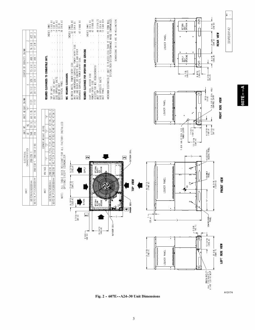
2. Remove horizontal (metal) ductcovers to access vertical(downflow) discharge duct knockouts in unit basepan. (SeeFig. 9.)
To remove downflow return and supply knockout covers, breakfront and right side connecting tabs with a screwdriver andhammer. Push cover down to break rear and left side tabs.
NOTE: These panels are held in place with tabs similar to anelectrical knockout. Reinstall horizontal duct covers (Fig. 9)shipped on unit from factory. Insure openings are air andwatertight.
NOTE: The design and installation of the duct system must be inaccordance with the standards of the NFPA for installation ofnonresidence--type air conditioning and ventilating systems, NFPA90A or residence--type, NFPA 90B; and/or local codes andordinances.
Adhere to the following criteria when selecting, sizing, andinstalling the duct system:
1. Units are shipped for side shot installation.2. Select and size ductwork, supply--air registers, and
return--air grilles according to American Society of Heating,Refrigeration and Air Conditioning Engineers (ASHRAE)recommendations.
3. Use flexible transition between rigid ductwork and unit toprevent transmission of vibration. The transition may bescrewed or bolted to duct flanges. Use suitable gaskets toensure weather--tight and airtight seal.
4. All units must have field--supplied filters or accessory filterrack installed in the return--air side of the unit.Recommended sizes for filters are shown in Table 1.
5. Size all ductwork for maximum required airflow (eitherheating or cooling) for unit being installed. Avoid abrupt
duct size increases or decreases or performance may beaffected.
6. Adequately insulate and weatherproof all ductwork locatedoutdoors. Insulate ducts passing through unconditionedspace, and use vapor barrier in accordance with latest issueof Sheet Metal and Air Conditioning Contractors NationalAssociation (SMACNA) and Air Conditioning Contractorsof America (ACCA) minimum installation standards forheating and air conditioning systems. Secure all ducts tobuilding structure.
7. Flash, weatherproof, and vibration--isolate all openings inbuilding structure in accordance with local codes and goodbuilding practices.
Horizontal Duct CoversA09076
BasepanDownflow(Vertical)SupplyKnockout
BasepanDownflow (Vertical)ReturnKnockout
A09093
Fig. 9 -- Supply and Return Duct Opening
607E----A

9
Step 8 — Install Electrical Connections
ELECTRICAL SHOCK HAZARD
Failure to follow this warning could result in personalinjury or death.
The unit cabinet must have an uninterrupted, unbrokenelectrical ground to minimize the possibility of personalinjury if an electrical fault should occur. This ground mayconsist of an electrical wire connected to the unit groundscrew in the control compartment, or conduit approved forelectrical ground when installed in accordance with NFPA70 (NEC) (latest edition) (in Canada, Canadian ElectricalCode CSA C22.1) and local electrical codes.
! WARNING
UNIT COMPONENT DAMAGE HAZARD
Failure to follow this caution may result in damage to theunit being installed.
1. Make all electrical connections in accordance withNFPA 70 (NEC) (latest edition) and local electrical codesgoverning such wiring. In Canada, all electricalconnections must be in accordance with CSA standardC22.1 Canadian Electrical Code Part 1 and applicablelocal codes. Refer to unit wiring diagram.
2. Use only copper conductor for connections betweenfield--supplied electrical disconnect switch and unit. DONOT USE ALUMINUM WIRE.
3. Be sure that high--voltage power to unit is withinoperating voltage range indicated on unit rating plate. On3--phase units, ensure phases are balanced within 2percent. Consult local power company for correction ofimproper voltage and/or phase imbalance.
4. Do not damage internal components when drillingthrough any panel to mount electrical hardware, conduit,etc.
! CAUTION
HIGH--VOLTAGE CONNECTIONSThe unit must have a separate electrical service with afield--supplied, waterproof disconnect switch mounted at, or withinsight from the unit. Refer to the unit rating plate, NEC and localcodes for maximum fuse/circuit breaker size and minimum circuitamps (ampacity) for wire sizing.
The field--supplied disconnect may be mounted on the unit overthe high--voltage inlet hole when the standard power andlow--voltage entry points are used. See Fig. 2 and 3 for acceptablelocation.
See unit wiring label (Fig. 15, 16 and 17) and Fig. 10 for referencewhen making high voltage connections. Proceed as follows tocomplete the high--voltage connections to the unit.
Single phase units:
1. Run the high--voltage (L1, L2) and ground lead into thecontrol box.
2. Connect ground lead to chassis ground connection.
3. Locate the black and yellow wires connected to the line sideof the contactor.
4. Connect field L1 to black wire from connection 11 of thecompressor contactor.
POWERSUPPLY
FIELD-SUPPLIEDFUSED DISCONNECT
HIGH VOLTAGEPOWER LEADS(SEE UNIT WIRINGLABEL)
EQUIP GR
CONTROL BOX
LOW-VOLTAGEPOWER LEADS(SEE UNITWIRING LABEL)
W2
Y1
G
R
C
WHT(W2)
YEL(Y1)
GRN(G)
RED(R)
BRN(C)
THERMOSTAT(TYPICAL)
3-PHASE SHOWN1-PHASE USES TWO POWER LEADS
W3VIO (W3)
SPLICE BOX
DHBLU (DH)
PINK (Y2)Y2
DH WIRE IS ON 208/230 VAC MODELSONLY.
OORN(O)
A13176
Fig. 10 -- High-- and Control--Voltage Connections
5. Connect field wire L2 to yellow wire from connection 23 ofthe compressor contactor.
Three--phase units:
1. Run the high--voltage (L1, L2, L3) and ground lead into thecontrol box.
2. Connect ground lead to chassis ground connection.
3. Locate the black and yellow wires connected to the line sideof the contactor.
4. Connect field L1 to black wire from connection 11 of thecompressor contactor.
5. Connect field wire L3 to yellow wire from connection 13 ofthe compressor contactor.
6. Connect field wire L2 to blue wire from compressor.
SPECIAL PROCEDURES FOR 208--V OPERATION
ELECTRICAL SHOCK HAZARD
Failure to follow this warning could result in personalinjury or death.
Before installing or servicing system, always turn off mainpower to system and install lockout tag. With disconnectswitch open, move black wire from transformer (3/16in.)(4.8 mm) terminal marked 230 to terminal marked 208.This retaps transformer to primary voltage of 208 vac.
! WARNING
CONTROL VOLTAGE CONNECTIONSNOTE: Do not use any type of power--stealing thermostat. Unitcontrol problems may result.
Use no. 18 American Wire Gage (AWG) color--coded, insulated(35C minimum) wires to make the control voltage connectionsbetween the thermostat and the unit. If the thermostat is locatedmore than 100 ft (30.5 m) from the unit (as measured along thecontrol voltage wires), use no. 16 AWG color--coded, insulated(35 C minimum) wires.
STANDARD CONNECTIONLocate the nine low voltage thermostat leads (eight for 460 VACmodels) in 24 volt splice box. See Fig. 10 for connection diagram.Run the low--voltage leads from the thermostat, through the controlwiring inlet hole grommet (Fig. 2 and 3), and into the low--voltagesplice box. Provide a drip loop before running wires through panel.Secure and strain relief all wires so that they do not interfere withoperation of unit.
607E----A

10
If an accessory electric heater is installed, low voltage leads fromheater must be connected to factory supplied control leads fromIndoor Fan Board P4 connector.
NOTE: If the unit 24V wires do not have a matching receptacle,cut the 24V wires from the electric heater plug, strip the ends, andwire nut together to match the schematic connections. If the electricheater 24V wires do not have a matching plug, cut the 24V wiresfrom the unit receptacle, strip the ends, and wire nut together tomatch the schematic connections.
Factory wires are provided for electric heat staging W1 and W2(W2 and W3 on IFB). If room thermostat has only one stage of
supplemental heat, connect white and violet wires shown in Fig. 10to second stage heat field wire.
Some electric heaters have four control wires (plus common wire).Consult unit wiring diagram and electric heater wiring diagram foradditional details.
TRANSFORMER PROTECTIONThe transformer is of the energy--limiting type, however a directshort will likely blow a secondary fuse. If an overload or short ispresent, correct overload condition and check for blower fuse onIndoor Fan Board. Replace fuse as required with correct size andrating.
Table 1 – Physical Data--Unit 607E----AUNIT SIZE 24 30 36 42 48 60NOMINAL CAPACITY (ton) 2 2---1/2 3 3---1/2 4 5SHIPPING WEIGHT lb.SHIPPING WEIGHT (kg)
356162
364165
420191
466212
462210
511232
COMPRESSORSQuantity
Scroll1
REFRIGERANT (R---410A)Quantity lbQuantity (kg)
9.04.1
10.04.5
11.05.0
14.66.6
12.05.4
14.86.7
REFRIGERANT METERING DEVICE TXV, Indoor TXVORIFICEOD (in.)OD (mm)
.032 (2)0.81 (2)
.040 (2)1.02 (2)
.042 (2)1.07 (2)
.042 (2)1.07 (2)
.042 (2)1.07 (2)
.052 (2)1.32 (2)
OUTDOOR COILRows...Fins/in.Face Area (sq ft)
2...2113.6
2...2115.3
2...2113.6
2...2119.4
2...2117.5
2...2123.3
OUTDOOR FANNominal CfmDiameter in.Diameter (mm)Motor Hp (Rpm)
210024609.6
1/12 (800)
250024609.61/8 (810)
300026660.41/5 (810)
300026660.41/5 (810)
330026660.41/5 (810)
360026660.41/5 (810)
INDOOR COILRows...Fins/in.Face Area (sq ft)
3...173.7
3...173.7
3...174.7
3...174.7
3...175.7
4...175.7
INDOOR BLOWERNominal Low Stage Cooling Airflow (Cfm)Nominal High Stage Cooling Airflow (Cfm)Size in.Size (mm.)Motor HP (RPM)
650 750 900 1050 1200 140065085010x10254x2541/2 (1050)
750100010x10254x2541/2 (1050)
900120011x10279.4x2543/4 (1000)
1050140011x10279.4x2543/4 (1075)
1200160011x10279.4x2541.0 (1075)
1400175011x10279.4x2541.0 (1075)
HIGH---PRESSURE SWITCH(psig) Cut---out Reset (Auto)
650 +/--- 15420 +/--- 25
LOW---PRESSURE SWITCH(psig) cut---out Reset (auto)
20 +/--- 545 +/--- 5
RETURN---AIR FILTERS†}Throwaway Size in.Throwaway Size (mm)
20x20x1508x508x25
20x24x1508x610x25
24x30x1610x762x25
24x36x1610x914x25
{ Required filter sizes shown are based on the larger of the AHRI (Air Conditioning Heating and Refrigeration Institute) rated cooling airflow or the heating air-flow velocity of 300 ft/minute for throwaway type or 450 ft/minute for high---capacity type. Air filter pressure drop for non---standard filters must not exceed 0.08in. W.C.} If using accessory filter rack refer to the filter rack installation instructionsfor correct filter sizes and quantity.
Table 2 – Minimum Airflow for Safe Electric Heater Operation (CFM)SIZE 24 30 36 42 48 60Cfm 850 1000 1200 1400 1600 1750
607E----A
11
PRE--START--UP
! WARNINGENVIRONMENTAL, FIRE, EXPLOSION,ELECTRICAL SHOCK HAZARD
Failure to follow this warning could result in personalinjury or death and/or property damage.
1. Follow recognized safety practices and wear protectivegoggles when checking or servicing refrigerant system.
2. Relieve and recover all refrigerant from system beforetouching or disturbing compressor plug if refrigerantleak is suspected around compressor terminals.
3. Never attempt to repair soldered connection whilerefrigerant system is under pressure.
4. Do not use torch to remove any component. Systemcontains oil and refrigerant under pressure.
5. To remove a component, wear protective goggles andproceed as follows:
a. Shut off electrical power to unit and installlockout tag.
b. Relieve and reclaim all refrigerant from systemusing both high-- and low--pressure ports.
c. Cut component connecting tubing with tubingcutter and remove component from unit.
d. Carefully unsweat remaining tubing stubs whennecessary. Oil can ignite when exposed to torchflame.
Use the Start--Up Checklist supplied at the end of this book andproceed as follows to inspect and prepare the unit for initialstart--up:
1. Remove all access panels (see Fig. 20).
2. Read and follow instructions on all DANGER, WARNING,CAUTION, and INFORMATION labels attached to, orshipped with unit.
3. Make the following inspections:
a. Inspect for shipping and handling damages, such asbroken lines, loose parts, disconnected wires, etc.
b. Inspect for oil at all refrigerant tubing connections andon unit base. Detecting oil generally indicates arefrigerant leak. Leak test all refrigerant tubingconnections using electronic leak detector, orliquid--soap solution. If a refrigerant leak is detected, seefollowing Check for Refrigerant Leaks section.
c. Inspect all field-- and factory--wiring connections. Besure that connections are completed and tight. Ensurewires do not touch refrigerant tubing or sharp sheetmetal edges.
d. Inspect coil fins. If damaged during shipping andhandling, carefully straighten fins with a fin comb.
4. Verify the following conditions:
a. Make sure that outdoor--fan blade is correctly positionedin fan orifice.
b. Make sure that air filter(s) is in place.
c. Make sure that condensate drain pan and trap are filledwith water to ensure proper drainage.
d. Make sure that all tools and miscellaneous loose partshave been removed
5. Each unit system has two (2) Schrader--type ports, one low--side Schrader fitting located on the suction line, and onehigh--side Schrader fitting located on the compressordischarge line. Be sure that caps on the ports are tight.
START--UPStep 1 — Check Cooling and Heating ControlOperationStart and check the unit for proper control operation as follows:
1. Place room thermostat SYSTEM switch or MODE controlin OFF position. Observe that blower motor starts whenFAN mode is placed in FAN ON position and shuts downwhen FAN MODE switch is placed in AUTO position.
2. Thermostat:On a typical two stage thermostat, when the room temper-ature rises 1 or 2 degrees above the cooling control settingof the thermostat, the thermostat completes the circuitbetween thermostat terminal R and terminals Y1, and G.These completed circuits through the thermostat connect thecontactor coil (C) (through unit wire Y1) and indoor fanboard (through unit wire G) across the 24--v. secondary oftransformer (TRAN).On a typical two stage thermostat, when the room temperat-ure is several degrees above the cooling control setting ofthe thermostat, the thermostat completes the circuit betweenterminal R and terminals Y1, Y2 , and G.
3. If your unit contains accessory electric heat, place systemswitch or MODE control in HEAT position. Set controlabove room temperature. Observe that the indoor blower isoperating and warm air is flowing through the supply airvents inside your home. Observe that the heating cycleshuts down when the control setting is satisfied.If your unit does not contain accessory electric heat and youwould like to obtain it, please contact your local dealer formore information.
4. When using an automatic changeover room thermostatplace both SYSTEM or MODE control and FAN modestitches in AUTO positions. Observe that unit operates inCooling mode when temperature control is set to “call forCooling” (below room temperature).
NOTE: Once the compressor has started and then has stopped, itshould not be started again until 5 minutes have elapsed.
Step 2 — Check for Refrigerant Leaks
EXPLOSION HAZARD
Failure to follow this warning couldresult in death, serious personal injury,and/or property damage.
Never use air or gases containingoxygen for leak testing or operatingrefrigerant compressors. Pressurizedmixtures of air or gases containingoxygen can lead to an explosion.
! WARNING
Proceed as follows to locate and repair a refrigerant leak and tocharge the unit:
1. Locate leak and make sure that refrigerant system pressurehas been relieved and reclaimed from both high--and low--pressure ports.
2. Repair leak following Refrigerant Service procedures.NOTE: Install a filter drier whenever the system has been openedfor repair.
3. Add a small charge of R--410A refrigerant vapor to systemand leak--test unit.
4. Recover refrigerant from refrigerant system and evacuate to500 microns if no additional leaks are found.
5. Charge unit with R--410A refrigerant, using an electronicscale. Refer to unit rating plate for required charge.
607E----A

12
Step 3 — Start--Up AdjustmentsComplete the required procedures given in the Pre--Start--Upsection before starting the unit. Do not jumper any safety deviceswhen operating the unit. Do not operate the unit in cooling modewhen the outdoor temperature is below 40_F (4_C) (unlessaccessory low--ambient kit is installed).
IMPORTANT: Three--phase, scroll compressors are directionoriented. Unit must be checked to ensure proper compressor3--phase power lead orientation. If not corrected within 5 minutes,the internal protector will shut off the compressor. The 3--phasepower leads to the unit must be reversd to correct rotation. Whenturning backwards, the difference between compressor suction anddischarge pressures may be near zero.
Checking and Adjusting Refrigerant Charge
EXPLOSION HAZARD
Failure to follow this warning couldresult in death, serious personal injury,and/or property damage.
Never use air or gases containingoxygen for leak testing or operatingrefrigerant compressors. Pressurizedmixtures of air or gases containingoxygen can lead to an explosion.
! WARNING
The refrigerant system is fully charged with R--410A refrigerantand is tested and factory sealed.
NOTE: Adjustment of the refrigerant charge is not requiredunless the unit is suspected of not having the proper R--410Acharge.
A subcooling charging chart is attached to the inside of thecompressor access panel. The chart includes the required liquid linetemperature at given discharge line pressures and outdoor ambienttemperatures.
An accurate thermocouple-- or thermistor--type thermometer, and agauge manifold are required when using the subcooling chargingmethod for evaluating the unit charge. Do not use mercury or smalldial--type thermometers because they are not adequate for this typeof measurement.
NOTE: Allow system to operate on high stage cooling for aminimum of 15 minutes before checking or adjusting refrigerantcharge.
IMPORTANT: When evaluating the refrigerant charge, anindicated adjustment to the specified factory charge must always bevery minimal. If a substantial adjustment is indicated, an abnormalcondition exists somewhere in the cooling system, such asinsufficient airflow across either coil or both coils.
1. Remove caps from low-- and high--pressure service fittings.2. Using hoses with valve core depressors, attach low-- and
high--pressure gauge hoses to low-- and high--pressureservice fittings, respectively.
3. Start unit and let run until system pressures stabilize.4. Measure and record the following:
a. Outdoor ambient--air temperature (F [C] db).b. Liquid line temperature (F [C]) at TXV.c. Discharge (high--side) pressure (psig).d. Suction (low--side) pressure (psig) (for reference
only).5. Using Cooling Charging Charts (See Fig. 18) compare
outdoor--air temperature (F [C] db) with the discharge linepressure (psig) to determine desired system operating liquidline temperature (See Fig. 18).
6. Compare actual liquid line temperature with desired liquidline temperature. Using a tolerance of 2F (1.1C), addrefrigerant if actual temperature is more than 2F (1.1C)higher than proper liquid line temperature, or removerefrigerant if actual temperature is more than 2F (1.1C)lower than required liquid line temperature.
NOTE: If the problem causing the inaccurate readings is arefrigerant leak, refer to Check for Refrigerant Leaks section.
Indoor Airflow and Airflow Adjustments
UNIT OPERATION HAZARD
Failure to follow this caution may result in unit damage.
For cooling operation, the recommended airflow is 350 to450 cfm for each 12,000 Btuh of rated cooling capacity. Forheating operation, the airflow must produce a temperaturerise that falls within the range stamped on the unit ratingplate.
! CAUTION
NOTE: Be sure that all supply--air and return--air grilles are open,free from obstructions, and adjusted properly.
ELECTRICAL SHOCK HAZARD
Failure to follow this warning could result in personalinjury or death.
Disconnect electrical power to the unit and install lockouttag before changing blower speed.
! WARNING
This unit has independent fan speeds for low stage cooling andhigh stage cooling. In addition, 208/230 VAC models have thefield--selectable capability to run an enhanced dehumidification(’DEHUM’) speed on high stage cooling (as low as 320 CFM perton). Coupled with the improved dehumidification associated withlow stage cooling, the DHUM speed allows for a completedehumidification solution independent of cooling stage. Table 3shows the operation modes and the associated fan speeds with eachmode:
Table 3 – Operation Modes and Fan Speeds
208/230 VAC Models
Operation Mode Fan Speed TapConnection
Low Stage Cooling/Heat Pump LOWHigh Stage Cooling/Heat Pump HIGH
High Stage EnhancedDehumidification Cooling
DH
Continuous Fan LOW
460 VAC Models
Operation Mode Fan Speed TapConnection
Low Stage Cooling/Heat Pump LOWHigh Stage Cooling/Heat Pump HIGH
Continuous Fan LOW
ELECTRICAL SHOCK HAZARD
Failure to follow this warning could result in personalinjury or death.
Disconnect electrical power to the unit and install lockouttag before changing blower speed.
! WARNING
607E----A

13
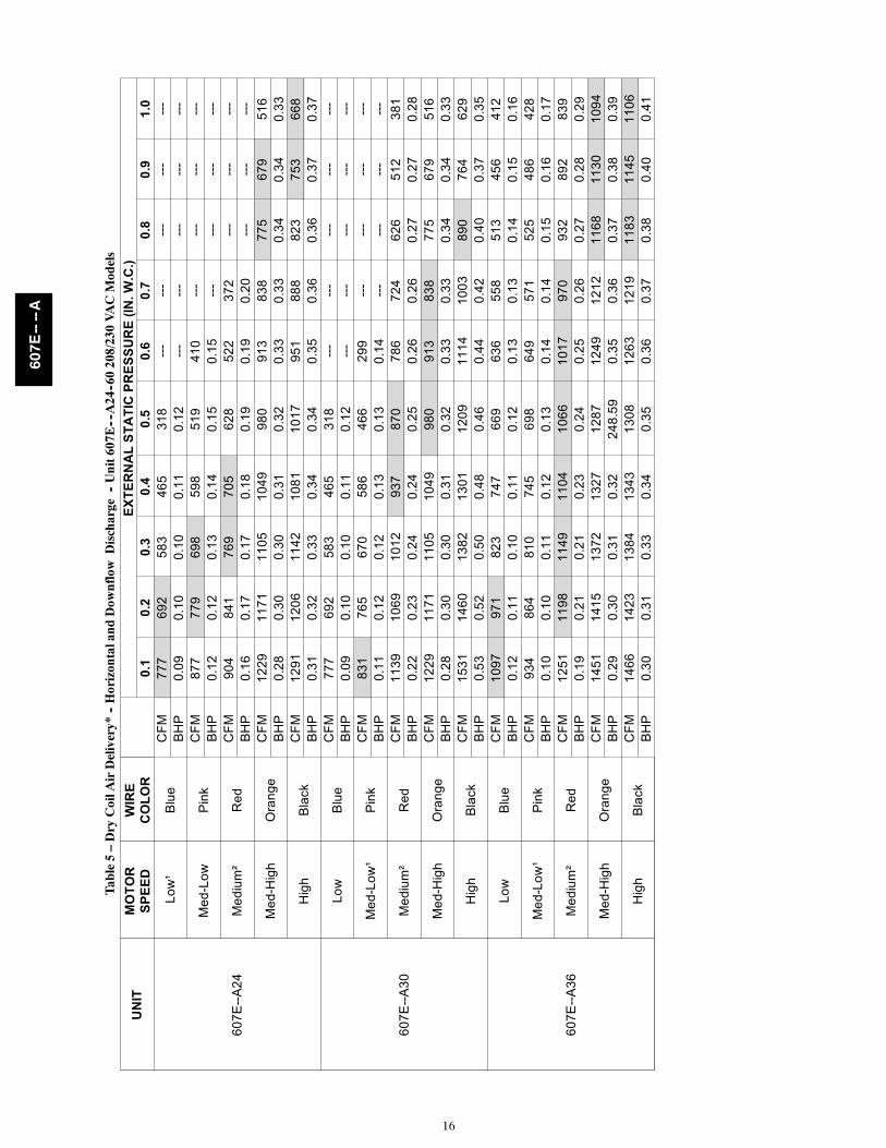
The evaporator fan motor is factory set to provide 5 different fanspeeds to choose from for the various operation modes (see Table4). All models are factory--shipped for nominal high stage and lowstage cooling airflow operation at minimum external staticpressure. See Table 2.
Table 4 – Color Coding for Indoor Fan Motor LeadsBlack = High Speed
Orange = Med--High SpeedRed = Med Speed
Pink = Med--Low SpeedBlue = Low Speed
Selection of Proper Fan Speeds for Operation Modes:
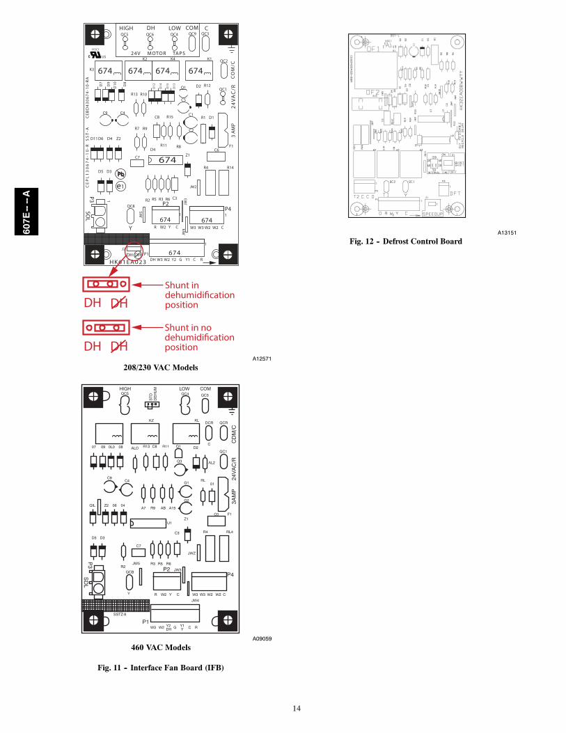
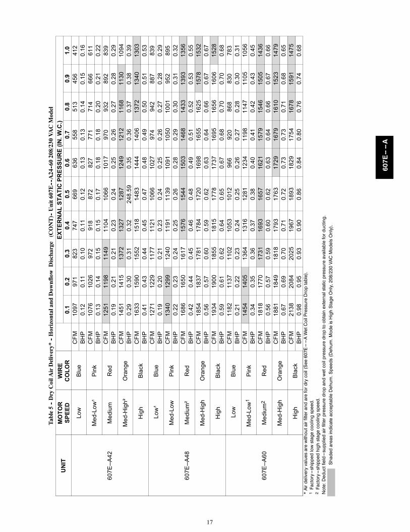
Low Stage Cooling/Heat Pump (All Models): Using Tables 7 , 8,and 9, find the external static pressure drops for wet coil,economizer, and filter, and add them to dry coil measured on thesystem. Using this total static pressure, look up Table 5 to find theairflows available at the total static pressure. For 208/230 VACmodels, connect the chosen fan speed wire to “LO COOL”connection on the IFB Board (see Fig. 11). For 460 VAC models,connect the chosen fan speed wire to “LOW” connection on theIFB (see Fig. 11).
High Stage Cooling/Heat Pump (All Models):Using Table 7 , 8,and 9, find the external static pressure drops for wet coil,economizer, and filter, and add them to dry coil measured on thesystem. Using this total static pressure, look up Table 5 to find theairflows available at the total static pressure. The speed chosenmust provide airflow of between 350 to 450 CFM per ton ofcooling. For 208/230 VAC models, connect the chosen fan speedwire to “HI COOL” connection on the IFB Board (See Fig. 11).For 460 VAC models, connect the chosen fan speed wire to“HIGH” connection on the IFB (see Fig. 11).
High Stage Enhanced Dehumidification Cooling (208/230 VACModels): Using the total static pressure for selecting the high stagecooling speed, look up Table 5 to find lower speed/airflowsavailable at that total static pressure. All airflows highlighted inTable 5 are acceptable for the Dehum speed. The speed chosenmust provide airflow of between 320 to 400 CFM per ton ofcooling. To activate the high stage enhanced dehumidificationcooling mode, the shunt jumper must be moved from the “No DH”to the “DH” selection. (See Fig. 11, close up.) For 208/230 VACmodels, connect the chosen fan speed wire to “DHUM” connectionon the IFB Board (see Fig. 11).
Continuous Fan (All Models): Continuous fan speed is the samespeed as Low Stage Cooling.
To activate the high stage enhanced dehumidification coolingmode, the shunt jumper in Fig. 11 must be moved from the No DHto DH selection (See Fig. 11, close up).
Using the Same Fan Speed for More than One Mode: Some fanspeeds are ideal for more than one mode of operation. It ispermissible to use a field--supplied jumper wire to connect onespeed tap wire to two or more speed connections on the InterfaceFan Board (IFB). Jumper wires must use 18 AWG wire with atleast 2/64” insulation.
SEQUENCE OF OPERATIONa. Continuous Fan
(1.) Thermostat closes circuit R to G energizing theblower motor for continuous fan. The indoor fan isenergized on low speed.
b. Cooling Mode
(1.) Low Stage: Thermostat closes R to G, R to Y1,and R to O. The compressor and indoor fan areenergized on low speed. The outdoor fan is alsoenergized
(2.) High Stage: Thermostat closes R to G, R to Y1, Rto Y2, and R to O. The compressor and indoor fanare energized on high speed. The outdoor fan isalso energized.
c. Electric Heating Mode
(1.) Thermostat closes circuit R to W2 or W3, and R toG. There are no on or off delays.
d. Heat Pump Heating
(1.) Low Stage: Thermostat closes R to G, R to Y1.The compressor and indoor fan are energized onlow speed. The outdoor fan is also energized
(2.) High Stage: Thermostat closes R to G, R to Y1, Rto Y2. The compressor and indoor fan are ener-gized on high speed. The outdoor fan is also ener-gized.
e. Heat Pump Heating with Auxiliary Heat(1.) Thermostat closes circuits R to G, R to Y and R to
W/W1 or W2. The compressor, indoor and outdoorfans are energized, as well as the electric heatrelays.
f. Defrost ModeThe defrost mode is automatically energized by thedefrost board during heating mode. The defrost boardenergizes “O” (reversing valve) and “W2” (electricheat). It also de--energizes the outdoor fan. When defrostis complete, unit will return to heating mode. If roomthermostat is satisfied during defrost, unit will shutdown and restart in defrost on next call for heat.
Step 4 — Defrost ControlQuiet ShiftQuiet Shift is a field--selectable defrost mode, which will eliminateoccasional noise that could be heard at the start of defrost cycle andrestarting of heating cycle. It is selected by placing DIP switch 3(on defrost board) in ON position.
When Quiet Shift switch is placed in ON position, and a defrost isinitiated, the following sequence of operation will occur. Reversingvalve will energize, outdoor fan will turn off, compressor will turnoff for 30 sec and then turn back on to complete defrost. At thestart of heating after conclusion of defrost reversing valve willde--energize, compressor will turn off for another 30 sec, and theoutdoor fan will stay off for 40 sec, before starting in the Heatingmode.
DefrostThe defrost control is a time/temperature control which includes afield--selectable time period (DIP switch 1 and 2 on the board)between defrost cycles of 30, 60, 90, or 120 minutes (factory set at60 minutes). To initiate a forced defrost, two options are availabledepending on the status of the defrost thermostat.
607E----A
14
PbPb
HIGH DH LOW COM
24V MOTOR TAPS
24VAC/R
COM/C
HK61EA023
674
P4P2
Y3
AM
P
C
P3SO
L
J2P1DH
DH W3 W2 Y2 G Y1 C R
1
DH
674 674W2 W2 W2W3 W3YR C C
11
JW4
JW3
JW5
R2 R5 R3 R6 C3
QC8
1
JW2
R4 R14D3D5
e1
C7 Z1
674
CE
PL
13
06
74
-10
-RS
ST
-AC
EB
D4
30
67
4-1
0-R
A
D11 D6 D4 Z2
D4R11 R8
R7 R9
C8 R15 C1
C2
R1 D1
R12D2Q1
C5
QC1R10R13
D12D10 D
8
D7
D9
D14
D15
D13
C9 C4
C6F1
674 674 674 674K3
K2 K4 K1 QC2
QC5 QC6 QC4 QC9 QC3
US
HSCI
DH
DH DH
DH
Shunt in no dehumidificationposition
Shunt in dehumidificationposition
A12571
208/230 VAC Models
HIGH LOW COMQC5 QC4 QC3
KZ KL
07 09 080L0 ALO R13 C8 R11 Q1
Q3
D2
AL2
DCR QCR
QC1
C
RL01G1
G2
Z1
A7 R9 AB A15
C4C9
C0
QIL Z2 06 04
U1
C3 R4 RL4
JWZ
C7
D5 D3
R3 R5 R6R2
JW5
QCB
Y R W2 Y C W3 W3 W2 W2 C
JW4
P2 JW3
P4
P1W2W3 Y2 Y1
YDH G C R
SSTZ-8
P3
SD
L
24V
AC
/R3A
MP
CD
M/C
F1
ST
DD
EH
UM
A09059
460 VAC Models
Fig. 11 -- Interface Fan Board (IFB)
A13151
Fig. 12 -- Defrost Control Board
607E----A

15
CO
MP
RE
SS
OR
AC
CU
MU
LATO
R
OUTDOOR COIL INDOOR COIL
LCS
LEGENDHPS – High Pressure SwitchLCS – Loss of Charge Switch
Accurater ® Metering De viceArrow indicates direction of flo w
Position
HP S
TXV in Bypass
Metering Position
C03012
Fig. 13 -- Typical Heat Pump Operation, Heating Mode
CO
MP
RE
SS
OR
AC
CU
MU
LATO
R
OUTDOOR COIL INDOOR COIL
LCS
LEGENDHPS – High Pressure SwitchLCS – Loss of Charge Switch
Accurater ® Metering De viceArrow indicates direction of flo w
TXV in Metering Position
BypassPosition
HP S
C03011
Fig. 14 -- Typical Heat Pump Operation, Cooling Mode
607E----A
16
Tab
le5
–D
ryC
oilA
irD
eliv
ery*
--H
oriz
onta
land
Dow
nflo
wD
isch
arge
--U
nit6
07E
----A
24--6
020
8/23
0V
AC
Mod
els
UN
ITM
OT
OR
SP
EE
DW
IRE
CO
LO
RE
XT
ER
NA
LS
TA
TIC
PR
ES
SU
RE
(IN
.W.C
.)0
.10
.20
.30
.40
.50
.60
.70
.80
.91
.0
60
7E
--A
24
Lo
w¹
Blu
eC
FM
77
76
92
58
34
65
31
8--
---
---
---
---
-B
HP
0.0
90
.10
0.1
00
.11
0.1
2--
---
---
---
---
-
Me
d-L
ow
Pin
kC
FM
87
77
79
69
85
98
51
94
10
---
---
---
---
BH
P0
.12
0.1
20
.13
0.1
40
.15
0.1
5--
---
---
---
-
Me
diu
m²
Re
dC
FM
90
48
41
76
97
05
62
85
22
37
2--
---
---
-B
HP
0.1
60
.17
0.1
70
.18
0.1
90
.19
0.2
0--
---
---
-
Me
d-H
igh
Ora
ng
eC
FM
12
29
11
71
11
05
10
49
98
09
13
83
87
75
67
95
16
BH
P0
.28
0.3
00
.30
0.3
10
.32
0.3
30
.33
0.3
40
.34
0.3
3
Hig
hB
lack
CF
M1
29
11
20
61
14
21
08
11
01
79
51
88
88
23
75
36
68
BH
P0
.31
0.3
20
.33
0.3
40
.34
0.3
50
.36
0.3
60
.37
0.3
7
60
7E
--A
30
Lo
wB
lue
CF
M7
77
69
25
83
46
53
18
---
---
---
---
---
BH
P0
.09
0.1
00
.10
0.1
10
.12
---
---
---
---
---
Me
d-L
ow
¹P
ink
CF
M8
31
76
56
70
58
64
66
29
9--
---
---
---
-B
HP
0.1
10
.12
0.1
20
.13
0.1
30
.14
---
---
---
---
Me
diu
m²
Re
dC
FM
11
39
10
69
10
12
93
78
70
78
67
24
62
65
12
38
1B
HP
0.2
20
.23
0.2
40
.24
0.2
50
.26
0.2
60
.27
0.2
70
.28
Me
d-H
igh
Ora
ng
eC
FM
12
29
11
71
11
05
10
49
98
09
13
83
87
75
67
95
16
BH
P0
.28
0.3
00
.30
0.3
10
.32
0.3
30
.33
0.3
40
.34
0.3
3
Hig
hB
lack
CF
M1
53
11
46
01
38
21
30
11
20
91
11
41
00
38
90
76
46
29
BH
P0
.53
0.5
20
.50
0.4
80
.46
0.4
40
.42
0.4
00
.37
0.3
5
60
7E
--A
36
Lo
wB
lue
CF
M1
09
79
71
82
37
47
66
96
36
55
85
13
45
64
12
BH
P0
.12
0.1
10
.10
0.1
10
.12
0.1
30
.13
0.1
40
.15
0.1
6
Me
d-L
ow
¹P
ink
CF
M9
34
86
48
10
74
56
98
64
95
71
52
54
86
42
8B
HP
0.1
00
.10
0.1
10
.12
0.1
30
.14
0.1
40
.15
0.1
60
.17
Me
diu
m²
Re
dC
FM
12
51
11
98
11
49
11
04
10
66
10
17
97
09
32
89
28
39
BH
P0
.19
0.2
10
.21
0.2
30
.24
0.2
50
.26
0.2
70
.28
0.2
9
Me
d-H
igh
Ora
ng
eC
FM
14
51
14
15
13
72
13
27
12
87
12
49
12
12
11
68
11
30
10
94
BH
P0
.29
0.3
00
.31
0.3
22
48
.59
0.3
50
.36
0.3
70
.38
0.3
9
Hig
hB
lack
CF
M1
46
61
42
31
38
41
34
31
30
81
26
31
21
91
18
31
14
51
10
6B
HP
0.3
00
.31
0.3
30
.34
0.3
50
.36
0.3
70
.38
0.4
00
.41
607E----A
17
Tab
le5
--D
ryC
oilA
irD
eliv
ery*
--H
oriz
onta
land
Dow
nflo
wD
isch
arge
(CO
NT
)--U
nit6
07E
----A
24--6
020
8/23
0V
AC
Mod
el
UN
ITM
OT
OR
SP
EE
DW
IRE
CO
LO
RE
XT
ER
NA
LS
TA
TIC
PR
ES
SU
RE
(IN
.W.C
.)0
.10
.20
.30
.40
.50
.60
.70
.80
.91
.0
60
7E
--A
42
Lo
wB
lue
CF
M1
09
79
71
82
37
47
66
96
36
55
85
13
45
64
12
BH
P0
.12
0.1
10
.10
0.1
10
.12
0.1
30
.13
0.1
40
.15
0.1
6
Me
d-L
ow
¹P
ink
CF
M1
07
61
02
69
72
91
88
72
82
77
71
71
46
66
61
1B
HP
0.1
30
.14
0.1
50
.15
0.1
70
.18
0.1
80
.20
0.2
10
.22
Me
diu
mR
ed
CF
M1
25
11
19
81
14
91
10
41
06
61
01
79
70
93
28
92
83
9B
HP
0.1
90
.21
0.2
10
.23
0.2
40
.25
0.2
60
.27
0.2
80
.29
Me
d-H
igh
²O
ran
ge
CF
M1
45
11
41
51
37
21
32
71
28
71
24
91
21
21
16
81
13
01
09
4B
HP
0.2
90
.30
0.3
10
.32
24
8.5
90
.35
0.3
60
.37
0.3
80
.39
Hig
hB
lack
CF
M1
63
31
59
01
55
21
51
81
48
31
44
41
40
61
37
21
34
01
30
3B
HP
0.4
10
.43
0.4
40
.45
0.4
70
.48
0.4
90
.50
0.5
10
.53
60
7E
--A
48
Lo
w¹
Blu
eC
FM
12
71
12
29
11
77
11
21
10
66
10
27
97
49
42
88
78
39
BH
P0
.19
0.2
00
.21
0.2
30
.24
0.2
50
.26
0.2
70
.28
0.2
9
Me
d-L
ow
Pin
kC
FM
13
40
12
99
12
40
11
91
11
39
10
91
10
50
10
01
95
28
95
BH
P0
.22
0.2
30
.24
0.2
50
.26
0.2
80
.29
0.3
00
.31
0.3
2
Me
diu
m²
Re
dC
FM
16
86
16
50
16
17
15
76
15
44
15
03
14
68
14
33
13
93
13
56
BH
P0
.42
0.4
40
.45
0.4
60
.48
0.4
90
.51
0.5
20
.53
0.5
5
Me
d-H
igh
Ora
ng
eC
FM
18
54
18
37
17
81
17
84
17
20
16
98
16
55
16
25
15
78
15
32
BH
P0
.56
0.5
70
.60
0.5
90
.62
0.6
30
.64
0.6
60
.67
0.6
7
Hig
hB
lack
CF
M1
93
41
90
01
85
51
81
51
77
81
73
71
69
51
65
61
60
61
52
8B
HP
0.5
90
.61
0.6
20
.64
0.6
50
.67
0.6
80
.70
0.7
00
.68
60
7E
--A
60
Lo
wB
lue
CF
M1
18
21
13
71
10
21
05
31
01
29
66
92
08
68
83
07
83
BH
P0
.21
0.2
20
.23
0.2
40
.25
0.2
60
.27
0.2
80
.30
0.3
1
Me
d-L
ow
1P
ink
CF
M1
45
41
40
51
36
41
31
61
28
11
23
41
19
81
14
71
10
51
05
6B
HP
0.3
40
.35
0.3
60
.37
0.3
80
.40
0.4
10
.42
0.4
30
.45
Me
diu
m2
Re
dC
FM
18
18
17
70
17
31
16
93
16
57
16
21
15
79
15
46
15
05
14
36
BH
P0
.56
0.5
70
.59
0.6
00
.62
0.6
30
.64
0.6
60
.67
0.6
6
Me
d-H
igh
Ora
ng
eC
FM
18
81
18
49
18
18
17
93
17
63
17
29
16
79
16
10
15
23
14
79
BH
P0
.67
0.6
90
.70
0.7
10
.72
0.7
30
.73
0.7
10
.68
0.6
5
Hig
hB
lack
CF
M2
13
82
08
42
02
51
96
71
89
31
82
91
75
41
67
81
59
11
47
5B
HP
0.9
80
.95
0.9
30
.90
0.8
60
.84
0.8
00
.76
0.7
40
.68
*Airdeliveryvaluesarewithoutairfilterandarefordrycoil(See607E------AWetCoilPressureDroptable).
1Factory---shippedlowstagecoolingspeed.
2Factory---shippedhighstagecoolingspeed.
Note:Deductfield---suppliedairfilterpressuredropandwetcoilpressuredroptoobtainexternalstaticpressureavailableforducting.
ShadedareasindicateacceptableDehum.Speeds(Dehum.ModeisHighStageOnly,208/230VACModelsOnly).
607E----A

18
Tab
le6
–D
ryC
oilA
irD
eliv
ery*
--H
oriz
onta
land
Dow
nflo
wD
isch
arge
--U
nit6
07E
----A
24--6
046
0VA
CM
odel
s
UN
ITM
OTO
RSP
EED
WIR
EC
OLO
REX
TER
NA
LST
ATI
CP
RES
SUR
E(I
N.W
.C.)
0.1
0.2
0.3
0.4
0.5
0.6
0.7
0.8
0.9
1.0
60
7E
--A
36
Lo
w1
Blu
eC
FM
93
48
64
81
07
45
69
86
49
57
15
25
48
64
28
BH
P0
.10
0.1
00
.11
0.1
20
.13
0.1
40
.14
0.1
50
.16
0.1
7
Me
d-L
ow
Pin
kC
FM
10
76
10
26
97
29
18
87
28
27
77
17
14
66
66
11
BH
P0
.13
0.1
40
.15
0.1
50
.17
0.1
80
.18
0.2
00
.21
0.2
2
Me
diu
mR
ed
CF
M1
21
31
16
91
11
01
06
51
01
69
64
92
38
78
82
07
77
BH
P0
.16
0.1
70
.17
0.1
90
.20
0.2
10
.22
0.2
30
.24
0.2
5
Me
d-H
igh
2O
ran
ge
CF
M1
25
11
19
81
14
91
10
41
06
61
01
79
70
93
28
92
83
9B
HP
0.1
90
.21
0.2
10
.23
0.2
40
.25
0.2
60
.27
0.2
80
.29
Hig
hB
lack
CF
M1
45
11
41
51
37
21
32
71
28
71
24
91
21
21
16
81
13
01
09
4B
HP
0.2
90
.30
0.3
10
.32
24
8.5
90
.35
0.3
60
.37
0.3
80
.39
60
7E
--A
42
Lo
w1
Blu
eC
FM
10
76
10
26
97
29
18
87
28
27
77
17
14
66
66
11
BH
P0
.13
0.1
40
.15
0.1
50
.17
0.1
80
.18
0.2
00
.21
0.2
2
Me
d-L
ow
Pin
kC
FM
12
13
11
69
11
10
10
65
10
16
96
49
23
87
88
20
77
7B
HP
0.1
60
.17
0.1
70
.19
0.2
00
.21
0.2
20
.23
0.2
40
.25
Me
diu
mR
ed
CF
M1
25
11
19
81
14
91
10
41
06
61
01
79
70
93
28
92
83
9B
HP
0.1
90
.21
0.2
10
.23
0.2
40
.25
0.2
60
.27
0.2
80
.29
Me
d-H
igh
²O
ran
ge
CF
M1
45
11
41
51
37
21
32
71
28
71
24
91
21
21
16
81
13
01
09
4B
HP
0.2
90
.30
0.3
10
.32
24
8.5
90
.35
0.3
60
.37
0.3
80
.39
Hig
hB
lack
CF
M1
63
31
59
01
55
21
51
81
48
31
44
41
40
61
37
21
34
01
30
3B
HP
0.4
10
.43
0.4
40
.45
0.4
70
.48
0.4
90
.50
0.5
10
.53
60
7E
--A
48
Lo
w¹
Blu
eC
FM
12
71
12
29
11
77
11
21
10
66
10
27
97
49
42
88
78
39
BH
P0
.19
0.2
00
.21
0.2
30
.24
0.2
50
.26
0.2
70
.28
0.2
9
Me
d-L
ow
Pin
kC
FM
13
40
12
99
12
40
11
91
11
39
10
91
10
50
10
01
95
28
95
BH
P0
.22
0.2
30
.24
0.2
50
.26
0.2
80
.29
0.3
00
.31
0.3
2
Me
diu
m²
Re
dC
FM
16
86
16
50
16
17
15
76
15
44
15
03
14
68
14
33
13
93
13
56
BH
P0
.42
0.4
40
.45
0.4
60
.48
0.4
90
.51
0.5
20
.53
0.5
5
Me
d-H
igh
Ora
ng
eC
FM
18
54
18
37
17
81
17
84
17
20
16
98
16
55
16
25
15
78
15
32
BH
P0
.56
0.5
70
.60
0.5
90
.62
0.6
30
.64
0.6
60
.67
0.6
7
Hig
hB
lack
CF
M2
13
12
08
82
06
52
01
31
98
21
94
11
88
81
86
01
78
51
75
1B
HP
0.7
20
.74
0.7
50
.77
0.7
90
.80
0.8
10
.81
0.7
90
.75
607E----A
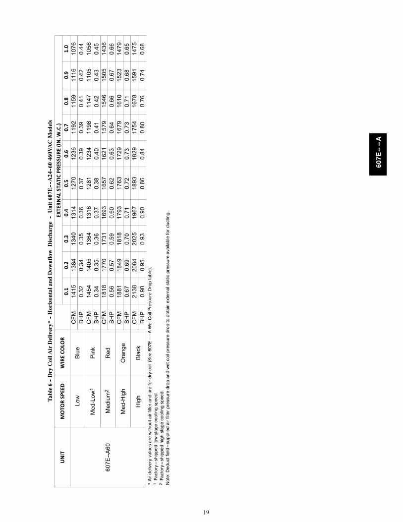
19
Tab
le6
--D
ryC
oilA
irD
eliv
ery*
--H
oriz
onta
land
Dow
nflo
wD
isch
arge
--U
nit6
07E
----A
24--6
046
0VA
CM
odel
s
UN
ITM
OTO
RSP
EED
WIR
EC
OLO
REX
TER
NA
LST
ATI
CP
RES
SUR
E(I
N.W
.C.)
0.1
0.2
0.3
0.4
0.5
0.6
0.7
0.8
0.9
1.0
60
7E
--A
60
Lo
wB
lue
CF
M1
41
51
38
41
34
01
31
41
27
01
23
61
19
21
15
91
11
61
07
6B
HP
0.3
20
.34
0.3
50
.36
0.3
70
.39
0.3
90
.41
0.4
20
.44
Me
d-L
ow
1P
ink
CF
M1
45
41
40
51
36
41
31
61
28
11
23
41
19
81
14
71
10
51
05
6B
HP
0.3
40
.35
0.3
60
.37
0.3
80
.40
0.4
10
.42
0.4
30
.45
Me
diu
m2
Re
dC
FM
18
18
17
70
17
31
16
93
16
57
16
21
15
79
15
46
15
05
14
36
BH
P0
.56
0.5
70
.59
0.6
00
.62
0.6
30
.64
0.6
60
.67
0.6
6
Me
d-H
igh
Ora
ng
eC
FM
18
81
18
49
18
18
17
93
17
63
17
29
16
79
16
10
15
23
14
79
BH
P0
.67
0.6
90
.70
0.7
10
.72
0.7
30
.73
0.7
10
.68
0.6
5
Hig
hB
lack
CF
M2
13
82
08
42
02
51
96
71
89
31
82
91
75
41
67
81
59
11
47
5B
HP
0.9
80
.95
0.9
30
.90
0.8
60
.84
0.8
00
.76
0.7
40
.68
*Airdeliveryvaluesarewithoutairfilterandarefordrycoil(See607E------AWetCoilPressureDroptable).
1Factory---shippedlowstagecoolingspeed.
2Factory---shippedhighstagecoolingspeed.
Note:Deductfield---suppliedairfilterpressuredropandwetcoilpressuredroptoobtainexternalstaticpressureavailableforducting.
607E----A

20
Tab
le7
–W
etC
oilP
ress
ure
Dro
p(I
N.W
.C.)
UN
ITS
IZE
STA
ND
AR
DC
FM
(SC
FM
)60
070
080
090
010
0011
0012
0013
0014
0015
0016
0017
0018
0019
0020
0021
0022
0024
0.03
0.04
0.05
0.06
0.07
300.
060.
070.
070.
080.
0936
0.06
0.07
0.08
0.09
0.10
0.11
420.
070.
080.
090.
100.
110.
110.
120.
1248
0.03
0.04
0.08
0.08
0.10
0.11
0.14
0.15
0.16
600.
080.
100.
110.
140.
150.
160.
16
Tab
le8
–E
cono
miz
erw
ith
1--i
n.F
ilter
Pre
ssur
eD
rop
(IN
.W.C
.)
FIL
TE
RS
IZE
IN.(
MM
)C
OO
LIN
GTO
NS
STA
ND
AR
DC
FM
(SC
FM
)60
070
080
090
010
0011
0012
0013
0014
0015
0016
0017
0018
0019
0020
0021
0022
0060
0--1
400C
FM
12x2
0x1+
12x2
0x1
(305
x508
x25+
305x
508x
25)
2.0,
2.5
----
0.09
0.14
0.16
0.18
0.25
0.28
0.3
----
----
----
----
1200
--180
0C
FM
16x2
4x1+
14x2
4x1
(406
x610
x25+
356x
610x
25)
3.0,
3.5
----
----
----
0.10
0.11
0.12
0.13
0.14
0.16
0.16
----
----
1500
--220
0C
FM
16x2
4x1+
18x2
4x1
(406
x610
x25+
457x
610x
25)
4.0
5.0
----
----
----
----
--0.
150.
170.
180.
200.
210.
220.
230.
23
Tab
le9
–F
ilter
Pre
ssur
eD
rop
Tab
le(I
N.W
.C.)
FIL
TE
RS
IZE
IN.(
MM
)C
OO
LIN
GTO
NS
STA
ND
AR
DC
FM
(SC
FM
)60
070
080
090
010
0011
0012
0013
0014
0015
0016
0017
0018
0019
0020
0021
0022
0060
0--1
400C
FM
12x2
0x1+
12x2
0x1
(305
x508
x25+
305x
508x
25
2.0,
2.5
0.03
0.05
0.06
0.08
0.10
0.11
0.13
0.14
0.16
----
----
----
----
1200
--180
0C
FM
16x2
4x1+
14x2
4x1
(406
x610
x25+
356x
610x
25)
3.0,
3.5
----
----
----
0.07
0.08
0.09
0.09
0.10
0.11
0.12
----
----
1500
--220
0C
FM
16x2
4x1+
18x2
4x1
(406
x610
x25+
457x
610x
25)
4.0
5.0
----
----
----
----
--0.
040.
060.
080.
100.
110.
130.
140.
15
607E----A

21
Tab
le10
–E
lect
ric
Hea
tPre
ssur
eD
rop
Tab
les
(IN
.W.C
.)Sm
allC
abin
et:2
4--3
0
STA
TIC
STA
ND
AR
DC
FM
(SC
FM
)50
060
070
080
090
010
0011
0012
0013
0014
0015
0016
005
kW0.
000.
000.
000.
000.
000.
000.
000.
000.
020.
040.
060.
07
10kW
0.00
0.00
0.00
0.00
0.00
0.02
0.04
0.06
0.07
0.09
0.10
0.11
15kW
0.00
0.00
0.00
0.02
0.04
0.06
0.08
0.10
0.12
0.14
0.16
0.18
20kW
0.00
0.00
0.02
0.04
0.06
0.08
0.09
0.11
0.13
0.15
0.17
0.19
Lar
geC
abin
et:3
6--6
0
STA
TIC
STA
ND
AR
DC
FM
(SC
FM
)11
0012
0013
0014
0015
0016
0017
0018
0019
0020
0021
0022
0023
0024
0025
005
kW0.
000.
000.
000.
010.
020.
030.
040.
050.
060.
070.
080.
090.
100.
110.
12
10kW
0.00
0.00
0.01
0.02
0.03
0.04
0.05
0.06
0.07
0.08
0.09
0.10
0.11
0.12
0.13
15kW
0.00
0.02
0.03
0.04
0.05
0.06
0.07
0.08
0.09
0.10
0.11
0.12
0.13
0.14
0.15
20kW
0.02
0.03
0.04
0.05
0.06
0.07
0.08
0.09
0.10
0.11
0.12
0.13
0.14
0.15
0.16
607E----A
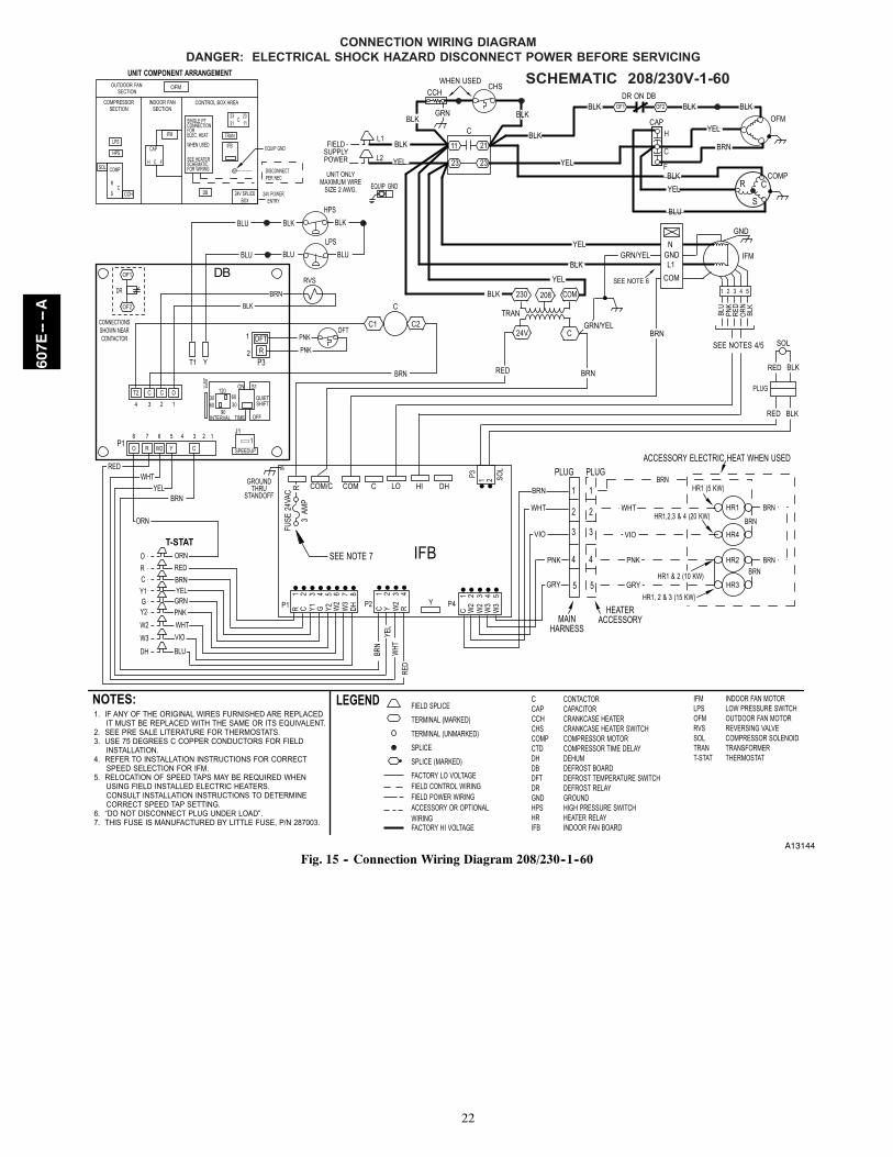
22
A13144
Fig. 15 -- Connection Wiring Diagram 208/230--1--60
607E----A

23
A13145
Fig. 12 Cont. -- Ladder Wiring Diagram 208/230--1--60
607E----A

24
A13146
Fig. 16 -- Connection Wiring Diagram 208/230--3--60
607E----A
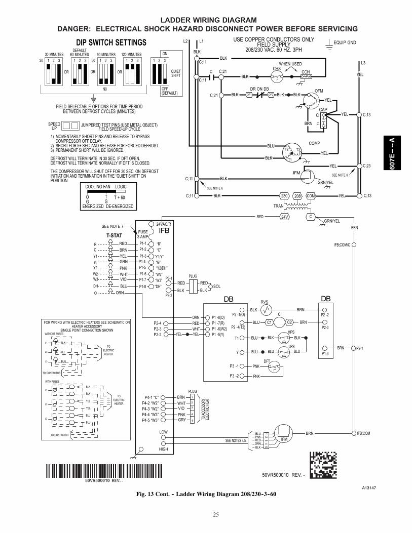
25
A13147
Fig. 13 Cont. -- Ladder Wiring Diagram 208/230--3--60
607E----A

26
A13148
Fig. 17 -- Connection Wiring Diagram 460--3--60
607E----A
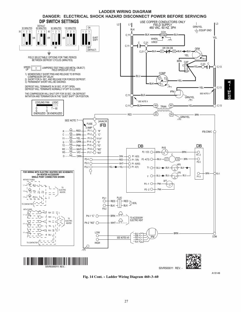
27
A13149
Fig. 14 Cont. -- Ladder Wiring Diagram 460--3--60
607E----A
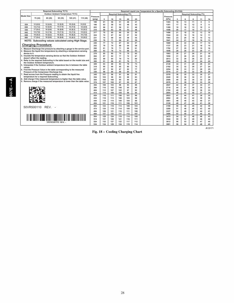
28
A13171
Fig. 18 -- Cooling Charging Chart
607E----A

29
MAINTENANCETo ensure continuing high performance, and to minimize thepossibility of premature equipment failure, periodic maintenancemust be performed on this equipment. This cooling unit should beinspected at least once each year by a qualified service person. Totroubleshoot unit, refer to Table 11, Troubleshooting Chart.
NOTE TO EQUIPMENT OWNER: Consult your local dealerabout the availability of a maintenance contract.
PERSONAL INJURY AND UNIT DAMAGEHAZARD
Failure to follow this warning could result in personalinjury or death and possible unit component damage.
The ability to properly perform maintenance on thisequipment requires certain expertise, mechanical skills,tools and equipment. If you do not possess these, do notattempt to perform any maintenance on this equipment,other than those procedures recommended in the Owner’sManual.
! WARNING
ELECTRICAL SHOCK AND FIRE HAZARD
Failure to follow these warnings could result in personalinjury or death:
1. Turn off electrical power to the unit and install lockouttag before performing any maintenance or service on thisunit.
2. Use extreme caution when removing panels and parts.
3. Never place anything combustible either on or in contactwith the unit.
! WARNING
UNIT OPERATION HAZARD
Failure to follow this caution may result in equipmentdamage or improper operation.
Errors made when reconnecting wires may cause improperand dangerous operation. Label all wires prior todisconnecting when servicing.
CAUTION!
The minimum maintenance requirements for this equipment are asfollows:
1. Inspect air filter(s) each month. Clean or replace whennecessary.
2. Inspect indoor coil, drain pan, and condensate drain eachcooling season for cleanliness. Clean when necessary.
3. Inspect blower motor and wheel for cleanliness eachcooling season. Clean when necessary.
4. Check electrical connections for tightness and controls forproper operation each cooling season. Service whennecessary.
5. Ensure electric wires are not in contact with refrigeranttubing or sharp metal edges.
Air FilterIMPORTANT: Never operate the unit without a suitable air filterin the return--air duct system. Always replace the filter with thesame dimensional size and type as originally installed. See Table 1for recommended filter sizes.
Inspect air filter(s) at least once each month and replace(throwaway--type) or clean (cleanable--type) at least twice duringeach cooling season and twice during the heating season, orwhenever the filter becomes clogged with dust and lint.
Indoor Blower and MotorNOTE: All motors are pre--lubricated. Do not attempt to lubricatethese motors.
For longer life, operating economy, and continuing efficiency,clean accumulated dirt and grease from the blower wheel andmotor annually.
ELECTRICAL SHOCK HAZARD
Failure to follow this warning could result in personalinjury or death.
Disconnect and tag electrical power to the unit beforecleaning the blower motor and wheel.
! WARNING
To clean the blower motor and wheel:
1. Remove and disassemble blower assembly as follows:
a. Remove blower access panel (see Fig. 20).
b. Disconnect 5 pin plug and 4 pin plug from indoorblower motor. Remove capacitor if required.
c. On all units remove blower assembly from unit.Remove screws securing blower to blower partition andslide assembly out. Be careful not to tear insulation inblower compartment.
d. Ensure proper reassembly by marking blower wheel andmotor in relation to blower housing before disassembly.
e. Loosen setscrew(s) that secures wheel to motor shaft,remove screws that secure motor mount brackets tohousing, and slide motor and motor mount out ofhousing.
2. Remove and clean blower wheel as follows:
a. Ensure proper reassembly by marking wheel orientation.
b. Lift wheel from housing. When handling and/orcleaning blower wheel, be sure not to disturb balanceweights (clips) on blower wheel vanes.
c. Remove caked--on dirt from wheel and housing with abrush. Remove lint and/or dirt accumulations fromwheel and housing with vacuum cleaner, using softbrush attachment. Remove grease and oil with mildsolvent.
d. Reassemble wheel into housing.
e. Reassemble motor into housing. Be sure setscrews aretightened on motor shaft flats and not on round part ofshaft. Reinstall blower into unit.
f. Connect 5 pin plug and 4 pin plug to indoor blowermotor. Reinstall capacitor if required.
g. Reinstall blower access panel (see Fig. 20).
3. Restore electrical power to unit. Start unit and check forproper blower rotation and motor speeds during coolingcycles.
607E----A

30
MOTOR FAN GRILLE
MOTOR SHAFT
A
A08505
MAX DISTANCE BETWEEN TOP OF FAN GRILLE AND BOTTOM OF FAN BLADE
SIZE“A”
IN. MM24 6.3 16030 6.3 16036 7.6 19342 7.6 19348 7.6 19360 7.6 193
Fig. 19 -- Fan Blade Position
Compressor Access Panel
BlowerAccessPanel
ControlAccessPanel
A09214
Fig. 20 -- Unit Access PanelsOutdoor Coil, Indoor Coil, and Condensate Drain PanInspect the condenser coil, evaporator coil, and condensate drainpan at least once each year.
The coils are easily cleaned when dry; therefore, inspect and cleanthe coils either before or after each cooling season. Remove allobstructions, including weeds and shrubs, that interfere with theairflow through the condenser coil.
Straighten bent fins with a fin comb. If coated with dirt or lint,clean the coils with a vacuum cleaner, using the soft brushattachment. Be careful not to bend the fins. If coated with oil orgrease, clean the coils with a mild detergent and water solution.Rinse coils with clear water, using a garden hose. Be careful not tosplash water on motors, insulation, wiring, or air filter(s). For bestresults, spray condenser coil fins from inside to outside the unit. Onunits with an outer and inner condenser coil, be sure to cleanbetween the coils. Be sure to flush all dirt and debris from the unitbase.
Inspect the drain pan and condensate drain line when inspectingthe coils. Clean the drain pan and condensate drain by removing allforeign matter from the pan. Flush the pan and drain trough withclear water. Do not splash water on the insulation, motor, wiring, orair filter(s). If the drain trough is restricted, clear it with a“plumbers snake” or similar probe device.
OUTDOOR FAN
UNIT OPERATION HAZARD
Failure to follow this caution may result in damage to unitcomponents.
Keep the condenser fan free from all obstructions to ensureproper cooling operation. Never place articles on top of theunit.
CAUTION!
1. Remove 6 screws holding condenser grille and motor to topcover.
2. Turn motor/grille assembly upside down on top cover toexpose the fan blade.
3. Inspect the fan blades for cracks or bends.
4. If fan needs to be removed, loosen the setscrew and slide thefan off the motor shaft.
5. When replacing fan blade, position blade as shown in Fig.19.
6. Ensure that setscrew engages the flat area on the motor shaftwhen tightening
7. Replace grille.
Electrical Controls and WiringInspect and check the electrical controls and wiring annually. Besure to turn off the electrical power to the unit.
Remove access panels (see Fig. 20) to locate all the electricalcontrols and wiring. Check all electrical connections for tightness.Tighten all screw connections. If any smoky or burned connectionsare noticed, disassemble the connection, clean all the parts, restripthe wire end and reassemble the connection properly and securely.
607E----A
31
After inspecting the electrical controls and wiring, replace theaccess panels (see Fig. 20). Start the unit, and observe at least onecomplete heating cycle and one complete cooling cycle to ensureproper operation. If discrepancies are observed in either or bothoperating cycles, or if a suspected malfunction has occurred, checkeach electrical component with the proper electricalinstrumentation. Refer to the unit wiring label when making thesecheckouts.
NOTE: Refer to the heating and/or cooling sequence of operationin this publication as an aid in determining proper controloperation
Refrigerant CircuitInspect all refrigerant tubing connections and the unit base for oilaccumulations annually. Detecting oil generally indicates arefrigerant leak.
EXPLOSION, SAFETY AND ENVIRONMENTALHAZARD
Failure to follow this warning could result in personalinjury, death or equipment damage.
This system uses Puron (R--410A) refrigerant which hashigher operating pressures than R--22 and other refrigerants.No other refrigerant may be used in this system. Gauge set,hoses, and recovery system must be designed to handlePuron. If you are unsure, consult the equipmentmanufacturer.
WARNING!
If oil is detected or if low cooling performance is suspected,leak--test all refrigerant tubing using an electronic leak--detector,halide torch, or liquid--soap solution. If a refrigerant leak isdetected, refer to Check for Refrigerant Leaks section.
If no refrigerant leaks are found and low cooling performance issuspected, refer to Checking and Adjusting Refrigerant Chargesection.
Evaporator AirflowThe heating and/or cooling air--flow does not require checkingunless improper performance is suspected. If a problem exists, besure that all supply-- and return--air grilles are open and free fromobstructions, and that the air filter is clean. When necessary, refer toIndoor Airflow and Airflow Adjustments section to check thesystem airflow.
Metering DeviceThis unit uses 2 types of metering devices. The outdoor meteringdevice is a fixed orifice and is contained in the brass hex--body ineach liquid line feeding the outdoor coils. The indoor meteringdevice is a TXV type device.
Pressure SwitchesPressure switches are protective devices wired into the controlcircuit (low voltage). They shut off compressor if abnormally highor low pressures are present in the refrigeration circuit. Thesepressure switches are specifically designed to operate with Puron(R--410A) systems. R--22 pressure switches must not be used asreplacements for the Puron (R--410A) air conditioner.
Loss of Charge SwitchThis switch is located on the liquid line and protects against lowsuction pressures caused by such events as loss of charge, lowairflow across indoor coil, dirty filters, etc. It opens on a pressuredrop at about 20 psig. If system pressure is above this, switchshould be closed. To check switch:
NOTE: Because these switches are attached to refrigerationsystem under pressure, it is not advisable to remove this device fortroubleshooting unless you are reasonably certain that a problem
exists. If switch must be removed, remove and recover all systemcharge so that pressure gauges read 0 psi (0 Pa). Never open systemwithout breaking vacuum with dry nitrogen.
High--Pressure SwitchThe high--pressure switch is located in the discharge line andprotects against excessive condenser coil pressure. It opens at 650psig (31.1 kPa). High pressure may be caused by a dirty condensercoil, failed fan motor, or condenser air recirculation.
To check switch:
1. Turn off all power to unit.
2. Disconnect leads on switch.
3. Apply ohmmeter leads across switch. You should havecontinuity on a good switch.
Copeland Scroll Compressor (Puron Refrigerant)The compressor used in this product is specifically designed tooperate with Puron (R--410A) refrigerant and cannot beinterchanged.
The compressor is an electrical (as well as mechanical) device.Exercise extreme caution when working near compressors. Powershould be shut off, if possible, for most troubleshooting techniques.Refrigerants present additional safety hazards.
FIRE/EXPLOSION HAZARD
Failure to follow this warning could result in personalinjury or death and/or property damage.
Wear safety glasses and gloves when handling refrigerants.Keep torches and other ignition sources away fromrefrigerants and oils.
! WARNING
The scroll compressor pumps refrigerant throughout the system bythe interaction of a stationary and an orbiting scroll. The scrollcompressor has no dynamic suction or discharge valves, and it ismore tolerant of stresses caused by debris, liquid slugging, andflooded starts. The compressor is equipped with a noise reducingshutdown device and an internal pressure relief port. The pressurerelief port is a safety device, designed to protect against extremehigh pressure. The relief port has an operating range between 550(26.3 kPa) and 625 (29.9 kPa) psig differential pressure.
Refrigerant
EXPLOSION, ENVIRONMENTAL HAZARD
Failure to follow this warning could result in personalinjury, death or equipment damage.
This system uses Puron (R--410A) refrigerant which hashigher operating pressures than R--22 and other refrigerants.No other refrigerant may be used in this system. Gauge set,hoses, and recovery system must be designed to handlePuron. If you are unsure, consult the equipmentmanufacturer.
WARNING!
This system uses Puron (R--410A) refrigerant which has higheroperating pressures than R--22 and other refrigerants. No otherrefrigerant may be used in this system. Gage set, hoses, andrecovery system must be designed to handle Puron. If you areunsure, consult the equipment manufacturer. Failure to use Puroncompatible servicing equipment or replacement components mayresult in property damage or injury.
Compressor OilThe Copeland scroll compressor uses 3MAF POE oil. If additionaloil is needed, use Uniqema RL32--3MAF. If this oil is notavailable, use Copeland Ultra 32 CC or Mobil Arctic EAL22 CC.
607E----A

32
This oil is extremely hygroscopic, meaning it absorbs waterreadily. POE oils can absorb 15 times as much water as other oilsdesigned for HCFC and CFC refrigerants. Take all necessaryprecautions to avoid exposure of the oil to the atmosphere.
Servicing Systems on Roofs with Synthetic MaterialsPOE (polyolester) compressor lubricants are known to cause longterm damage to some synthetic roofing materials. Exposure, even ifimmediately cleaned up, may cause embrittlement (leading tocracking) to occur in one year or more. When performing anyservice that may risk exposure of compressor oil to the roof, takeappropriate precautions to protect roofing. Procedures which riskoil leakage include, but are not limited to, compressor replacement,repairing refrigerant leaks, replacing refrigerant components suchas filter drier, pressure switch, metering device, coil, accumulator,or reversing valve.
Synthetic Roof Precautionary Procedure1. Cover extended roof working area with an impermeable
polyethylene (plastic) drip cloth or tarp. Cover anapproximate 10 x 10 ft (3 x 3 m) area.
2. Cover area in front of the unit service panel with a terrycloth shop towel to absorb lubricant spills, prevent run--offs,and protect drop cloth from tears caused by tools orcomponents.
3. Place terry cloth shop towel inside unit immediately undercomponent(s) to be serviced and prevent lubricant run--offsthrough the louvered openings in the unit base.
4. Perform required service.
5. Remove and dispose of any oil contaminated material perlocal codes.
Liquid Line Filter DrierThe filter drier is specifically designed to operate with Puron. Useonly factory--authorized components. Filter drier must be replacedwhenever the refrigerant system is opened. When removing a filterdrier, use a tubing cutter to cut the drier from the system. Do notunsweat a filter drier from the system. Heat from unsweating willrelease moisture and contaminants from drier into system.
Puron (R--410A) Refrigerant ChargingRefer to unit information plate and charging chart. Some R--410Arefrigerant cylinders contain a dip tube to allow liquid refrigerant toflow from cylinder in upright position. For cylinders equippedwith a dip tube, charge Puron units with cylinder in uprightposition and a commercial metering device in manifold hose.Charge refrigerant into suction--line.
Step 5 — System InformationLoss of Charge SwitchThe loss of charge switch is a protective device wired into controlcircuit (low voltage). It shuts off the compressor if abnormally lowpressures are present in the refrigeration circuit.
NOTE: Because these switches are attached to refrigerationsystem under pressure, it is not advisable to remove this device fortroubleshooting unless you are reasonably certain that a problemexists. If switch must be removed, remove and recover all systemcharge so that pressure gauges read 0 psig. Never open systemwithout breaking vacuum with dry nitrogen.
Check Defrost ThermostatThe defrost thermostat is usually located on the lowest liquidleaving circuit of the left condenser coil (see Fig. 21). Thethermostat closes at 32_F (0_C) and opens at 65_F (18_C).
The defrost thermostat signals heat pump that conditions are rightfor defrost or that conditions have changed to terminate defrost. Itis a thermally actuated switch clamped to outdoor coil to sense itstemperature. Normal temperature range is closed at 32_ 3_F (0 1.7_C) and open at 65_ 5_F (18 2.8_C).
NOTE: The defrost thermostat must be located on the liquid sideof the outdoor coil on the bottom circuit and as close to the coil aspossible.
FEEDER TUBE
STUB TUBE
DEFROSTTHERMOSTAT
C99029
Fig. 21 -- Defrost Thermostat
TROUBLESHOOTINGRefer to the Troubleshooting Chart (Table 11) for troubleshootinginformation.
START--UP CHECKLISTUse the Start--Up Checklist at the back of this manual.
607E----A
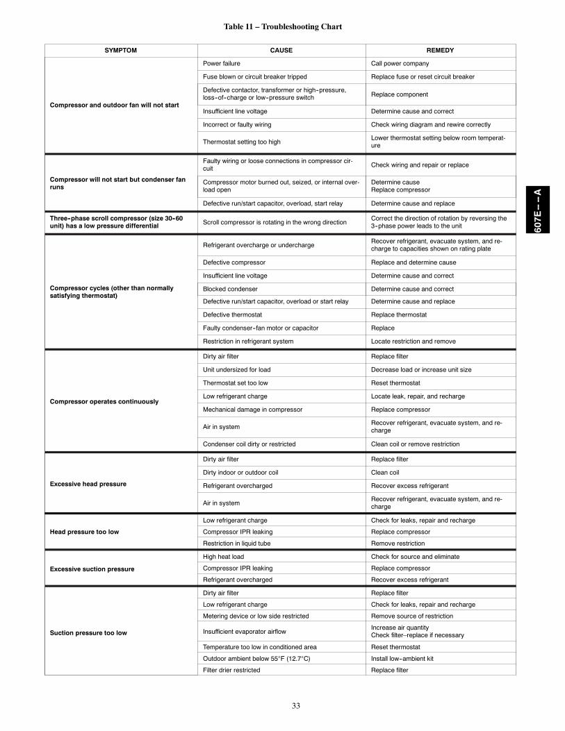
33
Table 11 – Troubleshooting Chart
SYMPTOM CAUSE REMEDY
Compressor and outdoor fan will not start
Power failure Call power company
Fuse blown or circuit breaker tripped Replace fuse or reset circuit breaker
Defective contactor, transformer or high--pressure,loss--of--charge or low--pressure switch Replace component
Insufficient line voltage Determine cause and correct
Incorrect or faulty wiring Check wiring diagram and rewire correctly
Thermostat setting too highLower thermostat setting below room temperat-ure
Compressor will not start but condenser fanruns
Faulty wiring or loose connections in compressor cir-cuit Check wiring and repair or replace
Compressor motor burned out, seized, or internal over-load open
Determine causeReplace compressor
Defective run/start capacitor, overload, start relay Determine cause and replace
Three--phase scroll compressor (size 30--60unit) has a low pressure differential Scroll compressor is rotating in the wrong direction
Correct the direction of rotation by reversing the3--phase power leads to the unit
Compressor cycles (other than normallysatisfying thermostat)
Refrigerant overcharge or underchargeRecover refrigerant, evacuate system, and re-charge to capacities shown on rating plate
Defective compressor Replace and determine cause
Insufficient line voltage Determine cause and correct
Blocked condenser Determine cause and correct
Defective run/start capacitor, overload or start relay Determine cause and replace
Defective thermostat Replace thermostat
Faulty condenser--fan motor or capacitor Replace
Restriction in refrigerant system Locate restriction and remove
Compressor operates continuously
Dirty air filter Replace filter
Unit undersized for load Decrease load or increase unit size
Thermostat set too low Reset thermostat
Low refrigerant charge Locate leak, repair, and recharge
Mechanical damage in compressor Replace compressor
Air in systemRecover refrigerant, evacuate system, and re-charge
Condenser coil dirty or restricted Clean coil or remove restriction
Excessive head pressure
Dirty air filter Replace filter
Dirty indoor or outdoor coil Clean coil
Refrigerant overcharged Recover excess refrigerant
Air in systemRecover refrigerant, evacuate system, and re-charge
Head pressure too low
Low refrigerant charge Check for leaks, repair and recharge
Compressor IPR leaking Replace compressor
Restriction in liquid tube Remove restriction
Excessive suction pressure
High heat load Check for source and eliminate
Compressor IPR leaking Replace compressor
Refrigerant overcharged Recover excess refrigerant
Suction pressure too low
Dirty air filter Replace filter
Low refrigerant charge Check for leaks, repair and recharge
Metering device or low side restricted Remove source of restriction
Insufficient evaporator airflowIncrease air quantityCheck filter–replace if necessary
Temperature too low in conditioned area Reset thermostat
Outdoor ambient below 55F (12.7C) Install low--ambient kit
Filter drier restricted Replace filter
607E----A

34
PURON (R--410A) QUICK REFERENCE GUIDE
Puron refrigerant operates at 50--70 percent higher pressures than R--22. Be sure that servicing equipment and replacement components aredesigned to operate with Puron. Puron refrigerant cylinders are rose colored.
S Puron refrigerant cylinders manufactured prior to March 1, 1999, have a dip tube that allows liquid to flow out of cylinder in upright
position.
Cylinders manufactured March 1, 1999 and later DO NOT have a dip tube and MUST be positioned upside down to allow liquid to flow.
S Recovery cylinder service pressure rating must be 400 psig. DOT 4BA400 or DOT BW400.
S Puron systems should be charged with liquid refrigerant. Use a commercial type metering device in the manifold hose.
S Manifold sets should be minimum 700 psig high--side and 180 psig low--side with 550 psig low--side retard.
S Use hoses with minimum 700 psig service pressure rating.
S Leak detectors should be designed to detect HFC refrigerant.
S Puron, as with other HFCs, is only compatible with POE oils.
S Vacuum pumps will not remove moisture from oil.
S Only use factory specified liquid--line filter driers with rated working pressures no less than 600 psig.
S Do not install a suction--line filter drier in liquid line.
S POE oils absorb moisture rapidly. Do not expose oil to atmosphere.
S POE oils may cause damage to certain plastics and roofing materials.
S Wrap all filter driers and service valves with wet cloth when brazing.
S A Puron liquid--line filter drier is required on every unit.
S Do not use an R--22 TXV.
S Never open system to atmosphere while it is under a vacuum.
S When system must be opened for service, break vacuum with dry nitrogen and replace filter driers.
S Always replace filter drier after opening system for service.
S Do not vent Puron into the atmosphere.
S Observe all warnings, cautions, and bold text.
S Do not leave Puron suction line driers in place for more than 72 hrs.
607E----A

35
START--UP CHECKLIST(Remove and Store in Job Files)
I. PRELIMINARY INFORMATIONMODEL NO.:
SERIAL NO.:
DATE:
TECHNICIAN:
II. PRESTART--UP (Insert check mark in box as each item is completed)( ) VERIFY THAT ALL PACKING MATERIALS HAVE BEEN REMOVED FROM UNIT
( ) REMOVE ALL SHIPPING HOLD DOWN BOLTS AND BRACKETS PER INSTALLATION INSTRUCTIONS
( ) CHECK ALL ELECTRICAL CONNECTIONS AND TERMINALS FOR TIGHTNESS
( ) CHECK THAT INDOOR (EVAPORATOR) AIR FILTER IS CLEAN AND IN PLACE
( ) VERIFY THAT UNIT INSTALLATION IS LEVEL
( ) CHECK FAN WHEEL, AND PROPELLER FOR LOCATION IN HOUSING/ORIFICE AND SETSCREW TIGHTNESS
III. START--UPELECTRICALSUPPLY VOLTAGE
COMPRESSOR AMPS
INDOOR (EVAPORATOR) FAN AMPS
TEMPERATURESOUTDOOR (CONDENSER) AIR TEMPERATURE DB
RETURN--AIR TEMPERATURE DB WB
COOLING SUPPLY AIR DB WB
HEAT PUMP SUPPLY AIR
ELECTRIC HEAT SUPPLY AIR
PRESSURESREFRIGERANT SUCTION PSIG, SUCTION LINE TEMP*
REFRIGERANT DISCHARGE PSIG, LIQUID TEMP{
( ) VERIFY REFRIGERANT CHARGE USING CHARGING CHARTS* Measured at suction inlet to compressor{ Measured at liquid line leaving condenser.
607E----A

36
Manufacturer reserves the right to discontinue, or change at any time, specifications or designs without notice and without incurring obligations.
E2013 Bryant Heating & Cooling Systems D 7310 W. Morris St. D Indianapolis, IN 46231 Edition Date: 05/13
Replaces: NEW
Catalog No. II607E---01
607E----A