Installation Instructions and Owner’s...
16
Sterling Water Treatment 12630 US Highway 33 N Churubusco, IN 46723 Phone (260) 693-1972 Fax (260) 693-0602 www.sterlingwatertreatment.com OXY3 Instruction Manual 112310.docx OXY3 Series Iron Reduction System Installation Instructions and Owner’s Manual
Transcript of Installation Instructions and Owner’s...

Sterling Water Treatment 12630 US Highway 33 N Churubusco, IN 46723
Phone (260) 693-1972 Fax (260) 693-0602 www.sterlingwatertreatment.com
OXY3 Instruction Manual 112310.docx
OXY3 Series
Iron Reduction System
Installation Instructions and Owner’s Manual

1
Description of the iron filtration system
The OXY3 iron filtration system includes an aeration tank, a filtration tank and a backwashing control valve. Incoming water flows into the control valve and is directed into the aeration tank. Exposure to the air in this tank will start oxidizing the iron. The water then flows through the back connector tube and into the filtration tank where the oxidized iron is trapped by the media. The iron-free water then returns to the control valve where it is directed into the service lines.
Periodically the control valve will go through a backwash cycle. This cycle will typically begin at 1:00 A.M. flushing the accumulated iron to the drain. Part of this backwashing process includes an air draw cycle which will replenish the pocket of air in the aeration tank and prepare the unit for the next period of service.
Water Quality
While the OXY3 filter will perform under a variety of water qualities there are a few things that need to
be considered to ensure satisfactory performance. The water should be tested to determine the concentration,
or levels of the items listed below.
pH - A measurement of the acidity of the water. pH is reported on a scale from 0 to 14. Neutral water
has a pH of 7.0, lower values indicate acidic water. The OXY3 iron filter performs best when the pH is 7.0, or
higher. pH values below 7.0 require a special media blend in the filter in order to elevate the pH for proper iron
oxidation.
Iron - A naturally occurring metallic element. Iron concentrations in excess of 0.3 milligrams/liter (mg/l)
combine with oxygen causing orange or red (rust) stains on plumbing fixtures. Iron naturally exists in some
water sources in either clear water (ferrous) state, red water (ferric) state or bacterial form. The OXY3 iron filter
can reduce any of these forms of iron.
Manganese - A naturally occurring metallic element. Manganese concentrations as low as 0.05
milligrams/liter (mg/l) can combine with oxygen to cause dark brown or black staining on fixtures. Additionally,
manganese can cause an odor in the water similar to a “rotten egg” smell. The OXY3 iron filter reduces
manganese as well as iron, however, manganese oxidation requires the pH of the water to be elevated to 8.2 or
higher. Special OXY3 media blends are available to elevate the pH of manganese bearing waters.
Tannin - A naturally occurring humic acid. Tannin is an acid caused by water passing through decaying
vegetation. Coffee and Tea are prime examples of tannin in water. As hot water passes over the coffee beans,
or tea leaves, the tannin is extracted causing color and flavor in the water. Tannin concentrations as low as 0.3
milligrams per liter can cause a yellow discoloration in the water and may interfere with the OXY3 iron filter’s
long-term ability to remove the iron as the media becomes coated with the tannic acid.
Hydrogen Sulfide - A naturally occurring gas. Hydrogen sulfide, more commonly referred to as sulfur
gas, causes a distinct odor similar to “rotten eggs.” Due to its gaseous nature, hydrogen sulfide must be tested
at the well site within 1 minute of drawing the sample. If a water sample has been sitting for a while the sulfur
gas will dissipate and cause the hydrogen sulfide test to be lower than the actual concentration. If sulfur is
present, the filter should be set to backwash more frequently to prevent the gas from building up. The OXY3
iron filter can typically treat up to 2 to 3 milligrams per liter of sulfur gas.
Preinstallation Instructions

2
Water Supply
Unlike other iron filters that do not use chemicals to oxidize the iron, the OXY3 iron filter does not require
additional plumbing such as solenoid valves, pressure switches or pressure tanks. This filter will function
properly when the water supply is furnished by a jet pump, submersible pump, variable speed (constant
pressure) pump or community water supply. As with all other filter systems, however, it is imperative that the
well pump provides enough flow rate for the filter to adequately backwash. In order to ensure sufficient
backwash flow rate the following pumping rate test should be performed prior to installing the iron filter.
1. Make certain no water is being drawn in the house.
2. Open spigot nearest pressure tank.
3. When well pump starts, close spigot and measure time (in seconds) to refill pressure tank (well pump turns back off). This is Cycle Time.
4. Using a container of known volume, draw water from pressure tank and measure how many gallons until the pump turns back on again. This is Draw Down.
5. Calculate pumping rate by dividing draw down by cycle time and multiplying by 60.
Draw Down (gallons)
X 60 = Pumping Rate (gallons per minute) Cycle Time (seconds)
Example: Draw down is 8 gallons
Cycle time is 65 seconds
Location Considerations
The proper location to install the OXY3 filter will ensure optimum filter performance and satisfactory
water quality. The following factors should be considered in selecting the location of the iron filter.
1. The filter should be installed after the pressure tank (private well system only).
2. The filter should be installed as close as possible (preferably within 15’) to an adequate floor or laundry drain capable of handling the backwash cycle volume and flow rate (refer to unit specifications).
3. All water conditioning equipment should be installed prior to the water heater. Water temperatures exceeding 100°F can damage the internal components of the control valve and filter tank.
4. The filter should not be subject to freezing temperatures.
5. The filter should be installed before a water softener (if required).
6. Never install a cartridge type filter prior to the OXY3 iron filter. Any cartridge or in-line filter (if desired) should be installed after the OXY3 filter. This will prevent restricting the water flow and pressure available for backwash.
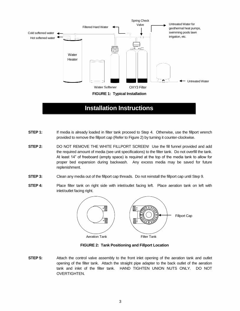
7. Appliances requiring extended periods of continuous or high flow water use (i.e. geothermal heat pumps, swimming pools, lawn irrigation, outside hose bibs, etc.) should bypass the filter and a spring check valve should be installed on the filter inlet to prevent backflow from the filter (see installation diagram Fig. 1).
8. An expansion tank may need to be installed in the line to the water heater in order to allow for thermal expansion and comply with local plumbing codes.
8 gallons X 60 = 7.4 gpm (gallons per minute)
65 seconds
3
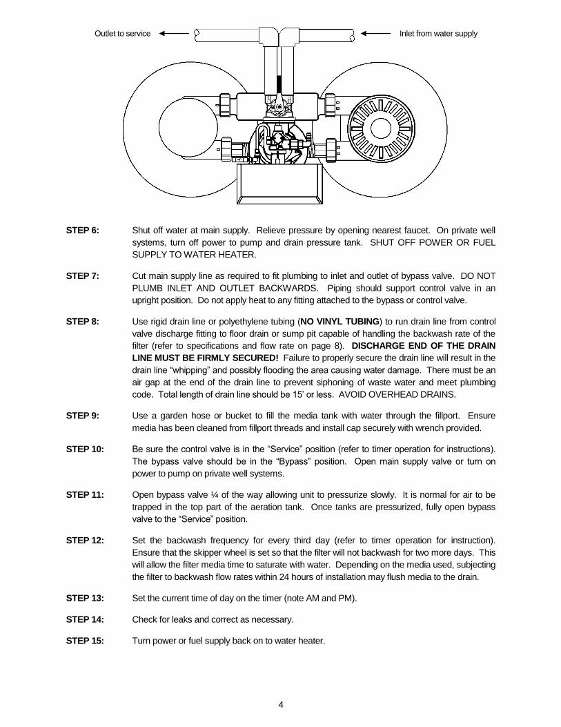
STEP 1: If media is already loaded in filter tank proceed to Step 4. Otherwise, use the fillport wrench
provided to remove the fillport cap (Refer to Figure 2) by turning it counter-clockwise.
STEP 2: DO NOT REMOVE THE WHITE FILLPORT SCREEN! Use the fill funnel provided and add
the required amount of media (see unit specifications) to the filter tank. Do not overfill the tank.
At least 14” of freeboard (empty space) is required at the top of the media tank to allow for
proper bed expansion during backwash. Any excess media may be saved for future
replenishment.
STEP 3: Clean any media out of the fillport cap threads. Do not reinstall the fillport cap until Step 9.
STEP 4: Place filter tank on right side with inlet/outlet facing left. Place aeration tank on left with
inlet/outlet facing right.
STEP 5: Attach the control valve assembly to the front inlet opening of the aeration tank and outlet
opening of the filter tank. Attach the straight pipe adapter to the back outlet of the aeration
tank and inlet of the filter tank. HAND TIGHTEN UNION NUTS ONLY. DO NOT
OVERTIGHTEN.
Water
Heater
Water Softener OXY3 Filter
Untreated Water
Untreated Water for
geothermal heat pumps,
swimming pools lawn
irrigation, etc. Cold softened water
Hot softened water
Filtered Hard Water
FIGURE 1: Typical Installation
Installation Instructions
Aeration Tank Filter Tank
Fillport Cap
FIGURE 2: Tank Positioning and Fillport Location
Spring Check
Valve
4
STEP 6: Shut off water at main supply. Relieve pressure by opening nearest faucet. On private well
systems, turn off power to pump and drain pressure tank. SHUT OFF POWER OR FUEL
SUPPLY TO WATER HEATER.
STEP 7: Cut main supply line as required to fit plumbing to inlet and outlet of bypass valve. DO NOT
PLUMB INLET AND OUTLET BACKWARDS. Piping should support control valve in an
upright position. Do not apply heat to any fitting attached to the bypass or control valve.
STEP 8: Use rigid drain line or polyethylene tubing (NO VINYL TUBING) to run drain line from control
valve discharge fitting to floor drain or sump pit capable of handling the backwash rate of the
filter (refer to specifications and flow rate on page 8). DISCHARGE END OF THE DRAIN
LINE MUST BE FIRMLY SECURED! Failure to properly secure the drain line will result in the
drain line “whipping” and possibly flooding the area causing water damage. There must be an
air gap at the end of the drain line to prevent siphoning of waste water and meet plumbing
code. Total length of drain line should be 15’ or less. AVOID OVERHEAD DRAINS.
STEP 9: Use a garden hose or bucket to fill the media tank with water through the fillport. Ensure
media has been cleaned from fillport threads and install cap securely with wrench provided.
STEP 10: Be sure the control valve is in the “Service” position (refer to timer operation for instructions).
The bypass valve should be in the “Bypass” position. Open main supply valve or turn on
power to pump on private well systems.
STEP 11: Open bypass valve ¼ of the way allowing unit to pressurize slowly. It is normal for air to be
trapped in the top part of the aeration tank. Once tanks are pressurized, fully open bypass
valve to the “Service” position.
STEP 12: Set the backwash frequency for every third day (refer to timer operation for instruction).
Ensure that the skipper wheel is set so that the filter will not backwash for two more days. This
will allow the filter media time to saturate with water. Depending on the media used, subjecting
the filter to backwash flow rates within 24 hours of installation may flush media to the drain.
STEP 13: Set the current time of day on the timer (note AM and PM).
STEP 14: Check for leaks and correct as necessary.
STEP 15: Turn power or fuel supply back on to water heater.
Inlet from water supply Outlet to service
5
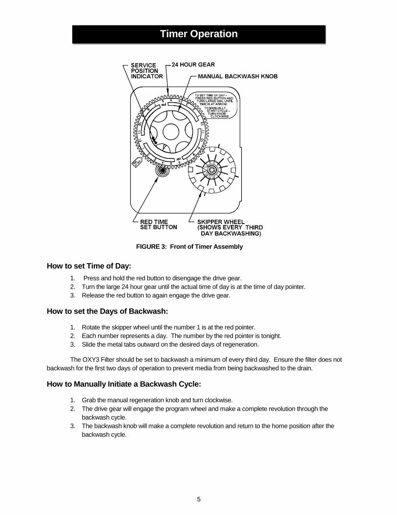
How to set Time of Day: 1. Press and hold the red button to disengage the drive gear.
2. Turn the large 24 hour gear until the actual time of day is at the time of day pointer.
3. Release the red button to again engage the drive gear.
How to set the Days of Backwash:
1. Rotate the skipper wheel until the number 1 is at the red pointer.
2. Each number represents a day. The number by the red pointer is tonight.
3. Slide the metal tabs outward on the desired days of regeneration.
The OXY3 Filter should be set to backwash a minimum of every third day. Ensure the filter does not
backwash for the first two days of operation to prevent media from being backwashed to the drain.
How to Manually Initiate a Backwash Cycle:
1. Grab the manual regeneration knob and turn clockwise.
2. The drive gear will engage the program wheel and make a complete revolution through the
backwash cycle.
3. The backwash knob will make a complete revolution and return to the home position after the
backwash cycle.
Timer Operation
FIGURE 3: Front of Timer Assembly

6
How to Change the Length of Backwash Cycles:
All cycles have been factory set and should not need adjustment. If local conditions require different
cycle lengths, however, the following procedures should be followed. The end of the program wheel has been
used for backwash cycles to minimize the amount of time that pressure will be applied to the air draw check
valve.
1. Grasp top left corner of timer assembly and pull to swing timer open and expose the program
wheel.
2. Remove program wheel from timer by squeezing retaining lugs in center of program wheel.
Maneuver program wheel away from micro switch arms and timer assembly.
3. BACKWASH cycle may be lengthened by adding pins to first set of pins on program wheel. Each
pin will equal 2 minutes of backwash time. Ensure that adding pins does not decrease air draw
time.
4. AIR DRAW cycle may be lengthened by increasing the number of holes between the two sets of
pins. Each hole represents 2 minutes of air draw time. The air draw time should only be increased
by moving the backwash pins to an earlier point on the program wheel. Ensure that lengthening
the air draw time does not decrease either the backwash or rapid rinse times.
5. RAPID RINSE cycle may be lengthened by increasing the number of pins at the end of the
program wheel. Each pin represents 2 minutes of rapid rinse time. The rapid rinse time can only
be increased by shifting both the backwash pins and air draw holes an equal number of positions
earlier on the program wheel.
6. Reinstall the program wheel on the retaining lugs by maneuvering past the micro switch arms.
7. Close and latch the timer assembly. Ensure that the retainer snaps into the hole in the backplate
and all electrical wiring is ABOVE the timer post.
FIGURE 4: Back of Timer Assembly

7
Control Valve Wiring

8
GENERAL REQUIREMENTS:
Water Temperature
33°F - 100°F
Water Pressure
25 - 100 psi
Electrical Requirements 110v/60hz
UNIT MODEL NUMBER
OXY3-10 OXY3-15 OXY3-20 OXY3-30 OXY3-40
MEDIA VOLUME (ft3) 1.0 1.5 2.0 3.0 4.0
GRAVEL (lbs) 20 20 25 35 50
SERVICE FLOW RATES (gpm)
Continuous (6 gpm/ft2) 3 4 5 6 8
Peak (20 gpm/ft2) 10 12 12 15 18
PRESSURE LOSS (psi)1
@ Continuous Flow Rate 5 7 7 8 9
@ Peak Flow Rate 10 15 13 20 20
REGENERATION FLOW RATES (gpm)
Backwash 5.0 5.0 7.0 9.0 10.0
Air Draw and Slow Rinse 0.9 0.9 0.9 0.9 0.9
Rapid Rinse 5.0 5.0 7.0 9.0 10.0
FACTORY REGENERATION SETTINGS
Backwash (minutes) 8 8 8 8 8
Air Draw & Rinse (minutes) 14 14 14 14 14
Rapid Rinse (minutes) 8 8 8 8 8
Total Water Used (gallons) 93 93 125 157 173
DIMENSIONS (in.)
Mineral Tank (diameter x height) 10 x 54 10 x 54 12 x 48 14 x 65 16 x 65
Overall (length x width x height) 24x 12 x 68 24 x 12 x 68 26 x 12 x 62 35 x 16 x 79 37 x 18 x 79
1. Pressure loss information is approximate and may vary based on frequency and efficiency of backwash, water quality, and water use since last backwash cycle.
Specifications

9
Component Parts Breakdown
A B C D
2
8
9
1
3
4
5
6
9
7
5

10
* Refer to unit specifications for quantity of media required.
OXY10P media is recommeded when incoming water pH is 7.0 or greater and no manganese is
present.
IP10 media is recommended when incoming water pH is less than 7.0 and no manganese is present.
IP10M media is recommended when manganese is present in water supply.
Ref # Part Number Description A CV3105 O-Ring, -215
B CV3151 Nut, 1” Quick Connect
C OX-7 Back Tube Adaptor (OXY3-10, OXY3-15 & OXY3-20)
OX-15 Back Tube Adaptor (OXY3-30 & OXY3-40)
D CV3150 Split Ring Retainer
1
OXY3-10/15 Valve Assembly Complete Control Valve includes backtube assy (ref #9) and bypass valve (OXY3-10 and OXY3-15)
OXY3-20 Valve Assembly Complete Control Valve (includes backtube assy) for OXY3-20
OXY3-30/40 Valve Assembly Complete Control Valve (includes backtube assy) for OXY3-30 and OXY3-40
2 CD1400 Distributor Head
3 CD1220-01 Distributor Head w/Fillport
4
D100S-54 Distributor Tube, 1” x 54” (OXY3-10 & OXY3-15)
D100S-48 Distributor Tube, 1” x 48” (OXY3-20)
D100S-65 Distributor Tube, 1” x 65” (OXY3-30 & OXY3-40)
5
MTP1054N Mineral Tank, 10” x 54” (OXY3-10 & OXY3-15)
MTP1248N Mineral Tank, 12” x 48” (OXY3-20)
MTP1465N Mineral Tank, 14” x 65” (OXY3-30)
MTP1665N Mineral Tank, 16” x 65” (OXY3-40)
6*
OXY10P OXY Media Blend
IP10 Iron Pro Media Blend
IP10M Iron Pro Media “M” Blend
7
QC20 20 pounds ¼” x 1/8” gravel (OXY3-10 & OXY3-15)
QC25 25 pounds ¼” x 1/8” gravel ( OXY3-20)
QC35 35 pounds ¼” x 1/8” gravel ( OXY3-30)
QC50 50 pounds ¼” x 1/8” gravel ( OXY3-40)
8 JG-38CV 3/8” Check Valve
9
OX-7 Assembly Back Tube Assembly, includes 2 each o-rings (A), quick release nuts (B), and retainers (D) and 1 back tube (C) (OXY3-10, OXY3-15 and OXY3-20)
OX-15 Assembly Back Tube Assembly, includes 2 each o-rings (A), quick release nuts (B), and retainers (D) and 1 back tube (C) (OXY3-30 and OXY3-40)
Component Parts List

11
Control Valve Breakdown

12
REF # Part
Number Description
REF #
Part Number
Description
A 60041SS Stainless Steel Bypass, 1” FPT 11 14805 Injector Body Gasket
B 60900-41 Coupling Kit
12 10328 90 Degree Elbow (1/4 Pipe x 3/8 Tube)
C JG-38CV Check Valve, 3/8” Tube
13
12092 5.0 DLFC (OXY3-10 &OXY3-15)
D 60011-020 Brine Valve, 1650 Short Stem, 0.5 BLFC Less Tube
12408 7.0 DLFC (OXY3-20)
E
60705-50 5.0 gpm DLFC Housing (OXY3-10 & OXY3-15)
Not used on 3 ft
3 and larger units
60705-70 7.0 gpm DLFC Housing (OXY3-20)
14 12338 Drain Fitting, Hose Barb, 90 Degree Elbow, 1/2" x 1/2"
60705-00 Blank DLFC Housing (larger than 3 ft
3)
15 19936 Base Seal (2510)
F 60121 Seal and Spacer Kit 16 19322 2510 Adapter Base
G 60090 Piston Assembly 17 19197 Slip Ring
H FV2510-1PH Powerhead Assembly, 2510 TC 18 18303 Tank O-Ring, 2510 Valve
I 60050-21 Drive Motor Assembly 19 13304 Distributor O-Ring, -121
J 60160-10 Drive Cam Assembly, STF 20 13030 Distributor Retainer
K 60304-13 Timer Assembly, 3200, 12 Day, STF, 120/60
21 40027 J tube for 2510 valve
1 14105 Bypass Valve Seal, Single Lever 22 13911 Main Drive Gear
2 13305 Coupling O-Ring, -019
23 18743-1 Timer Motor, 120v/60Hz, 2510/5600 Valve
3 19228-01 Coupling, Adapter S/ASSY 24 15320 Micro Switch, Homing
4 10692 Injector cover screw 2510 valve 25 10896 Micro Switch, Step
5 11893 Injector Cover 26 10218 Micro Switch, Drive Motor
6 10229 Injector Cover Gasket 27 10909 Connecting Link Pin
7 10913-2 Injector Nozzle, #2, Blue 28 10338 Roll Pin
8 10914-2 Injector Throat, #2, Blue 29 12777 Brine Cam, STF
9 10227 Injector Screen 30 60232-110 Valve Cover Designer Black
10 17776 Injector Body Plastic
Control Valve Parts List

13

14

15
WARRANTY – First Sales, LLC. warrants this water conditioner against any defects that are due to faulty material or workmanship during the warranty period. This warranty does not include damage to the product resulting from accident, neglect, misuse, misapplication, alteration, installation or operation contrary to printed instructions, or damage caused by freezing, fire, flood, or Acts of God. From the original date of consumer purchase, we will repair or replace, at our discretion, any part found to be defective within the warranty period described below. Purchaser is responsible for any shipping cost to our facility and any local labor charges.
One year on the entire water conditioner
Five years on the control valve
Ten years on the mineral tank GENERAL CONDITIONS – Should a defect or malfunction occur, contact the dealer that you purchased the product from. If you are unable to contact the dealer, contact First Sales, LLC. @ (260)693-1972. We will require a full description of the problem, model number, date of purchase, and selling dealer’s business name and address. We assume no warranty liability in connection with this water conditioner other than specified herein. This warranty is in lieu of all other warranties, expressed or implied, including warranties of fitness for a particular purpose. We do not authorize any person or representative to assume for us any other obligations on the sale of this water conditioner.
FILL IN AND KEEP FOR YOUR RECORDS ______________________________________________________________________ Original Purchaser Date of Purchase Model #
Address of Original Installation City State
Dealer Purchased From Dealer Address City State
Sterling Water Treatment Systems First Sales, LLC.
12630 U.S. 33 North, Churubusco, IN 46723
TEN YEAR LIMITED WARRANTY