INSTALLATION INSTRUCTIONS AND OWNER’S...
64
INSTALLATION INSTRUCTIONS AND OWNER’S MANUAL DIRECT VENT ZERO CLEARANCE GAS FIREPLACE HEATER MODEL SERIES: MULTIFUNCTION REMOTE (MF) DVLL48BP92(N,P)-1 DVLL60BP90(N,P)-1 UL FILE NO. MH30033 This appliance may be installed in an aftermarket, permanently located, manufactured home (USA only) or mobile home, where not prohibited by local codes. This appliance is only for use with the type of gas indicated on the rating plate. This appliance is not convertible for use with other gases, unless a certified kit is used. WARNING If not installed, operated and maintained in accordance with the manufacturer’s instructions, this product could expose you to substances in fuel or from fuel combustion which can cause death or serious illness. WARNING FIRE OR EXPLOSION HAZARD Failure to follow safety warnings exactly could result in serious injury, death or property damage. — Do not store or use gasoline or other flammable vapors and liquids in the vicinity of this or any other appliance. — WHAT TO DO IF YOU SMELL GAS • Do not try to light any appliance. • Do not touch any electrical switch; do not use any phone in your building. • Leave the building immediately. • Immediately call your gas supplier from a neighbor’s phone. Follow the gas supplier’s instructions. • If you cannot reach your gas supplier, call the fire department. — Installation and service must be performed by a qualified installer, service agency or the gas supplier. HOT GLASS DO NOT TOUCH NEVER WILL CAUSE BURNS. GLASS UNTIL COOLED. ALLOW CHILDREN TO TOUCH GLASS. WARNING A barrier designed to reduce the risk of burns from the hot viewing glass is provided with this appliance and shall be installed for the protection of children and other at-risk individuals. NOTE: Barrier required, may be sold separately. INSTALLER: Leave this manual with the appliance. CONSUMER: Retain this manual for future reference. GAS-FIRED
Transcript of INSTALLATION INSTRUCTIONS AND OWNER’S...

INSTALLATION INSTRUCTIONSAND OWNER’S MANUAL
DIRECT VENT ZERO CLEARANCE GAS
FIREPLACE HEATERMODEL SERIES:
MULTIFUNCTION REMOTE (MF) DVLL48BP92(N,P)-1 DVLL60BP90(N,P)-1 UL FILE NO. MH30033
This appliance may be installed in an aftermarket, permanently located, manufactured home (USA only) or mobile home, where not prohibited by local codes.This appliance is only for use with the type of gas indicated on the rating plate. This appliance is not convertible for use with other gases, unless a certified kit is used.
WARNINGIf not installed, operated and maintained in accordance with the manufacturer’s instructions, this product could expose you to substances in fuel or from fuel combustion which can cause death or serious illness.
WARNINGFIRE OR EXPLOSION HAZARDFailure to follow safety warnings exactly could result in serious injury, death or property damage.
— Do not store or use gasoline or other flammable vapors and liquids in the vicinity of this or any other appliance.
— WHAT TO DO IF YOU SMELL GAS• Do not try to light any appliance.• Do not touch any electrical switch; do
not use any phone in your building.• Leave the building immediately.• Immediately call your gas supplier
from a neighbor’s phone. Follow the gas supplier’s instructions.
• If you cannot reach your gas supplier, call the fire department.
— Installation and service must be performed by a qualified installer, service agency or the gas supplier.
HOT GLASS
DO NOT TOUCH
NEVER
WILLCAUSE BURNS.
GLASSUNTIL COOLED.
ALLOW CHILDRENTO TOUCH GLASS.
WARNING
A barrier designed to reduce the risk of burns from thehot viewing glass is provided with this appliance and shallbe installed for the protection of children and other at-riskindividuals.
NOTE: Barrier required, may be sold separately.
INSTALLER: Leave this manual with the appliance.
CONSUMER: Retain this manual for future reference.
GAS-FIRED

36459-9-0917Page 2
BEFORE YOU STARTSAMPLE WARNINGS AND DEFINITIONS:
DANGERIndicates a hazardous situation which, if not avoided, will result in death or serious injury.
WARNINGIndicates a hazardous situation which, if not avoided, could result in death or serious injury.
CAUTIONIndicates a hazardous situation which, if not avoided, could result in minor or moderate injury.
NOTICE: Addresses practices not related to personal injury.
1. Read the safety information on pages 57 - 58.2. If located in the Commonwealth of Massachusetts, please
note the special requirements on page 59.3. Areyougoingtoinstallablowerintothefireplace?See
pages 8 - 10.4. Whereareyougoingtoinstallthefireplace?Seepage13.5. Frametheopening.Seepage20.6. Installthegaslines.Seepages16-17.7. Installthewiring.Seepages18-19.8. Installtheventing.Seepages24-33.9. Installthefireplace.Seepages20-23.10. Installtheremotesystem.Seepages38-45.11. Linerrequirements.Seepage36.12. Installtheglassmedia.Seepage37.13. Lightthefireplaceandtroubleshoot.Seepages46-48.14. Showthehomeownerhowtooperatethefireplace.15. Showthehomeownerhowtodothebasicmaintenance.
UNPACKING THE FIREPLACE1. Cut binding straps and shrink wrap.2. Remove top board and corner posts.3. Liftfireplaceoffofthepallet.4. Remove non-combustible boards from pallet and set aside.5. Verifythatthefireplaceandcomponentshavenotbeen
damaged during shipping.6. Setfireplaceinalocationneartoitsfinalinstallationlocation.
INSTALLATION CONSIDERATIONS - FIREPLACE INSTALLATION GUIDELINESWhenplanningafireplaceinstallation,it’snecessarytodetermine:• Gassupplypiping(rightsideentrance).• Electricalsupplyrequirements
(120V,60Hz,1Amp)(rightsideentrance)• DVLL60BPmodelsincludethefactoryinstalledAccentLight
assembly.TheDVLL48BPmodelsdonotincludetheAccentLightassembly.However,theLK20AccentLightKitmaybepurchasedandinstalledduringorafterfireplaceinstallation.Instructions are supplied with the Accent Light kit.
• Properopeningsizeofframingrequiredforinstallationofthefireplace.Theframingofthefireplacewilldeterminehowthefireplacefinishingmaterialswillbeapplied.Refertotheinstallation information pages 20 to 23.
• Theblowerkitiseasiertoinstallatthetimeoffireplaceinstallations.Seeblowerinstallationsectiononpages8to10.
Inplanningtheinstallationforthefireplace,determinewherethefireplaceistobeinstalledandwhetheroptionalaccessoriesaredesired.Gassupplypipingshouldalsobeplannedatthistime.Thefireplacecanbemountedonanyofthesesurfaces:1. Aflathardcombustibleornon-combustiblesurface.2. A raised platform of combustible or non-combustible
material.
Ifthefireplaceisinstalleddirectlyoncarpeting,tileorothercombustiblematerialotherthanwoodflooring,itshouldbeinstalled on a metal or wood panel extending the full width and depthofthefireplace.Thefireplaceisdesignedtobeinstalledinazero-clearanceenclosure. This means that combustible materials must be locatedatclearancesspecifiedorprovidedbystandoffsorspacersattachedtothefireplace.Combustible materials can come in contact with the nailing flangesprovided.
HOMEOWNER REFERENCE INFORMATIONRecordthefollowinginformationaboutyourfireplace.
Model: ____________________________________ Datepurchased/installed: _________________
SerialNumber: _____________________________ Locationonfireplace: ____________________
Dealership: ________________________________ DealerPhone: _________________________
Notes: ______________________________________________________________________________
____________________________________________________________________________________

36459-9-0917 Page 3
CARTON CONTENTS & HARDWARE PACK
1
2
3
6
5
7
4
8
10
9
11
12
Items not shown to scale.
INDEX NUMBER DESCRIPTION QUANTITY
SUPPLIED
1 DoorRemovalTool(attachedtofireplace) 1
2 Product Registration Card 13 AA Battery 44 AAA Battery 3
5 WallThimbleSpacer(attachedtofireplace) 1
6 Cover Plate, Battery Box 17 Remote 18 Junction Box Cover 19 DuplexReceptacle 1
10 Flue Restrictor Assembly 111 Battery Box 112 Grommet,5/8DIA 113 Wire Assembly, Module to Interface 2A #10x1/2Screw 22B #8x1Self-DrillingScrew* 15C NailingFlange 4
*Foruseinmountingnon-combustibleboardtostandoffs.SeePartsListsonpages50fororderingreplacementparts.Donot order batteries, bolts, screws, washers or nuts. They are standard hardware items and can be purchased at any local hardware store.
13
1” PHILLIPS SELF DRILLING SCREW
#10 X ½” HEX HEAD SCREW
NAILING FLANGES
A
B
C

36459-9-0917Page 4
TABLE OF CONTENTS
INTRODUCTION ...........................................................................................................................5SPECIFICATIONS .........................................................................................................................6ACCESSORIES .............................................................................................................................7FBB20BLOWERINSTALLATION ......................................................................................... 8 - 10FIREPLACEDIMENSIONS .........................................................................................................11CLEARANCES ............................................................................................................................12LOCATINGFIREPLACE ..............................................................................................................13VENTTERMINATIONCLEARANCES ................................................................................ 14 - 15GASSUPPLY ...................................................................................................................... 16 - 17ELECTRICALCONNECTIONS ........................................................................................... 18 - 19INSTALLATION .................................................................................................................... 20 - 23VENTSYSTEMIDENTIFICATION ..............................................................................................24VENTSYSTEMS .........................................................................................................................24VENTINGFIREPLACE-TOP ............................................................................................. 25 - 27TOPVENT-HORIZONTALTERMINATION ...............................................................................28TOPVENT-VERTICALTERMINATION .....................................................................................29VERTICALTERMINATION .................................................................................................. 30 - 31DVVK-5FFLEXVENTINSTRUCTIONS ............................................................................. 32 - 33FRAMINGANDFINISHING ................................................................................................. 34 - 35LINERINSTALLATION ................................................................................................................36GLASSPLACEMENT ..................................................................................................................37MULTIFUNCTIONREMOTEOPERATINGINSTRUCTIONS ............................................. 38 - 45CONTROLSYSTEMTROUBLESHOOTING ...................................................................... 46 - 47LIGHTINGINSTRUCTIONS ........................................................................................................48PARTSVIEW ...............................................................................................................................50PARTSLIST.................................................................................................................................51COMPONENTWIRINGDIAGRAM .............................................................................................52MAINTENANCEANDSERVICE ......................................................................................... 53 - 56IMPORTANTSAFETYINFORMATION ............................................................................... 57 - 58SAFETYINFORMATIONFORUSERSOFLPGAS ...................................................................59REQUIREMENTSFORMASSACHUSETTS ..............................................................................60FIREPLACESERVICEHISTORY ...............................................................................................61MASTERPARTSDISTRIBUTORLIST .......................................................................................62HOWTOORDERREPAIRPARTS .............................................................................................62WARRANTY ................................................................................................................................63
SECTION PAGE

36459-9-0917 Page 5
Instructions to Installer1. Leave instruction manual with owner.2. HaveownerfilloutandmailProductRegistrationCard
suppliedwiththefireplace.3. Showownerhowtostartandoperatethefireplace.Thisdirect-ventgasfireplaceheaterisdesignedtooperatewithall combustion air being siphoned from the outside of the building and all exhaust gases expelled to the outside of the building. The information contained in this manual pertains to all models and gas control systems unless otherwise noted.
Appliance Certification
WARNINGThis fireplace is not for use with solid fuels. Solid fuels could cause personal injury or property damage.
ThisfireplaceisdesigncertifiedinaccordancewithAmericanNationalStandard/CSAStandardANSIZ21.88/CSA2.33andbyUnderwritersLaboratoriesasaDirectVentGasFireplaceHeaterand shall be installed according to these instructions.Consult your local building code agency, prior to installation, to ensure compliance with local codes-including permits and inspections.Thefireplace,wheninstalled,mustbeelectricallygroundedinaccordance with local codes or, in absence of local codes, with the National Electric Code ANSI/NFPA 70orCanadianElectriccode,CSAC22.1,ifanexternalelectricalsourceisutilized.These models may be installed in a bedroom or bed-sitting room intheU.S.A.andCanada.
Qualified Installing AgencyInstallationandreplacementofgaspiping,gasutilizationequipment or accessories and repair and servicing of equipment shallbeperformedonlybyaqualifiedagency.Theterm“qualifiedagency”meansanyindividual,firm,corporationorcompanywhich either in person or through a representative is engaged inandisresponsiblefor(a)theinstallationorreplacementofgaspipingor(b)theconnection,installation,repairorservicingof equipment, who is experienced in such work, familiar with all precautions required and has complied with all the requirements of the authority having jurisdiction.
Commonwealth of Massachusetts: The installation must be madebyalicensedplumberorgasfitterintheCommonwealthof Massachusetts.
WARNINGANY CHANGE TO THIS FIREPLACE OR ITS CONTROLS CAN BE DANGEROUS.Improper installation or use of the fireplace can cause serious injury or death from fire, burns, explosions, or carbon monoxide poisoning.
The installation must conform with local codes or, in the absence of local codes, with the National Fuel Gas Code ANSI Z223.1/NFPA 54* Natural Gas and Propane Installation Code, or CSA B149.1 in Canada. *Available from the American National Standards Institute, Inc. 11 West 42nd St., New York, N.Y. 10036.Any alteration of the original design, installed other than as shown in these instructions or use with a type of gas not shown on the rating plate is the responsibility of the person and company making the change.ImportantAllcorrespondenceshouldrefertocompleteModelNumber,SerialNumberandtypeofgas.
High Altitude Wheninstallingthisfireplaceatanelevationabove2000feet(intheUnitedStates)itmaybenecessarytodecreasetheinputratingbychangingtheexistingburnerorificetoasmallersize.Generally,inputshouldbereduced4percentforeach1000feetabovesealevel.However,iftheheatingvalueofthegashas been reduced, this general rule may not apply. Check with EmpireComfortSystemsforproperorificesizeidentification.
Canadian High Altitude Altitude:0-4500feet(0-1370m)Wheninstallingthisfireplaceatanelevationabove4500feet(inCanada),checkwithEmpireComfortSystemsforassistanceindeterminingtheproperorificeforlocation.
PreparationThisdirectventgasfireplaceanditscomponentsaretestedandsafe when installed in accordance with this installation manual. Reporttoyourdealeranypartsdamagedinshipment,specificallycheckglasscondition.Donotinstallfireplacewithdamaged,incomplete, or substitute parts. Read all instructions before starting installation and follow these instructions carefully during installationtoinsuremaximumbenefitandsafety.Failuretofollowthemwillvoidyourwarrantyandmaypresentafirehazard.The warranty will be voided by, and the warranter disclaims any responsibility for the following actions:• Installationofanydamagedfireplaceorventsystem
component.• Modificationofthefireplaceordirectventsystem.• InstallationotherthanasinstructedbyEmpireComfort
SystemsInc.• Improperpositioningoftheglassdoor,ordecorative
accessories including logs, rocks, crushed glass or other approved media.
• Installationand/oruseofanycomponentpartnotmanufactured or approved by manufacturer.
INTRODUCTION
36459-9-0917Page 6
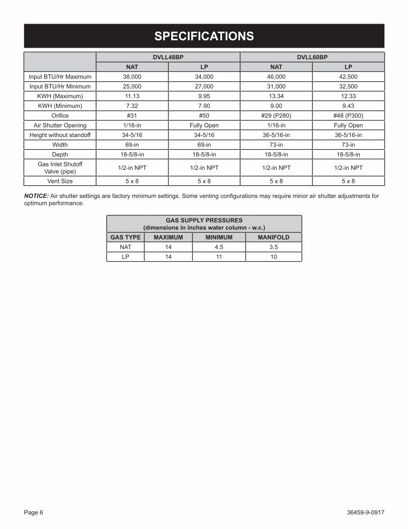
SPECIFICATIONSDVLL48BP DVLL60BP
NAT LP NAT LPInputBTU/HrMaximum 38,000 34,000 46,000 42,500InputBTU/HrMinimum 25,000 27,000 31,000 32,500
KWH(Maximum) 11.13 9.95 13.34 12.33KWH(Minimum) 7.32 7.90 9.00 9.43
Orifice #31 #50 #29(P280) #48(P300)AirShutterOpening 1/16-in FullyOpen 1/16-in FullyOpen
Heightwithoutstandoff 34-5/16 34-5/16 36-5/16-in 36-5/16-inWidth 69-in 69-in 73-in 73-inDepth 18-5/8-in 18-5/8-in 18-5/8-in 18-5/8-in
GasInletShutoffValve(pipe) 1/2-inNPT 1/2-inNPT 1/2-inNPT 1/2-inNPT
VentSize 5 x 8 5 x 8 5 x 8 5 x 8
NOTICE: Airshuttersettingsarefactoryminimumsettings.Someventingconfigurationsmayrequireminorairshutteradjustmentsforoptimum performance.
GAS SUPPLY PRESSURES(dimensions in inches water column - w.c.)
GAS TYPE MAXIMUM MINIMUM MANIFOLDNAT 14 4.5 3.5LP 14 11 10

36459-9-0917 Page 7
ACCESSORIESDescription Accessory Model #
ColorFireplace Models DVLL48BP DVLL60BPRidgebackLiner* DVP48LPZ DVP60LPZ BronzePorcelainLiner* DVP48LKR DVP60LKR GlossBlackTrimKit-Beveled DF48BL DF60BL BlackTrimKit-Beveled DF48HP DF60HP HammeredPewter
Beveled Window Frame - 2 inches DF482NB DF602NB NickelBrushedDecorativeFront,ForgedIron DFF48FPD DFF60FPD DistressedPewter
RusticContemporaryLogs&Stones LS48THF LS60THF N/AAccentLightKit LK8 N/A N/A
ConversionKit-LPtoNAT 36435 35470 N/AConversionKit-NATtoLP 36434 35469 N/A
*DVLL60BPmodelsrequireeitheraRidgebackLineroraPorcelainLiner.TheDVLL48BPfireplaceisshippedwithafactoryinstalledmetalliner.Ifdesired,itcanbereplacedwithoneoftheotherlineroptions.Thefireplacemusthavealinerinstalledpriortooperation.
**NOTICE:Iftheoptionalblowerkitisdesired,installationintothefireplacethroughtherearaccesspaneliseasier,priortoplacingthefireplaceintotheframedoutlocation.
Forapplicationandtheamountofcrushedglasstouse,refertothe“GlassPlacement”sectiononpage37.
ThefollowingaccessorypartscanbeobtainedfromyourEmpireComfortSystemsdealer.ContactyourEmpireDealerformoreaccessoryoptions.Ifyouneedadditionalinformationbeyondwhatyourdealercanfurnish,contactEmpireComfortSystemsInc.,918Freeburg Ave., Belleville, Illinois 62220-2623.
ACCESSORIES

36459-9-0917Page 8
FBB20 BLOWER INSTALLATION
1
1
2
BLOWER ASSEMBLY PARTS LIST
INDEX NO.
PART NO. DESCRIPTION QTY.
1 35727 BlowerAssembly-Single 2
2 R11788 WireHarness 1
TOOLS NEEDED:5/16inNutdriverorscrewgun
CAUTIONSharp edges. Use gloves when installing these blowers.
Installation - Prior to Setting Fireplace Into Final Position1. UnpacktheFBB20Blowerassembly.
2. Usinga5/16inhexdrive,removethe11screwsholdingrearblower access cover plate, then lay the access plate on the floor.See Figure 1.
Figure 1
3. Usearagtowipetheinsidebottomofthefireplace(wheretheblowerswillbeplaced)toremovedirtorconstructiondust.
4. Placeblowersonthefloorbehindthefireplace.Positionthe blowers with the two black connecting wires and green ground wire towards the left hand side when facing the back ofthefireplace.See Figure 2.
Figure 2
5. Locate the blower wire terminals inside the bottom of the fireplaceandmakethethreeconnectionsasshowninFigure 3.
Figure 3

36459-9-0917 Page 9
FBB20 BLOWER INSTALLATION (CONT’D)6. Begin installing the left blower assembly into the bottom of
thefireplace.Oncetheblowerisabouthalfwayin,securewiring within the white plastic wire retention clips provided in thefireplace.See Figure 4.
Figure 4
7. Finish installing the left blower so that the left edge of the blower base bracket is about even with the left edge of the access opening. Route the wiring away from the blower wheel. See Figure 5.
Figure 5
8. Next,installtherighthandblowerassemblytowardstheright side of the access opening. The right hand edge of the blower base bracket should be about even with the right edge of the access opening. Route wiring away from the blower wheel. See Figure 6.
Figure 6
9. Snapthewireharnessintothewhiteplasticwireretentioncliplocatedatthecenterbottomofthefireplace.See Figure 7.
Figure 7

36459-9-0917Page 10
FBB20 BLOWER INSTALLATION (CONT’D)10. Make sure the blower base brackets are pulled rearward
againstthebottomflangeofthefireplace.Themagnetsonthe blower base bracket will keep the blowers in place. See Figure 8.
Figure 8
11. Re-attach the Blower Access Panel with the 11 screws removed in step 2. See Figure 1.
12. Blower installation is complete.

36459-9-0917 Page 11
FIREPLACE DIMENSIONS
INDEX LETTER DIMENSION DESCRIPTION
DVLL48BP90 DVLL60BP90Dimensions in Inches
A Themaximumheightoffireboxface(excludingstandoffs) 34-1/4 36-1/4B Themaximumwidthofthefireboxface(excludingnailingflanges) 61 73C Themaximumdepthofthefirebox 19-1/2 19-1/2D Theheightofthefireboxopening 18 20E Thewidthofthefireboxopening 52-1/4 64-1/4F Theinteriordepthofthefirebox(notshown) 13 13
G Therearexteriorwidthofthefirebox 61 73H Theheighttothefireboxstandoffs 47-1/4 49-1/4I Width from the left side of the box to the centerline of vent 30-9/16 36-9/16J Depthfrombackofboxtocenterlineoftopvent 7-1/8 7-1/8K Heightfromthebottomoftheboxtothegaslineopening 14-3/4 14-3/4L Depthfromthefrontoftheboxtogaslineopening 14-11/16 14-11/16M Depthfromrearofboxtogaslineopening 3-3/4 3-3/4N Glassheight 13 15O Glasswidth 48 60P Depthfromfrontofboxtocenterlineofvent 12-3/8 12-3/8Q Distancefromfloortofireplaceopening 7-3/8 7-3/8R Heightfromfloortoventcollar 35-15/16 37-15/16S Overallheighttoheader 47-3/8 49-3/8T Distancebetweenframingbracketends 69-1/16 81-1/16U Interiorrearwidthoffirebox(notshown) 45 57V Bottomoffireplacetoscreenopening 10-1/8 10-1/8
O
B
N
I
C
J
P
E
DR
L M
K
A
G
Q
T
HS
V

36459-9-0917Page 12
CLEARANCESCLEARANCE TO COMBUSTIBLESBack SeeFig.10Side 3-in Floor 0-in
TopStand-offBracket 0-in TopFramingEdge 13-in
SEE MANTEL CHART FORMAXIMUM MANTEL DEPTH
13” MIN.
2” X 4” HEADER
STAND-OFF13” (76mm) HEIGHTABOVE TOP OF FIREPLACE
FINISHED WALL(COMBUSTIBLE)
NON-COMBUSTIBLEBOARD
TOP FRAMING LEDGESEE MANTEL CHARTFOR MINIMUM HEIGHT
OF MANTEL ABOVEUNIT OPENING
BARRIERSCREEN/GLASSFRONT
Note A: See Figure 12 for maximum mantel depth and minimum heightabovefireplace.
Figure 9
8”
3”
3” 2”
NOTE: COMBUSTIBLE MATERIALS ALLOWED IN SHADED AREA
3”
Figure 10
Theminimumclearancefrombottomofthefireplacetoceilingis65-in.The minimum clearance from side of the fireplace opening toadjacent sidewall is 8-in.
8” MIN.
(20cm)
TO BOTTOM
OF CABINET
CEILING
TO BOTTOM OF
VENTED OPENING
57 5/8” MIN
(146cm)
65” MIN
(165cm)
Figure 11
Mantel Chart
TOP EDGE OFFIREPLACE OPENING
H
22”
34”
12”
A
3”MINIMUM
NO
N-C
OM
BU
ST
IBL
E M
AT
ER
IAL
ZO
NE
INDEX LETTER
DISTANCE FROM FIREPLACE OPENING
(in inches)
DISTANCE FROM FINISHED WALL
(in inches)A 34 12B 34 10C 32 8-3/8D 30 6-5/8E 28 5F 26 3-3/8G 24 1-3/4H 22 0
Figure 12
Television ConsiderationsInstallingatelevisionaboveafireplacehasbecomeincreasinglypopular;however,theareaaboveanyfireplacegetshotandmostTV manufacturers recommend against placing their products near a heat source.Ifyouinstallatelevisionabovethisfireplace,EmpireComfortSystemsacceptsnoresponsibilityfordamageorinjuries.Followthetelevisionmanufacturer’sinstallationinstructions,includingany recommendations regarding proximity to heat sources.IfyouhaveaTVaboveyourfireplace,turnoffthefireplaceandlet it cool completely before servicing or touching any buttons on the TV.

36459-9-0917 Page 13
Figure 13
Note:IslandandRoomDividerinstallationispossibleaslongasthehorizontalportionoftheventsystemdoesnotexceed20feetwithaminimumverticalrunof8feet.SeedetailsinVentingSection.Note:Wheninstallingthisfireplaceagainstanexteriorwall,insulatetoapplicableinsulationcodes.WhenyouinstallyourDirectVentFireplaceinRoomdividerorFlatonwallcornerpositions,aminimumof8inchesclearancemustbemaintainedfromtheperpendicularwallandthefrontopeningofthefireplace.
LOCATING FIREPLACE
ROOM DIVIDERINSTALLATION
FLUSH WALLINSTALLATION
ISLANDINSTALLATION
CABINETINSTALLATION
CORNERINSTALLATION
ANGLED CORNERINSTALLATION

36459-9-0917Page 14
Termination clearance for buildings with combustible and noncombustible exteriors.
Vertical Sidewall InstallationsImportant! Minimum clearance between vent pipes and combustible materials is 3 inch(76mm)ontop,and1 inch(25mm)onbottomandsides.Important! When vent termination exits through foundation less than20inch(508mm)belowsidingoutcrop,theventpipemustextendoutwardsothatthehorizontalventterminationislocatedflushto,orbeyondtheoutcropsiding.Information on Various Venting Routes and ComponentsImportant:Itisalwaysbesttolocatethefireplaceinsuchawaythatminimizesthenumberofoffsetsandhorizontalventlength.Sinceitisveryimportantthattheventingsystemmaintainitsbalancebetweenthecombustionairintakeandthefluegasexhaust,certainlimitationsastoventconfigurationsapplyandmust be strictly adhered to.
Figure 14
VENT TERMINATION CLEARANCES
The graph showing the relationship between vertical and horizontalsidewallventingwillhelptodeterminethevariousventlengths allowable.Thehorizontalventrunreferstothetotallengthofventpipefromthefluecollarofthefireplacetothefaceoftheouterwall.Venting termination shall not be recessed into wall or siding.
ATTENTION: Vinyl Soffit, Vinyl Ceiling, Vinyl Overhang DisclaimerClearancesaretoheatresistantmaterial(i.e.wood,metal).Thisdoesnotincludevinyl.EmpireComfortSystemsInc.will not be held responsible for heat damage caused from terminating under vinyl overhangs, vinyl ceilings or vinyl ventilated/unventilatedsoffits.
RECESSED LOCATIONOUTSIDE CORNERINSIDE CORNER
“A” = COMBUSTIBLE 9” (229mm)= NONCOMBUSTIBLE 2” (51mm)
“F” = COMBUSTIBLE 6” (152mm)= NONCOMBUSTIBLE 6” (152mm)
BALCONYWITH PERPENDICULAR SIDE WALL
BALCONYWITH NO SIDE WALL
“C” = CLEARANCE FROM CORNERIN RECESSED LOCATIONCOMBUSTIBLE 9” (229mm)NONCOMBUSTIBLE 2” (51mm)
“D” = MINIMUM WIDTH FOR BACK WALLOF A RECESSED LOCATIONCOMBUSTIBLE 38” (965mm)NONCOMBUSTIBLE 24” (610mm)
“E” = MAXIMUM DEPTH OF 48” (1219mm)FOR RECESSED LOCATION
“G” = COMBUSTIBLE 9” (229mm)= NONCOMBUSTIBLE 2” (51mm)
“H” = COMBUSTIBLE 18” (457mm)= NONCOMBUSTIBLE 12” (305mm)
“I” = COMBUSTIBLE 12” (457mm)= NONCOMBUSTIBLE 12” (305mm)

36459-9-0917 Page 15
VENT TERMINATION CLEARANCES (CONT’D)
Canadian Installations1 USInstallations2 Canadian Installations1 USInstallations2
A= Clearance above grade, veranda, porch, deck, or balcony
12in(30cm) 12in(30cm)I= Clearance to service
regulator vent outlet 3ft(91cm) 6 ft
B= Clearance to window or door that may be open
6in(15cm)forappli-ances≤10,000Btuh (3kW),12in(30cm)for appliances > 10,000 Btuh(3kW)and≤100,000Btuh(30kW),36in(91cm)forappli-ances > 100,000 Btuh (30kW)
6in(15cm)forappli-ances≤10,000Btuh(3kW),9in(23cm)forap-pliances > 10,000 Btuh (3kW)and≤50,000Btuh(15kW),12in (30cm)forappliances>50,000Btuh(15kW)
J= Clearance to nonme-chanical air supply inlet to building or the combustion air inlet to any other appliance
6in(15cm)forappli-ances≤10,000Btuh(3kW),12in(30cm)forappliances > 10,000 Btuh(3kW)and≤100,000Btuh(30kW),36in(91cm)forappli-ances > 100,000 Btuh (30kW)
6in(15cm)forappli-ances≤10,000Btuh(3kW),9in(23cm)forappliances > 10,000 Btuh (3kW)and≤50,000Btuh(15kW),12in(30cm)forappliances > 50,000 Btuh (15kW)
C= Clearance to permanently closed window
12in(30cm) 12in(30cm)K=Clearancetoamechani-
cal air supply inlet 6ft(1.83m)3ft(91cm)aboveifwithin10ft(3m)hori-zontally
D=Verticalclearanceventilatedsoffitlocatedabove the terminal within ahorizontaldistanceof2feet(61cm)fromthecenter line of the terminal
24in(61cm) 24in(61cm)
L= Clearance above paved sidewalk or paved drive-way located on public property 7ft(2.13m)† 7ft(2.13m)†
E=Clearancetounventilatedsoffit 12in(30cm) 12in(30cm)
M= Clearance under veranda, porch deck, or balcony
12in(30cm)‡ 12in(30cm)‡
F= Clearance to outside corner 6in(15cm) 6in(15cm) 1 InaccordancewiththecurrentCSAB149.1,NaturalGasandPropaneInstal-
lation Code
G=Clearanceinsidecorner 9in(23cm) 9in(23cm) 2 InAccordancewiththecurrentANSIZ223.1/NFPA54,NationalFuelGasCode
H=Clearancetoeachsideof center line extended abovemeter/regulatorassembly
3ft(91cm)withinaheight15ft(4.5m)abovethemeter/regula-tor assembly
3ft(91cm)
† A vent shall not terminate directly above a sidewalk or paved driveway that is located between two single family dwellings and serves both dwellings
ATTENTION: Vinyl Soffit, Vinyl Ceiling, Vinyl Overhang DisclaimerClearancesaretoheatresistantmaterial(i.e.wood,metal).Thisdoesnotincludevinyl.EmpireComfortSystemsInc.willnotbeheldresponsible for heat damage caused from terminating under vinyl overhangs,vinylceilingsorvinylventilated/unventilatedsoffits.
‡ Permitted only if veranda,, porch, deck, or balcony is fully open on a minimum oftwosidesbeneaththefloor.
* ForclearancesnotspecifiedinANSIZ223.1/NFPA54orCSAB149.1,oneofthe following shall be indicated:
Clearance in accordance with local installation codes and the requirements of the gas supplier.

36459-9-0917Page 16
GAS SUPPLYThe gas pipeline can be brought in through the right side of the fireplace.ConsultthecurrentNationalFuelGasCode,ANSIZ223.1CAN/CGA-B149(.1or.2)installationcode.
Recommended Gas Pipe Diameter
Pipe Length
Schedule 40 PipeInside Diameter
(in inches)
Tubing, Type L Outside Diameter
(in inches)Nat. L.P. Nat. L.P.
0-10 feet 1/2 3/8 1/2 3/810-40 feet 1/2 1/2 5/8 1/2
40-100 feet 1/2 1/2 3/4 1/2100-150 feet 3/4 1/2 7/8 3/4
NOTICE:Neveruseplasticpipe.Checktoconfirmwhetheryourlocalcodesallowcoppertubingorgalvanized.NOTICE: Sincesomemunicipalitieshaveadditionallocalcodes,itis always best to consult your local authority and installation code.The use of the following gas connectors is recommended:— ANSIZ21.24ApplianceConnectorsofCorrugatedMetal
Tubing and Fittings.— ANSIZ21.45AssembledFlexibleApplianceConnectorsof
OtherThanAll-MetalConstructionThe above connectors may be used if acceptable by the authority having jurisdiction. The state of Massachusetts requires that a flexibleapplianceconnectorcannotexceedthreefeetinlength.
Figure 15
Gas Supply Pressure (inches w.c.)
Minimum Normal Maximum
NaturalGas 4.5 7.0 14.0
LP(Propane) 10.8 11.0 14.0
Manifold Pressure (inches w.c.)
Normal (HI)
NaturalGas 3.5
LP(Propane) 10.0
A gas valve and ground joint union should be installed in the gas line upstream of the gas control to aid in servicing. It is required bytheNationalFuelGasCodethatadriplegbeinstallednearthe gas inlet. See Figure 16. This should consist of a vertical length of pipe tee connected into the gas line that is capped on the bottom in which condensation and foreign particles may collect.
Figure 16
Installing a New Main Gas Shut-Off Valve (Check Local Code)Eachfireplaceshouldhaveitsownmanualgasshut-offvalve.A manual main gas shut-off valve should be located in the vicinity ofthefireplace.Wherenoneexists,orwhereitssizeorlocationisnotadequate,contactyourlocalauthorizedinstallerforinstallation or relocation.Compounds used on threaded joints of gas piping shall be resistanttotheactionofliquefiedpetroleumgases.Thegaslines must be checked for leaks by the installer. This should be done with a soap solution watching for bubbles on all exposed connections, and if unexposed, a pressure test should be made.
Never use an exposed flame to check for leaks. Fireplace must be disconnected from piping at inlet of control valve and pipe capped or plugged for pressure test. Never pressure test with fireplace connected; control valve will sustain damage!NOTICE: The gas control is equipped with a captured screw type pressuretestpoint,thereforeitisnotnecessarytoprovidea1/8inch test point up stream of the control. See Figure 17.Whenusingcopperorflexconnectoruseonlyapprovedfittings. Thefireplaceandit’sindividualshutoffvalvemustbedisconnected from supply piping system during any pressure testingofthatsystemattestpressuresinexcessof1/2psig(3.5kPa).Thefireplacemustbeisolatedfromthegassupplypipingsystemby closing its individual manual shut off valve during any pressure testing of the gas supply piping system at test pressures equal to orlessthan1/2psig(3.5kPa).Attention! If one of the procedures results in pressures in excess of1/2psig(14inw.c.)(3.5kPa)onthefireplacegasvalve,itwillresultinahazardouscondition.

36459-9-0917 Page 17
GAS SUPPLY (CONT’D)Checking Manifold PressuresBothPropaneandNaturalgasvalveshaveabuilt-inpressureregulatorinthegasvalve.Naturalgasmodelswillhaveamanifoldpressureofapproximately3.5-inw.c.(.871kPa)atthevalve outlet with the inlet pressure to the valve from a minimum of4.5-inw.c.(1.120kPa)forthepurposeofinputadjustmenttoamaximumof14.0-inw.c.(3.484kPa).Propanegasmodelswillhaveamanifoldpressureapproximately10.0-inw.c.(2.49kPa)at the valve outlet with the inlet pressure to the valve from a minimumof10.8-inw.c.(2.68kPa)forthepurposeofinputadjustmenttoamaximumof14.0-inw.c.(3.484kPa).
CAUTIONIf one of the procedures results in pressures in excess of 1/2 psig (14-in w.c.) (3.5 kPa) on the fireplace gas valve, it will result in a hazardous condition.
GAS VALVE
OUTLETPRESSURETAP
INLETPRESSURETAP
Figure 17
Gas Line ConnectionRemovetheaccesspanelfromtherightsideofthefireplaceshown in Figure 18toaccessthegasvalve,gasflexline,junction box, and system wiring.Attachthegasflexlinetothepre-installedgasline.RefertotheGasSupplysectioninthismanualfordetailsontheinstallationrequirements for the gas supply line.
14”
14 5/8
ACCESS PANEL
NAILING FLANGE
JUNCTION BOX
REMOTE WALL BOXWIRING EXIT POINT
GAS LINEACCESS
Figure 18

36459-9-0917Page 18
ELECTRICAL CONNECTIONS
CAUTIONAll wiring should be done by a qualified electrician and shall be in compliance with all local, city and state building codes. Before making the electrical connection, make sure that the main power supply is disconnected. The fireplace, when installed, must be electrically grounded in accordance with local codes, or in the absence of local codes, with the National Electrical Code ANSI/NFPA 70 (Latest Edition).
A factory installed junction box is located on the lower right sideofthefireplace.Wiringmustbefedtothejunctionboxandattached to the receptacle that is provided. Leave approximately 6in of wire in the junction box for connection.Attach black wire to one side of the receptacle and white wire to opposite side of receptacle. The ground wire should be attached tothegreen(ground)screw.See Figure 19.
BLACK (HOT)
BRASS SCREWS
JUNCTION BOX
GROUND
SILVER SCREWS
GREEN SCREWWHITE
(NEUTRAL)
120 VOLT POWER SUPPLY
Figure 19
Install the receptacle into the junction box. Attach cover plate.After the wiring is completed to the junction box and receptacle, installthejunctionboxtothelowerrightsideofthefireplaceasshown in figure 20.Insertthetopflangeoftheretainerbracketintotheslotonthefireplace.Rotatethejunctionboxassemblydownward, and secure with a screw below the junction box. See Figure 20.
Control Module Access:To access the control module for servicing, remove the barrier screen and glass door assemblies. The control module is located inthebottomrightsideopening.Remove(1)#10x1/2hexhead.Screwsthatsecuresthecontrolcover,thenshiftthecoverto the left and upward to remove. The control module is located tothefireplacebottomwithVelcro®,adncanbelifteduptoaccess the module wiring connections.
Figure 20

36459-9-0917 Page 19
OncetheJunctionboxhasbeeninstalledwiththereceptacleoutletsfacinginwardtowardsthefireplace,locatethe3-prongpower cord from the control module and plug into the receptical.
ThefireplaceissuppliedwithaUserInterfacewallboxthatmustbeinstalledinastandardplasticoutletbox(notprovided).Alowvoltage orange or blue box is recommended. The user interface wall box must be placed in the wall within ten feet from the right sideofthefireplace.A10ft.batteryanduserinterfaceextensionwire harness is supplied.
The red and black battery extension harness is connected to the red and black mating connector pre-installed on the control module.Thematingconnectorcanbelocatedinsidethefireplacenear the gas valve. See Figure 22.
Locateandinstallthe5/8indiameterplasticsnap-ingrommetover the low-voltage battery and interface extension harnesses at therightsideofthefireplace.Snapthegrommetintotheholeinthesideofthefireplacejustundertheaccesspanelopening.See Figure 22.
Run the extension wiring to the user interface wall box and connect the white connector to the remote receiver battery box. Install the battery box into the wall outlet box, then install the white remote cover supplied with the provided screws.
Figure 21
HAND BENTFLANGE
WIREGROMMET
USER INTERFACE HARNESS& BATTERY EXTENSION
HARNESS
CONNECT TO THE USER INTERFACE/BATTERYHOLDER. MUST BE INSTALLED IN A WALLJUNCTION BOX (ORANGE LOW VOLTAGE ORBLUE BOX RECOMMENDED)
NOTE: OUTER ACCESS DOOR REMOVED. REPLACE AFTER ALLWIRE AND GAS CONNECTIONS HAVE BEEN MADE
Figure 22
ELECTRICAL CONNECTIONS (CONT’D)

36459-9-0917Page 20
INSTALLATIONFramingThis fireplace can be elevated off the floor provided that the fireplace is properly supported by framing materials and the ceiling clearances are maintained.Fireplaceframingcanbebuiltbeforeorafterthefireplaceissetin place. Framing should be positioned to accommodate wall coveringandfireplacefacingmaterial.Thefireplaceframingshould be constructed of 2 x 4 lumber. Refer to Figure 23 for minimum framing dimensions.
CAUTIONMeasure fireplace dimensions and verify framing methods, and wall covering details before framing construction begins.
Framing dimension A includes a 13-inch clearance for framing standoffs on fireplace. After installing fireplace into framing, the non-combustible board must cover the 13-inch opening above the fireplace.
NOTICE:Forfinishingtotopoffireplace,refertoFigures 28 and 30.
B
C
A
C
INDEX NUMBER DVLL48 DVLL60
A 47-3/8in 49-3/8inB 67-5/8in 79-5/8inC 21-1/2in 21-1/2in
Figure 23
Construction of a Fireplace ChaseA chase is a vertical box-like structure built to enclose the gas fireplaceand/oritsventsystem.Incoolerclimatestheventshould be enclosed inside the chase. NOTICE: Treatment of ceiling firestops and wall shield firestops and construction of the chase may vary with the type of building. These instructions are not substitutes for the requirements of local building codes. Therefore, you MUST check local building codes to determine the requirements to these steps.A chase should be constructed in the manner of all outside walls of the home to prevent cold air drafting problems. The chase should not break the outside building envelope in any manner. Walls,ceiling,baseplateandcantileverfloorofthechaseshouldbeinsulated.Vaporandairinfiltrationbarriersshouldbeinstalledin the chase as per regional codes for the rest of the home. Additionally,inregionswherecoldairinfiltrationmaybeanissue,theinsidesurfacesmaybesheetrockedandtaped(oranequivalentmethodmaybeused)toachievemaximumairtightness.
Tofurtherpreventdrafts,thewallshieldandceilingfirestopsshould be caulked with caulk rated for a minimum of 300°F continuousexposureratingtosealgaps.Gaslineholesandother openings should be caulked or stuffed with unfaced insulation.Ifthefireplaceisbeinginstalledonacementsurface,a layer of plywood may be placed underneath to prevent conducting cold up into the room.
Framing and Finishing 1. Choosefireplacelocation.Seepages14-15.2. Frameinfireplacewithaheaderacrossthetop.Itis
importanttoallowforfinishedfacewhensettingthedepthofthefireplace.
3. SecurethefourframingbracketsandhandbendthemintoaV shape as shown in Figure 24.Securewith#10x1/2-inchhex-head screws.
4. Locatethenailingflangesonthesidesofthefireplace(twoeachside).See Figure 24.
Figure 24

36459-9-0917 Page 21
INSTALLATION (CONT’D)5. Securefireplacetoframingwithnailingflanges.Presetdepth
tosuitfacingmaterial(flushor1/2insetbackdepths).See Figure 25.
NAILING FLANGESSECURED TO
FRAMING
Figure 25
6. Attach three middle mount framing brackets to the top front edgeofthefireplace.Thesebracketssupportthesuppliednon-combustibleboardabovethefireplace.Presetdepthtosuitfacingmaterial(flushor1/2insetbackdepths).
See Figure 26.
FLUSH
½” SET BACK
MIDDLE MOUNTBRACKETS (3)
TOP FRONT EDGEOF FIREPLACE
Figure 26
Vent Pipe ClearanceNOTICE: Maintain one inch of clearance around vertical vent pipe. See Figure 27.
Forhorizontalvent,maintainaminimum1inchclearanceto the bottom and sides of the vent, and 3 inch clearance to combustibles above the vent pipe. See Figure 28.
VENT PIPE
1” MINIMUM CLEARANCE AROUNDVERTICAL VENT PIPE
Figure 27
Figure 28
Flush Wall Installation
NON-COMBUSTIBLE MATERIAL
2 X 4HEADER
FINISHED WALL
JOINT BETWEEN FINISHEDWALL AND UNIT SEALED
WITH 300°F (149°C)SEALANTMATERIAL
Figure 29

36459-9-0917Page 22
INSTALLATION (CONT’D)Finishing Methods
2” X 4” HEADER
FINISHED WALL(COMBUSTIBLE)
NON-COMBUSTIBLEBOARD
TOP FRAMINGLEDGE
Figure 30
2” X 4” HEADER
FINISHED WALL(COMBUSTIBLE)
NON-COMBUSTIBLEBOARD
TOP FRAMINGLEDGE
Figure 31
NON - COMBUSTIBLEBOARD FLUSH TOFIREPLACE FACE (SUPPLIED)
NON - COMBUSTIBLEBOARD OVERFIREPLACE FACE(NOT SUPPLIED)
Figure 32
Attention: Cold climate installation recommendation: When installingthisfireplaceagainstanon-insulatedexteriorwall,itis recommended that the outer walls be insulated to conform to applicable insulation codes.
Vent RunsInplanningtheinstallationforthefireplace,itisnecessarytoinstallcertaincomponentsbeforethefireplaceiscompletelypositioned and installed. These include the direct vent system, gas piping and electrical wiring. Thefireplacecanbemountedonanyofthefollowingsurfaces:1. Aflat,hardcombustibleornon-combustiblesurface.2. A raised wooden platform.
VERTICAL, 90-DEGREE ELBOW WITH HORIZONTAL TERMINATION
2’(610mm)
12” MINIMUM(305mm)
VERTICAL VENTREQUIRED
MAXIMUM HORIZONTALRUN WITH MINIMUMVERTICAL RISE AND
90° ELBOW
Figure 33
Finishing Options• Non-Combustibleboardinstalledoverthefireplaceface
(framingbracketflush).See Figure 29.• Non-Combustibleboardinstalledflushtoface(framing
bracketsat1/2-inchsetback).See Figure 30.• Figure 31showsbothfinishingoptions.• UseNon-Combustiblematerialswhereindicatedforthe
fireplaceinstallation.Non-combustiblematerialsdonotigniteorburnasaresultofusingthefireplace.Theseinclude metal, brick, ceramic, concrete, slate, glass and plaster. Adhesives must be rated for high temperatures. Any mechanical fasteners used to install material must also be non-combustible, including wall anchors and tile spacers. MaterialsthatpasstheASTME136test(StandardTestMethod for Behavior of Materials in a Vertical Tube Furnace at750C)areconsiderednon-combustible.

36459-9-0917 Page 23
INSTALLATION (CONT’D)VERTICAL, 90 DEGREE ELBOW TO HORIZONTAL OUT THE
WALL (12-in minimum rise before elbow)
90° ELBOW “A” PIPELENGTH
FIRESTOP SPACER(INCLUDED)
VENT CAP
WALL FIRESTOP/THIMBLE
B
C
A B C6-in 14-in 7in Maximum9-in 15-1/2-in-18-in 8-1/2-in-11-in
12-in 18-in-20-1/2-in 11-in-13-1/2-in
Figure 34
CORNER INSTALLATION - VERTICAL, 90 DEGREE ELBOW TO HORIZONTAL OUT THE WALL (12-in minimum rise before elbow)
NOTE: DIMENSIONS SHOWN WITH FRAMINGSET ½” BEHIND THE FIREPLACE FACE
A
DBC
Model A B C DDVLL48BP 101-5/8-in 51 71-7/8-in 23DVLL60BP 113-5/8-in 57 80-1/2-in 31-5/8-in
Figure 35Note: Corner installation will require more vertical vent pipe than just the minimum required depending on wall thickness and horizontaldimension.Refer to Figure 44, page 27.

36459-9-0917Page 24
Begin the vent system installation by selecting the type of venting to be installed and the path it will take. Verify clearances are met throughout the path of the venting system. NOTICE:Somefireplacescannotbeventedouttherearofthefireplace.Determinehowtheventsystemwillbeterminatedouttheside of the house or through the roof. Verify clearances for the termination.Whenselectingaventsystemforusewiththefireplace,refertothe“SpecialVentSystems”sectioninthismanualtodetermine
what systems are acceptable. Check all clearances and venting components. Identify if any problems exist in the vent system. UseFigure 44 on page 27 for top venting to eliminate issues after installation. Check pipe diameter on vent system and fireplacetoverifythesizeisthesame.NOTICE: All outer connection joints must be sealed with aluminum tape, screws or silicone sealant rated above 300°F/149°C. The inner flue joints do not require any sealant.
VENT SYSTEM IDENTIFICATION
Special DV Vent KitsAvailable from Empire Comfort Systems, Inc. dealers.
DVVK-5RPDirect-VentFireplaceVentKitforRearVent,6 to 12 inch wall thickness, Includes 58DVA-06,58DVA-WT,and58DVAHC
DVVK-5TP
Direct-VentFireplaceVentKitforTopVent,Thru-the-wall, 4 to 6 inch wall thickness, Includes58DVA-E90,58DVA-HC,58DVA-06,and58DVA-WT
DVVK-5VPDirectVentFireplaceVentKit-Vertical,Includes58DVA-VCH,58DVA-SC,and58DVA-F6
DVVK-5TS TopVentKit(Horizontal)-4½into6inwallthickness(114.3mmto152mm)
DVVK-5F HorizontalFlexVentKit(4'Flex)(1.22m)
VENT SYSTEMSThe following vent systems are acceptable for use with the DVLL60BP90seriesfireplaces:SimpsonDuravent®GS5in-8inAmerican Metal Products 5in - 8inSelkirkDirect-Temp®5in-8inSecuritySecureVent®5in-8inExcelDVVenting5in-8in
EmpireFlexventKitDVVK-5FBDM-5in-8inMetal Fab 5in - 8in
Figure 36
FLASHING
STORMCOLLAR
VERTICALTERMINATION(THREE 90°ELBOWS MAX)
WALLTHIMBLE
HORIZONTALTERMINATION
(THREE 90°ELBOWS MAX)
90° ELBOWOR
45° ELBOW
90° ELBOW
CEILINGFIRE STOP
WALL STRAP
PIPE LENGTH
THIMBLESPACER

36459-9-0917 Page 25
VENTING FIREPLACE - TOP
WARNINGUse flue restrictor for vertically terminated fireplaces only. Do not use for horizontally terminated fireplaces.
Figures 37 to 40 show the location and recommended opening forthefluerestrictor.Installation of restrictor before venting is attached. See Figure 37.
Figure 37NOTICE: Wheninstallingfluerestrictor,installwithscrewpointingdownward.For installation of the restrictor after the venting is installed, remove(2)screwsfromeachendofthefluebaffleandsetaside.Inserttherestrictorupintothefluecollarandpositionitasshownin Figures 38 and 39.Then,re-installthefluebaffle.
REMOVE BAFFLETO INSTALLFLUE RESTRICTOR
FLUE RESTRICTOR
Figure 38
REMOVE BAFFLETO INSTALLFLUE RESTRICTOR
FLUE RESTRICTOR
Figure 39
Figure 40
A1
CENTER OF ELBOW
STRAIGHT OUT
(MINIMUM)
A2
CENTER OF ELBOW
STRAIGHT OUT
(MINIMUM)
FIREPLACESERIES
HARD ELBOW DIMENSIONSA1 B C D
DVLL48 52-3/4-in 5-3/8-in 7-5/8-in 10-5/8-inDVLL60 54-3/4-in 5-3/8-in 7-5/8-in 10-5/8-in
FIREPLACESERIES
FLEX PIPE 90 DEGREE BENDA2 B C D
DVLL48 52-3/4-in 5-3/8-in 7-5/8-in 10-5/8-inDVLL60 54-3/4-in 5-3/5-in 7-5/8-in 10-5/8-in
MINIMUM HOLE LOCATION DIMENSIONS FOR THROUGH-THE-WALL HORIZONTAL INSTALLATIONS WITH 90 DEGREE ELBOW AND 12-in RISE OFF TOP OF FIREPLACE
SEE FIGURE 44 ON PAGE 27 FOR PERMISSIBLE HORIZONTAL AND VERTICAL RUN DIMENSIONS.
Figure 41

36459-9-0917Page 26
VENTING FIREPLACE - TOP (CONT’D)Positioning the FireplaceDeterminetheexactpositionofthefireplacesothedirect-ventterminationwillbecentered(ifpossible)betweentwostuds.This will avoid any extra framing. All vent kit pipes should be assembledonthefireplaceafterthefireplaceismovedintothefinalposition.
Cutting the HoleAfterthefireplacehasbeenpositionedinitspermanentlocation,the hole through the exterior wall can be cut. This hole must be 13-in(330mm)highx10-5/8-in(270mm)widewithitscenterlinedeterminedbytheamountofverticalriseandhorizontalrunofthe termination. See Figures 42 and 43. When locating the hole it must be noted that the bottom of the cap must be minimum of 12-in(305mm)abovethegroundlevel,andtopofthecapmustbenolessthan18-in(457mm)belowacombustibleprojection,andnocloserthan9-in(229mm)toanywallrunningparalleltovent termination.
U:\INSTRUCTIONS\Instructions Original Graphics\DVLL60BP\DVLL Vent Cap Clearance - 061515
Figure 42
Below Grade InstallationWhen it is not possible to meet the required vent termination clearancesof12inch(305mm)abovegradelevel,asnorkelkit is recommended. It allows installation depth down to 7 inch (178mm)belowgradelevel.The7inch(178mm)ismeasuredfromthecenterofthehorizontalventpipeasitpenetratesthrough the wall.Ensure the sidewall venting clearances are observed. If venting system is installed below ground, we recommend a window well with adequate and proper drainage to be installed around the termination area.
TYPICAL BASEMENT INSTALLATION
12” (30.5cm) ABOVEGRADE OR AVERAGE
EXPECTED SNOW LEVEL
Figure 43
ATTENTION: Vinyl Soffit, Vinyl Ceiling, Vinyl Overhang DisclaimerClearancesaretoheatresistantmaterial(i.e.wood,metal).Thisdoesnotincludevinyl.EmpireComfortSystemsInc.will not be held responsible for heat damage caused from terminating under vinyl overhangs, vinyl ceilings or vinyl ventilated/unventilatedsoffits.

36459-9-0917 Page 27
To Use the Vent Graph1. Determinetheheightofthecenterofthehorizontalvent
pipe.UsingthisdimensionontheSidewallVentGraph,locate the point it intersects with the slanted graph line.
2. From the point of this intersection, draw a vertical line to the bottom of the graph.
3. Selecttheindicateddimension,andpositionthefireplaceinaccordance with same.
EXAMPLE A:Iftheverticaldimensionfromthefloorofthefireplaceis32feet,thehorizontalruntotheouterwallflangemustnotexceed5feet.EXAMPLE B:Iftheverticaldimensionfromthefloorofthefireplaceis24feet,thehorizontalruntotheouterwallflangemustnotexceed10feet.
VENTING FIREPLACE - TOP (CONT’D)EXAMPLE C:Ifthehorizontalruntotheouterwallflangeis17feet,theverticaldimensionfromthefloorofthefireplacetothecenterofthetermination must not be less than 7 feet 6 inches.SPECIAL NOTE: Foreach45°elbowinstalledinthehorizontalrun,thelengthofthehorizontalrunMUSTbereducedby18inches. Reduce by 3 feet for every 90° elbow. This does not apply if the 45° elbows are installed on the vertical part of the vent system. Example:Accordingtothechartthemaximumhorizontalvent length is 20 feet and if two 45° elbows are required in the horizontalventitmustbereducedto17feet.The maximum number of 45° elbows permitted per side wall installation is two. These elbows can be installed in either the verticalorhorizontalrun.The maximum number of 90° elbows in a vent run is three.
Acceptableverticalandhorizontalventrun. (40'maximumverticaland20'maximumhorizontal)
Unacceptableverticalandhorizontalventrun. SeetextaboveforExamplesA,BandC.
Figure 44
VENTING GRAPH (Dimensions in Feet)
A
C
B
HORIZONTAL RUN
VE
RT
ICA
LD
IME
NS
ION
FR
OM
TH
E B
OT
TO
M O
FT
HE
UN
ITT
OT
HE
CE
NT
ER
OF
TH
EF
LU
E O
UT
LE
TW
ITH
VE
RT
ICA
LO
R H
OR
IZO
NTA
LT
ER
MIN
AT
ION
S C
AP
S

36459-9-0917Page 28
TOP VENT - HORIZONTAL TERMINATIONOne 90° Elbow
ATO BOTTOM
OF UNIT
B
INSTALLEDVERTICALLY
1’MINIMUM
EXAMPLE VENT RUNSINITIAL PIPE
LENGTH A (Vertical) B (Horizontal)MAXIMUM
(Dimensions in inches)
12 55 NAT-24LP - 12
24 67 4236 79 108(9ft)48 91 168(14ft)
Figure 45Note: Pipe straps must be used every 2 feet to secure venting.
Two 45° ElbowsInstallation requirements to replace the first 90° elbowwith two45° elbows:
B
A
EXAMPLE VENT RUNSINITIAL PIPE
LENGTH A (Vertical) B (Horizontal)MAXIMUM
(Dimensions in inches)12 66 7224 80 132(11ft)36 91 204(17ft)48 103 240(20ft)
Figure 46
Two 90° ElbowsNote:Subtract3 feet from the totalhorizontalmeasurement foreach 90° elbow installed horizontally. Subtract 1-1/2 feet fromthe total horizontal measurement for each 45° elbow installedhorizontally.
EXAMPLE VENT RUNSINITIAL PIPE
LENGTH A (Vertical) B (Horizontal)MAXIMUM
(Dimensions in inches)12 55 0’24 67 636 79 72(6ft)48 91 132(11ft)
Figure 47Three 90° Elbows
1’MININUM
B
INSTALLEDVERTICALLY
INSTALLEDVERTICALLY
ATO BOTTOM
OF UNIT
EXAMPLE VENT RUNSINITIAL PIPE
LENGTH A (Vertical) B (Horizontal)MAXIMUM
(Dimensions in inches)12 55 1824 67 24(2ft)36 79 90(7ft,6in)48 91 114(9ft,6in)
Figure 48
36459-9-0917 Page 29
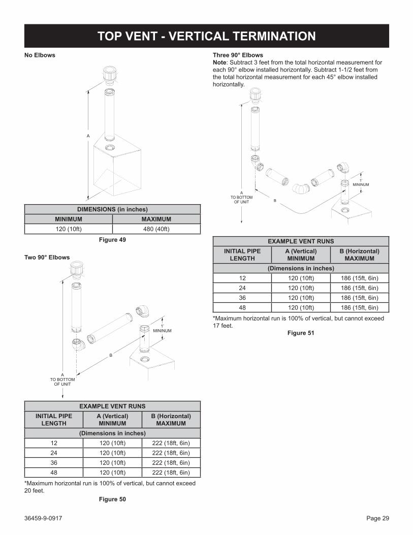
TOP VENT - VERTICAL TERMINATIONNo Elbows
DIMENSIONS (in inches)MINIMUM MAXIMUM120(10ft) 480(40ft)
Figure 49
Two 90° Elbows
EXAMPLE VENT RUNSINITIAL PIPE
LENGTHA (Vertical)MINIMUM
B (Horizontal)MAXIMUM
(Dimensions in inches)12 120(10ft) 222(18ft,6in)24 120(10ft) 222(18ft,6in)36 120(10ft) 222(18ft,6in)48 120(10ft) 222(18ft,6in)
*Maximumhorizontalrunis100%ofvertical,butcannotexceed20 feet.
Figure 50
Three 90° ElbowsNote:Subtract3feetfromthetotalhorizontalmeasurementforeach90°elbowinstalledhorizontally.Subtract1-1/2feetfromthetotalhorizontalmeasurementforeach45°elbowinstalledhorizontally.
EXAMPLE VENT RUNSINITIAL PIPE
LENGTHA (Vertical)MINIMUM
B (Horizontal)MAXIMUM
(Dimensions in inches)12 120(10ft) 186(15ft,6in)24 120(10ft) 186(15ft,6in)36 120(10ft) 186(15ft,6in)48 120(10ft) 186(15ft,6in)
*Maximumhorizontalrunis100%ofvertical,butcannotexceed17 feet.
Figure 51

36459-9-0917Page 30
VERTICAL TERMINATIONLocate and mark the center point of the vent pipe using a nail on theundersideoftheroof.Drivethenailthroughthecenterpoint.Mark the outline of the roof hole around this center point.NOTICE:Sizeoftheroofholedimensionsdependonthepitch
oftheroof.Theremustbea1inch(25mm)clearanceto the vertical pipe sections. This clearance is to all combustible material.
Cover the opening of the vent pipe and cut and frame the roof hole.Useframinglumberthesamesizeastheroofraftersandinstall the frame securely. Flashing anchored to frame must withstand high winds. The storm collar is placed over this joint to makeawater-tightseal.Non-hardeningsealantshouldbeusedtocompletelysealthisflashinginstallation.
Determining Minimum Vent Height Above the Roof.
WARNINGMajor U.S. building codes specify minimum chimney and/or vent height above the roof top. These minimum heights are necessary in the interest of safety. These specifications are summarized in Figure 55.
VENT CAP
GAS VENT
24”
24”
MORETHAN
10 FEET
Figure 52
Notethatforsteeproofpitches,theventheightmustbeincreased. In high wind conditions, nearby trees, adjoining roof lines, steep pitched roofs, and other similar factors can result in poor draft, or down-drafting. In these cases, increasing the vent height may solve this problem.
Installing the Vent System in a ChaseA chase is a vertical box-like structure built to enclose the gas fireplaceand/oritsventsystem.Verticalventrunsontheoutsideof a building may be, but are not required to be installed inside a chase.
CAUTIONTreatment of firestop spacers and construction of the chase may vary with the type of building. These instructions are not substitutes for the requirements of local building codes. Check local building codes to determine the requirements for these steps.
NOTICE: Build the chase large enough to maintain the minimum clearanceofcombustiblematerials(includinginsulation)tothevent system. When installing the vent system in a chase, insulate the chase as you would the outside walls of your home. This is especiallyimportantincoldclimates.Uponcompletionofchaseframing, install the vent system by following the instructions in this manual.Theverticalterminationcapforthisfireplacemustnotbeanycloser than 24-in. to combustible materials. See Figure 53.
40’(12.19M)
MAX
24” MINIMUMCLEARANCE TOCOMBUSTIBLES
NATURAL ORMAN MADE
8’ (2.44M)MAX
8’ (2.44M)MAX
45°
45°
Figure 53
If two vertical terminations are run near each other, they may be placed a minimum of 12 inches between them if they are at the same height. See Figure 54. If two vent terminations are not at the same height, they must be positioned at least 24 inches apart tominimizedraftissuesbetweenthem.
12”MINIMUM
Figure 54

36459-9-0917 Page 31
Vertical Through-the-Roof ApplicationsYourGasFireplacehasbeenapprovedfor:a) Verticalinstallationsupto40feetinheight.b) Twosetsof45degreeelbowoffsetswithinthesevertical
installations. From 0 to a maximum of 8 ft. a vent pipe can be used between elbows.
c) Wallstrapsmustbeusedtosupportoffsetpipeevery4’.Thisapplicationwillrequirethatyoufirstdeterminetheroofpitchand use the appropriate venting components.OFFSET CHART
RISE
OFFSET
SIZE 5-in X 8-in
ELBOWDEGREES
CHIMNEYSECTION
OFFSETINCHES
RISEINCHES
Dimensions in Inches45° 0 5-5/8 15-3/845° 6 8-7/8 18-3/845° 9 10-7/8 20-5/845° 12 13 22-5/845° 24 21-3/8 31-1/845° 36 29-7/8 39-3/845° 36 28-7/8 39-3/845° 48 38-1/4 47-7/8
Figure 55
General MaintenanceInspect venting system semi-annually as follows:1. Check for corrosion areas of the venting system exposed
to the elements. These will appear as rust spots or streaks and, in extreme cases, holes. Replace damaged components should immediately.
2. Removethecapandshineaflashlightdownthevent.Remove any bird nests or other foreign material.
3. Check for evidence of excessive condensate, such as water droplets forming in the inner liner and subsequently dripping out at joints. Condensate can cause corrosion of caps, pipe andfittings.Itmaybecausedbyhavingexcessivelateralruns, too many elbows and exterior portions of the system being exposed to cold weather.
4. Inspectjointstoverifythatnopipesectionsorfittingshavebeen disturbed and, consequently, loosened. Also, check mechanicalsupports,suchaswallstrapsorplumbers’tapefor rigidity.
Venting termination shall not be recessed into a wall or siding.A removable panel or other means must be provided in the enclosureforvisualinspectionoftheflueconnection.NOTICE: This also pertains to vertical vent systems installed on the outside of the building.Slidetheverticalventcapovertheendsoftheventpipeandsecure. See Figure 56.
Figure 56
VERTICAL TERMINATION (CONT’D)

36459-9-0917Page 32
DVVK-5F FLEX VENT INSTRUCTIONSThe DVVK-5F FLEX VENT KIT includes the following components:• (1)HorizontalTerminationCap• (1)4-footsectionofFlexventwithspacers(5-inchflue/
8-inchouterpipe)withflueadaptercollar• (1)WallFirestop/ThimbleAssembly• Hardwarepackthatincludesbandclampsandscrews
Maintain at least ½-inch rise for every 12 inches of vent run.
CAUTION• Because of sharp edges, always use gloves when
handling the flex vent components.• Always follow the general venting requirements for
vent terminal location, vent lengths, and clearance to combustible materials.
• Always stretch and secure venting with wire or metal strapping to ensure that the horizontal runs do not sag.
• Vent connections should overlap a minimum of 1 inch for proper sealing.
INSTALLATION1. Unpackventcomponentsandcheckthatallitemsare
included.2. Check to see that the vent spacer springs are located around
theflueventat8inchintervalsalongitslength.See Figures 57 & 58. If not, stretch the spacer springs to about 15 inches longandwrapthemaroundtheflue,theninterlocktheendsof each spring. Maintain equal distance between spring spacers.
Figure 57
5” FLEXVENT PIPE
SPACERSPRING
8” FLEXVENT PIPE
Figure 58
3. Attach a 6-inch piece of hard pipe to raise the connection pointabovethefireplace.
4. Useexisting8-inchdiameterinletcollartoattachouterventpipe.
5. InstalltheWallFirestop/Thimbleassemblyasrequiredthrough the wall. Refer to the venting charts in the fireplace manualtodeterminetheproperheightandsizeoftheventopening. The minimum opening should be 10-inches wide by 12-inches high. The minimum combustible clearance from thehorizontalventis1inchfromsidesandbottom,and3inches above the vent pipe.
6. In most cases, after determining the length of the vent that is needed, it may be easier to install the flue and outer vent pipes to the Termination Cap first, then from the outside, feed the venting through the wall to the fireplace.
7. If the venting is to long, trim off any excess vent before attaching the vent end connectors.
8. Attach the Termination Cap to the outside of the house.
CAUTIONDo not use force when installing the Horizontal Vent Termination into the flex venting. Always stretch venting out first, then cut off excess vent material prior to sliding the vent termination into the flue and inlet venting. Forcing the termination cap into the flex venting will deform the flue venting, which will restrict the exhaust gases, and cause improper operation of the fireplace.

36459-9-0917 Page 33
DVVK-5F FLEX VENT INSTRUCTIONS (CONT’D)9. Prior to making the vent connections, apply high temperature
sealant(1000°Fmin.)totheventconnectionsbeforesecuringwiththebandclampsprovided.Note:thefluepipeend without the adapter is to be installed to the Termination Cap.
10. Apply sealant to the outside of the flue pipe adapter and connect to the flex flue pipe. Then insert the adapter into the fireplaceflue.Secureflueadaptertothefireplacefluewithaminimum of two screws provided. See Figure 59.
11. AttachtheOuterVentpipetothe8-inchdiametercollaronthefireplacewithalargebandclampprovided.Sealantmayalso be used on the outer vent connections.
12. Check all vent connections for tightness. Make sure horizontalventinghastheproperriseandcombustibleclearances required. Refer to venting charts in fireplace instruction manual.8” DIAMETER FLEXVENT PIPE
5” DIAMETER FLEXFLUE PIPE
5” DIAMETERFLUE ADAPTORCOLLAR
8” DIAMETERFIREPLACEINLET COLLAR
Figure 59
Figure 60

36459-9-0917Page 34
FRAMING AND FINISHINGInstalling Support BracketsInstallahorizontalpipesupportusedforeach3feetofhorizontalrun to framing members. Allow 3 inch clearance to combustibles above 8-inch diameter pipe and elbows, and 1 inch clearance to both sides and bottom.Supportverticalrunsofthisventsystemsevery4feetusingwallbrackets attached to the vent pipe, then secured with nails or screws to structural framing.
Figure 61
Installing FirestopsFirestops are required for safety whenever the vent system passes through an interior wall, an exterior wall, or a ceiling. Thesefirestopsactasafirebreakheatshieldandasameansto insure that minimum clearances are maintained to the vent system.
Horizontal FirestopsHorizontalrunsintheventsystemwhichpassthrougheitherinteriororexteriorwalls,requiretheuseofwallfirestopsonbothsides of the wall through which the vent passes.Positionthefirestopsonbothsidesoftheframedhole,previouslycut.Athimblespacerisincludedwiththefireplace,andmustbeinstalledundertheinsidewallfirestopthimblebase.See Figure 62.Securefirestopwithnailsorscrews.Continuetheventrunthroughthefirestops.
13”
10 5/8”
WALL FIRESTOP
THIMBLE SPACER(INCLUDED WITH FIREPLACE)
Figure 62
36459-9-0917 Page 35
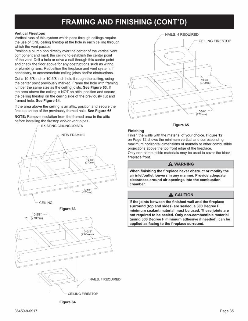
FRAMING AND FINISHING (CONT’D)Vertical FirestopsVertical runs of this system which pass through ceilings require theuseofONEceilingfirestopattheholeineachceilingthroughwhich the vent passes.Position a plumb bob directly over the center of the vertical vent component and mark the ceiling to establish the center point ofthevent.Drillaholeordriveanailthroughthiscenterpointandchecktheflooraboveforanyobstructionssuchaswiringorplumbingruns.Repositionthefireplaceandventsystem,ifnecessary,toaccommodateceilingjoistsand/orobstructions.Cuta10-5/8inchx10-5/8inchholethroughtheceiling,usingthe center point previously marked. Frame the hole with framing lumberthesamesizeastheceilingjoists.See Figure 63. If theareaabovetheceilingisNOTanattic,positionandsecuretheceilingfirestopontheceilingsideofthepreviouslycutandframed hole. See Figure 64. If the area above the ceiling is an attic, position and secure the firestopontopofthepreviouslyframedhole.See Figure 65.NOTE: Remove insulation from the framed area in the attic beforeinstallingthefirestopand/orventpipes.
Figure 63
Figure 64
Figure 65FinishingFinish the walls with the material of your choice. Figure 12 on Page 12 shows the minimum vertical and corresponding maximumhorizontaldimensionsofmantelsorothercombustibleprojectionsabovethetopfrontedgeofthefireplace.Onlynon-combustiblematerialsmaybeusedtocovertheblackfireplacefront.
WARNINGWhen finishing the fireplace never obstruct or modify the air inlet/outlet louvers in any manner. Provide adequate clearances around air openings into the combustion chamber.
CAUTIONIf the joints between the finished wall and the fireplace surround (top and sides) are sealed, a 300 Degree F minimum sealant material must be used. These joints are not required to be sealed. Only non-combustible material (using 300 Degree F minimum adhesive if needed), can be applied as facing to the fireplace surround.

36459-9-0917Page 36
LINER INSTALLATIONNOTE: A liner is required for operation of this fireplace. Refer to the instructions that came with your liner for proper installation.
DVP(48,60)LPZ - Bronze Ridgeback Liner Kit
Figure 66
DVP(48,60)LKR - Black Porcelain Liner Kit
Figure 67

GLASS PLACEMENT
36459-9-0917 Page 37
Preparation of fireplace prior to decorative media placement1. DVLL60BP: The accent glass panels are wrapped and
secured to the burner cover assembly with a cable tie for shipping purposes. Cut the cable tie, then remove and set aside the accent glass panels.
DVLL48BP:TheoptionalLK8accentlightisavailable.Ifused,followinstructionsincludedwiththeLK8lightkitforproper installation
CAUTIONTurnoffallpower to thefireplaceprior tochangingbulbsorservicing the controls.
2. Ifalinerkithasnotbeeninstalled,STOPandinstallonebefore proceeding with media placement.
3. Remove the light cover and verify that the accent light bulbs are installed in the light bracket. These are located in the reflectivelightbracketatthefrontofthefirebox.Useglovesor a soft cloth to verify the light bulbs are plugged correctly. Donothandlehalogenbulbswithyourbarehands.Oilsfromyour skin will cause the bulb to burn out prematurely.
4. Install the two accent glass panels into the metal retainer bracket located above the accent lights. The two glass panels will be placed so they meet together at the center of the bracket.
5. Replace the light cover over the accent lights.6. If applicable, install Logs and Rock kit.
ACCENT LIGHT COVERDO NOT COVER WITHCRUSHED GLASS MEDIA
ACCENT LIGHT GLASS PANELS (DVLL60)ACCENT LIGHT COVER (DVLL48)CRUSHED GLASS MEDIA ALLOWED
BURNER COVERCRUSHED GLASSMEDIA ALLOWED
CAUTION:PLACE CRUSHED
GLASS MEDIA IN THE RECESSEDAREA AROUND THE PILOT, PILOTSENSOR, OR IGNITOR PROBE
DO NOT
Figure 68
7. Add the decorative crushed glass media of your choice at this time. Crushed glass may cover the complete burner cover, accent glass panels, and burner screen.
Place crushed glass media over the burner screen in a single layer.Usejustenoughcrushedglassmediatomasktheburnerscreen(approximately1sq.ft.).Additionalcrushedglassmaybe placed over the burner cover and accent light glass panels as shown in Figure 68. NOTICE: 1/4-inchcrushedglassmediaisrequiredontheburnerscreenandaccentglasspanels.1/4-inchcrushedglassmediaisoptionalontheburnercoverorlightcover(iftheLK8accentlightisnotinstalled.)

36459-9-0917Page 38
MULTIFUNCTION REMOTE OPERATING INSTRUCTIONS
TECHNICAL DATARemote Control
Supplyvoltage 4.5V(three1.5VAAAbatteries)Ambient temperature ratings 0-50°C(32-122°F)Radio frequency 315MHz
WARNINGThe transmitter and receiver are radio frequency devices. Placing the receiver in or near metal may severely reduce the signal range.
WARNINGTurn off the main gas supply and electrical supply to the fireplace during installation and/or maintenance of the receiver device.
WARNINGFIRE HAZARDCan cause severe injury or death. The Receiver causes ignition of the FIREPLACE. The FIREPLACE can turn on suddenly. Keep away from the FIREPLACE burner when operating the remote system or activating manual bypass of the remote system.
CAUTIONPROPERTY DAMAGE HAZARD.Excessive heat can cause property damage. The FIREPLACE can stay lit for many hours. Turn off the FIREPLACE if it is not going to be attended for any length of time. Always place the Transmitter where children can not reach it.
Figure 69
Figure 70
NOTICE: This control system includes a Battery Back-up pack that allows the Fireplace to operate in the event of a power outage.NOTICE: TheAccentLightand/orBlowerfeatureswillnotoperate during a power outage.NOTICE: Replace all Batteries at least once each year, preferably before at the beginning of the season.
CAUTIONFIRE OR EXPLOSION HAZARD. Can cause property damage, sever injury or death. Do not attempt to take apart the gas control or to clean it. Improper assembly and cleaning can cause unreliable operation.

36459-9-0917 Page 39
MULTIFUNCTION REMOTE OPERATING INSTRUCTIONSInitializing the System for the First Time1. Remove the wall cover. Remove cover on the wall mounted
battery back-up holder. See Figure 71. Install the four AA batteries into the wall mounted battery back-up holder then reinstall the cover. See Figure 72.
2. Install three AAA batteries into the battery bay located on the base of the transmitter. See Figure 73.
3. SetthewallremoteslideswitchtotheREMOTEposition.See Figure 72.
4. PressandreleasetheSWIbuttononthewallcontrolwitha paper clip and the IFC module will beep three times to indicatetheIFCmoduleisreadytosynchronizewiththetransmitter within ten seconds. See Figure 72.
Figure 71
SWIBUTTON
Figure 72
5. With the batteries already installed in the Transmitter, pushtheOnbutton.TheReceiverwillbeepfourtimestoindicatetheTransmitter’scommandisacceptedandsetstothe particular code of that Transmitter. The system is now initialized.
Figure 73
Temperature Indication Display °C or °FWiththesystemintheOFFposition,presstheThermostatButtonandtheModeButtonatthesametime.LookattheLCDscreenon the Transmitter to verify that a °C or °F is visible to the right of the Room Temperature display. See Figures 74 and 75.
Figure 74
Figure 75
36459-9-0917Page 40
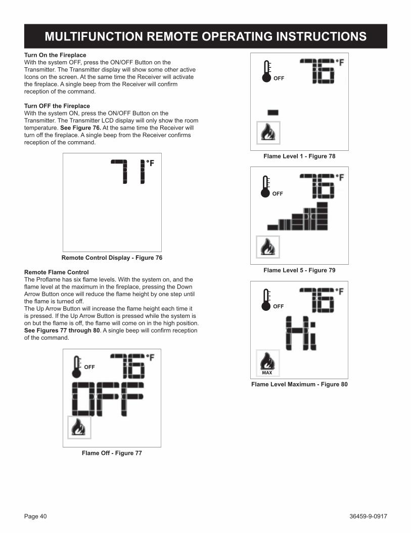
Turn On the FireplaceWiththesystemOFF,presstheON/OFFButtonontheTransmitter. The Transmitter display will show some other active Icons on the screen. At the same time the Receiver will activate thefireplace.AsinglebeepfromtheReceiverwillconfirmreception of the command.
Turn OFF the FireplaceWiththesystemON,presstheON/OFFButtonontheTransmitter.TheTransmitterLCDdisplaywillonlyshowtheroomtemperature. See Figure 76. At the same time the Receiver will turnoffthefireplace.AsinglebeepfromtheReceiverconfirmsreception of the command.
Remote Control Display - Figure 76
Remote Flame ControlTheProflamehassixflamelevels.Withthesystemon,andtheflamelevelatthemaximuminthefireplace,pressingtheDownArrowButtononcewillreducetheflameheightbyonestepuntiltheflameisturnedoff.TheUpArrowButtonwillincreasetheflameheighteachtimeitispressed.IftheUpArrowButtonispressedwhilethesystemisonbuttheflameisoff,theflamewillcomeoninthehighposition.See Figures 77 through 80.Asinglebeepwillconfirmreceptionof the command.
OFF
Flame Off - Figure 77
MULTIFUNCTION REMOTE OPERATING INSTRUCTIONS
OFF
Flame Level 1 - Figure 78
OFF
Flame Level 5 - Figure 79
OFF
Flame Level Maximum - Figure 80

36459-9-0917 Page 41
MULTIFUNCTION REMOTE OPERATING INSTRUCTIONSThe Thermostat Feature may be disabled if desired.Withallthe(3)AAAtypebatteriesinstalled:1. Take out one AAA battery.2. While re-inserting the AAA battery, Push and hold down the thermostat button. This will disable the thermostat feature on the transmitter.
Room Thermostat (Transmitter Operation)The Remote Control can operate as a room thermostat. The thermostat can be set to a desired temperature to control the comfort level in a room. To activate this function, press the Thermostat Button (Figure 70).TheLCDdisplayontheTransmitterwillchangetoshowthattheroomthermostatisONand the set temperature is now displayed. See Figure 81. To adjustthesettemperature,presstheUporDownArrowButtonsuntilthedesiredsettemperatureisdisplayedontheLCDscreenof the Transmitter. See Figure 82.
Figure 81
Figure 82
Smart Thermostat (Transmitter Operation)TheSmartThermostatfunctionadjuststheflameheightinaccordance to the difference between the set point temperature and the actual room temperatures. As the room temperature gets closertothesetpointtheSmartFunctionwillmodulatetheflamedown. To activate this function, press the Thermostat Button until thewordSMARTappearstotherightofthetemperaturebulbgraphic. See Figure 83. To adjust the set temperature, press the UporDownArrowButtonsuntilthedesiredsettemperatureisdisplayedontheLCDscreenoftheTransmitter.See Figure 84.
Note:WhenSmartThermostatisactivated,manualflameheightadjustment is disabled.
Figure 83
Figure 84

36459-9-0917Page 42
Blower Control (Fan)Ifthefireplaceisequippedwithahotaircirculatingfan,thespeedofthefancanbecontrolledbytheProflamesystem.The fan speed can be adjusted through six speeds. To activate this function, use the Mode Button (Figure 70) to index the fan control icon. See Figure 85.UsetheUp/DownArrowButtons(Figure 70) to turn on off or adjust the fan speed. See Figure 86. Asinglebeepwillconfirmreceptionofthecommand.
OFF
Figure 85
OFF
Figure 86
MULTIFUNCTION REMOTE OPERATING INSTRUCTIONSRemote Light Control (Accent Light)Ifthefireplaceisequippedwithaccentlightsbelowthehearth,theintensityofthelightscanbecontrolledbytheProflamesystem.Thelighthasfivelevelsofintensity,plusoff.Toactivatethis function, use the Mode Button (Figure 70) to index the light control icon. See Figure 87. UsetheUp/DownArrowButtons(Figure 70) toturnOn/Off,oradjustthelightintensitylevel.See Figure 88. Asinglebeepwillconfirmreceptionofthecommand.
OFF
Figure 87
OFF
Figure 88

36459-9-0917 Page 43
MULTIFUNCTION REMOTE OPERATING INSTRUCTIONSSplit Flow Control (Option not available for the DVLL60BP Series Fireplaces)Thesecondaryburneriscontrolledbythesplitflow.Toactivatethis function use the Mode Button (Figure 70) to index to the SPLITFLOWmodeicon.See Figures 89 and 90.PressingtheUpArrowButtonwillactivatethesecondaryburner.PressingtheDownArrowButtonwillturnthesecondaryburneroff.Asinglebeepwillconfirmthereceptionofthecommand.
OFF
Figure 89
OFF
Figure 90
Remote Auxiliary Relay Control (optional with this fireplace)TheauxiliaryfunctioncontrolstheAUXrelayoutlet.ToactivatethisfunctionusetheModeButton(Figure 70)toindextotheAUXicon(Figures 91 & 92).PressingtheUpArrowButtonwillactivatetheoutlet.PressingtheDownArrowButtonwillturntheoutletoff.Asinglebeepwillconfirmthereceptionofthecommand.
Figure 91
Figure 92

36459-9-0917Page 44
MULTIFUNCTION REMOTE OPERATING INSTRUCTIONSContinuous Pilot/Intermittent Pilot (CPI/IPI) SelectionWiththesysteminOFFpositionpresstheModeButton(Figure 70) to index to the CPI mode icon. See Figures 93 and 94.PressingtheUpArrowButtonwillactivatetheCPI.PressingtheDownArrowButtonwillreturntoIPI.Asinglebeepwillconfirmthe reception of the command.
OFF
Figure 93
OFF
Figure 94
Button LockThis function will lock the Buttons to avoid unsupervised operation.Toactivatethisfunction,presstheMODEandUPButtonsatthesame time. See Figure 95.Todeactivatethisfunction,presstheMODEandUPButtonsatthe same time.
OFF
Figure 95
Low Battery Power Detection - TransmitterThe life span of the remote control batteries depends on various factors: quality of the batteries used, the number of ignitions of thefireplace,thenumberofchangestotheroomthermostatsetpoint, etc.When the transmitter batteries are low, an Icon will appear on the LCDdisplayofthetransmitterSee Figure 96 before all battery power is lost. When the batteries are replaced this Icon will disappear.
OFF
Figure 96

36459-9-0917 Page 45
Lockout State DefinitionA lockout state is reached when an ignition error occurs. The lockout state will remain set in memory as long as the power supplies are applied.Thiscouldmeanbothananomalousflamedetectionand/ortoomany unsuccessful ignition tries. Thisstateisasafeconditionforthefireplaceandisenteredautomatically by the IFC board. When the IFC board gets into lockout state:1. both the Pilot and the Main Burner solenoids in the gas valve
arede-energized;2. adiagnosticcodeissentthroughthediagnosticredLED.3. the IFC board will ignore any burner ignition command
andremainintheOFFstateunlesstheunlockcommandsequence is met.
The causes of lockout must be investigated under safe conditions bytheuserand/ortheservicepersonnel.To reset the IFC from a lockout state, perform the following procedure: Turningthesystempowersupplies(tothewallcontrolor
remotecontrol)OFFfortwoorthreesecondsandthenrestoring a power supply back on.
The return of the system to normal operation must be checked undersafeconditionsbytheuserand/orservicepersonnel.
Using the Fireplace without a Remote ControlThefireplacecanbeturnedON(HIonly)andOFFwiththewallswitch.ThefireplaceflameON/OFFistheonlyfunctionthatwilloperate;noflameadjustment,lightorblowerwillworkwhenusingthewallswitch.ThewallcontrolswitchshouldbeturnedOFFwhenthefireplaceisnotbeingusedforextendedperiodsoftime.
Battery Backup OperationInstallbatteries(Seeinitializationsequenceonpage69).Incaseofpowerloss,thefireplacewillswitchtobatterymodeautomatically.Thefireplacewilloperatenormallywithoutthefanor light control when in battery mode.
Low Battery DetectionWhen the backup batteries are low, a double-beep will be emitted whenthemodulereceivesanon/offcommand.NocommandswillbeaccepteduntilthebatteriesarereplacedortheA/Cpoweris restored.
MULTIFUNCTION REMOTE OPERATING INSTRUCTIONS

36459-9-0917Page 46
CONTROL SYSTEM TROUBLESHOOTING
PROBLEMOBSERVED POSSIBLECAUSE CORRECTIVEMEASURE
Gasodorduringsetup GasLeak
WHAT TO DO IF YOU SMELL GASDo not try to light any appliance.Do not touch any electrical switch; do not use any phone in your building.Leave the building immediately.Immediately call your gas supplier from a neighbor’s phone. Follow the gas supplier’s instructions.If you cannot reach your gas supplier, call the fire department.
Gasodorbeforefirstignition GasLeak
Fireplace is “on”butnoflameandpilotisnot trying to light
GasLineValveturned“off” Turn shutoff valve to “open” positionControl module in “lockout” Turnfireplace“off” and then back “on”
Pilot continues to spark when pilot is lit.
Notenoughgastopilot WaitforpilotflametostrengthenLowGasPressure Checkpressures.Seepage12.Pilotigniter/sensorisdirty Cleanpilot.Seemaintenancepage79.Pilot not grounded well Check ground connectionsDraftinfirebox Vent restrictor not installedPilot sensor has been bent Replace pilot
Pilot will not ignite, or will not stay lit
Pilotigniter/sensorisdirty Cleanflamesensorandpilotigniter.Seemaintenance page 79.
Pilot not grounded well Check ground connectionsSensorWireloose Check sensor wire terminalsGaspressureincorrect Adjust gas pressurePilotGasLinebentorkinked Replace pilot tubeFaultypilot,Sensorbent Replace PilotFaulty valve Replace Valve
Burner takes too long to fully light
Low gas pressure Check gas supply pressureCloggedordirtycarryover/burnerports Clean portsBlockedorifice CheckorificeopeningFaulty valve Replace valve
Burner does not light but pilot remains on
Low gas pressure Check gas supply pressureClogged or dirty burner ports Clean burner portsBlockedorifice CheckorificeopeningLoose wire connections Checkvalve/controlmoduleconnectionsFaulty pilot Replace pilotFaulty valve Replace valve
Burner lights but does not stay lit while pilot remains on
Low gas pressure Check gas supply pressureLoose sensor wire Check wire connectionFaulty valve Replace valveFaulty pilot or thermocouple ReplaceSafetypilotClogged or dirty burner ports Clean burner ports
(Forfireplaceequippedwithoptionalther-mostatorthermostatremote)Roomtem-perature is higher than thermostat setting
Move(optional)remoteawayfromfire-placeSethighertemperatureon(Optional)remote/thermostat
(Optional)Remotecontrolbatteriesfailing Replace batteries in remote transmitter and receiver

36459-9-0917 Page 47
CONTROL SYSTEM TROUBLESHOOTING (CONT’D)
Burner & pilot light but will not stay lit
Flame sensor dirty Clean pilot sensorLow gas pressure Check gas supply pressureNotenoughfreshairforpilot Opendoororwindow-ventilateClogged or dirty burner ports Clean burner ports
(Forfireplaceequippedwithoptionalther-mostatorthermostatremote)Roomtem-perature is higher than thermostat setting
Move(optional)remoteawayfromfire-placeSethighertemperatureon(Optional)remote/thermostat
(Optional)Remotecontrolbatteriesfailing Replace batteries in remote transmitter and receiver
Faulty pilot or thermocouple Replace pilot
Incorrectburnerflame
Incorrect gas supply or pressure Check gas supply pressureBlockedorifice CheckorificeopeningClogged or dirty burner ports Clean burner portsFaulty valve Replace valveHighaltitude Adjustorificesizeforaltitude
BackfireofburnerBlockedorifice CheckorificeopeningClogged or dirty burner ports Clean burner portsLow gas pressure Check gas supply pressure
Fireplace produces unwanted odorsVapors from paint, hairspray, glue, etc. Ventilateroomuntilodorstops.Donotuse
paint,hairspray,glue,etcaroundfireplaceInitial burn-off of manufacturing chemicals Ventilate room until odor stops
Whistlenoisefromfireplace
Check gas pressure Adjust gas pressure to recommended set-ting.
Air in gas line Bleed linesControl knob not in fully open position OpencontrolknobtofullpositionSpiralgasflexlinepinchedortoosmalldiameter line
Straightenflexlinewherepinchedorre-place gas feed line with larger diameter
PROBLEMOBSERVED POSSIBLECAUSE CORRECTIVEMEASURE

36459-9-0917Page 48
FORYOURSAFETYREADBEFORELIGHTING
A. This appliance must be lighted with the remote control. When lighting the pilot, follow these instructions exactly.
B. BEFORE LIGHTING, smell around the appliance area for gas. Be sure to smell next to the floor because some gas in heavier than air and will settle on the floor.WHAT TO DO IF YOU SMELL GAS
• Do not try to light any appliance.• Do not touch any electrical switch.• Do not use any phone in your building.• Immediately call your gas supplier from a
neighbor's phone. Follow the gas supplier's instructions. If you can not reach your gas supplier, call the fire department.
C. Use only the remote control to operate the valve. Never use tools. If valve does not operate, don't try to repair it, call a qualified service technician. Force or attempted repair may result in a fire or explosion.
D. Do not use this appliance if any part has been underwater. Immediately call a qualified service technician to inspect the appliance and to replace any part of the control system and any gas control which has been underwater.
LIGHTINGINSTRUCTIONS
TOTURNOFFGASTOAPPLIANCE1. Turn off all electric power to the appliance if service is
to be performed (if applicable).2. Locate On/Off gas cock and turn clockwise to
OFF. Do not force.
LIGHTING INSTRUCTIONS
1. STOP! Read the safety information above.2. Turn OFF electric power to the appliance.3. Turn gas cock counterclockwise to ON
position.4. Wait ten minutes to clear out any gas. Then smell for
gas, including near the floor. If you smell gas, STOP! Follow B in the safety information above on this label. If you do not smell gas, go to the next step.
5. Turn ON electric power to the appliance.6. Using the remote control, turn main flame to ON. Refer
to the Multifunction Remote Operating Instructions for more information. If the pilot does not light within 60 seconds, stop and go back to Step 4.
7. Refer to remote control instructions for detailed information, control features, and operation. Note: Refer to Multifunction Remote operating instructions for selection of continuous standing pilot mode or intermittent pilot mode. If the pilot or burner does not stay lit (in the standing pilot mode), stop and immediately call a qualified service technician or gas supplier.
8. If the burner or pilot does not operate properly after several tries, turn the gas control knob clockwise
to OFF and call your service technician or gas supplier.
9. Operation of the gas valve, blower, and/or optional light must be controlled by using the hand held remote control. Refer to remote instructions for detailed operation information.
WARNINGIf you do not follow these instructions exactly, a fire or explosion may result causing property damage, personal injury, or loss of life.

36459-9-0917 Page 49
This page intentionally blank.
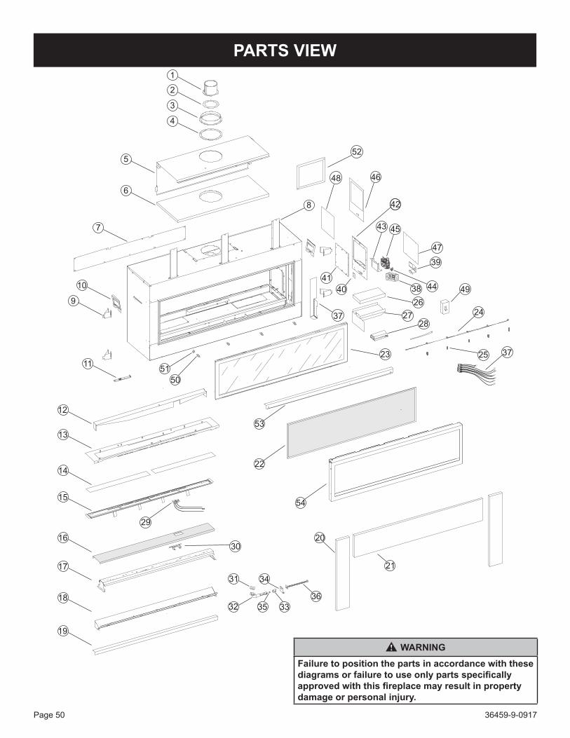
36459-9-0917Page 50
1
2
3
4
5
6
7
8
9
10
11
12
13
14
15
16
17
18
19
31
32 35 33
34
36
29
30
50
51
37
40
42
26
2728
38 44
43 45
47
39
41
23
24
20
21
22
52
4648
25
53
54
49
37
PARTS VIEW
WARNINGFailure to position the parts in accordance with these diagrams or failure to use only parts specifically approved with this fireplace may result in property damage or personal injury.

36459-9-0917 Page 51
PARTS LIST
INDEX NO,
PART NUMBERDESCRIPTION
DVLL48 DVLL601 30975 30975 FlueOutletAssembly2 M170 M170 Gasket,FlueOutlet3 R7567 R7567 Inlet Vent Adaptor - 8-in4 R7573 R7573 Gasket-InletVent5 34431 34431 RearHeatShield6 R11963 R11963 Insulation - Top7 36411 34400 Rear Access Plate
8 33553 33553 Middle Mount Bracket (3Required)
9 28450 28450 NailingFlange(4Required)10 34360 34360 Handle11 35978 35978 DoorLatchTool12 36440 35531 RearBaffle13 36427 34423 Burner Cover Plate14 N/A R11967 AccentGlass(2required)15 36428 34424 GlassSupport16 37065 35658 BurnerScreen17 36429 34426 Burner Assembly Weldment18 N/A 34415 Bracket - Light19 36424 34414 Cover - Light
20 36456 35672 Non-combustibleBoard-Side(2Required)
21 36455 35671 Non-combustibleBoard-Top
22 Q0036 Q0024 ScreenBarrier23 36447 35661 GlassDoorAssembly24 N/A R11888 LightSocketAssembly
25 N/A R10928 LightBulb-35W,GY6.35Base,T3(35WMax)
26 R12081 R12081 Insulation - 1 x 6 x 1227 37093 35498 ControlModuleShield28 R12383 R12383 ControlModule,ProflameII29 R10914 R10914 Pilot-NAT29 R10918 R10918 Pilot - LP30 34425 34425 Pilot Bracket31 R11977 R10933 Gasket-Venturi32 R11978 R10432 VenturiTube-90Degree33 R7624 R7624 AirShutter34 36441 35532 Bracket,OrificeHolder
35 - P280 Orifice#29-Nat35 P209 - Orifice#31-Nat35 - P300 Orifice#48-LP35 P245 - Orifice#50-LP36 R10915 R10915 OrificeHolder-Flexline
37 R11524 R11524 WireHarness,ControlModule
38 R3490 R3490 Junction Box39 27730 27730 Junction Box Mount Bracket40 35530 35530 Bracket-GasLineSeal41 34418 34418 Control Cover - Inner42 34419 34419 Control Plate43 37092 34421 Valve Bracket44 R10882 R10882 Fitting, Inlet 9045 R11233 R11233 Valve-Nat45 R11234 R11234 Valve - LP46 R12085 R12085 Gasket-ControlPlate47 37094 34395 OuterAccessPanel48 R12085 R12085 Gasket,ControlPlate
49 R11584 R11584 Wall Control with Battery Back-Up
50 R8902 R8902 Stud,Spherical(4Required)51 R8866 R8866 Nut,6mmStainlessSteel52 33331 33331 ThimbleSpacer53 36439 35529 ScreenFrameBracket54 36438 35528 ScreenFrameNS R11522 R11522 Remote TransmitterNS R11584 R11584 BatteryHolderBoxNS 37107 NA RightSideLinerNS 37106 NA LeftSideLinerNS 37105 NA RearSideLiner
NS R11552 R1155210ft.ExtensionWireHarness(Controlmoduletowallbox)
NS-NotShown
INDEX NO.
PART NUMBERDESCRIPTION
DVLL48 DVLL60

36459-9-0917Page 52
COMPONENT WIRING DIAGRAM
Ifanyoftheoriginalwireassuppliedwiththisfireplacemustbe replaced, it must be replaced with equivalent gauge and temperature rated wire.
Thisfireplaceisonlyforusewiththetypeofgasindicatedon the rating plate and may be installed in an aftermarket, permanentlylocated,manufactured(mobile)homewherenotprohibitedbylocalcodes.Thisfireplaceisnotconvertibleforusewithothergases,unlessacertifiedkitisused.
WARNINGELECTRICAL GROUNDING INSTRUCTIONSThis fireplace is equipped with a three-prong grounding plug for your protection against shock hazard and should be plugged directly into a properly grounded three-prong receptacle. Do not cut or remove the grounding prong from this plug.
CAUTIONLabel all wires prior to disconnection when servicing controls. Wiring errors can cause improper and dangerous operation.
CAUTIONDo not operate the fireplace with glass panel removed, cracked or broken. Replacement of the panel should be done by a licensed qualified service person.
WARNINGImproper installation, adjustment, alteration, service or maintenance can cause property damage, personal injury or loss of life. Installation and service must be performed by a qualified installer, service agency or the gas supplier.
Verify proper operation after servicing.
NL
COMBUSTION
BLOWER
ORANGE
PILOT
GAS CONTROL VALVE
ORANGEGREEN
YELLOW
WHITEOR
BLACK
BLACKWHITE
BLOWER
FU
SE
BLACKWHITE
GREEN
POWER CORD
TO JUNCTION
BOX
AUX.
LOOP
TO LIGHTS
SLE
EV
E
USER INTERFACE/
BATTERY HOLDER
ORANGE
WHITE
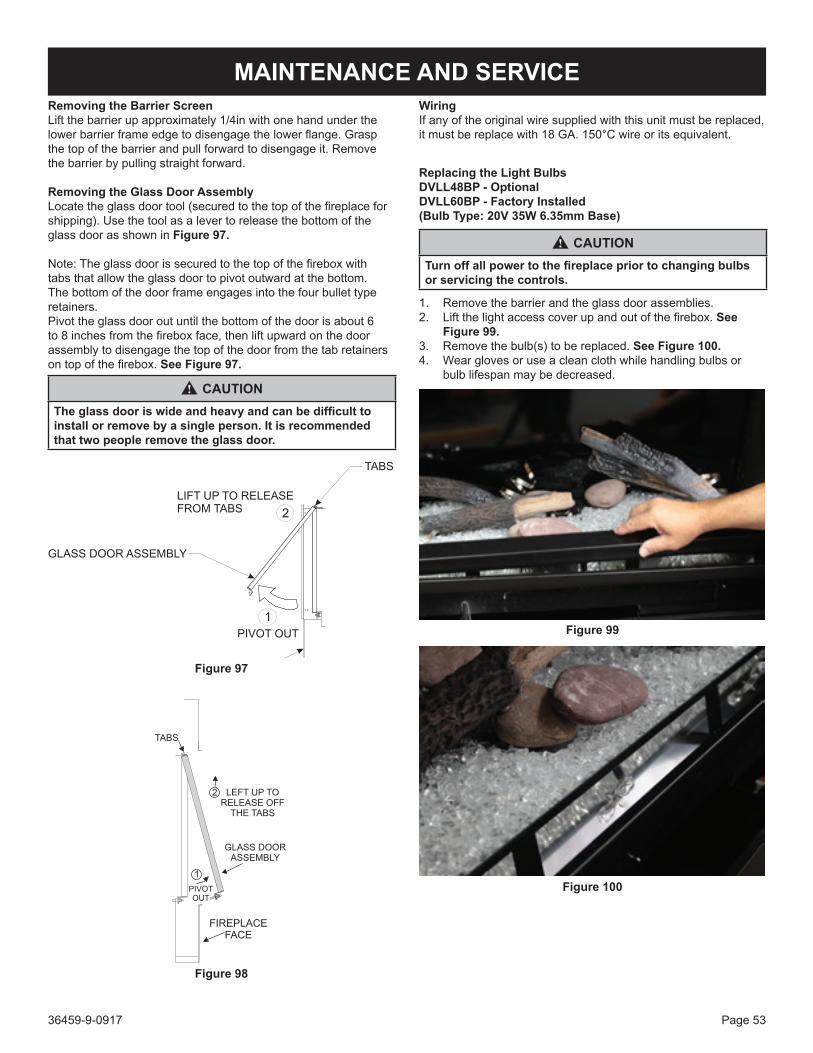
36459-9-0917 Page 53
MAINTENANCE AND SERVICERemoving the Barrier ScreenLiftthebarrierupapproximately1/4inwithonehandunderthelowerbarrierframeedgetodisengagethelowerflange.Graspthe top of the barrier and pull forward to disengage it. Remove the barrier by pulling straight forward.
Removing the Glass Door AssemblyLocatetheglassdoortool(securedtothetopofthefireplaceforshipping).Usethetoolasalevertoreleasethebottomoftheglass door as shown in Figure 97.
Note:Theglassdoorissecuredtothetopofthefireboxwithtabs that allow the glass door to pivot outward at the bottom. The bottom of the door frame engages into the four bullet type retainers.Pivot the glass door out until the bottom of the door is about 6 to8inchesfromthefireboxface,thenliftupwardonthedoorassembly to disengage the top of the door from the tab retainers ontopofthefirebox.See Figure 97.
CAUTIONThe glass door is wide and heavy and can be difficult to install or remove by a single person. It is recommended that two people remove the glass door.
LIFT UP TO RELEASEFROM TABS
TABS
1
2
FIREPLACE FACE
PIVOT OUT
GLASS DOOR ASSEMBLY
Figure 97
PIVOTOUT
TABS
2 LEFT UP TORELEASE OFF
THE TABS
GLASS DOORASSEMBLY
FIREPLACEFACE
1
Figure 98
WiringIf any of the original wire supplied with this unit must be replaced, itmustbereplacewith18GA.150°Cwireoritsequivalent.
Replacing the Light Bulbs DVLL48BP - OptionalDVLL60BP - Factory Installed(Bulb Type: 20V 35W 6.35mm Base)
CAUTIONTurn off all power to the fireplace prior to changing bulbs or servicing the controls.
1. Remove the barrier and the glass door assemblies.2. Liftthelightaccesscoverupandoutofthefirebox.See
Figure 99.3. Removethebulb(s)tobereplaced. See Figure 100.4. Wear gloves or use a clean cloth while handling bulbs or
bulb lifespan may be decreased.
Figure 99
Figure 100

36459-9-0917Page 54
MAINTENANCE AND SERVICE (CONT’D)GAS VALVE AND CONTROL ACCESS INSTRUCTIONS
CAUTIONSharp Edges! Use gloves and eye protection when servic-ing the fireplace controls.
NOTICE: To service or inspect the gas valve and control system after the fireplace has been installed, or if there is no right side outer accessibility, follow these steps for servicing the fireplace gas control valve.Accessing the Gas ValveAlwaysturnoffgasandelectricalsupplytothefireplacebeforeservicing the controls.1. Remove the barrier screen and glass door assemblies and
set them aside in a safe location.2. It is not necessary to remove decorative glass media from
the burner cover or accent glass panels to gain access to the valve compartment.
3. Remove the front light cover. Lift the cover up and out of the fireplaceandsetasideinasafelocation.
Figure 101
4. If the Logs and Rock kit or the Ridgeback Liner is installed, thesemustberemovedfromthefireplace.Refertotheinstructions supplied with these options for removal and installation. If the porcelain liner is installed, only the right sidelinermustberemoved.Removethe5/16inhex-headscrew at the top rear of the right side panel. Pull forward on the right side liner to release it from the front retainer bracket and set aside in a safe location.
5. Removethetwelve5/16inhex-headscrewsthatsecuretheaccesscoverplateontherightsideofthefirebox.See Figure 102.
Figure 102
6. The gas valve is now accessible for checking inlet and outlet gaspressures,flexlineconnections,andwiringtothevalve.See Figure 103. Figure 104 shows the inlet and outlet gas test ports.
Figure 103
Figure 104
7. Toreplaceofthegasvalvebyremovingthetwo5/16inhex-head screws on top of the gas control bracket. The gas valve andbracketcanbelifteduptogainaccesstotheflexlineconnections.

36459-9-0917 Page 55
MAINTENANCE AND SERVICE (CONT’D)ACCESSING THE CONTROL MODULEAlwaysturnoffgasandelectricalsupplytothefireplacebeforeservicing the controls.1. Remove the barrier screen and glass door assemblies, and
set them aside in a safe location.2. It is not necessary to remove decorative glass media from
the burner cover or accent glass panels to gain access to the control module.
3. The control module is in the lower front corner of the fireplacebottom.ItissecuredtothefireplacewithVelcro.The gas control and accent light wiring is routed through the lower right side opening to the gas valve and accent light wireconnectionsinthefirebox.The120Vpowercordisrouted through the lower right side opening and plugged into the Junction Box receptacle. See Figure 105.
Figure 105
MAINTENANCEMaintenance frequency must be determined individually for each application.Someconsiderationsare:• Exposuretowater,dirt,chemicalsandheatcandamagethe
gas control and shut down the control system.• Cyclingfrequency.Fireplacesthatmaycycle20,000times
annually should be checked monthly.• Intermittentuse.Fireplacesthatareusedseasonallyshould
be checked before shutdown and again before the next use.• Dusty,wetorcorrosiveenvironment.Becausethese
environments can cause the gas control to deteriorate more rapidly, the system should be checked more often.
• Anycontrolshouldbereplacedifitdoesnotperformproperlyon checkout or service. In addition, replace any module if it is wet or looks like it has been wet.
SERVICEDonotdisassemblethegascontrol;itcontainsnon-replaceablecomponents. Attempted disassembly or repair can damage the control.Exactlyfollowthewarningsandthelightinginstructions.1. Beforelighting,smellaroundthefireplaceareaforgas.If
thefireplaceusesLP(bottled)gas,besuretosmellnexttothefloorbecauseLPgasisheavierthanair.Ifyousmellgas, immediately shut off the manual valve in the gas piping tothefireplaceoronLPatthetank.Donottrytolightanyappliance.Donottouchanyelectricalswitchorusethephone. Leave the building and call your gas supplier. If your gassuppliercannotbereached,callthefiredepartment.
2. Thegascontrolmustbereplacedifithasbeenfloodedwithwater.Callaqualifiedservicetechnician.
3. The gas control is a safety device. It must be replaced in case of any physical damage such as bent terminals, missing parts, stripped threads, or evidence of exposure to excessive heat.
Follow the operating instructions provided by the manufacturer of your appliance.
NOTEItisnormalforfireplacesfabricatedofsteeltogiveoffsomeexpansionand/orcontractionnoiseduringthestartuporcooldowncycle.Similarnoisesarefoundwithyourfurnaceheatexchanger or car engine.
Itisnormalforyourgasfireplacetogiveoffsomeodorthefirsttime it is burned. This is due to the curing of the paint and oil from the manufacturing process.
Please ensure that your room is well ventilated - open a window.
Burn your fireplace for at least one hour the first time you use it. If optional fan kit has been installed, place fan in the OFF position during this time.IMPORTANT: Turnoffgasbeforeservicingfireplace.Haveaqualifiedservicepersonperformthesecheck-upsonceayearpreferablybeforetheusingofthefireplace.• Clean Burner and Control Compartment Keepthecontrolcompartmentandburnerareacleanby
vacuuming or brushing at least twice a year.Cleaning Procedure1. Turnofffireplace.2. Removethebarrierscreenandglassdoorassembly.See
GlassDoorRemoval.3. Removedecorativemedia(acleanportableshop-vacis
recommended).4. Vacuum burner cover and burner screen areas. The control
module located in the bottom front corner can also be vacuumed off.
5. Replace decorative media.6. Reinstall the glass door and barrier screen.7. Ignitefireplace.SeeLightingInstructions.8. Ifflameappearsabnormal,callaserviceperson.

36459-9-0917Page 56
• Check Vent System Thefireplaceandventingsystemshouldbeinspectedbeforeinitialuseandatleastannuallybyaqualifiedserviceperson.Inspect the external vent cap on a regular basis to make sure thatnodebrisisinterferingwiththeairflow.
Glass CleaningClean the glass before use and two or three times each heating season.Duringstart-upcondensation(whichisnormal)formsonthe inside of the glass and causes lint, dust and other airborne particles to cling to the glass surface. Also initial paint curing may depositaslightfilmontheglass.Useanon-abrasivehouseholdcleanerandwarmwater(werecommendgasfireplaceglasscleaner).General Glass Information
WARNINGDo not operate fireplace with the glass front removed, cracked or broken.
Onlyglassapprovedforusebythemanufacturerinfireplacemaybe used for replacement. The glass replacement should be done byalicensedorqualifiedserviceperson.
WARNING1. The use of substitute glass will void all product warranties.2. Care must be taken to avoid breakage of the glass.3. Under no circumstances should this fireplace be operated
without the glass front or with a broken glass front. Replacement of the glass (with gasket) as supplied by the manufacturer should be done by a qualified service person.
4. Do not abuse the glass by striking or hitting it.
WARNINGDo not use Ammonia based or abrasive cleaners on glass. Do not attempt to clean glass when glass is hot.
MAINTENANCE AND SERVICEGlass Door and Barrier Screen Removal and ReplacementRefer to page 53 for removal of the barrier screen and glass door assemblies.Refer to the Parts View and Parts List on pages 50 and 51 to identify replacement parts such as the barrier screen and glass door assemblies.
Glass Door InstallationRefer to Figure 98 to install the glass door assembly. Because of the width of the door assembly, it is recommended that two peopleinstallit.Holdthedooratananglesothebottomisabout8inchesfromthefireplaceface.Engagethetopslotsintodoorframewiththetabslocatedatthetopofthefirebox.Gentlypivotthe door inward to align the four bullet catches across the bottom ofthedoorframe.Oncethebulletpinsarealignedwiththespringcatches on the door frame, push the bottom of the door inward to engage the spring catches with the bullet pins.
Barrier InstallationThe barrier screen assembly is installed onto the glass door assemblywithoutfasteners.Thetopflangeofthebarrierengagesthetopofthedoorframeandthebottomflange.Thebottomflangeonthebarrierwillbeinsertedbetweentheglassdoor frame across the bottom. Adjust the barrier left to right to center it.
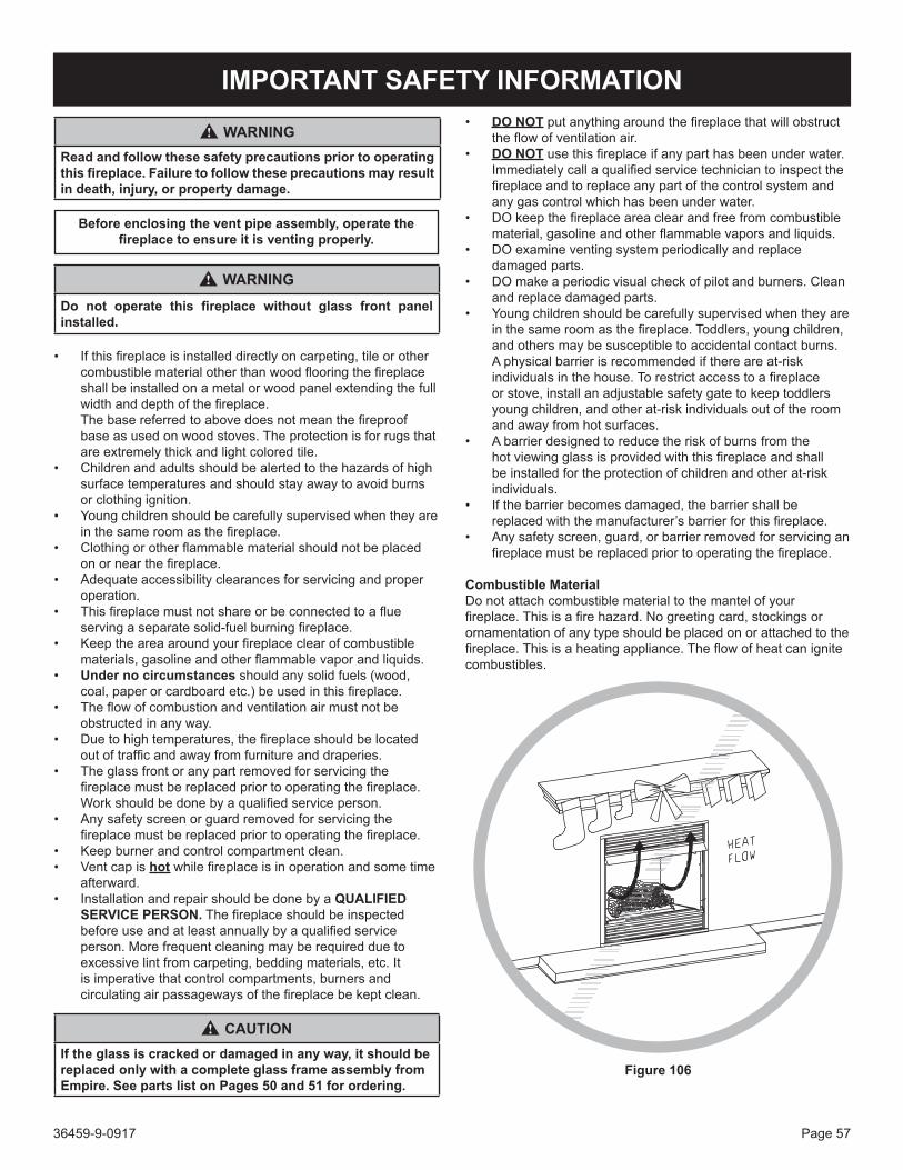
36459-9-0917 Page 57
IMPORTANT SAFETY INFORMATION
WARNINGRead and follow these safety precautions prior to operating this fireplace. Failure to follow these precautions may result in death, injury, or property damage.
Before enclosing the vent pipe assembly, operate the fireplace to ensure it is venting properly.
WARNING
Do not operate this fireplace without glass front panel installed.
• Ifthisfireplaceisinstalleddirectlyoncarpeting,tileorothercombustiblematerialotherthanwoodflooringthefireplaceshall be installed on a metal or wood panel extending the full widthanddepthofthefireplace.
Thebasereferredtoabovedoesnotmeanthefireproofbase as used on wood stoves. The protection is for rugs that are extremely thick and light colored tile.
• Childrenandadultsshouldbealertedtothehazardsofhighsurface temperatures and should stay away to avoid burns or clothing ignition.
• Youngchildrenshouldbecarefullysupervisedwhentheyareinthesameroomasthefireplace.
• Clothingorotherflammablematerialshouldnotbeplacedonornearthefireplace.
• Adequateaccessibilityclearancesforservicingandproperoperation.
• Thisfireplacemustnotshareorbeconnectedtoaflueservingaseparatesolid-fuelburningfireplace.
• Keeptheareaaroundyourfireplaceclearofcombustiblematerials,gasolineandotherflammablevaporandliquids.
• Under no circumstancesshouldanysolidfuels(wood,coal,paperorcardboardetc.)beusedinthisfireplace.
• Theflowofcombustionandventilationairmustnotbeobstructed in any way.
• Duetohightemperatures,thefireplaceshouldbelocatedoutoftrafficandawayfromfurnitureanddraperies.
• Theglassfrontoranypartremovedforservicingthefireplacemustbereplacedpriortooperatingthefireplace.Workshouldbedonebyaqualifiedserviceperson.
• Anysafetyscreenorguardremovedforservicingthefireplacemustbereplacedpriortooperatingthefireplace.
• Keepburnerandcontrolcompartmentclean.• Ventcapishotwhilefireplaceisinoperationandsometime
afterward.• Installation and repair should be done by a QUALIFIED
SERVICE PERSON. Thefireplaceshouldbeinspectedbeforeuseandatleastannuallybyaqualifiedserviceperson. More frequent cleaning may be required due to excessive lint from carpeting, bedding materials, etc. It is imperative that control compartments, burners and circulatingairpassagewaysofthefireplacebekeptclean.
CAUTIONIf the glass is cracked or damaged in any way, it should be replaced only with a complete glass frame assembly from Empire. See parts list on Pages 50 and 51 for ordering.
• DO NOT putanythingaroundthefireplacethatwillobstructtheflowofventilationair.
• DO NOT usethisfireplaceifanyparthasbeenunderwater.Immediatelycallaqualifiedservicetechniciantoinspectthefireplaceandtoreplaceanypartofthecontrolsystemandany gas control which has been under water.
• DOkeepthefireplaceareaclearandfreefromcombustiblematerial,gasolineandotherflammablevaporsandliquids.
• DO examine venting system periodically and replace damaged parts.
• DOmake a periodic visual check of pilot and burners. Clean and replace damaged parts.
• Youngchildrenshouldbecarefullysupervisedwhentheyareinthesameroomasthefireplace.Toddlers,youngchildren,and others may be susceptible to accidental contact burns. A physical barrier is recommended if there are at-risk individualsinthehouse.Torestrictaccesstoafireplaceor stove, install an adjustable safety gate to keep toddlers young children, and other at-risk individuals out of the room and away from hot surfaces.
• Abarrierdesignedtoreducetheriskofburnsfromthehotviewingglassisprovidedwiththisfireplaceandshallbe installed for the protection of children and other at-risk individuals.
• Ifthebarrierbecomesdamaged,thebarriershallbereplacedwiththemanufacturer’sbarrierforthisfireplace.
• Anysafetyscreen,guard,orbarrierremovedforservicinganfireplacemustbereplacedpriortooperatingthefireplace.
Combustible MaterialDonotattachcombustiblematerialtothemantelofyourfireplace.Thisisafirehazard.Nogreetingcard,stockingsorornamentation of any type should be placed on or attached to the fireplace.Thisisaheatingappliance.Theflowofheatcanignitecombustibles.
Figure 106

36459-9-0917Page 58
SAFETY INFORMATION FOR USERS OF LP GASPropane (LP-Gas) is a flammable gas which can cause fires and explosions. In its natural state, propane is odorless and colorless. You may not know all the following safety precautions which can protect both you and your family from an accident. Read them carefully now, then review them point by point with the members of your household. Someday when there may not be a minute to lose, everyone’s safety will depend on knowing exactly what to do. If, after reading the following information, you feel you still need more information, please contact your gas supplier.
LP-GAS WARNING ODOR
If a gas leak happens, you should be able to smell the gas because of the odorant put in the LP-Gas. That’s your signal to go into immediate action!
• Donotoperateelectricswitches,lightmatches,useyourphone.Donotdoanythingthatcouldignitethegas.
• Geteveryoneoutofthebuilding,vehicle,trailer,orarea.DothatIMMEDIATELY.
• Closeallgastankorcylindersupplyvalves.• LP-Gasisheavierthanairandmaysettleinlowareassuch
as basements. When you have reason to suspect a gas leak, keepoutofbasementsandotherlowareas.Stayoutuntilfirefightersdeclarethemtobesafe.
• Useyourneighbor’sphoneandcallatrainedLP-Gasservicepersonandthefiredepartment.Eventhoughyoumaynotcontinuetosmellgas,donotturnonthegasagain.Donotre-enter the building, vehicle, trailer, or area.
• Finally,lettheservicemanandfirefighterscheckforescapedgas.Havethemairouttheareabeforeyoureturn.ProperlytrainedLP-Gasservicepeopleshouldrepairtheleak,thencheckandrelightthegasfireplaceforyou.
NO ODOR DETECTED - ODOR FADESome people cannot smell well. Some people cannot smell the odor of the chemical put into the gas. You must find out if you can smell the odorant in propane.Smokingcandecrease your ability to smell. Being around an odor for a time canaffectyoursensitivityorabilitytodetectthatodor.Sometimesother odors in the area mask the gas odor. People may not smell the gas odor or their minds are on something else. Thinking about smelling a gas odor can make it easier to smell.The odorant in LP-Gas is colorless, and it can fade under some circumstances. For example, if there is an underground leak,themovementofthegasthroughsoilcanfiltertheodorant.OdorantsinLP-Gasalsoaresubjecttooxidation.Thisfadingcanoccur if there is rust inside the storage tank or in iron gas pipes.
The odorant in escaped gas can adsorb or absorb onto or into walls, masonry and other materials and fabrics in a room. That will take some of the odorant out of the gas, reducing its odor intensity.LP-Gasmaystratifyinaclosedarea,andtheodorintensitycouldvaryatdifferentlevels.Sinceitisheavierthanair,theremaybemore odor at lower levels. Always be sensitive to the slightest gas odor. If you detect any odor, treat it as a serious leak. Immediately go into action as instructed earlier.
SOME POINTS TO REMEMBER• Learn to recognize the odor of LP-Gas.YourlocalLP-Gas
Dealercangiveyoua“ScratchandSniff”pamphlet.Useittofindoutwhatthepropaneodorsmellslike.IfyoususpectthatyourLP-Gashasaweakorabnormalodor,callyourLP-GasDealer.
• Ifyouarenotqualified,donotlightpilotlights,performservice,ormakeadjustmentstoappliancesontheLP-Gassystem.Ifyouarequalified,consciouslythinkabouttheodorofLP-Gaspriortoandwhilelightingpilotlightsorperformingservice or making adjustments.
• Sometimesabasementoraclosed-uphousehasamustysmellthatcancoveruptheLP-Gasodor.Donottrytolightpilot lights, perform service, or make adjustments in an area where the conditions are such that you may not detect the odoriftherehasbeenaleakofLP-Gas.
• Odorfade,duetooxidationbyrustoradsorptiononwallsof new cylinders and tanks, is possible. Therefore, people should be particularly alert and careful when new tanks or cylindersareplacedinservice.Odorfadecanoccurinnewtanks,orreinstalledoldtanks,iftheyarefilledandallowedtosettoolongbeforerefilling.Cylindersandtankswhichhave been out of service for a time may develop internal rust which will cause odor fade. If such conditions are suspected to exist, a periodic sniff test of the gas is advisable. If you have any question about the gas odor, call your LP-Gas dealer. A periodic sniff test of the LP-Gas is a good safety measure under any condition.
• If,atanytime,youdonotsmelltheLP-Gasodorantandyou think you should, assume you have a leak. Then take the same immediate action recommended above for the occasionwhenyoudodetecttheodorizedLP-Gas.
• Ifyouexperienceacomplete“gasout,”(thecontainerisundernovaporpressure),turnthetankvalveoffimmediately. If the container valve is left on, the container may draw in some air through openings such as pilot light orifices.Ifthisoccurs,somenewinternalrustingcouldoccur.If the valve is left open, then treat the container as a new tank. Always be sure your container is under vapor pressure by turning it off at the container before it goes completely emptyorhavingitrefilledbeforeitiscompletelyempty.

36459-9-0917 Page 59
REQUIREMENTS FOR MASSACHUSETTSForallsidewallhorizontallyventedgasfueledequipmentinstalled in every dwelling, building or structure used in whole or in part for residential purposes, including those owned or operated by the Commonwealth and where the side wall exhaust ventterminationislessthansevenfeetabovefinishedgradeinthe area of the venting, including but not limited to decks and porches,thefollowingrequirementsshallbesatisfied:
1. INSTALLATIONOFCARBONMONOXIDEDETECTORS.Atthetimeofinstallationofthesidewallhorizontalventedgasfueledequipment,theinstallingplumberorgasfittershallobserve that a hard wired carbon monoxide detector with analarmandbatteryback-upisinstalledonthefloorlevelwhere the gas equipment is to be installed. In addition, the installingplumberorgasfittershallobservethatabatteryoperated or hard wired carbon monoxide detector with an alarm is installed on each additional level of the dwelling, buildingorstructureservedbythesidewallhorizontalvented gas fueled equipment. It shall be the responsibility ofthepropertyownertosecuretheservicesofqualifiedlicensed professionals for the installation of hard wired carbon monoxide detectors
a. Intheeventthatthesidewallhorizontallyventedgasfueled equipment is installed in a crawl space or an attic, the hard wired carbon monoxide detector with alarm and battery back-up may be installed on the next adjacent floorlevel.
b. In the event that the requirements of this subdivision can not be met at the time of completion of installation, the owner shall have a period of thirty days to comply with the above requirements; provided, however, that during said thirty day period, a battery operated carbon monoxide detector with an alarm shall be installed.
2. APPROVEDCARBONMONOXIDEDETECTORS.Eachcarbon monoxide detector as required in accordance with theaboveprovisionsshallcomplywithNFPA720andbeANSI/UL2034listedandIAScertified.
3. SIGNAGE.Ametalorplasticidentificationplateshallbepermanently mounted to the exterior of the building at a minimum height of eight feet above grade directly in line with theexhaustventterminationforthehorizontallyventedgasfueled appliance or equipment. The sign shall read, in print sizenolessthan1/2inchinsize,“GAS VENT DIRECTLY BELOW. KEEP CLEAR OF ALL OBSTRUCTIONS”.
4. INSPECTION.Thestateorlocalgasinspectorofthesidewallhorizontallyventedgasfueledequipmentshallnot approve the installation unless, upon inspection, the inspector observes carbon monoxide detectors and signage installed in accordance with the provisions of 248 CMR 5.08(2)(a)1through4.
(b) EXEMPTIONS:Thefollowingequipmentisexemptfrom248CMR5.08(2)(a)1through4:
1. The equipment listed in Chapter 10 entitled “EquipmentNotRequiredToBeVented”inthemostcurrenteditionofNFPA54asadoptedbytheBoard; and
2. ProductApprovedsidewallhorizontallyventedgasfueled equipment installed in a room or structure separate from the dwelling, building or structure used in whole or in part for residential purposes.
(d) MANUFACTURERREQUIREMENTS-GASEQUIPMENTVENTINGSYSTEMNOTPROVIDED.When the manufacturer of a Product Approved side wallhorizontallyventedgasfueledequipmentdoesnotprovidethepartsforventingthefluegases,butidentifies“specialventingsystems”,thefollowingrequirementsshallbesatisfiedbythemanufacturer:
1. Thereferenced“specialventingsystem”instructions shall be included with the appliance or equipment installation instructions; and
2. The“specialventingsystems”shallbeProductApproved by the Board, and the instructions for that system shall include a parts list and detailed installation instruction.
(e) AcopyofallinstallationinstructionsforallProductApprovedsidewallhorizontallyventedgasfueledequipment, all venting instructions, all parts lists forventinginstructions,and/orallventingdesigninstructions shall remain with the appliance or equipment at the completion of the installation.

36459-9-0917Page 60
FIREPLACE SERVICE HISTORYDate Dealer Name Service Technician Name Service Performed/Notes

36459-9-0917 Page 61
FIREPLACE SERVICE HISTORYDate Dealer Name Service Technician Name Service Performed/Notes

36459-9-0917Page 62
ToOrderPartsUnderWarranty,pleasecontactyourlocalEmpiredealer.Seethedealerlocatoratwww.empirecomfort.com.To provide warranty service, your dealer will need your name and address, purchase date and serial number, and the nature of the problem with the unit. ToOrderPartsAftertheWarrantyPeriod,pleasecontactyourdealeroroneoftheMasterPartsDistributorslistedbelow.This list changes from time to time. For the current list, please click on the Master Parts button at www.empirecomfort.com.Please note: Master Parts Distributors are independent businesses that stock the most commonly ordered OriginalEquipmentrepairpartsforHeaters,Grills,andFireplacesmanufacturedbyEmpireComfortSystemsInc.
MASTER PARTS DISTRIBUTOR LIST
Parts Not Under WarrantyPartscanbeorderedthroughyourServicePerson,Dealer,oraMasterPartsDistributor.SeethispagefortheMasterPartsDistribu-tors list. For best results, the service person or dealer should order parts through the distributor. Parts can be shipped directly to the service person/dealer.Warranty PartsWarrantypartswillneedaproofofpurchaseandcanbeorderedbyyourServicePersonorDealer.Proofofpurchaseisrequired for warranty parts.AllpartslistedinthePartsListhaveaPartNumber.Whenorderingparts,firstobtaintheModelNumberandSerialNumberfromthenameplateonyourequipment.ThendeterminethePartNumber(nottheIndexNumber)andtheDescriptionofeachpartfromthefol-lowing illustration and part list. Be sure to give all this information . . .
FireplaceModelNumber PartDescription
FireplaceSerialNumber PartNumber
TypeofGas(PropaneorNatural)
Donotorderbolts,screws,washersornuts.Theyarestandardhardwareitemsandcanbepurchasedatanylocalhardwarestore.Shipmentscontingentuponstrikes,firesandallcausesbeyondourcontrol.
HOW TO ORDER REPAIR PARTS
Dey Distributing1401 Willow Lake BoulevardVadnaisHeights,MN55101
Phone: 651-490-9191Toll Free: 800-397-1339Website: www.deydistributing.comParts: Heater, Hearth and Grills
F. W. Webb Company200LocustStreetHartford,CT06114
Phone: 860-722-2433Toll Free: 800-243-9360Fax: 860-293-0479Toll Free Fax: 800-274-2004Websites: www.fwwebb.com & www.victormfg.comParts: Heater, Hearth and Grills
East Coast Energy Products10EastRoute36WestLongBranch,NJ07764
Phone: 732-870-8809Toll Free: 800-755-8809Fax: 732-870-8811Website: www.eastcoastenergy.comParts: Heater, Hearth and Grills

36459-9-0917 Page 63
EmpireComfortSystemsInc.warrantiesthishearthproducttobefreefromdefectsatthetimeofpurchaseandfortheperiodsspecifiedbelow.Hearthproductsmustbeinstalledbyaqualifiedtechnicianandmustbemaintainedandoperatedsafely,inaccordancewiththeinstructionsintheowner’smanual.EmpirewillnotwarrantyanyChâteau,Boulevard,orMantisfireplacethatisnotinstalledbythesellingdealerorthatdealer’sdirectcontractagents.Thiswarrantyappliestotheoriginalpurchaseronlyandisnottransferable.Allwarrantyrepairsmustbeaccomplishedbyaqualifiedgasappliancetechnician.
Limited Lifetime Parts Warranty – Combustion Chamber, Heat Exchanger, and Factory-Installed Glass Ifthecombustionchamber,heatexchanger(seepartslist)orfactory-installedglassfailsbecauseofdefective
workmanshipormaterial,EmpirewillrepairorreplaceatEmpire’soption.Limited Three-Year Parts Warranty – All Other Components (Except Remote Controls, Thermostats, Accessories and Replacement Parts)
Shouldanypartfailbecauseofdefectiveworkmanshipormaterialwithinthreeyearsfromthedateofpurchase, EmpirewillrepairorreplaceatEmpire’soption.Limited One-Year Parts Warranty – Remote Controls, Thermostats, Accessories, and Parts
Shouldanyremotecontrol,thermostat,accessory,orotherpartfailbecauseofdefectiveworkmanshipwithinone yearfromthedateofpurchase,EmpirewillrepairorreplaceatEmpire’soption.
Duties of the Owner Theappliancemustbeinstalledbyaqualifiedinstallerandoperatedinaccordancewiththeinstructionsfurnished with the appliance. A bill of sale, cancelled check, or payment record should be kept to verify purchase date and establish warranty period. Ready access to the appliance for service.
What Is Not Covered Damagesthatmightresultfromtheuse,misuse,orimproperinstallationofthisappliance. Travel, diagnostic costs and freight charges on warranted parts to and from the factory. Claims that do not involve defective workmanship or materials. Unauthorizedserviceorpartsreplacements. Removal and reinstallation cost. Inoperable due to improper or lack of maintenance.
How To Get Service To make a claim under this warranty, please have your receipt available and contact your installing dealer. Providethedealerwiththemodelnumber,serialnumber,typeofgas,andpurchaseverification.Theinstalling dealer is responsible for providing service and will contact the factory to initiate any warranted parts replacements. Empirewillmakereplacementpartsavailableatthefactory.Shippingexpensesarenotcovered. If,aftercontactingyourEmpiredealer,servicereceivedhasnotbeensatisfactory,contact:Consumer RelationsDepartment,EmpireComfortSystemsInc.,POBox529,Belleville,Illinois62222,orsendane-mailto [email protected]“ConsumerRelations”inthesubjectline.
Your Rights Under State Law Thiswarrantygivesyouspecificlegalrights,andyoumayalsohaveotherrights,whichvaryfromstatetostate.
WARRANTY

www.empirecomfort.com
Empire Comfort Systems Inc.Belleville, ILIf you have a general question about our products, please e-mail us at [email protected]. If you have a service or repair question, please contact your dealer.