Installation Instructions Alfa Romeo 147автоотопитель.рф/manual/Alfa...
28
WARNING! Hazard warning: Incorrect installation or repair of Webasto heating systems may cause a fire or result in the emission of carbon monoxide, which can be fatal. Serious or fatal injuries can be caused as a result. Specialist company training, technical documentation, specialized tools and equipment are required to install and repair Webasto heating and cooling systems. NEVER attempt to install or repair Webasto heating or cooling systems if you have not successfully completed the company training and thereby acquired the required technical skills, or if you do not have access to the required technical documentation, tools and equipment needed to carry out correct installation and repairs. ALWAYS follow all Webasto installation and repair instructions and observe all warnings. Webasto does not accept any liability for defects and damage that are attributable to installation by untrained staff. Water Heater Unit Installation Instructions Ident. No.:1313160A_EN Fee Euro 10.00 © Webasto AG Alfa Romeo 147 Gasoline and Diesel from Model Year 2001 Left-hand drive vehicle not for JTD 16V not with GTA Feel the drive Thermo Top E Additional Heater e1 00 0003 Thermo Top C Additional Heater e1 00 0002
Transcript of Installation Instructions Alfa Romeo 147автоотопитель.рф/manual/Alfa...
WARNING!
Hazard warning:
Incorrect installation or repair of Webasto heating systems may cause a fire or result in the emission of carbon monoxide, which can be fatal. Serious or fatal injuries can be caused as a result.
Specialist company training, technical documentation, specialized tools and equipment are required to install and repair Webasto heating and cooling systems.
NEVER attempt to install or repair Webasto heating or cooling systems if you have not successfully completed the company training and thereby acquired the required technical skills, or if you do not have access to the required technical documentation, tools and equipment needed to carry out correct installation and repairs.
ALWAYS follow all Webasto installation and repair instructions and observe all warnings.
Webasto does not accept any liability for defects and damage that are attributable to installation by untrained staff.
Water Heater Unit
Installation Instructions
Ident. No.:1313160A_EN Fee Euro 10.00 © Webasto AG
Alfa Romeo 147 Gasoline and Dieselfrom Model Year 2001Left-hand drive vehiclenot for JTD 16Vnot with GTA
Feel the drive
Thermo Top E Additional Heatere1
00 0003
Thermo Top C Additional Heatere1
00 0002
Alfa Romeo 147
Table of Contents
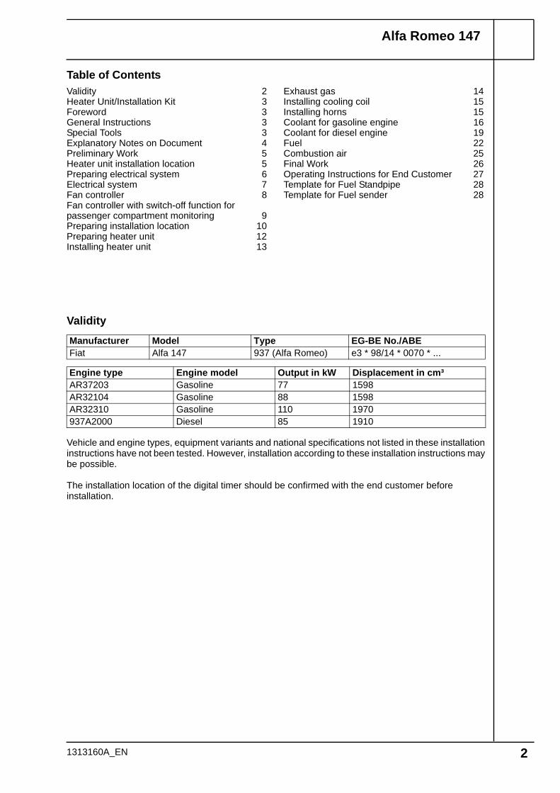
Validity
Vehicle and engine types, equipment variants and national specifications not listed in these installation instructions have not been tested. However, installation according to these installation instructions may be possible.
The installation location of the digital timer should be confirmed with the end customer before installation.
Manufacturer Model Type EG-BE No./ABEFiat Alfa 147 937 (Alfa Romeo) e3 * 98/14 * 0070 * ...
Engine type Engine model Output in kW Displacement in cm³AR37203 Gasoline 77 1598AR32104 Gasoline 88 1598AR32310 Gasoline 110 1970937A2000 Diesel 85 1910
Validity 2Heater Unit/Installation Kit 3Foreword 3General Instructions 3Special Tools 3Explanatory Notes on Document 4Preliminary Work 5Heater unit installation location 5Preparing electrical system 6Electrical system 7Fan controller 8Fan controller with switch-off function for passenger compartment monitoring 9Preparing installation location 10Preparing heater unit 12Installing heater unit 13
Exhaust gas 14Installing cooling coil 15Installing horns 15Coolant for gasoline engine 16Coolant for diesel engine 19Fuel 22Combustion air 25Final Work 26Operating Instructions for End Customer 27Template for Fuel Standpipe 28Template for Fuel sender 28
1313160A_EN 2
Alfa Romeo 147
Heater Unit/Installation Kit
ForewordThese installation instructions apply to Alfa Romeo 147 Gasoline and Diesel vehicles - for validity, see page 2 - from model year 2001 and later, assuming technical modifications to the vehicle do not affect installation, any liability claims excluded. Depending on the vehicle version and equipment, modifications may be necessary during installation with respect to these installation instructions.
However, the stipulations in the "installation instructions" and "operating and maintenance instructions" for the Thermo Top C/E must always be observed.The corresponding rules of technology and any information from the vehicle manufacturer should be observed during the installation work.
General InstructionsInstallation should be carried out according to the general, standard rules of technology. Unless specified otherwise, fasten hoses, lines and wiring harnesses to original vehicle lines and wiring harnesses using cable ties.Sharp edges should be fitted with edge protectors (split-open plastic hose).Spray unfinished body areas, e.g. drilled holes, with anti-corrosion wax (Tectyl 100K, Order No. 111329).
Special Tools- Torque wrench for 2.0 - 10 Nm- Hose clamping pliers
Quantity Description Order No.:1 Retail Accessories for Thermo Top E Gasoline See price listor1 Retail Accessories for Thermo Top E Diesel See price listor1 Retail Accessories for Thermo Top C Gasoline See price listor1 Retail Accessories for Thermo Top C Diesel See price listand1 Installation kit for Alfa Romeo 147 Gasoline and Diesel 1313097A
1313160A_EN 3
Alfa Romeo 147
Explanatory Notes on Document
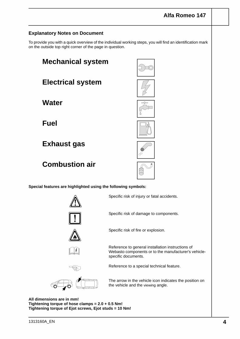
To provide you with a quick overview of the individual working steps, you will find an identification mark on the outside top right corner of the page in question.
1313160A_EN 4
Special features are highlighted using the following symbols:
The arrow in the vehicle icon indicates the position on the vehicle and the viewing angle.
Specific risk of injury or fatal accidents.
Specific risk of damage to components.
Specific risk of fire or explosion.
Reference to general installation instructions of Webasto components or to the manufacturer's vehicle-specific documents.
Reference to a special technical feature.
All dimensions are in mm!Tightening torque of hose clamps = 2.0 + 0.5 Nm!Tightening torque of Ejot screws, Ejot studs = 10 Nm!
Mechanical system
Electrical system
Water
Fuel
Exhaust gas
Combustion air
Alfa Romeo 147
Preliminary Work
WARNING!
- Open fuel tank cap, ventilate tank.- Close the tank cap again.- Disconnect the battery "earth" or "ground" connection.- Depressurize the cooling system.- Copy the factory number from the original type label to the duplicate type label.- Remove years that do not apply from the duplicate label.- Attach the duplicate label (type label) in the appropriate place.- Remove the engine cover on the left.- Remove the coolant reservoir cap on the right.- Remove the complete intake hose.- Disconnect the expansion tank and lay it aside.- Expose the distributor B1 in the engine compartment.- Remove the right-hand wheel well trim.- Remove bumper- Remove the horns.- Remove the horn cable up from the wiring harness sleeve up to the frame side member.- Insulate the horn cable and route it under the right-hand headlight.- Remove the underride protection.- Remove the trim of the fuel lines on the underbody.- Remove the lighting unit for the passenger compartment (only with passenger compartment
monitoring).- Remove the rear bench seat (only for gasoline vehicles).- Open the tank-fitting service lid (only for gasoline vehicles).- Remove the fuel-tank sending unit according to the manufacturer's instructions (only for gasoline
vehicles).
Remove page 27 "Operating Instructions for End Customer" and add to the vehicle operating instructions.
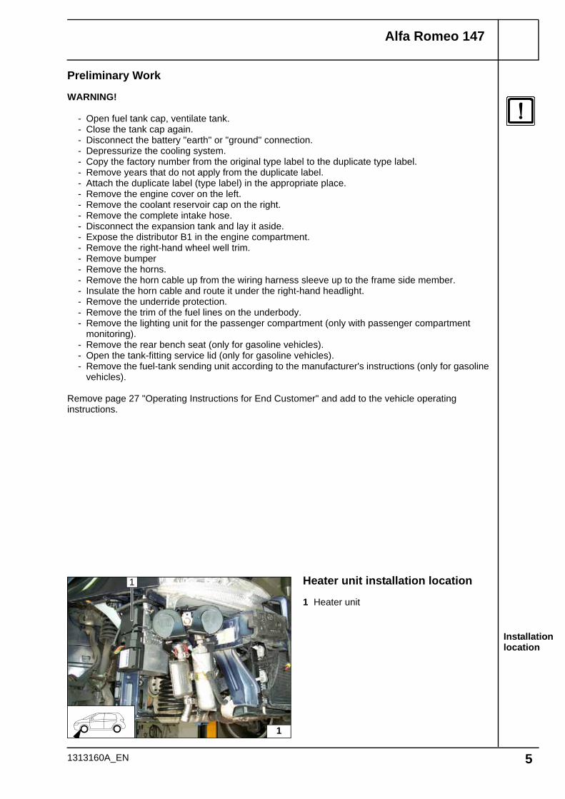
Installation location
Heater unit installation location
1 Heater unit
1
1
1313160A_EN 5
Alfa Romeo 147
Cutting out insulation
Bending perforated bracket
Preparing K3
PreparingK3.1
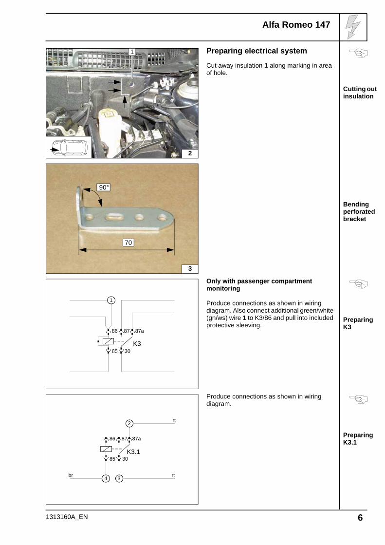
Preparing electrical system
Cut away insulation 1 along marking in area of hole.
Only with passenger compartment monitoring
Produce connections as shown in wiring diagram. Also connect additional green/white (gn/ws) wire 1 to K3/86 and pull into included protective sleeving.
Produce connections as shown in wiring diagram.
1
2
70
90°
3
86
85 30
87a87
K3
1
86
85 30
87a87
K3.1
2
34br rt
rt
1313160A_EN 6
Alfa Romeo 147
Wiring harness installation diagram
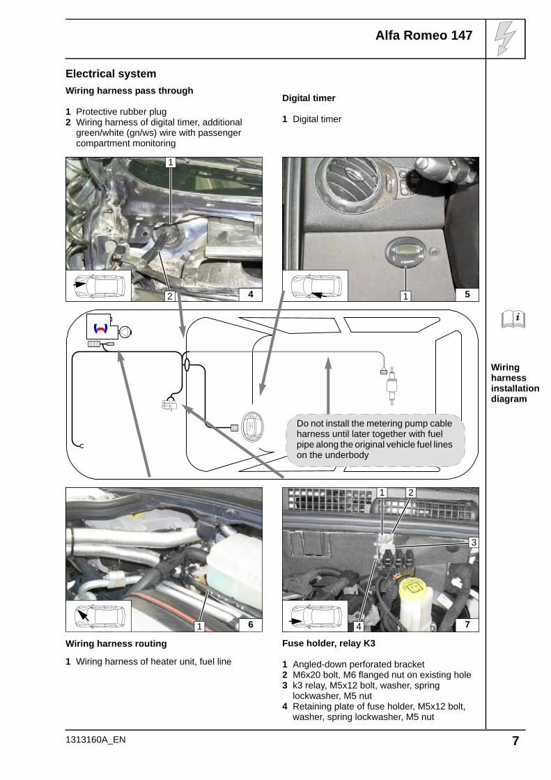
Electrical systemWiring harness pass through
1 Protective rubber plug2 Wiring harness of digital timer, additional
green/white (gn/ws) wire with passenger compartment monitoring
Digital timer
1 Digital timer
Wiring harness routing
1 Wiring harness of heater unit, fuel line
Fuse holder, relay K3
1 Angled-down perforated bracket2 M6x20 bolt, M6 flanged nut on existing hole3 k3 relay, M5x12 bolt, washer, spring
lockwasher, M5 nut4 Retaining plate of fuse holder, M5x12 bolt,
washer, spring lockwasher, M5 nut
4
1
2 51
Do not install the metering pump cable harness until later together with fuel pipe along the original vehicle fuel lines on the underbody
61 74
21
3
1313160A_EN 7
Alfa Romeo 147
Wiring diagram
Legend
Connect-ing fan-mo-tor
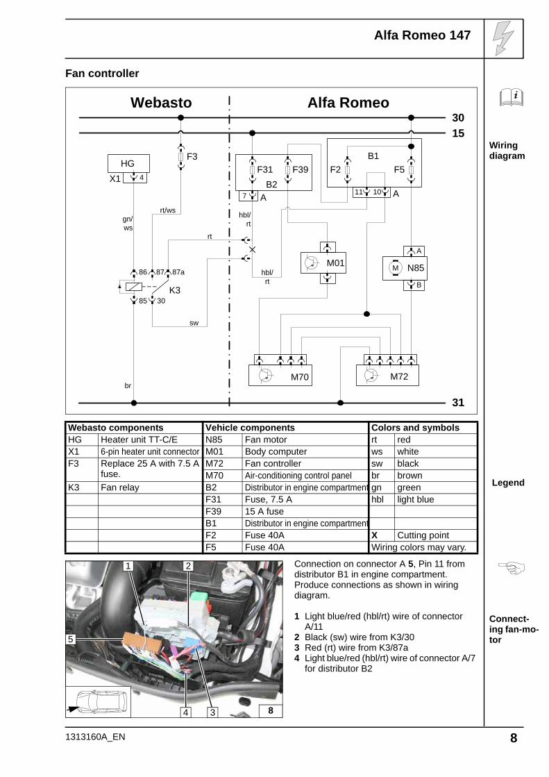
Fan controller
Webasto components Vehicle components Colors and symbolsHG Heater unit TT-C/E N85 Fan motor rt redX1 6-pin heater unit connector M01 Body computer ws whiteF3 Replace 25 A with 7.5 A
fuse.M72 Fan controller sw blackM70 Air-conditioning control panel br brown
K3 Fan relay B2 Distributor in engine compartment gn greenF31 Fuse, 7.5 A hbl light blueF39 15 A fuseB1 Distributor in engine compartmentF2 Fuse 40A X Cutting pointF5 Fuse 40A Wiring colors may vary.
Connection on connector A 5, Pin 11 from distributor B1 in engine compartment.Produce connections as shown in wiring diagram.
1 Light blue/red (hbl/rt) wire of connector A/11
2 Black (sw) wire from K3/303 Red (rt) wire from K3/87a4 Light blue/red (hbl/rt) wire of connector A/7
for distributor B2
Webasto
31
3015
Alfa Romeo
F3
86
85 30
87a87
K3
HGX1 4
F31B2
7 A
M70
A
B
N85M
B1
A1011
F2 F5
M72
rt
sw
hbl/rt
hbl/rt
rt/wsgn/ws
br
F39
M01
8
1
4
5
2
3
1313160A_EN 8
Alfa Romeo 147
Wiring diagram
Legend
Switching off passen-ger com-partment monitoring
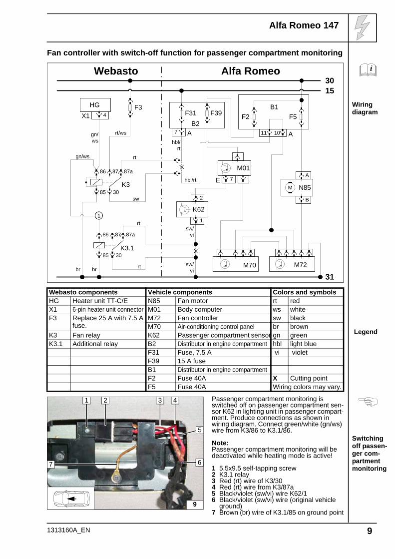
Fan controller with switch-off function for passenger compartment monitoring
Webasto components Vehicle components Colors and symbolsHG Heater unit TT-C/E N85 Fan motor rt redX1 6-pin heater unit connector M01 Body computer ws whiteF3 Replace 25 A with 7.5 A
fuse.M72 Fan controller sw blackM70 Air-conditioning control panel br brown
K3 Fan relay K62 Passenger compartment sensor gn greenK3.1 Additional relay B2 Distributor in engine compartment hbl light blue
F31 Fuse, 7.5 A vi violetF39 15 A fuseB1 Distributor in engine compartmentF2 Fuse 40A X Cutting pointF5 Fuse 40A Wiring colors may vary.
Passenger compartment monitoring is switched off on passenger compartment sen-sor K62 in lighting unit in passenger compart-ment. Produce connections as shown in wiring diagram. Connect green/white (gn/ws) wire from K3/86 to K3.1/86.
Note:Passenger compartment monitoring will be deactivated while heating mode is active!
1 5.5x9.5 self-tapping screw2 K3.1 relay3 Red (rt) wire of K3/304 Red (rt) wire from K3/87a5 Black/violet (sw/vi) wire K62/16 Black/violet (sw/vi) wire (original vehicle
ground)7 Brown (br) wire of K3.1/85 on ground point
Webasto
31
3015
Alfa Romeo
F3
86
85 30
87a87
K3
HGX1 4
A
B
N85M
B1
A1011
F2 F5
M72
rt
sw
hbl/rt
hbl/rt
rt/wsgn/ws
br
86
85 30
87a87
K3.1
K621
2
F31B2
7 A
F39
M70
gn/ws
br
sw/vi
sw/vi
rt
rt
1
M017E
9
2
67
1
5
3 4
1313160A_EN 9
Alfa Romeo 147
Detaching plastic bracket
Removing plastic bracket
Copying hole pattern
Holes in cross member
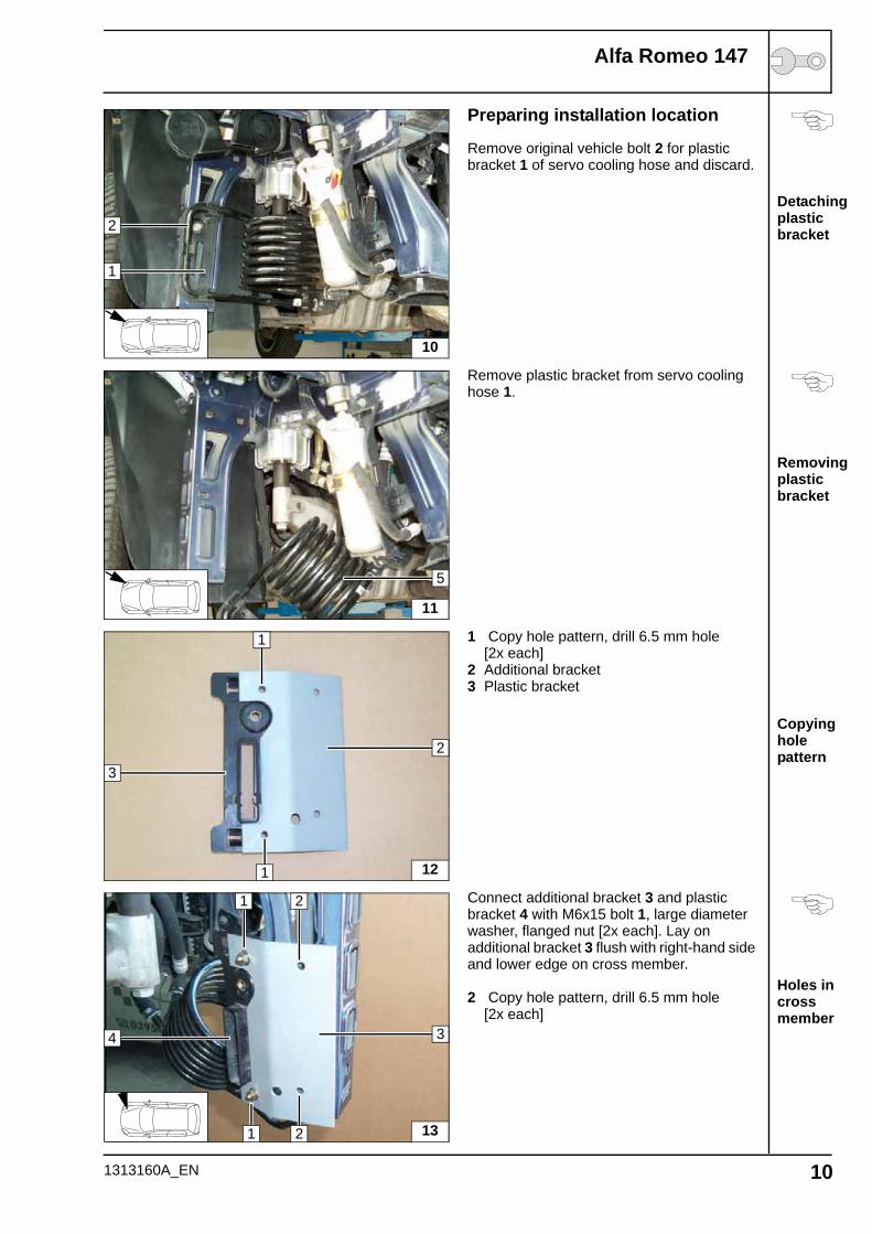
Preparing installation location
Remove original vehicle bolt 2 for plastic bracket 1 of servo cooling hose and discard.
Remove plastic bracket from servo cooling hose 1.
1 Copy hole pattern, drill 6.5 mm hole [2x each]
2 Additional bracket3 Plastic bracket
Connect additional bracket 3 and plastic bracket 4 with M6x15 bolt 1, large diameter washer, flanged nut [2x each]. Lay on additional bracket 3 flush with right-hand side and lower edge on cross member.
2 Copy hole pattern, drill 6.5 mm hole [2x each]
2
1
10
11
5
12
2
1
1
3
13
3
1 2
1
4
2
1313160A_EN 10
Alfa Romeo 147
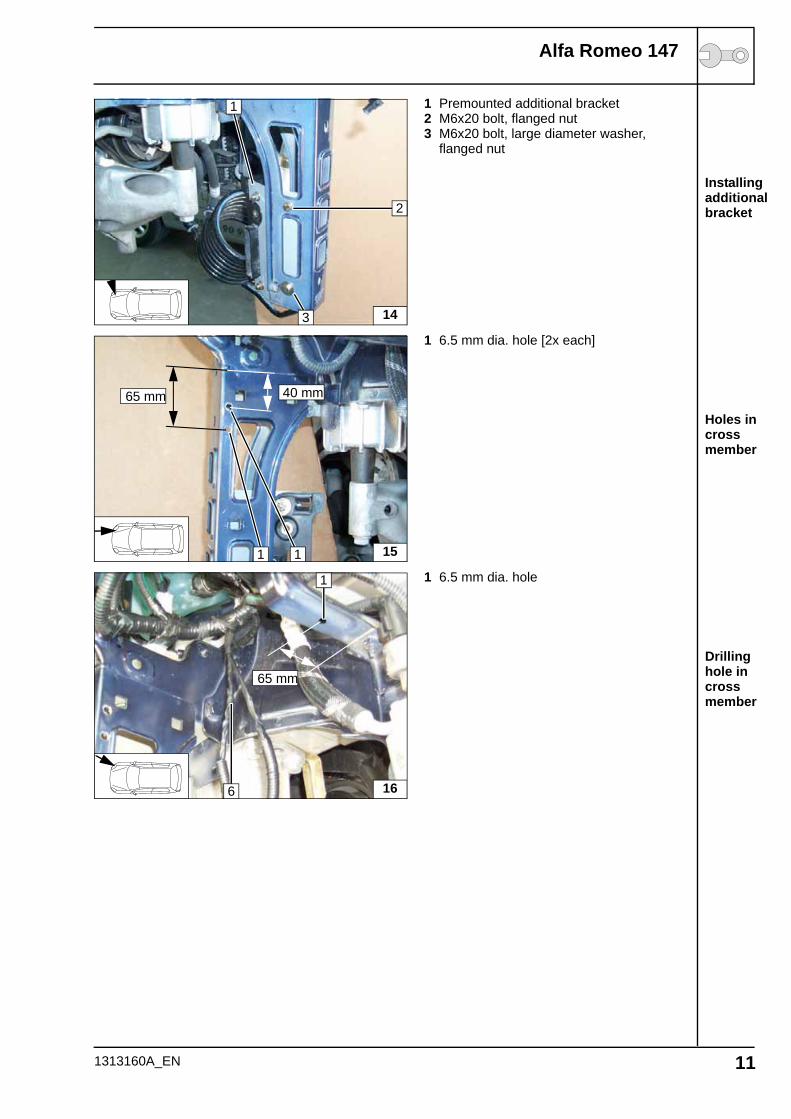
Installing additional bracket
Holes in cross member
Drilling hole in cross member
1 Premounted additional bracket2 M6x20 bolt, flanged nut3 M6x20 bolt, large diameter washer,
flanged nut
1 6.5 mm dia. hole [2x each]
1 6.5 mm dia. hole
14
2
3
1
151
65 mm 40 mm
1
16
1
6
65 mm
1313160A_EN 11
Alfa Romeo 147
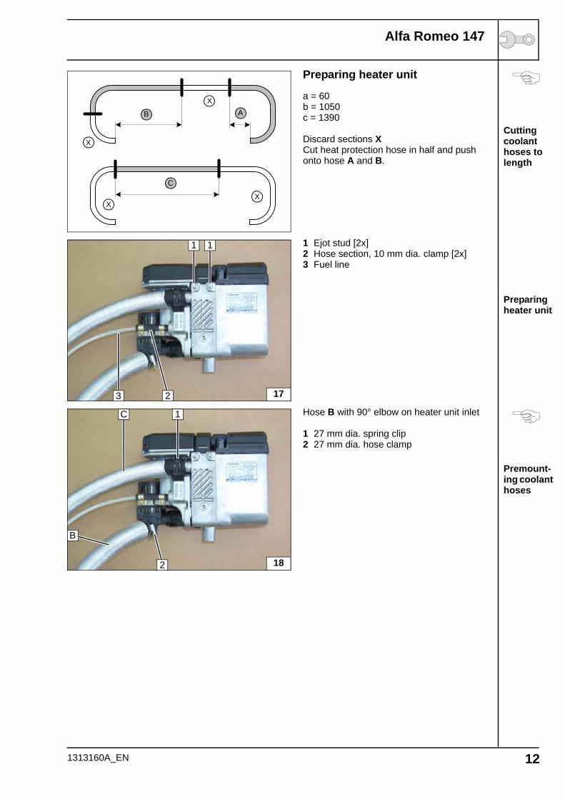
Cutting coolant hoses to length
Preparing heater unit
Premount-ing coolant hoses
Preparing heater unit
a = 60b = 1050c = 1390
Discard sections XCut heat protection hose in half and push onto hose A and B.
1 Ejot stud [2x]2 Hose section, 10 mm dia. clamp [2x]3 Fuel line
Hose B with 90° elbow on heater unit inlet
1 27 mm dia. spring clip2 27 mm dia. hose clamp
C
XX
B
XA
X
1 1
23 17
1C
B
2 18
1313160A_EN 12
Alfa Romeo 147
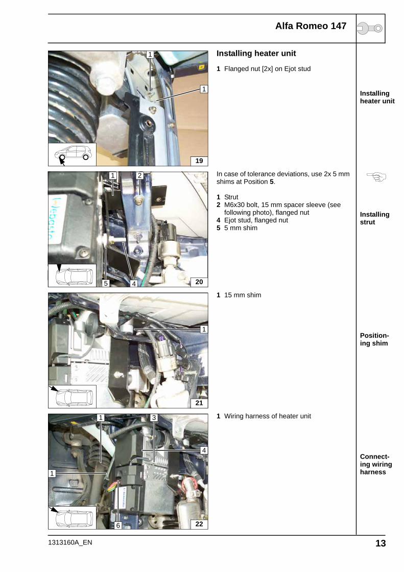
Installing heater unit
Installing strut
Position-ing shim
Connect-ing wiring harness
Installing heater unit
1 Flanged nut [2x] on Ejot stud
In case of tolerance deviations, use 2x 5 mm shims at Position 5.
1 Strut2 M6x30 bolt, 15 mm spacer sleeve (see
following photo), flanged nut4 Ejot stud, flanged nut5 5 mm shim
1 15 mm shim
1 Wiring harness of heater unit
19
1
1
20
1
5
2
4
21
1
22
4
1
6
3
1
1313160A_EN 13
Alfa Romeo 147
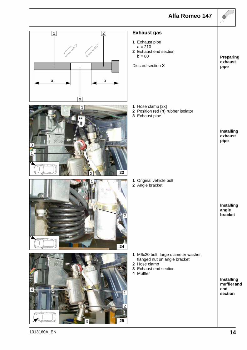
Preparing exhaust pipe
Installing exhaust pipe
Installing angle bracket
Installing muffler and end section
Exhaust gas
1 Exhaust pipea = 210
2 Exhaust end sectionb = 80
Discard section X
1 Hose clamp [2x]2 Position red (rt) rubber isolator3 Exhaust pipe
1 Original vehicle bolt2 Angle bracket
1 M6x20 bolt, large diameter washer, flanged nut on angle bracket
2 Hose clamp3 Exhaust end section4 Muffler
a b
1 2
X
23
1
2
1
3
2
1
24
1
3
2
4
25
1313160A_EN 14
Alfa Romeo 147
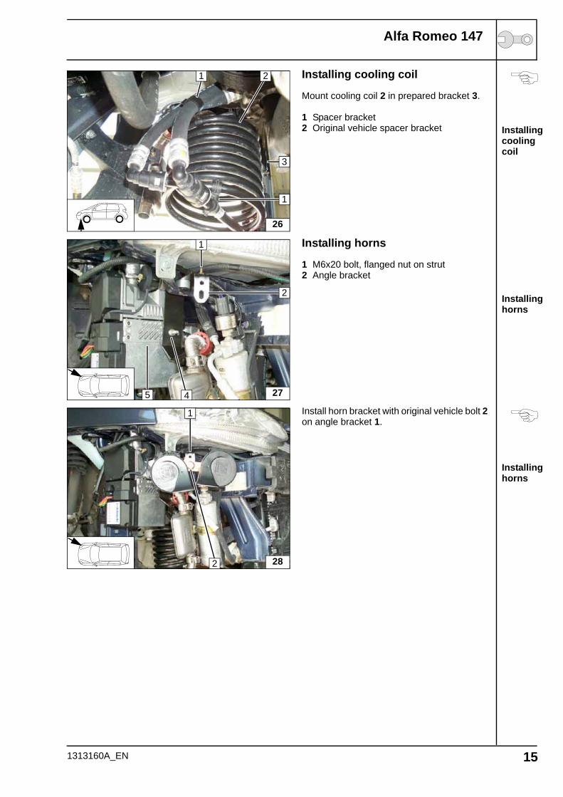
Installing cooling coil
Installing horns
Installing horns
Installing cooling coil
Mount cooling coil 2 in prepared bracket 3.
1 Spacer bracket2 Original vehicle spacer bracket
Installing horns
1 M6x20 bolt, flanged nut on strut2 Angle bracket
Install horn bracket with original vehicle bolt 2 on angle bracket 1.
26
1 2
1
3
275
1
4
2
28
1
2
1313160A_EN 15
Alfa Romeo 147
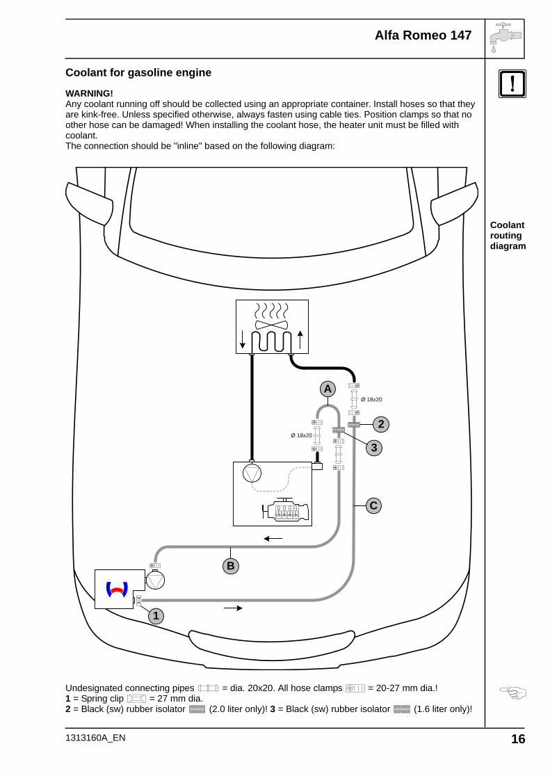
Coolant routing diagram
Coolant for gasoline engine
WARNING!Any coolant running off should be collected using an appropriate container. Install hoses so that they are kink-free. Unless specified otherwise, always fasten using cable ties. Position clamps so that no other hose can be damaged! When installing the coolant hose, the heater unit must be filled with coolant.The connection should be "inline" based on the following diagram:
Undesignated connecting pipes = dia. 20x20. All hose clamps = 20-27 mm dia.!1 = Spring clip = 27 mm dia.2 = Black (sw) rubber isolator (2.0 liter only)! 3 = Black (sw) rubber isolator (1.6 liter only)!
A
B
C
1
Ø 18x20
Ø 18x20
2
3
1313160A_EN 16
Alfa Romeo 147
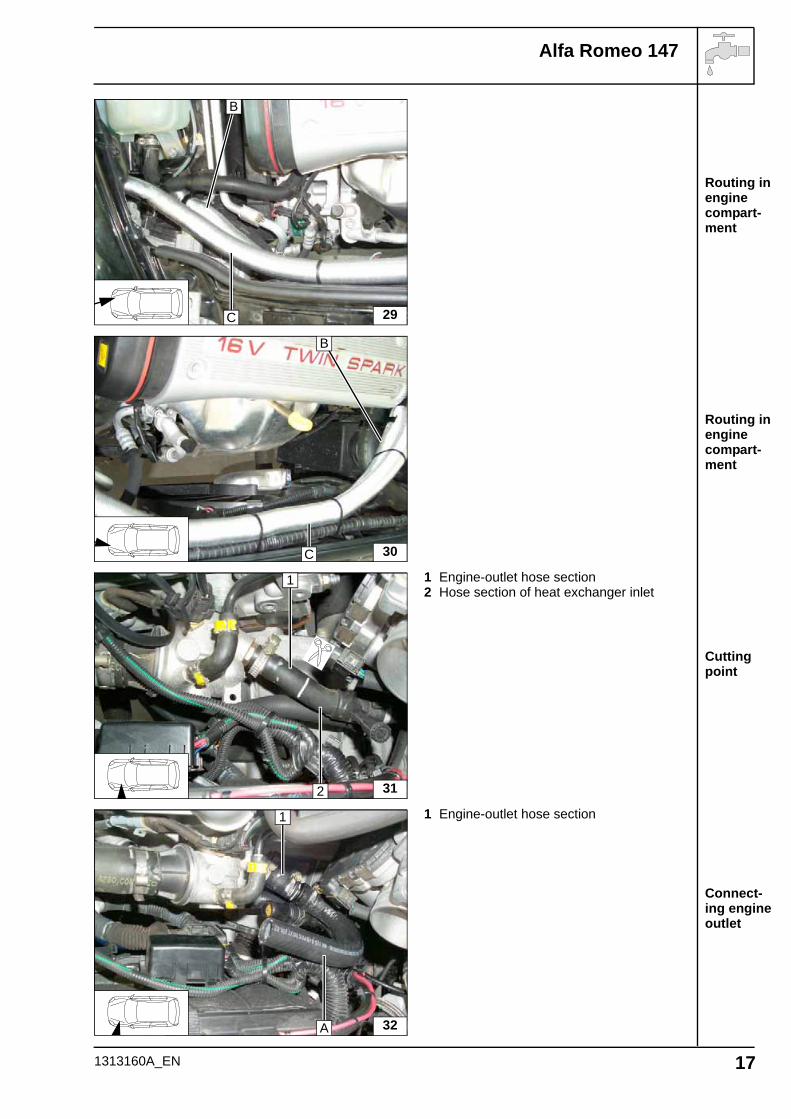
Routing in engine compart-ment
Routing in engine compart-ment
Cutting point
Connect-ing engine outlet
1 Engine-outlet hose section2 Hose section of heat exchanger inlet
1 Engine-outlet hose section
29
B
C
30
B
C
312
1
32
1
A
1313160A_EN 17
Alfa Romeo 147
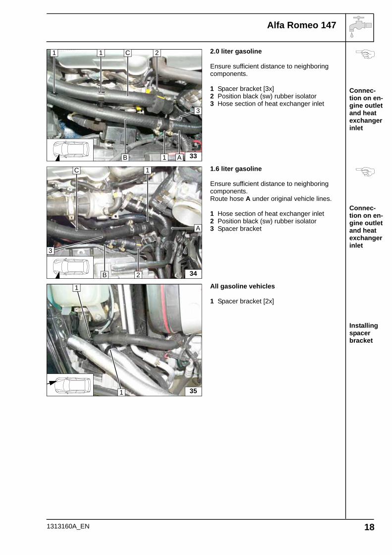
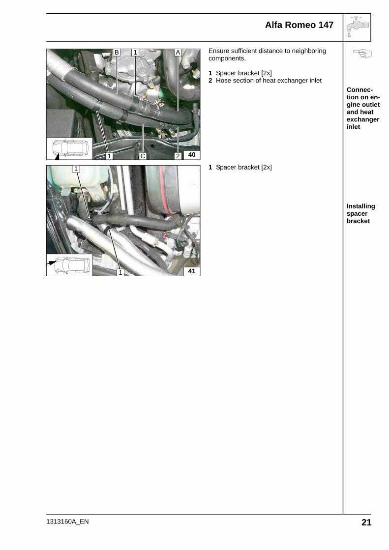
Connec-tion on en-gine outlet and heat exchanger inlet
Connec-tion on en-gine outlet and heat exchanger inlet
Installing spacer bracket
2.0 liter gasoline
Ensure sufficient distance to neighboring components.
1 Spacer bracket [3x]2 Position black (sw) rubber isolator3 Hose section of heat exchanger inlet
1.6 liter gasoline
Ensure sufficient distance to neighboring components.Route hose A under original vehicle lines.
1 Hose section of heat exchanger inlet2 Position black (sw) rubber isolator3 Spacer bracket
All gasoline vehicles
1 Spacer bracket [2x]
33
2
A
3
1 C
1B
1
342
A
3
C
B
1
35
1
1
1313160A_EN 18
Alfa Romeo 147
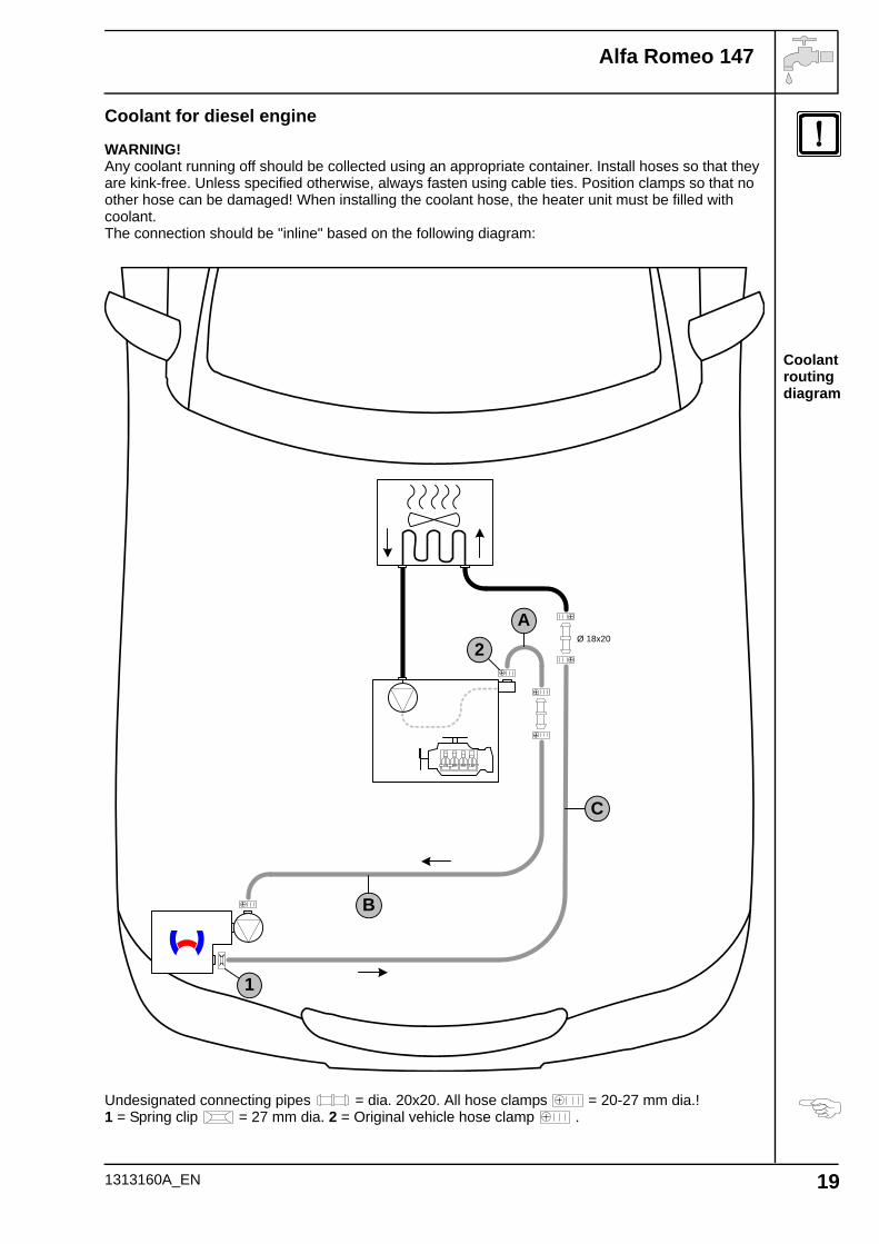
Coolant routing diagram
Coolant for diesel engine
WARNING!Any coolant running off should be collected using an appropriate container. Install hoses so that they are kink-free. Unless specified otherwise, always fasten using cable ties. Position clamps so that no other hose can be damaged! When installing the coolant hose, the heater unit must be filled with coolant.The connection should be "inline" based on the following diagram:
Undesignated connecting pipes = dia. 20x20. All hose clamps = 20-27 mm dia.!1 = Spring clip = 27 mm dia. 2 = Original vehicle hose clamp .
A
B
C
1
Ø 18x202
1313160A_EN 19
Alfa Romeo 147
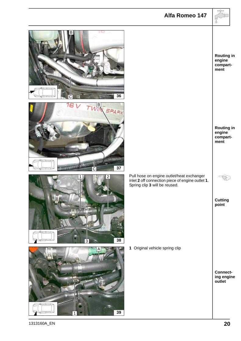
Routing in engine compart-ment
Routing in engine compart-ment
Cutting point
Connect-ing engine outlet
Pull hose on engine outlet/heat exchanger inlet 2 off connection piece of engine outlet 1. Spring clip 3 will be reused.
1 Original vehicle spring clip
36
B
C
37
B
C
38
1 2
3
39
A
1
1313160A_EN 20
Alfa Romeo 147
Connec-tion on en-gine outlet and heat exchanger inlet
Installing spacer bracket
Ensure sufficient distance to neighboring components.
1 Spacer bracket [2x]2 Hose section of heat exchanger inlet
1 Spacer bracket [2x]
40
A
C
B 1
1 2
41
1
1
1313160A_EN 21
Alfa Romeo 147
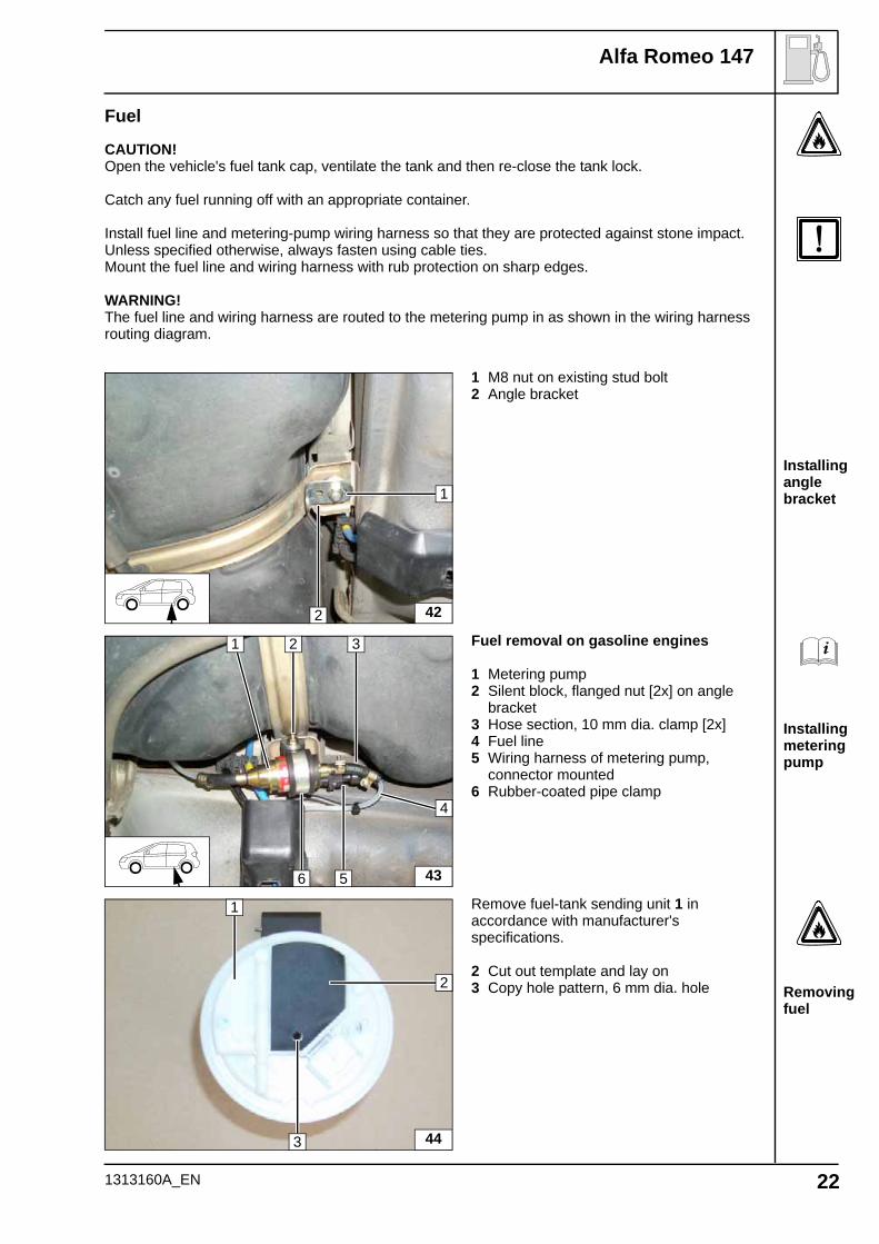
Installing angle bracket
Installing metering pump
Removing fuel
Fuel
CAUTION!Open the vehicle's fuel tank cap, ventilate the tank and then re-close the tank lock.
Catch any fuel running off with an appropriate container.
Install fuel line and metering-pump wiring harness so that they are protected against stone impact. Unless specified otherwise, always fasten using cable ties.Mount the fuel line and wiring harness with rub protection on sharp edges.
WARNING!The fuel line and wiring harness are routed to the metering pump in as shown in the wiring harness routing diagram.
1 M8 nut on existing stud bolt2 Angle bracket
Fuel removal on gasoline engines
1 Metering pump2 Silent block, flanged nut [2x] on angle
bracket3 Hose section, 10 mm dia. clamp [2x]4 Fuel line5 Wiring harness of metering pump,
connector mounted6 Rubber-coated pipe clamp
Remove fuel-tank sending unit 1 in accordance with manufacturer's specifications.
2 Cut out template and lay on3 Copy hole pattern, 6 mm dia. hole
42
1
2
43
1 2
6
3
4
5
44
1
3
2
1313160A_EN 22
Alfa Romeo 147
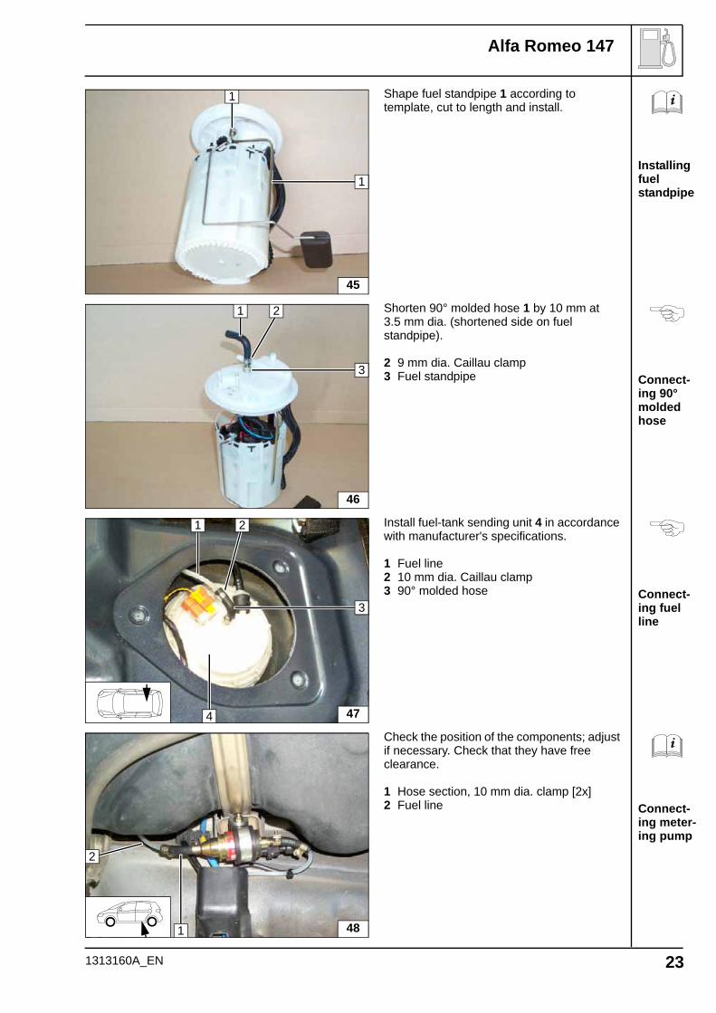
Installing fuel standpipe
Connect-ing 90° molded hose
Connect-ing fuel line
Connect-ing meter-ing pump
Shape fuel standpipe 1 according to template, cut to length and install.
Shorten 90° molded hose 1 by 10 mm at 3.5 mm dia. (shortened side on fuel standpipe).
2 9 mm dia. Caillau clamp3 Fuel standpipe
Install fuel-tank sending unit 4 in accordance with manufacturer's specifications.
1 Fuel line2 10 mm dia. Caillau clamp3 90° molded hose
Check the position of the components; adjust if necessary. Check that they have free clearance.
1 Hose section, 10 mm dia. clamp [2x]2 Fuel line
45
1
1
46
3
1 2
47
3
1 2
4
481
2
1313160A_EN 23
Alfa Romeo 147
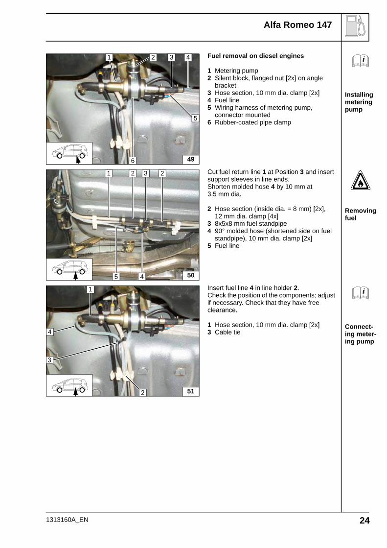
Installing metering pump
Removing fuel
Connect-ing meter-ing pump
Fuel removal on diesel engines
1 Metering pump2 Silent block, flanged nut [2x] on angle
bracket3 Hose section, 10 mm dia. clamp [2x]4 Fuel line5 Wiring harness of metering pump,
connector mounted6 Rubber-coated pipe clamp
Cut fuel return line 1 at Position 3 and insert support sleeves in line ends.Shorten molded hose 4 by 10 mm at 3.5 mm dia.
2 Hose section (inside dia. = 8 mm) [2x], 12 mm dia. clamp [4x]
3 8x5x8 mm fuel standpipe4 90° molded hose (shortened side on fuel
standpipe), 10 mm dia. clamp [2x]5 Fuel line
Insert fuel line 4 in line holder 2.Check the position of the components; adjust if necessary. Check that they have free clearance.
1 Hose section, 10 mm dia. clamp [2x]3 Cable tie
49
1 2
6
3
5
4
50
2 3 21
5 4
51
1
2
4
3
1313160A_EN 24
Alfa Romeo 147
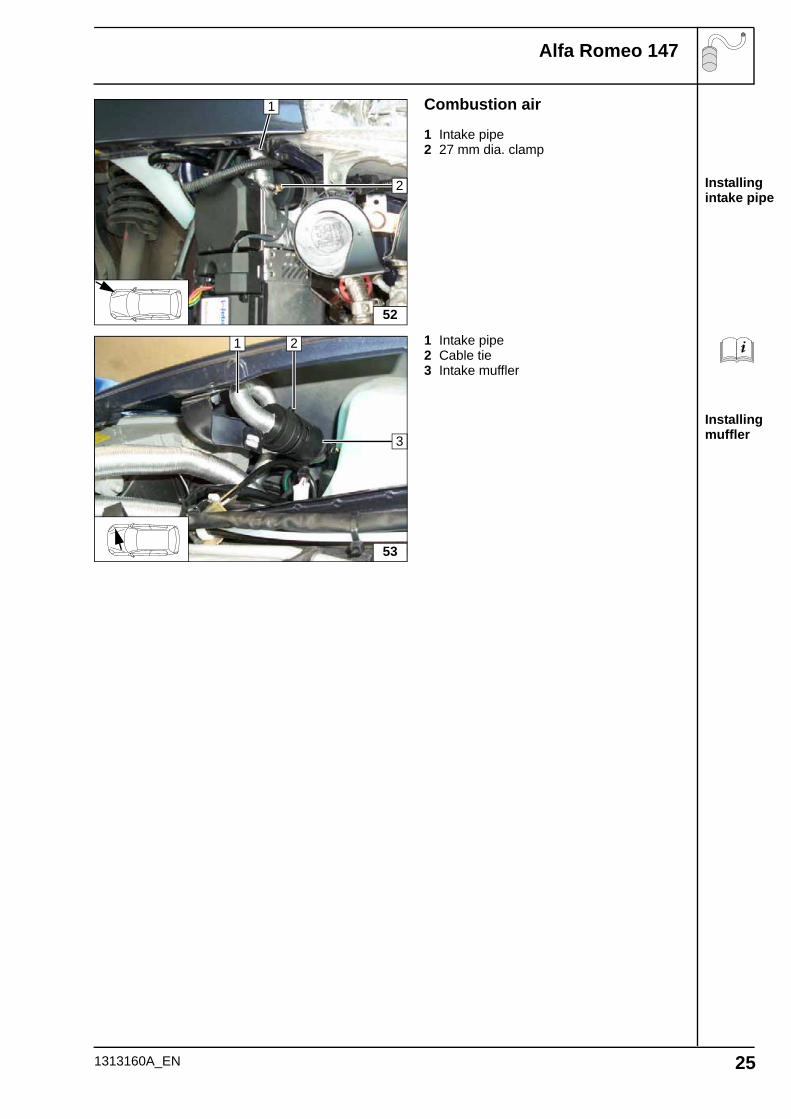
Installing intake pipe
Installing muffler
Combustion air
1 Intake pipe2 27 mm dia. clamp
1 Intake pipe2 Cable tie3 Intake muffler
52
2
1
53
3
1 2
1313160A_EN 25
Alfa Romeo 147
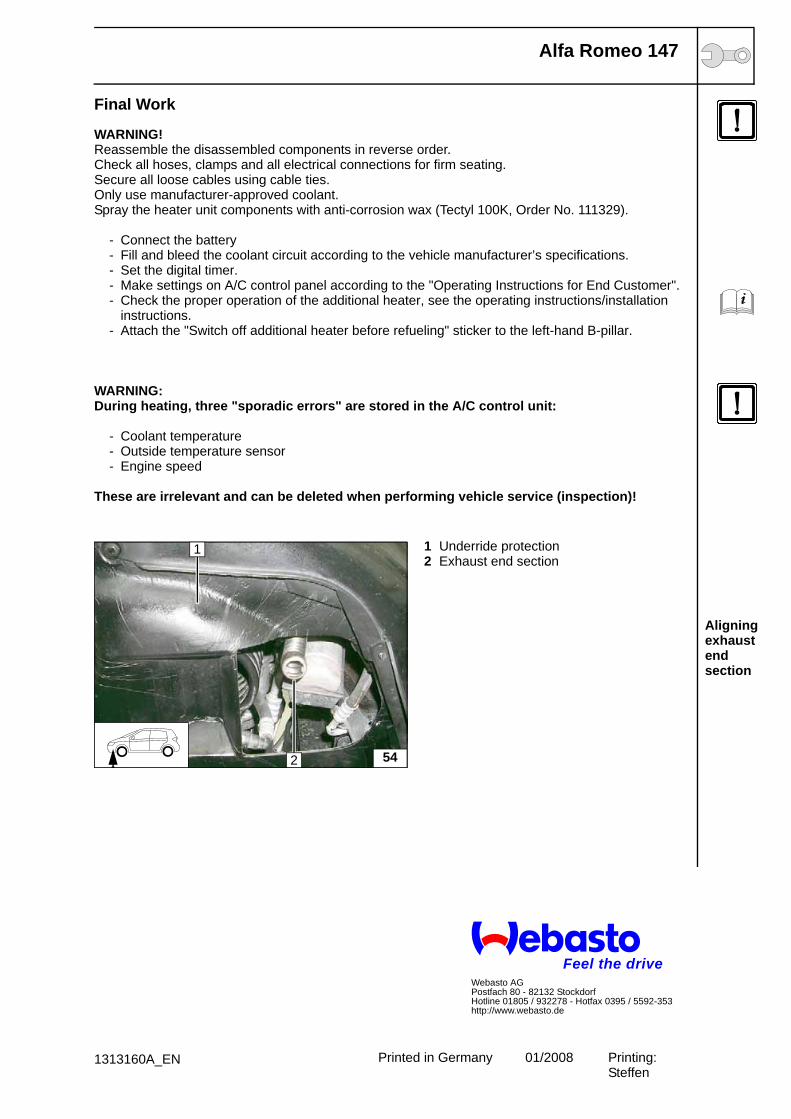
Aligning exhaust end section
Final Work
WARNING!Reassemble the disassembled components in reverse order.Check all hoses, clamps and all electrical connections for firm seating.Secure all loose cables using cable ties.Only use manufacturer-approved coolant.Spray the heater unit components with anti-corrosion wax (Tectyl 100K, Order No. 111329).
- Connect the battery- Fill and bleed the coolant circuit according to the vehicle manufacturer’s specifications.- Set the digital timer.- Make settings on A/C control panel according to the "Operating Instructions for End Customer".- Check the proper operation of the additional heater, see the operating instructions/installation
instructions.- Attach the "Switch off additional heater before refueling" sticker to the left-hand B-pillar.
WARNING:During heating, three "sporadic errors" are stored in the A/C control unit:
- Coolant temperature- Outside temperature sensor- Engine speed
These are irrelevant and can be deleted when performing vehicle service (inspection)!
1 Underride protection2 Exhaust end section
54
1
2
Feel the driveWebasto AGPostfach 80 - 82132 StockdorfHotline 01805 / 932278 - Hotfax 0395 / 5592-353http://www.webasto.de
Printed in Germany 01/2008 Printing: Steffen
1313160A_EN
Alfa Romeo 147
Manual air condition-ing
Automatic air-condi-tioning
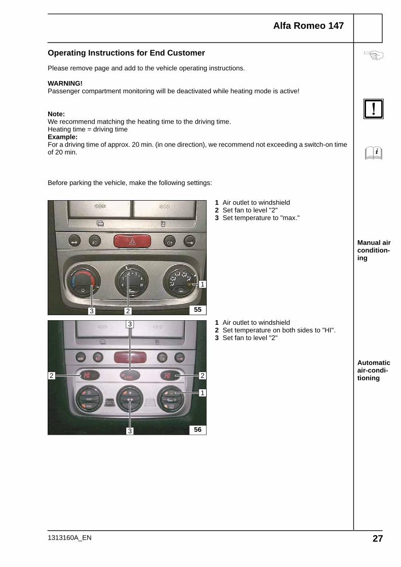
Operating Instructions for End Customer
Please remove page and add to the vehicle operating instructions.
WARNING!Passenger compartment monitoring will be deactivated while heating mode is active!
Note:We recommend matching the heating time to the driving time.Heating time = driving timeExample:For a driving time of approx. 20 min. (in one direction), we recommend not exceeding a switch-on time of 20 min.
Before parking the vehicle, make the following settings:
1 Air outlet to windshield2 Set fan to level "2"3 Set temperature to "max."
1 Air outlet to windshield2 Set temperature on both sides to "HI".3 Set fan to level "2"
553
1
2
56
2
1
2
3
3
1313160A_EN 27
Alfa Romeo 147
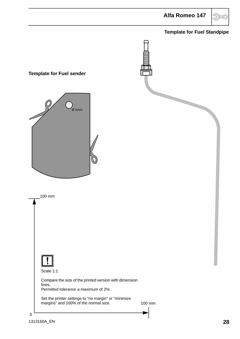
Template for Fuel Standpipe
Template for Fuel sender
1313160A_EN 280
100 mm
100 mm
Ø 6mm
Scale 1:1
Compare the size of the printed version with dimension lines.Permitted tolerance a maximum of 2%.
Set the printer settings to “no margin” or “minimize margins” and 100% of the normal size.