Installation Instructions - 3M System Overview The One Pass Fiber Pathway is found in FTTP or...
36
3M ™ One Pass Fiber Pathway Installation Instructions March 2017 78-8140-6222-6-E
Transcript of Installation Instructions - 3M System Overview The One Pass Fiber Pathway is found in FTTP or...
3M™ One Pass Fiber PathwayInstallation Instructions
March 201778-8140-6222-6-E

2 78-8140-6222-6-EMarch 2017
Contents1.0 System Overview .................................................................................................................................................................3
2.0 One Pass Fiber Pathway Components and Accessories ...............................................................................................3
3.0 Site/Floor Inspection.......................................................... .................................................................................................4
4.0 Installation Surface Preparation. .......................................................................................................................................5
5.0 Load the Utility Cart........................................................ .....................................................................................................5
6.0 Determine Duct Offset ........................................................................................................................................................6
7.0 3M™ One Pass Interior Corner Support Installation ........................................................................................................6
8.0 3M™ One Pass Exterior Corner Support Installation .......................................................................................................7
9.0 3M™ One Pass Planar Corner Installation .........................................................................................................................8
10.0 Free Form Corner Preparation ...........................................................................................................................................9
11.0 Bridge Installation ............................................................................................................................................................... 10
12.0 Fiber Distribution Terminal (FDT) Installation ................................................................................................................. 11
13.0 MPO Terminated Duct Installation .................................................................................................................................. 13
14.0 Installation Between Floors .............................................................................................................................................. 14
15.0 Funnel Installation .............................................................................................................................................................. 15
16.0 3M™ One Pass Surface Mount Multipurpose Box Installation (Wall Penetration) ................................................... 17
17.0 Liner Sheet Installation and Removal .............................................................................................................................. 19
18.0 Terminate Connectorized End of Duct in Fiber Distribution Terminal (FDT) ........................................................... 19
19.0 Duct Placement on Wall ................................................................................................................................................... 20
20.0 Interior Corner Duct Installation. ..................................................................................................................................... 21
21.0 Exterior Corner Duct Installation .................................................................................................................................... 22
22.0 Installing Corner Anchor Strip ......................................................................................................................................... 23
23.0 Inside Planar Corner Installation ..................................................................................................................................... 24
24.0 Outside Planar Corner Duct Installation ........................................................................................................................ 25
25.0 Free Form Corner Duct Installation ................................................................................................................................ 25
26.0 3M™ One Pass “T” Cover Installation ............................................................................................................................. 26
27.0 End of Run. ...........................................................................................................................................................................27
28.0 Sealing End of Duct ........................................................................................................................................................... 28
29.0 Window Cut Placement ................................................................................................................................................... 29
30.0 Point-of-Entry Box Installation ........................................................................................................................................ 30
31.0 3M™ One Pass Small Point-of-Entry Box Installation. ................................................................................................... 31
32.0 Service Connection with 3M™ One Pass Small Point-of-Entry Box .......................................................................... 32
33.0 Service Connection with Standard 3M™ One Pass Point-of-Entry Box .................................................................... 33
34.0 Fusion Splicing with the 3M™ One Pass Surface-Mount Multipurpose Box ............................................................ 33
35.0 Fiber Maintenance ............................................................................................................................................................ 35
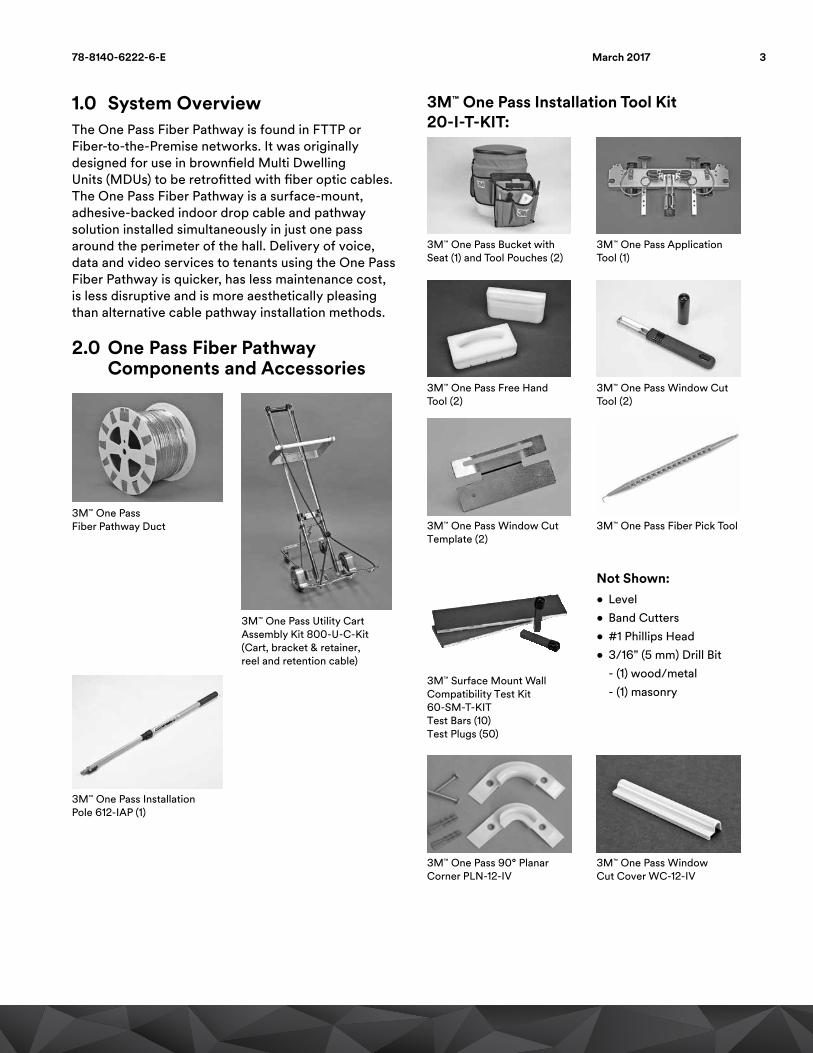
1.0 System Overview The One Pass Fiber Pathway is found in FTTP orFiber-to-the-Premise networks. It was originallydesigned for use in brownfield Multi DwellingUnits (MDUs) to be retrofitted with fiber optic cables.The One Pass Fiber Pathway is a surface-mount,adhesive-backed indoor drop cable and pathwaysolution installed simultaneously in just one passaround the perimeter of the hall. Delivery of voice,data and video services to tenants using the One PassFiber Pathway is quicker, has less maintenance cost,is less disruptive and is more aesthetically pleasingthan alternative cable pathway installation methods.
2.0 One Pass Fiber Pathway Components and Accessories
3M™ One PassFiber Pathway Duct
3M™ One Pass Utility CartAssembly Kit 800-U-C-Kit(Cart, bracket & retainer,reel and retention cable)
3M™ One Pass Installation Pole 612-IAP (1)
3M™ One Pass Installation Tool Kit 20-I-T-KIT:
3M™ One Pass Bucket with Seat (1) and Tool Pouches (2)
3M™ One Pass Application Tool (1)
3M™ One Pass Free Hand Tool (2)
3M™ One Pass Window Cut Tool (2)
3M™ One Pass Window Cut Template (2)
3M™ One Pass Fiber Pick Tool
3M™ Surface Mount WallCompatibility Test Kit60-SM-T-KITTest Bars (10)Test Plugs (50)
Not Shown:• Level• Band Cutters• #1 Phillips Head• 3/16" (5 mm) Drill Bit - (1) wood/metal - (1) masonry
3M™ One Pass 90° PlanarCorner PLN-12-IV
3M™ One Pass WindowCut Cover WC-12-IV
378-8140-6222-6-E March 2017

3M™ One Pass Thru WallFunnel TWF-12-IV
3M™ One Pass Bridge, Anchor Plate Kit BRIDGE-100-4
3M™ One Pass Hardware Kit78-H-KIT
3M™ Scotchbrite Microfiber Hardwood Floor Mop (or equivalent)
3M™ One Pass Small Surface-Mount Point-of-Entry Box SM-SMALL POE-10-IV
3M™ One Pass Surface-Mount Multipurpose Box SM-MP-10-IV
3M™ One Pass T-Cover T-12-IV
3M™ One Pass Surface-Mount Point-of-Entry Box SM-POE-10-IV
3M™ One Pass Interior Corner INT-17-IV
3M™ One Pass Exterior Corner EXT-12-IV
Not Shown:• Common Wax Paper (for liner sheets)
• 3M™ Scotch Blue Painter's Tape (1")
Prior to Install3.0 Site/Floor InspectionItems Required: Paper, pen, camera3.1 A site inspection is required prior to the
installation of the 3M™ One Pass Fiber Pathway to ensure craftsmen have appropriate tools and materials onsite once installation begins.
3.2 Items to note include:
a. The number of living units per floor
b. The location of fiber distribution terminals (FDTs) within the building (i.e. on that floor, above or below installation closet, or open or closed stairwell)
c. The width of the hallways on each floor (Min. ~3 feet (91.4 cm))
d. The height of the reference surface on each floor (Max. 12 feet (3.7 m)) when using the 3M™ One Pass Application Tool
e. Ratio of height to width should be ≤ 3:1 (ex: 8-foot (2.4 m) ref. surface with 3-foot wide hallway is acceptable)
f. Reference surface type and construction. The installation tool uses a ceiling, crown molding, or the like with a solid, stable, ¼" (6 mm) minimum width to apply the duct while referencing that surface.
g. The distance around the perimeter of the hallways on each floor
h. The distance from the proposed fiber distribution unit that will be serving that floor
i. The number and type of corners found in the hallways and stairwells along the installation path of the 3M™ One Pass Fiber Pathway
j. Number of disruptions in the reference surface used to guide the installation tool
k. Disruptions in the wall surface itself
l. Open or closed stairwell or riser closet
m. Duct direction is relative to the way it will be installed in hallway once it enters the hallway (i.e. left or right)
n. Obstacles such as pipes, vents, electrical cords that must be avoided
o. Confirm wall surfaces have been tested for adhesive compatibility. If they have not been tested, install test plugs/bars (60-SM-T-KIT) where duct will be placed at inconspicuous locations in the hallway. If test plugs/bars remain adhered to the wall after 24 hours, the surface is suitable.
4 78-8140-6222-6-EMarch 2017
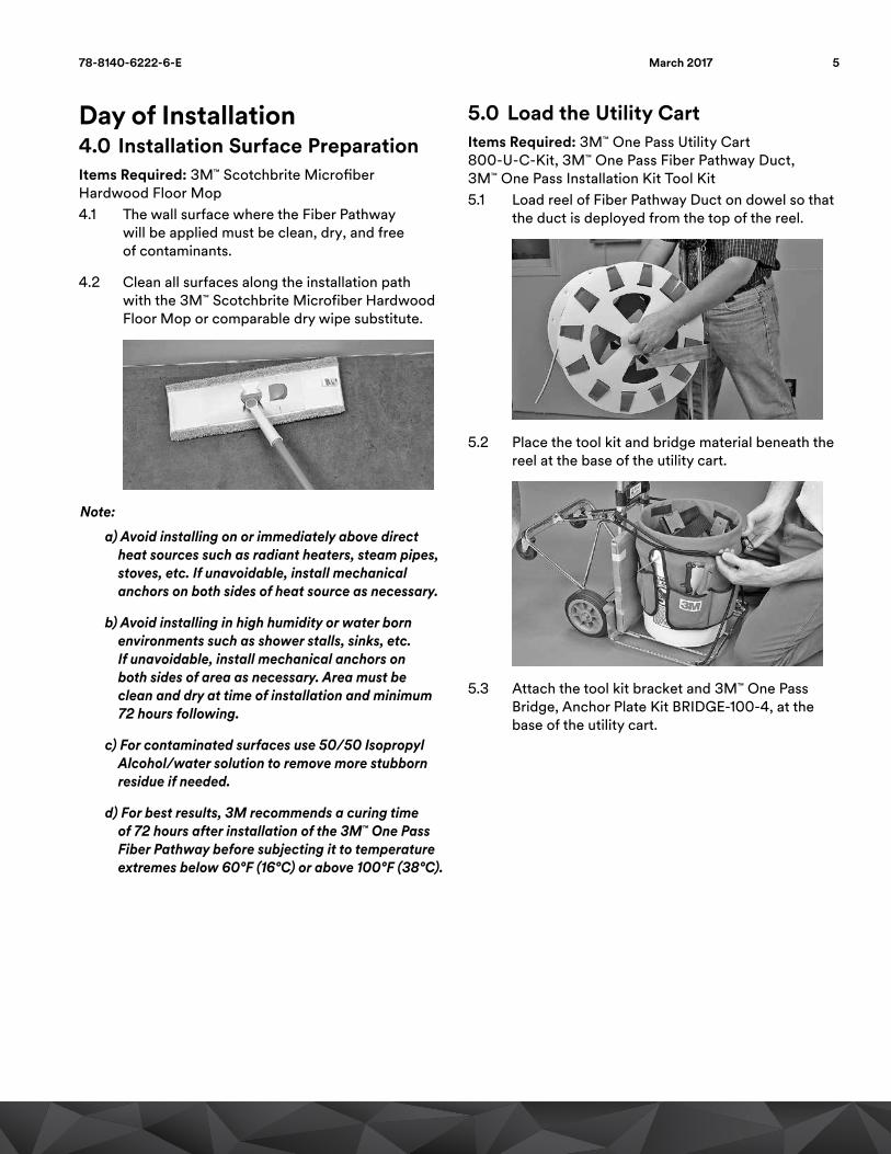
Day of Installation4.0 Installation Surface PreparationItems Required: 3M™ Scotchbrite Microfiber Hardwood Floor Mop4.1 The wall surface where the Fiber Pathway
will be applied must be clean, dry, and free of contaminants.
4.2 Clean all surfaces along the installation path with the 3M™ Scotchbrite Microfiber Hardwood Floor Mop or comparable dry wipe substitute.
Note:
a) Avoid installing on or immediately above direct heat sources such as radiant heaters, steam pipes, stoves, etc. If unavoidable, install mechanical anchors on both sides of heat source as necessary.
b) Avoid installing in high humidity or water born environments such as shower stalls, sinks, etc. If unavoidable, install mechanical anchors on both sides of area as necessary. Area must be clean and dry at time of installation and minimum 72 hours following.
c) For contaminated surfaces use 50/50 Isopropyl Alcohol/water solution to remove more stubborn residue if needed.
d) For best results, 3M recommends a curing time of 72 hours after installation of the 3M™ One Pass Fiber Pathway before subjecting it to temperature extremes below 60°F (16°C) or above 100°F (38°C).
5.0 Load the Utility CartItems Required: 3M™ One Pass Utility Cart 800-U-C-Kit, 3M™ One Pass Fiber Pathway Duct, 3M™ One Pass Installation Kit Tool Kit5.1 Load reel of Fiber Pathway Duct on dowel so that
the duct is deployed from the top of the reel.
5.2 Place the tool kit and bridge material beneath the reel at the base of the utility cart.
5.3 Attach the tool kit bracket and 3M™ One Pass Bridge, Anchor Plate Kit BRIDGE-100-4, at the base of the utility cart.
578-8140-6222-6-E March 2017

6.0 Determine Duct Offset• Duct can be placed from ¼" (6 mm) to 3½" (89 mm)
below the reference surface.
• Evaluate the installation surface and determine the correct offset distance.
• Offset distance may be determined based on various obstacles, wall surface conditions, interior living unit ceiling height, reach, etc.
• Choose an offset that will ease installation difficulty while maintaining aesthetics.
• Duct offset distances are set at ¼" (6 mm), ½" (13 mm), 1½" (38 mm), 2½" (64 mm) & 3½" (89 mm).
• The minimum recommended duct offset from the reference surface is 1/4" (6 mm).
• Grooves located on the side of the 3M™ One Pass Free Hand Tool act as guides for corner support placement for the 1/4" offset.
Note: Grooves in the free hand tool locate the bottom of the duct and corner accessories.
• When marking wall surfaces for accessory installation, the free hand tool, tape measure, or other template may be used.
7.0 3M™ One Pass Interior Corner Support Installation
7.1 Identify corner location based on duct offset from reference surface.
7.2 Mark the location for the bottom of the interior corner support using the free hand tool or equivalent. Measured distance is the preferred offset + ½" (13 mm) e.g., 1/4" offset + 1/2" = mark at 3/4".
7.3 Pinch ends of interior corner support together.
7.4 Align bottom edge of the 3M™ One Pass Interior Corner support with the marks made on the wall.
7.5 Place spine of the interior corner support snug into the interior corner, aligning the bottom edge with the marks made on the wall.
7.6 Holding the strip in place with holes flat against the wall, mark hole locations on the wall for drilling anchors.
7.7 Drill and insert screw anchors into holes, flush to wall surface.
7.8 Attach metal strip over the 3M™ Interior Corner support using #4 countersink screws.
7.9 Peel and remove protective liner from strip.
6 78-8140-6222-6-EMarch 2017
8.0 3M™ One Pass Exterior Corner Support Installation
8.1 Identify the corner location based on duct offset from reference surface.
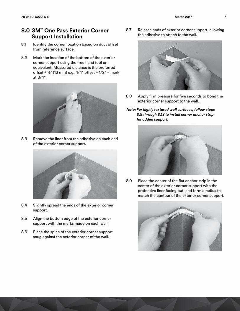
8.2 Mark the location of the bottom of the exterior corner support using the free hand tool or equivalent. Measured distance is the preferred offset + ½" (13 mm) e.g., 1/4" offset + 1/2" = mark at 3/4".
8.3 Remove the liner from the adhesive on each end of the exterior corner support.
8.4 Slightly spread the ends of the exterior corner support.
8.5 Align the bottom edge of the exterior corner support with the marks made on each wall.
8.6 Place the spine of the exterior corner support snug against the exterior corner of the wall.
8.7 Release ends of exterior corner support, allowing the adhesive to attach to the wall.
8.8 Apply firm pressure for five seconds to bond the exterior corner support to the wall.
Note: For highly textured wall surfaces, follow steps 8.9 through 8.13 to install corner anchor strip for added support.
8.9 Place the center of the flat anchor strip in the center of the exterior corner support with the protective liner facing out, and form a radius to match the contour of the exterior corner support.
778-8140-6222-6-E March 2017

8.10 Holding the strip in place with holes flat against the wall, mark hole locations on the wall for drilling anchors.
8.11 Drill and insert screw anchors into holes, flush to wall surface.
8.12 Attach metal strip over exterior corner support using #4 countersink screws.
8.13 Peel and remove protective liner from strip.
9.0 3M™ One Pass Planar Corner Installation
Determine the route and ceiling offset to be used.
9.1 Select the correct planar corner for installation based on the location of the flange of the duct.
Outside Flange
Inside Flange
9.2 Planar corners are pre-positioned prior to applying pathway duct. Mark each location with the predetermined offset. Measured distance is the offset plus 1/2 inch (12 mm) e.g., 1/4" offset + 1/2" = mark at 3/4". This mark will locate both the edge of the flange on the fiber pathway and the edge of the planar corner piece.
OffsetOffset + 1/2" =3/4" (19mm)
Inside
Outside
DuctDuct
Inside Inside
Outside Outside
8 78-8140-6222-6-EMarch 2017

9.3 Anchors or screws (depending on wall construction) should be used if the mounting surface is poor or highly textured. Use the holes in the corner for the location of the anchors. Use a 3/16" (5 mm) bit and install the anchors. Ensure the anchors are flush with the wall surface.
9.4 Remove the liner from the adhesive and install the 3M™ One Pass Planar Corner. Align with anchors or pre-drilled holes if screws are used.
9.5 Press down firmly and hold the corner piece for five seconds to set the adhesive. Install the screws if the pieces are mechanically anchored.
Note: Do not over tighten the mounting screws.
10.0 Free Form Corner Preparation Items Required: Measuring device, pen, ScotchBlue™ Painter's Tape 2090Definition: Corners where included angle is greater than 90 and less than 180 degrees and which are placed in a planar direction without support pieces.The minimum radius for a free form corner is 2-feet (61 cm). If the radius is tighter than 2 feet (61 cm), then anchoring in and out of the corner is required.
10.1 To determine the start and end location of a free form corner, measure 6" (152 mm) on either side from the center of the corner.
10.2 From the 6" (152 mm) marks, measure the offset distance.
10.3 Align a length of ScotchBlue Painter's Tape 2090 with the marks on either side of the corner.
Note: A mechanical anchor is required at the beginning and end of the free form corners if the length of the duct, including the free form corner, is greater than 10 feet (3 m) between locations where the duct is mechanically fastened.
978-8140-6222-6-E March 2017

11.0 Bridge InstallationItems Required: 3M™ One Pass Bridge, Anchor Plate Kit, Bridge-100-4, level, pen
Bridges are used to span disruptions in wall surfaces such as columns, air conditioning vents, emergency lighting and door frame moldings. They could also be used to provide additional anchoring for duct in locations where the wall surface is poor (i.e. water damage).
Bridging an obstacle:11.1 Measure the approximate height of the disruption
from the wall surface.
11.2 Multiply the height by six, this is the minimum length of the bridge to be cut.
11.3 Pull approximate amount of bridge material required from supply box.
11.4 If calculated length falls between two holes in the bridge material, add the additional length to the section to leave a pre-punched hole at each end of the bridge piece.
11.5 Cut bridge section, leaving a pre-punched hole at each end. Each bridge must be supported by at least two anchor screws. (One screw recommended on each side for fastening security)
11.6 Measure and mark the surface at the chosen offset from the reference surface.
11.7 Align bottom edge of bridge with mark.
11.8 Center bridge material over obstruction.
11.9 Form bridge by hand, maintaining a gradual slope on both sides of the obstruction.
11.10 Mark first anchor hole location by using pre-punched hole in one end of bridge as template. Be sure to maintain form of bridge section while marking hole for accuracy.
10 78-8140-6222-6-EMarch 2017
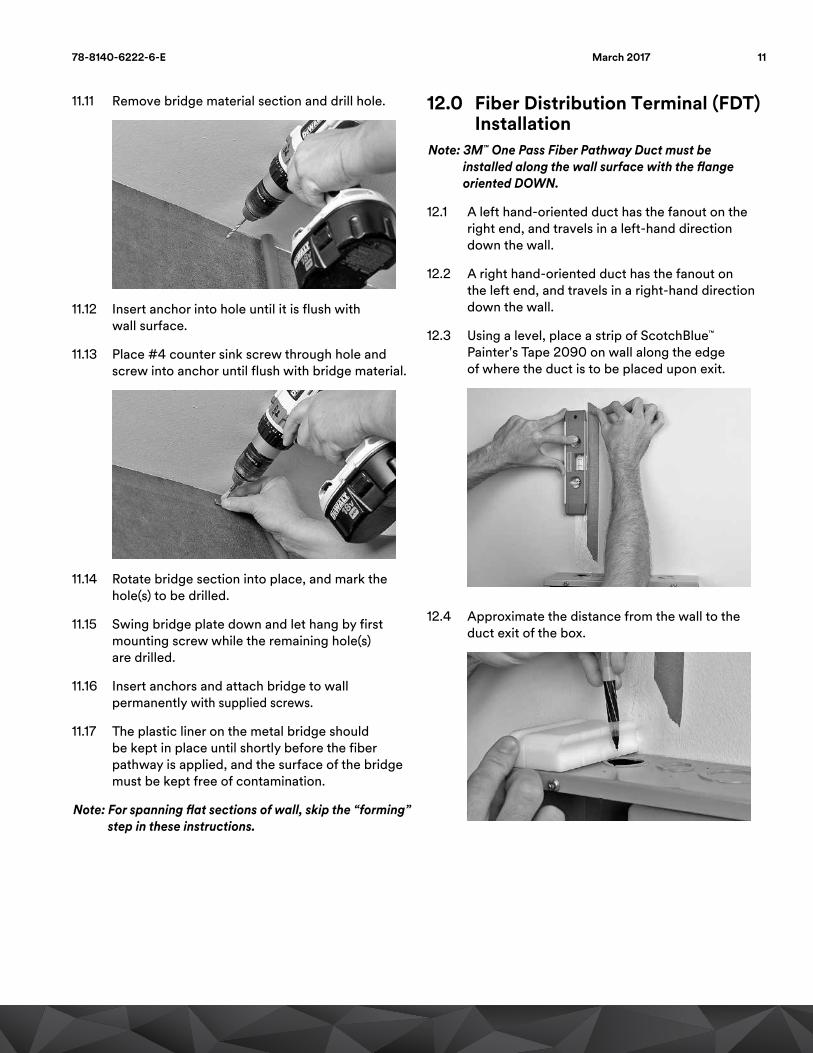
11.11 Remove bridge material section and drill hole.
11.12 Insert anchor into hole until it is flush with wall surface.
11.13 Place #4 counter sink screw through hole and screw into anchor until flush with bridge material.
11.14 Rotate bridge section into place, and mark the hole(s) to be drilled.
11.15 Swing bridge plate down and let hang by first mounting screw while the remaining hole(s) are drilled.
11.16 Insert anchors and attach bridge to wall permanently with supplied screws.
11.17 The plastic liner on the metal bridge should be kept in place until shortly before the fiber pathway is applied, and the surface of the bridge must be kept free of contamination.
Note: For spanning flat sections of wall, skip the “forming” step in these instructions.
12.0 Fiber Distribution Terminal (FDT) Installation
Note: 3M™ One Pass Fiber Pathway Duct must be installed along the wall surface with the flange oriented DOWN.
12.1 A left hand-oriented duct has the fanout on the right end, and travels in a left-hand direction down the wall.
12.2 A right hand-oriented duct has the fanout on the left end, and travels in a right-hand direction down the wall.
12.3 Using a level, place a strip of ScotchBlue™ Painter's Tape 2090 on wall along the edge of where the duct is to be placed upon exit.
12.4 Approximate the distance from the wall to the duct exit of the box.
1178-8140-6222-6-E March 2017

12.5 Multiply this distance by three. Measure away from the edge of the box the calculated distance and place a mark on the ScotchBlue Painter's Tape 2090.
12.6 Drill an anchor hole 1/4" (6 mm) from the edge of the ScotchBlue Painter's Tape 2090 (in the installation path of the duct) and insert anchor.
12.7 Form the bridge to pass through center of hole upon final bridge installation.
12.8 Remove protective film from bridge strip and install the grommet.
12.9 Attach the bridge, top…
12.10 …and bottom.
12.11 Feed cables through grommet into box.
12 78-8140-6222-6-EMarch 2017

12.12 Secure duct to bridge using cable ties.
12.13 Remove liner at duct exit point from fiber distribution terminal.
12.14 Adhere duct to bridge.
12.15 Install grommet in position at the cable exit point.
13.0 MPO Terminated Duct Installation
13.1 The MPO-terminated duct and pull-eye may be pulled through conduit with a minimum inside diameter of one inch. The maximum pulling force must be 20 lb. or less, utilizing the molded pull-eye that is assembled over the MPO connector. Typically, the pulling force should be less than 10 lb.
Using thumbs, pry open at rear with equal force
13.2 To expose the MPO connector, the pull-eye should be removed by prying the two halves apart, as shown in the photo above.
Notes:
• Only the riser rated jacketed cable and MPO connector may be installed in a riser space.
• For optimal duct support and flammability performance, the white duct portion should always be attached to the wall or supported with metal bridge material Section 14.0 “Installation Between Floors.”
• The MPO connector should be cleaned per your company’s standard cleaning practice, before insertion into a standard MPO adapter using an IBCTM MPO Cleaning Tool (by US Conec), a CLETOP MPO Cleaner, or equivalent.
1378-8140-6222-6-E March 2017

14.0 Installation Between Floors14.1 When the duct makes a transition (vertically) from
one floor to another it must be supported. The bridge material is used to add support to the duct.
14.2 Use the bridge to determine the length required.
14.3 Run the bridge (this is just the bridge, do not stick the duct to it at this point) from the upper floor to the lower floor.
14.4 Mark the bridge for cutting. Increase the length required to include a hole at each end. These holes will be used for mounting near each end within the FDT box and the transition point to horizontal cabling.
14.5 Tie a pull in line to the bridge before you retrieve it. This will place the pull line for you.
14.6 Pull the bridge back to the origination point and cut to length.
14.7 Determine the amount of slack required from the end of the fanout to store slack duct in the box (at least 3 – 4 feet (91.4 cm – 121.9 cm) are recommended). Mark this location. This is where you will begin to stick your duct to the bridge. Cut the red liner.
14.8 Remove the red liner in a direction away from the fanout. This will be the point that you start sticking the duct to the bridge. Remove the white liner from the bridge. This is the surface that will attach to the duct. Stick the duct to the bridge — do not cover the first or last hole of the bridge with duct. We will use these holes to anchor the duct at each floor.
14.9 Use a cable tie to reinforce the duct to the bridge.
14.10 Tape the unstuck end of the bridge to the duct to keep it from snagging as you pull it vertically between floors.
14 78-8140-6222-6-EMarch 2017

14.11 Pull the duct through the vertical pathway and adhere the bridge as you pull. Make sure not to cover the first and last holes on the bridge with duct.
14.12 Remove the tape. Fasten the bridge to the back wall inside the FDT box and at floor level of the horizontal cable.
14.13 Install the duct per practice.
Note: When transitioning through the riser, the 3M™ One Pass Fiber Pathway with bridge attached must be contained within a riser rated conduit as required by local ordinances or company practice. This is a requirement in the US to pass UL 1666 Riser Flammability Testing.
15.0 Funnel InstallationThe funnel is used to cover the holes that are drilled through firewalls. The funnel consists of four pieces, the main body, a small insert, screw and an anchor.At no time should the fiber pathway be routed through a wall without being inside a metal conduit.
15.1 Determine and mark hole location for passing duct through wall.
15.2 Drill 1" (25 mm) diameter hole at marked location.
15.3 Determine direction of travel of duct down the hallway. Check to make sure duct will be placed in the “flange down” position during installation.
15.4 Place funnel into hole to ensure fit, and locate the anchor hole of the funnel on the opposite side of the hole as the direction of travel of the duct.
15.5 Mark location of center of anchor hole on the wall using the funnel as template.
15.6 Remove the funnel from the wall and drill a 3/16" (5 mm) hole for the funnel anchor.
1578-8140-6222-6-E March 2017
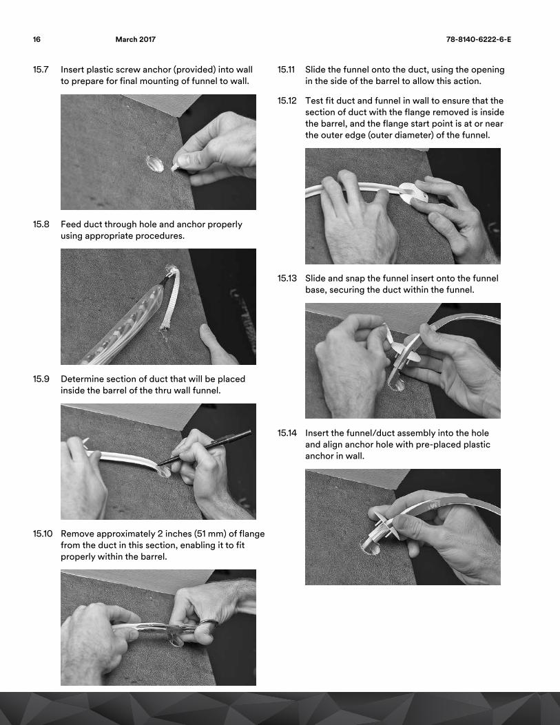
15.7 Insert plastic screw anchor (provided) into wall to prepare for final mounting of funnel to wall.
15.8 Feed duct through hole and anchor properly using appropriate procedures.
15.9 Determine section of duct that will be placed inside the barrel of the thru wall funnel.
15.10 Remove approximately 2 inches (51 mm) of flange from the duct in this section, enabling it to fit properly within the barrel.
15.11 Slide the funnel onto the duct, using the opening in the side of the barrel to allow this action.
15.12 Test fit duct and funnel in wall to ensure that the section of duct with the flange removed is inside the barrel, and the flange start point is at or near the outer edge (outer diameter) of the funnel.
15.13 Slide and snap the funnel insert onto the funnel base, securing the duct within the funnel.
15.14 Insert the funnel/duct assembly into the hole and align anchor hole with pre-placed plastic anchor in wall.
16 78-8140-6222-6-EMarch 2017
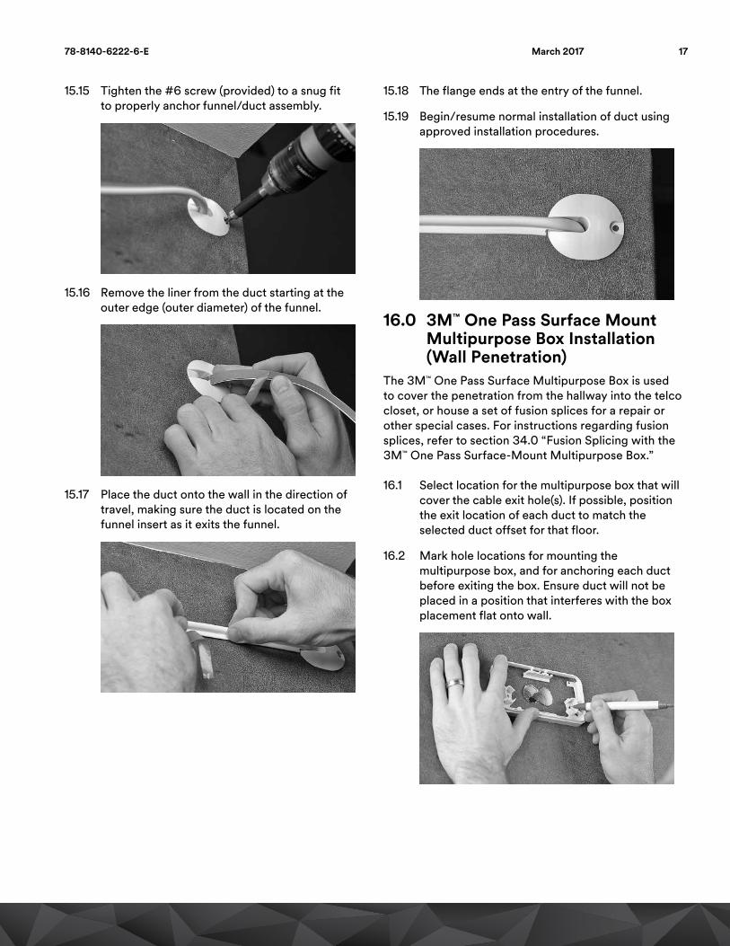
15.15 Tighten the #6 screw (provided) to a snug fit to properly anchor funnel/duct assembly.
15.16 Remove the liner from the duct starting at the outer edge (outer diameter) of the funnel.
15.17 Place the duct onto the wall in the direction of travel, making sure the duct is located on the funnel insert as it exits the funnel.
15.18 The flange ends at the entry of the funnel.
15.19 Begin/resume normal installation of duct using approved installation procedures.
16.0 3M™ One Pass Surface Mount Multipurpose Box Installation (Wall Penetration)
The 3M™ One Pass Surface Multipurpose Box is used to cover the penetration from the hallway into the telco closet, or house a set of fusion splices for a repair or other special cases. For instructions regarding fusion splices, refer to section 34.0 “Fusion Splicing with the 3M™ One Pass Surface-Mount Multipurpose Box.”
16.1 Select location for the multipurpose box that will cover the cable exit hole(s). If possible, position the exit location of each duct to match the selected duct offset for that floor.
16.2 Mark hole locations for mounting the multipurpose box, and for anchoring each duct before exiting the box. Ensure duct will not be placed in a position that interferes with the box placement flat onto wall.
1778-8140-6222-6-E March 2017

16.3 Drill holes and insert plastic screw anchors into marked locations. Drill additional anchoring locations through box if necessary to create adequate anchoring to wall.
16.4 Insert and pull the duct fanout pulleye(s) into the fiber distribution terminal, and anchor fanout(s) using standard practice.
16.5 Place ScotchBlue™ Painter’s Tape 2090 onto wall surface beginning at exit point of box to create a reference edge at the desired offset from reference surface.
16.6 Mark locations of duct anchors to locate screw location after duct is installed over the anchors.
16.7 Begin peeling liner from duct at wall exit and apply, taking care to place duct so that the flange will pass over the anchor location, as well as exit the side of the box with minimal bending stress.
16.8 Use painter's tape reference edge and free hand tool to ensure straightness, and follow standard installation practice for duct.
16.9 Insert #4 countersink screw through flange into anchor within box to secure.
16.10 Place multipurpose box over pass-through location and duct(s), and insert anchoring screws for box. Base of multipurpose box should sit flat on wall after installation.
18 78-8140-6222-6-EMarch 2017

17.0 Liner Sheet Installation and RemovalItems Required: Common wax paper to be used as liner sheets, measuring device, ScotchBlue™ Painter’s Tape 2090
Note: Liner sheets prevent the duct from bonding permanently to the wall surface so it can later be repositioned by hand ensuring a straight installation. For use where known inconsistencies or disruptions in the reference surface (ceiling) are present.
17.1 Place edge of liner sheet ½" (13 mm) prior to disruption in reference surface, snug up against reference surface/ceiling.
17.2 Apply a strip of ScotchBlue Painter's Tape 2090, slightly longer than the length of the liner sheet, just below installation height of duct.
17.3 Leave in place during installation.
17.4 After duct installation, the liner sheet is removed by gently pulling it out from under the duct.
17.5 The duct is then placed in a straight line by hand or with the free hand tool depending on the offset.
17.6 Apply pressure and smooth duct in place.
18.0 Terminate Connectorized End of Duct in Fiber Distribution Terminal (FDT)Items Required: Reel of 3M™ One Pass Fiber Pathway Duct
18.1 One end of the reel of 3M™ One Pass Fiber Pathway Duct can be pre-connectorized at a 3M factory with SC connectors (optional). This end is plugged into a fiber distribution terminal.
18.2 Use company approved method for anchoring duct and routing pigtails.
1978-8140-6222-6-E March 2017

19.0 Duct Placement on WallItems Required: 3M™ One Pass Installation Tool Kit (20-I-T-Kit), 3M™ One Pass Installation Pole, ladder, 3M™ One Pass One Pass Fiber Pathway Duct and 3M™ One Pass Utility Cart Assembly Kit (800-U-C-Kit)
Note: A two-person crew is recommended.
19.1 The adhesive selected for the One Pass Fiber Pathway is a permanent adhesive. 3M does not recommend moving or repositioning the duct once installed. If, for some reason the duct does need to be moved, a mechanical fastener is required to secure the duct to wall. Use the 3M™ One Pass Free Hand Tool Template or measure down from reference surface. Mark the wall at the pre-determined offset distance in two places at least 6" (152 mm) apart. A leveling device can be used to ensure duct is placed straight.
19.2 Place top edge of the tape along the marks.
Note: Recommended air and duct temperature for install is 60°F–100°F (16°C–38°C).
19.3 Apply the first 18" (457 mm) of duct (flange down) on the wall using the Free Hand Tool along top edge of tape placed temporarily on the wall as a guide.
19.4 Drop the duct into the tool lead in ramp (A), positioning the liner removal post (B) behind the duct. Slide the tool into position with the grooves of the installation wheels over barrel of the duct (C).
A
C
B
Note: For textured reference surfaces, use the installation tool texture wheels (shown below) as described in the MDU Installation Tool Instruction Manual. Compress texture wheels to match duct offset when placing install tool onto duct and beginning run.
20 78-8140-6222-6-EMarch 2017

19.5 Wrap liner around liner (A) removal post (B) and through the corner notch (C) on the front of the tool.
C
A
B
19.6 Tape liner to wall just below height of lower rear wheel using painter’s tape.
19.7 Insert pole into tool.
19.8 Activate the tool by pressing the spring loaded arm into the wall.
19.9 Begin to move tool across the wall, maintaining mostly inward and some upward pressure on the wall.
Note: Spring mechanism of tool must be activated (completely compressed) to ensure proper application force of duct.
19.10 When reaching end of run, stop tool motion, and hold the tool stationary.
19.11 Remove pole first, then lift installation tool wheels from duct.
20.0 Interior Corner Duct InstallationItems Required: 3M™ One Pass Corner Support Covers, measuring device, ScotchBlue™ Painter’s Tape 2090
20.1 Stop tool 6" (152 mm) before corner support piece (previously installed).
20.2 Unsnap extension pole from tool.
20.3 Lift installation tool wheels from duct and slide tool away from duct.
2178-8140-6222-6-E March 2017

20.4 Remove enough liner from duct to transition beyond corner support piece.
20.5 Place duct in support piece maintaining constant contact with the support piece, pushing duct into the bend and around the corner.
20.6 Apply pressure and smooth duct into place by hand or using 3M™ One Pass Free Hand Tool at proper offset location.
20.7 Place corner cover on top. Cover should snap in place when secure.
20.8 Refer to Section 19.0 to exit corner and begin application down adjacent wall.
21.0 Exterior Corner Duct Installation21.1 Identify the corner location based on duct offset
from reference surface.
21.2 Mark the location of the bottom of the exterior corner support using the free hand tool or equivalent. Measured distance is the preferred offset + ½".
21.3 Remove the liner from the adhesive on each end of the exterior corner support.
21.4 Slightly spread the ends of the exterior corner support.
21.5 Align the bottom edge of the exterior corner support with the marks made on each wall.
21.6 Place the spine of the exterior corner support snug against the exterior corner of the wall.
22 78-8140-6222-6-EMarch 2017

21.7 Release ends of exterior corner support, allowing the adhesive to attach to the wall.
21.8 Apply firm pressure to bond the exterior corner support to the wall.
22.0 Installing Corner Anchor StripNote: For heavily textured wall surfaces, follow steps
8.9 through 8.13 to install corner anchor strip for added support.
22.1 Place the center of the flat anchor strip in the center of the exterior corner support with the protective liner facing out, and form a radius to match the contour of the exterior corner support.
22.2 Holding the strip in place with holes flat against the wall, mark hole locations on the wall for drilling anchors.
22.3 Drill and insert screw anchors into holes, flush to wall surface.
22.4 Attach metal strip over exterior corner support using #4 countersink screws.
22.5 Peel and remove protective liner from strip.
2378-8140-6222-6-E March 2017

23.0 Inside Planar Corner Installation23.1 Apply the 3M™ One Pass Fiber Pathway Duct to
the wall stopping 8–10 inches (203–254 mm) from the corner.
23.2 With liner still intact, bring duct up to the corner and use a pen to mark where the flange lines up with the outside edge of the planar corner as shown.
23.3 Remove 1 to 1-1/4 inches (25–32 mm) of the flange starting at the mark.
Note: A set of end nipper pliers such as a CHANNELLOCK® No. 356, Home Depot Husky 831-596 or equivalent with a 1" (25 mm) wide-cutting jaw is recommended to remove flange. Do not cut into the fiber section. A pair of snips can also be used.
23.4 Remove enough of the liner to route the Fiber Pathway Duct into and out of the Planar Corner. Start by aligning the edge of the duct with the inside edge on the corner piece. With a slight rolling motion, tuck the duct flange under the hold down as shown. Align exiting duct edge with the edge of the corner piece.
Note: Do not stretch the duct through the corner.
23.5 Firmly press and hold the duct into place onto the corner piece and the wall for five seconds.
24 78-8140-6222-6-EMarch 2017

24.0 Outside Planar Corner Installation
24.1 Remove enough of the liner to route the duct into and out of the planar corner. Align the flange edge of the duct with the edge on the corner piece.
Note: A flange relief cut is not required for an outside flange corner.
24.2 Continued routing the duct under the hold down. A slight twist while routing the duct around the corner will force the flange to lay flat. Align exiting duct edge with the edge of the corner piece.
Note: Do not stretch the duct through the corner.
24.3 Firmly press and hold the duct into place onto the corner piece and the wall for five seconds.
25.0 Free Form Corner Duct Installation
Tools Required: 3M™ One Pass Free Hand Tool, measuring device, ScotchBlue™ Painter’s Tape 2090, pen, sheath knife
25.1 Stop duct application with tool 6–12" (152 mm – 305 mm) before corner transition.
Note: We require mechanical anchors at the beginning and end of the free form corners if the length of the duct, including the free form corner, is greater than 10 feet (3 m) between locations where the duct is mechanically fastened.
25.2 Remove liner and place duct by hand around corner. The curve of the corner should begin and end 6" (152 mm) from its center, ensuring a uniform bend.
25.3 Align edge of duct after corner with ScotchBlue Painter’s Tape 2090 and resume application with tool. After exiting the corner, the bottom of the duct is aligned with the top edge of the painter’s tape. Installation of the duct with the application tool can be resumed.
2578-8140-6222-6-E March 2017
26.0 3M™ One Pass “T” Cover Installation
The 3M™ One Pass T Cover allows the installer to redirect a fiber from the main duct. One application would be to accommodate a lower ceiling height in a living unit.
The T cover requires a piece of empty duct. Cut the desired length of duct from an extra spool, and remove the fiber from this duct.
If a 3M™ One Pass Point-of-Entry Box is located in the location where the T cover is to be installed, remove the current box, and uncoil the stored fiber.
Note: Do not remove the adhesive liners from the T cover at this step. The T cover is used as a template first.
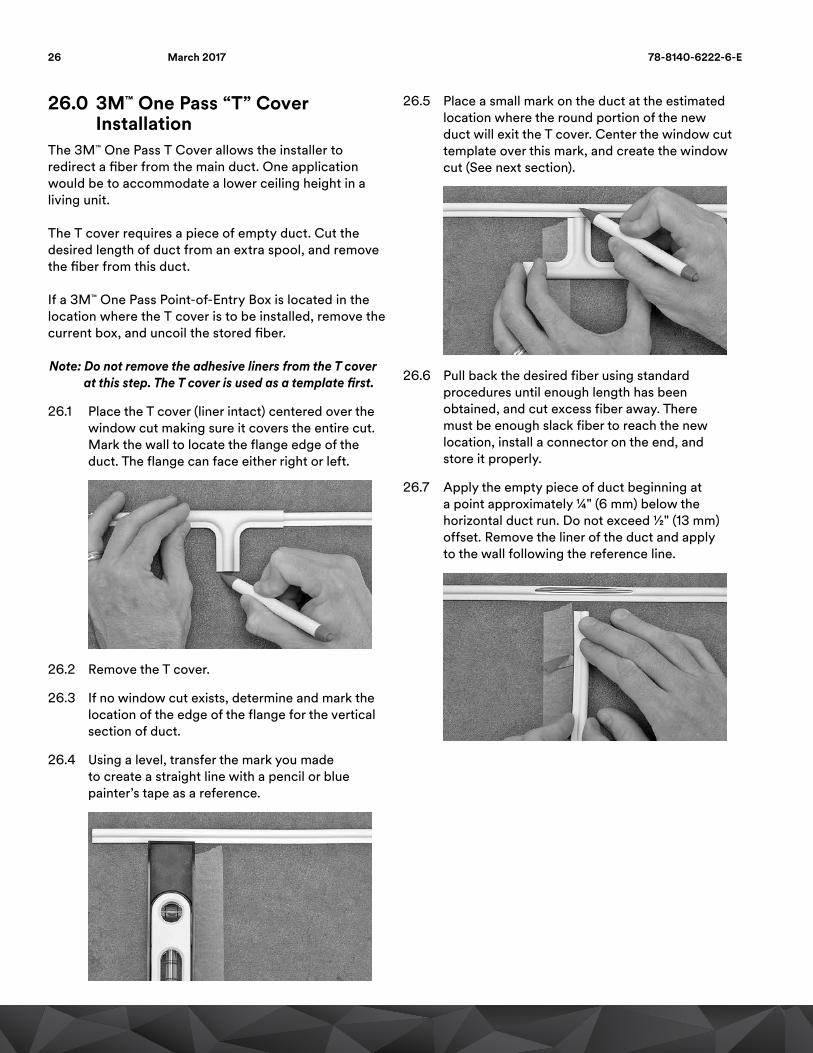
26.1 Place the T cover (liner intact) centered over the window cut making sure it covers the entire cut. Mark the wall to locate the flange edge of the duct. The flange can face either right or left.
26.2 Remove the T cover.
26.3 If no window cut exists, determine and mark the location of the edge of the flange for the vertical section of duct.
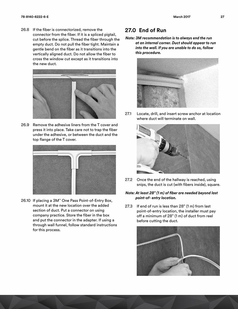
26.4 Using a level, transfer the mark you made to create a straight line with a pencil or blue painter’s tape as a reference.
26.5 Place a small mark on the duct at the estimated location where the round portion of the new duct will exit the T cover. Center the window cut template over this mark, and create the window cut (See next section).
26.6 Pull back the desired fiber using standard procedures until enough length has been obtained, and cut excess fiber away. There must be enough slack fiber to reach the new location, install a connector on the end, and store it properly.
26.7 Apply the empty piece of duct beginning at a point approximately ¼" (6 mm) below the horizontal duct run. Do not exceed ½" (13 mm) offset. Remove the liner of the duct and apply to the wall following the reference line.
26 78-8140-6222-6-EMarch 2017
26.8 If the fiber is connectorized, remove the connector from the fiber. If it is a spliced pigtail, cut before the splice. Thread the fiber through the empty duct. Do not pull the fiber tight. Maintain a gentle bend on the fiber as it transitions into the vertically aligned duct. Do not allow the fiber to cross the window cut except as it transitions into the new duct.
26.9 Remove the adhesive liners from the T cover and press it into place. Take care not to trap the fiber under the adhesive, or between the duct and the top flange of the T cover.
26.10 If placing a 3M™ One Pass Point-of-Entry Box, mount it at the new location over the added section of duct. Put a connector on using company practice. Store the fiber in the box and put the connector in the adapter. If using a through wall funnel, follow standard instructions for this process.
27.0 End of RunNote: 3M recommendation is to always end the run
at an internal corner. Duct should appear to run into the wall. If you are unable to do so, follow this procedure.
27.1 Locate, drill, and insert screw anchor at location where duct will terminate on wall.
27.2 Once the end of the hallway is reached, using snips, the duct is cut (with fibers inside), square.
Note: At least 28" (1 m) of fiber are needed beyond last point-of- entry location.
27.3 If end of run is less than 28" (1 m) from last point-of-entry location, the installer must pay off a minimum of 28" (1 m) of duct from reel before cutting the duct.
2778-8140-6222-6-E March 2017

27.4 Identify upstream point-of-entry location, make window cut and mark hole locations (See section 28).
27.5 Snip end of duct to length, ensuring a square cut of the duct.
27.6 Screw flange.
27.7 Using the fiber pick tool, pull all fibers back to be later stored in Point-of-Entry Box.
28.0 Sealing End of DuctItems Required: Caulk, filler (i.e., small piece of paper, tissue, paper towel, etc.)
28.1 Insert filler material into end of duct.
28.2 With filler material inside duct, apply caulk over the end of the duct opening.
28 78-8140-6222-6-EMarch 2017
Steps for Accessing Fiber and Installing 3M™ One Pass Surface-Mount Point-of- Entry Box29.0 Window Cut PlacementItems Required: 3M™ One Pass Window Cut Template, 3M™ One Pass Window Cut Tool, snips, 3M™ Crimplok™+ Connectors & Termination Kit or 3M™ No Polish Connectors & Termination Kit
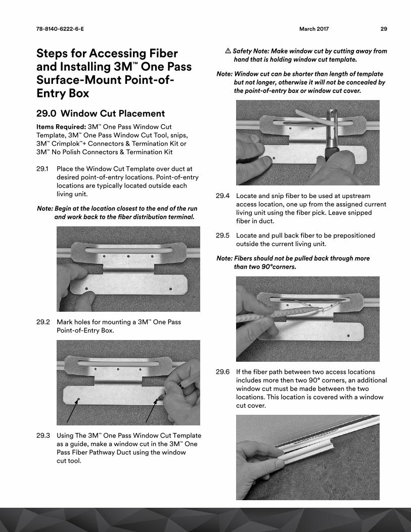
29.1 Place the Window Cut Template over duct at desired point-of-entry locations. Point-of-entry locations are typically located outside each living unit.
Note: Begin at the location closest to the end of the run and work back to the fiber distribution terminal.
29.2 Mark holes for mounting a 3M™ One Pass Point-of-Entry Box.
29.3 Using The 3M™ One Pass Window Cut Template as a guide, make a window cut in the 3M™ One Pass Fiber Pathway Duct using the window cut tool.
m Safety Note: Make window cut by cutting away from hand that is holding window cut template.
Note: Window cut can be shorter than length of template but not longer, otherwise it will not be concealed by the point-of-entry box or window cut cover.
29.4 Locate and snip fiber to be used at upstream access location, one up from the assigned current living unit using the fiber pick. Leave snipped fiber in duct.
29.5 Locate and pull back fiber to be prepositioned outside the current living unit.
Note: Fibers should not be pulled back through more than two 90°corners.
29.6 If the fiber path between two access locations includes more then two 90° corners, an additional window cut must be made between the two locations. This location is covered with a window cut cover.
2978-8140-6222-6-E March 2017
30.0 Point-of-Entry Box InstallationItems Required: 3M™ One Pass Point-of-Entry Boxes, screws, drill, 3/16" (5 mm) drill bit, adapters
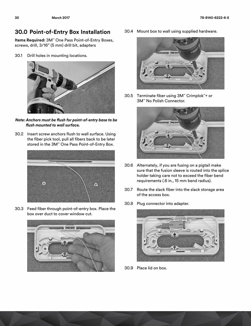
30.1 Drill holes in mounting locations.
Note: Anchors must be flush for point-of-entry base to be flush mounted to wall surface.
30.2 Insert screw anchors flush to wall surface. Using the fiber pick tool, pull all fibers back to be later stored in the 3M™ One Pass Point-of-Entry Box.
30.3 Feed fiber through point-of-entry box. Place the box over duct to cover window cut.
30.4 Mount box to wall using supplied hardware.
30.5 Terminate fiber using 3M™ Crimplok™+ or 3M™ No Polish Connector.
30.6 Alternately, if you are fusing on a pigtail make sure that the fusion sleeve is routed into the splice holder taking care not to exceed the fiber bend requirements (.6 in., 15 mm bend radius).
30.7 Route the slack fiber into the slack storage area of the access box.
30.8 Plug connector into adapter.
30.9 Place lid on box.
30 78-8140-6222-6-EMarch 2017
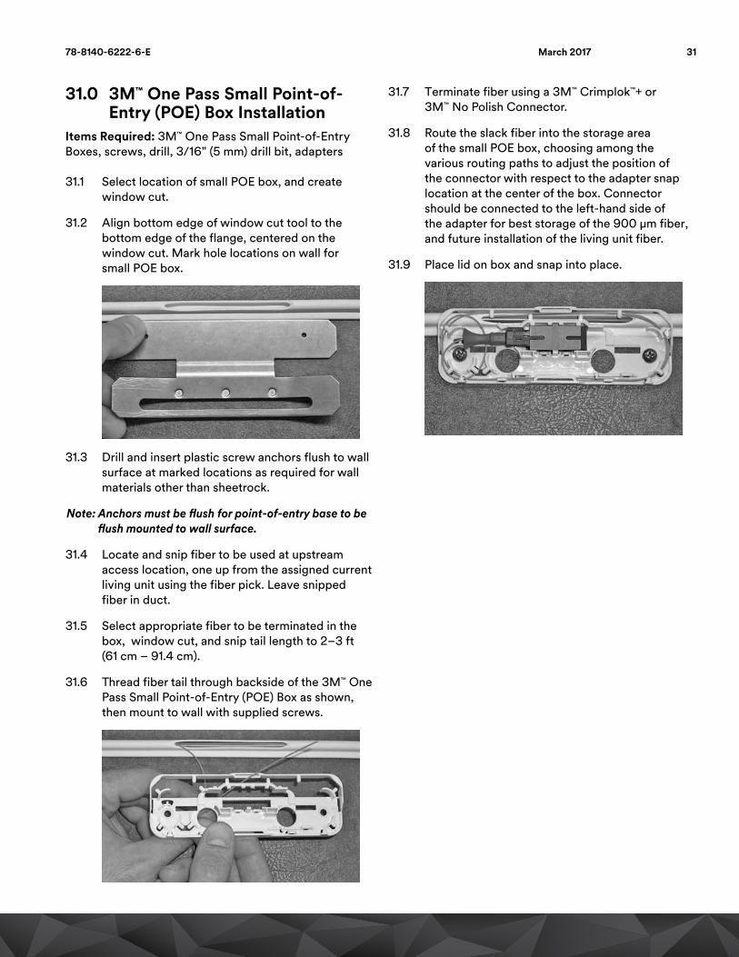
31.0 3M™ One Pass Small Point-of-Entry (POE) Box Installation
Items Required: 3M™ One Pass Small Point-of-Entry Boxes, screws, drill, 3/16" (5 mm) drill bit, adapters
31.1 Select location of small POE box, and create window cut.
31.2 Align bottom edge of window cut tool to the bottom edge of the flange, centered on the window cut. Mark hole locations on wall for small POE box.
31.3 Drill and insert plastic screw anchors flush to wall surface at marked locations as required for wall materials other than sheetrock.
Note: Anchors must be flush for point-of-entry base to be flush mounted to wall surface.
31.4 Locate and snip fiber to be used at upstream access location, one up from the assigned current living unit using the fiber pick. Leave snipped fiber in duct.
31.5 Select appropriate fiber to be terminated in the box, window cut, and snip tail length to 2–3 ft (61 cm – 91.4 cm).
31.6 Thread fiber tail through backside of the 3M™ One Pass Small Point-of-Entry (POE) Box as shown, then mount to wall with supplied screws.
31.7 Terminate fiber using a 3M™ Crimplok™+ or 3M™ No Polish Connector.
31.8 Route the slack fiber into the storage area of the small POE box, choosing among the various routing paths to adjust the position of the connector with respect to the adapter snap location at the center of the box. Connector should be connected to the left-hand side of the adapter for best storage of the 900 μm fiber, and future installation of the living unit fiber.
31.9 Place lid on box and snap into place.
3178-8140-6222-6-E March 2017

Future Tasks32.0 Service Connection 3M™ One
Pass Small Point-of-Entry (POE) Box
32.1 Remove lid to gain access to the internal portions of the Point-of-Entry (POE) Box. Select a drill location and drill access hole into living unit through one of the two holes in the base of the POE box.
32.2 From the living unit side insert the living unit fiber, terminate the fiber with 3M™ Crimplok+ or No Polish SC/APC connectors if needed.
32.3 Route and anchor 900 μm fiber with furcation tubing, route as shown, anchoring tubing in same position as jumper fibers.
3 mm Furcation Tubing Shown
32.4 Route and anchor jumper in small POE box as shown for various jumper sizes. NOTE that there is no slack storage for 3 mm or 5 mm jumper sizes.
3 mm Jacketed Cable
5 mm Jacketed Cable (Clear Curve)
32.5 Plug connector into adapter to connect service, then snap adapter back into place in center section of box.
32.6 Place lid over base and snap into place.
32 78-8140-6222-6-EMarch 2017
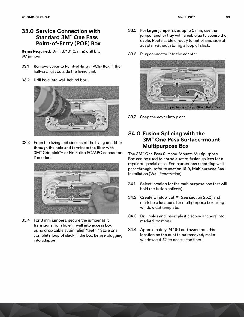
33.0 Service Connection with Standard 3M™ One Pass Point-of-Entry (POE) Box
Items Required: Drill, 3/16" (5 mm) drill bit, SC jumper
33.1 Remove cover to Point-of-Entry (POE) Box in the hallway, just outside the living unit.
33.2 Drill hole into wall behind box.
33.3 From the living unit side insert the living unit fiber through the hole and terminate the fiber with 3M™ Crimplok™+ or No Polish SC/APC connectors if needed.
33.4 For 3 mm jumpers, secure the jumper as it transitions from hole in wall into access box using drop cable strain relief “teeth.” Store one complete loop of slack in the box before plugging into adapter.
33.5 For larger jumper sizes up to 5 mm, use the jumper anchor tray with a cable tie to secure the cable. Route cable directly to right-hand side of adapter without storing a loop of slack.
33.6 Plug connector into the adapter.
Jumper Anchor Tray Strain Relief Teeth
33.7 Snap the cover into place.
34.0 Fusion Splicing with the 3M™ One Pass Surface-mount Multipurpose Box
The 3M™ One Pass Surface-Mounts Multipurpose Box can be used to house a set of fusion splices for a repair or special case. For instructions regarding wall pass through, refer to section 16.0, Multipurpose Box Installation (Wall Penetration).
34.1 Select location for the multipurpose box that will hold the fusion splice(s).
34.2 Create window cut #1 (see section 25.0) and mark hole locations for multipurpose box using window cut template.
34.3 Drill holes and insert plastic screw anchors into marked locations.
34.4 Approximately 24" (61 cm) away from this location on the duct to be removed, make window cut #2 to access the fiber.
3378-8140-6222-6-E March 2017

34.5 Cut all 12 fibers at window cut #2, and pull excess fiber back through window #1.
34.6 Pull excess fiber out of the way, and cut the duct at the edge of window cut #1 with a sheath knife, or other sharp cutter.
34.7 If removing damaged duct section, initiate and peel that section starting with window cut #1 to the desired location. Wall can be scribed on top and bottom edges of duct to reduce the amount of damage done to the wall during removal if necessary.
34.8 Discard duct that has been removed from wall.
34.9 Insert the 12 fiber tails from window cut #1 into multipurpose box from the backside of the box, and mount multipurpose box onto duct with supplied screws.
34.10 Wrap fiber tails into 3M™ One Pass Surface-Mount Multipurpose Box for storage.
34.11 Snap lid onto multipurpose box.
34.12 Wall repair can now be completed per normal practice. Any material that the duct removes should be filled back in to create a flat surface before painting and new duct installation.
34.13 After wall repair is complete, remove the Multipurpose Box lid at end of installed duct and uncoil fiber tails. Tape fiber tails to wall away from working area.
34.14 Remove multipurpose anchor screws and box from wall. Store box, lid, and screws for later use.
34.15 Install new section of duct using standard procedures. Apply duct to a location even with the closest multipurpose box anchor to that side.
34.16 Cut duct with 24" (61 cm) excess length to obtain fiber slack.
34 78-8140-6222-6-EMarch 2017

34.17 Make a window cut, aligning the outer edge of the cut with the Multipurpose Box anchor. Make sure window cut will be within the footprint of the multipurpose box.
34.18 Pull back excess fiber tails, and cut excess duct away without damaging fibers.
34.19 Place and hold the fusion splice holder and template behind the Multipurpose Box, aligning the screw holes. Thread all fibers through back of multipurpose box on each side of splice base.
34.20 Mount multipurpose box and fusion holder template to wall.
34.21 Fiber is ready for splicing. Complete per company practice, or store excess fiber in multipurpose box.
34.22 Upon completion of splicing and storing fiber, snap lid into place.
35.0 Fiber Maintenance35.1 Option 1: Use a spare fiber. Each floor should
be engineered with fiber counts that exceed the number that are required for each floor. In the event of a fiber cut, one of the spare fibers can be put into service.
35.2 Option 2: If the break is near the connector there is enough stored slack in the 3M™ One Pass Point-of-Entry (POE) Box to do additional terminations.
35.3 Option 3: If an additional length of fiber is required, splice to one of the unused ends (colors) and gain the additional fiber needed. For example: In the system when the blue fiber is used (the first apartment on the floor coming from the fiber distribution terminal). The blue fiber is cut dead to the field at the second POE. The blue fiber from the cut point to the end is left unused. Splice the broken fiber to the unused blue fiber to reach the living unit desired. This splice can be done along the length of the duct and concealed by a window cut cover.
FiberDistribution
Terminal
GreenGreenOrangeOrange
BlueBlue
Damaged Green FiberDamaged Green Fiber
Splice to the unused blue fiber
3578-8140-6222-6-E March 2017

Communication Markets Division6801 River Place Blvd.Austin, TX 78726-9000
Phone 1-800-426-8688Web www.3M.com/Telecom
Please recycle. Printed in USA © 3M 2017. All rights reserved. 78-8140-6222-6-E
3M, Crimplok and ScotchBlue are trademarks of 3M Company.
Important NoticeAll statements, technical information, and recommendations related to 3M’s products are based on information believed to be reliable, but the accuracy or completeness is not guaranteed. Before using this product, you must evaluate it and determine if it is suitable for your intended application. You assume all risks and liability associated with such use. Any statements related to the product which are not contained in 3M’s current publications, or any contrary statements contained on your purchase order shall have no force or effect unless expressly agreed upon, in writing, by an authorized officer of 3M.
Warranty; Limited Remedy; Limited Liability. This product will be free from defects in material and manufacture for a period of one (1) year from the time of purchase. 3M MAKES NO OTHER WARRANTIES INCLUDING, BUT NOT LIMITED TO, ANY IMPLIED WARRANTY OF MERCHANTABILITY OR FITNESS FOR A PARTICULAR PURPOSE. If this product is defective within the warranty period stated above, your exclusive remedy shall be, at 3M’s option, to replace or repair the 3M product or refund the purchase price of the 3M product. Except where prohibited by law, 3M will not be liable for any direct, indirect, special, incidental or consequential loss or damage arising from this 3M product, regardless of the legal theory asserted.