
ALARM MONITORING SERVICE INTRUSION ALARM, FIRE ALARM, EMERGENCY CALL.

798951.10.GB0 G 299044
03.2012 G 205129
Technical changes reserved!
© 2012 Honeywell International Inc.
GB
Installation Instruction
Fire Alarm Control Panel IQ8Control C/M

Fire Alarm Control Panel IQ8Control C/M
2 FB 798951.10.GB0 / 03.12
Intended purpose
This product must only be used for the applications outlined in the catalogue and the technical description and in combination with external components and systems which have been approved or recommended by Esser by Honeywell.
Warning
In order to ensure correct and safe operation of the product, all guidelines concerning its transport, storage, installation, and mounting must be observed. This includes the necessary care in operating the product.
Safety-relevant user information
This manual includes all information required for the proper use of the products described.
The term 'qualified personnel' in the context of the safety information included in this manual or on the product itself designates:
• project engineers who are familiar with the safety guidelines concerning fire alarm and extinguishing systems.
• trained service engineers who are familiar with the components of fire alarm and extinguishing systems and the information on their operation as included in this manual.
• trained installation or service personnel with the necessary qualification for carrying out repairs on fire alarm and extinguishing systems or who are authorised to operate, ground and label electrical circuits and/or safety equipment/systems.
Safety warnings
The following information is given in the interest of your personal safety and to prevent damage to the product described in this manual and all equipment connected to it. Safety information and warnings for the prevention of dangers putting at risk the life and health of user and maintenance personnel as well as causing damage to the equipment itself are marked by the following pictograms. Within the context of this manual, these pictograms have the following meanings:
Designates risks for man and/or machine. Non-compliance will create risks to man and/or machine. The level of risk is indicated by the word of warning.
Important information on a topic or a procedure and other important information!
§
Observe configuration and commissioning information in accordance to the national and local requirements.
Dismantling
In accordance with Directive 2002/96/EG (WEEE), after being dismantled, electrical and electronic equipment is taken back by the manufacturer for proper disposal.

Fire Alarm Control Panel IQ8Control C/M
FB 798951.10.GB0 / 03.12 3
1 Installation Instruction................................................................................................................................................. 5
2 System overview........................................................................................................................................................ 8
3 Configuration options................................................................................................................................................. 9
3.1 Special configuration – Swiss option CH ....................................................................................................... 10 3.2 FACP IQ8Control C........................................................................................................................................... 11 3.3 FACP IQ8Control M........................................................................................................................................... 13 3.4 Definition of the Primary loop number.............................................................................................................. 18 3.5 Central housing.................................................................................................................................................. 20 3.6 Assembly............................................................................................................................................................ 21 3.7 Cable glands ...................................................................................................................................................... 26 3.8 Panel buzzer ...................................................................................................................................................... 26
4 Module ...................................................................................................................................................................... 27 4.1 Power supply module (Part No. 802426 index G or higher)........................................................................... 27
4.1.1 Mains connection and earth connections .................................................................................... 29 4.1.2 Protective and Functional earth................................................................................................... 30 4.1.3 Emergency power supply ............................................................................................................ 31 4.1.4 Allowable types of batteries......................................................................................................... 31 4.1.5 Specification Power supply module (Part No. 802426) ............................................................... 34
4.2 Basic module...................................................................................................................................................... 35 4.3 Software.............................................................................................................................................................. 38
4.3.1 Firmware Update ......................................................................................................................... 38 4.3.2 Customer data programming....................................................................................................... 40 4.3.3 Housing contact ........................................................................................................................... 41 4.3.4 Serial interface............................................................................................................................. 42 4.3.5 Micro module slot......................................................................................................................... 45 4.3.6 Technical data Basic module....................................................................................................... 46
4.4 Field device module........................................................................................................................................... 47 4.4.1 Connecting a fire department operating panel ............................................................................ 51 4.4.2 Connecting the master box (Relay K1)........................................................................................ 52 4.4.3 Connecting the Relays K2, K3, K4 .............................................................................................. 56 4.4.4 Technical data Field device module ............................................................................................ 58
4.5 Extension module .............................................................................................................................................. 59 4.5.1 Technical Data Extension module ............................................................................................... 60
5 Micro module............................................................................................................................................................ 62 5.1 Loop modules..................................................................................................................................................... 62
5.1.1 esserbus® loop module (Part No. 784382 / 784382.10 / 784382.D0).......................................... 64 5.1.2 esserbus®-PLus loop module (Part No. 804382 / 804382.10 / 804382.D0)................................ 65 5.1.3 Technical Data loop module ........................................................................................................ 68
5.2 essernet® module............................................................................................................................................... 69 5.2.1 essernet® micro module (Part No. 784840 / 784840.10 and 784841 / 784841.10) .................... 70 5.2.2 Technical data essernet® micro module ...................................................................................... 72 5.2.3 Important installation instructions of essernet® micromodules .................................................... 74
6 Relay module............................................................................................................................................................ 76 6.1 3-relay module / 3-relay common trouble module........................................................................................... 76 6.2 4- Relay module................................................................................................................................................. 81
6.2.1 Technical Data Relay module...................................................................................................... 83 6.3 Serial interface module...................................................................................................................................... 84
6.3.1 RS 232 / TTY module .................................................................................................................. 84 6.3.2 Technical data interface modules................................................................................................ 86

Fire Alarm Control Panel IQ8Control C/M
4 FB 798951.10.GB0 / 03.12
7 Master box activation module ................................................................................................................................. 87 7.1 Technical Data Master box activation module (Part No. 784385) ................................................................. 91 7.2 Overview – micro module terminals................................................................................................................. 92
8 Installer level............................................................................................................................................................. 96
9 Diagnostic display .................................................................................................................................................. 108 9.1 Diagnostic display IQ8Control C/M ................................................................................................................ 108 9.3 Checking the essernet® devices and connections........................................................................................ 111
9.3.1 Checking the essernet® devices and connections..................................................................... 112
10 Meaning of the three digit error codes / test mode.............................................................................................. 116
11 Functionality for fire alarm control panels............................................................................................................. 126 11.1 Use of the loop module in door control systems ........................................................................................... 126
12 IQ8Wireless............................................................................................................................................................ 127
13 Top hat rail mounting kit (Part No. 788652) ......................................................................................................... 129
14 esserbus® transponder.......................................................................................................................................... 131
15 Extension housing.................................................................................................................................................. 132 15.1 Extension housing for two batteries (Part No. 789300 / -01)........................................................................ 134
16 Power supply for the built-in printer ...................................................................................................................... 135
17 Mounting / Replacing of the Panel front + Printer................................................................................................ 136 17.1 Heat transfer Printer without paper take-up unit (Part No. 7868xx / 7869xx)............................................. 136 17.2 Printer with paper take-up reel (Part No. 7863xx)......................................................................................... 139
18 Fire protection housing F30 .................................................................................................................................. 141
Additional and updated Informations The described features, specifications and product related informations in this manual correspond to the date of issue (refer to date on the front page) and may differ due to modifications and/or amended Standards and Regulations of the System design, Installation and Commissioning. Updated informations and declaration of conformity are available for comparison on the www.esser-systems.de homepage.
esserbus® and essernet® are registered trademarks in Germany.

Fire Alarm Control Panel IQ8Control C/M
FB 798951.10.GB0 / 03.12 5
1 Installation Instruction Operation of the Fire Alarm Control Panel IQ8Control is governed by the national version of the operating system software used and the country version programmed in the customer data. The terminal assignment and wiring illustrated in these installation instructions refer exclusively to the facilities of the operating system software for the Federal Republic of Germany D .
• The fire alarm panel may only be installed in a dry, clean room with controlled access and appropriate lighting. The environmental conditions must comply with DIN EN 60721-3-3, class 3k5.
• The panel must be mounted on a flat surface using appropriate hardware (screws and dowels). Avoid mechanical stressing. It may only be commissioned after correct mounting on a wall or other mounting surface of sufficient strength to support the weight of the unit.
• Avoid strong electric or magnetic fields as well as mechanical influences. This applies especially to the presence of fluorescent lighting or energy cabling in the close vicinity of the panel, its components and the associated cabling. Do not mount on vibrating, unstable surfaces such as light partitioning walls.
• Do not install the system in places where adverse conditions prevail. Parts and components of the system may only be installed in or led through locations which allow compliance with DIN VDE 0800.
• Control panels and visual indicators mounted on a wall should be installed at a height of 800 to 1800 mm above the floor.
• The fire alarm system is not suitable for connection to IT power supply systems.
• It is highly recommended for correct ESD protection that the dummy plug (factory supplement) of the programming interface plug is inserted into the front of the operation panel.
This documentation applies to the following products:
• Fire Alarm Control Panel IQ8Control C/M
• Standard system software (without special customer-dependent functionality)
• Country function >Germany<

Fire Alarm Control Panel IQ8Control C/M
6 FB 798951.10.GB0 / 03.12
Configuration and Commissioning
For the configuration and commissioning of the system, the programming software tools 8000 is required in each case in the current program version.
Installer / Installation Specialist
The fire alarm control panel must be installed by a skilled electrician (according to DIN VDE 0833), who, as a result of the appropriate training and experience, can evaluate the work to be carried out and recognise potential dangers. In addition to the specialist qualifications, knowledge of the validity and application of the relevant standards and their use and compliance with is required.
Operator of the Fire Alarm System / Trained Person
For the operation of the fire alarm control panel, a qualified person must be trained in the basic functioning of the system and its technical requirements. A trained person (according to DIN VDE 0833) must be able to operate the fire alarm control panel and to recognise faults. If a fault signal occurs or the functionality is limited, arrangements must be made for the checking and rectification of the cause of the fault.
Maintenance / Service
Maintenance is necessary for the proper operation of the fire alarm control panel. The function of the system parts can be affected by environmental conditions and ageing. For an application within the area of validity of the European Union (EU) the maintenance is defined in EN 54. In addition to the safety directives and notes in this documentation, the country-specific requirements for the operational location of the fire alarm control panel must be observed.
Danger – Electrical shock ! Remove all power from the panel before carrying out any installation work! ESD protection While handling electronic assemblies, the necessary precautions against electrostatic discharge must be taken. Protective and functional earth The PE conductor must be connected to the corresponding terminal at the mains supply. Connect the FE terminal of the panel’s cabinet with the PE rail of the power distributor panel from which the fire alarm system will be powered.
Commissioning A complete system check must be carried out after commissioning and for each modification of the customer data programming!
1.1 Approval Specification : EN 54-2 : 1997 / A1 : 2006
VdS approval : G 299044 and G 205129
CE certificate : 0786-CPD-20827

Fire Alarm Control Panel IQ8Control C/M
FB 798951.10.GB0 / 03.12 7
1.2 Standards and guidelines The general technical rules must be observed when installing fire alarm systems. Any deviation from those rules is only admissible if the same degree of safety can be ensured with different means. Installations within the European Community are primarily subject to all EU regulations defining the current standards for security systems. In Germany, systems are considered to be in compliance with the general technical rules or the standards of the EU for security systems if they meet the technical guidelines of the VDE (Verband Deutscher Elektrotechniker, Association of German Electrical Engineers). They may also be considered to be in compliance with the standards of the EU for security systems if they meet the technical guidelines of another comparable institution within the European Community which have been accepted in accordance with directive on low-voltage systems (2006/95/EG). The same must be applied for all applications of additional, product relating guidelines, e.g. EMI-Guideline 2004/108/EG and the Construction Products Directive (CPD) 89/106/EG. These are examples: • Standards of the DIN EN 54 “Fire alarm systems“, particulary DIN EN 54-2 „Fire alarm control panels" and
DIN EN 54-4 „Power supply units". • Standards of the DIN VDE 0100 issue, particulary DIN EN 0100-410 „Installation of high-voltage sytems
with rated voltage up to 1000 V“, DIN VDE 100-718, Install low voltage systems – Requirements for sites, rooms and special systems and DIN VDE 0105-100 „Operation of electrical system: General commitments“.
• Standards of the DIN EN 62305 or DIN VDE 0185-305 issue, particulary DIN VDE 0185-305-1 „Lightning protection: General standards. DIN VDE 0185-305-2 „Risk-Management“, DIN VDE 0185-305-3 „Protection of buildings and persons“ and DIN VDE 0185-305-4 „Eletrical and electronic systems in buildings“.
• DIN VDE 0701-1 „Maintenance, Modification and Test of electrical devices: General commitments“. • Standards of the DlN VDE 0800 issue, particulary DIN VDE 0800-1 „General commitments, Requirements
and Tests for system security“, DIN VDE 0800-1 „Communication systems, Earthing and potential compensation“, DIN VDE 0800-174-2 .Information systems – design and installation of communication cabling in buildings“.
• DIN VDE 0815 „Cables for communication and information systems“. • Standards of the DIN VDE 0833 issue Hazard alarm systems for Fire, Intruder and Hold-up, particulary DIN
VDE 0833-1 „General commitments“, DIN VDE 0833-2 „Commitments for fire alarm systems (FAS)“, DIN VDE 0833-3 „Commitments for Intruder and Hold-up systems“ and DIN VDE 0833-4 „Commitments for Voice alarm systems within fire protection“.
• Standards of the DIN VDE 0845 issue, particulary DIN VDE 0845-1 „Protection of Communication systems against Lightning, electrostatic charge and overvoltage from high-voltage systems; Actions to avoid over-voltage“.
• DIN 14675 Fire alarm systems – mounting and operation. These technical guidelines must be observed within the European Community. The VDE guidelines must be observed within Germany. In other countries (e.g. U.S.A.: NFPA and UL requirements), the relevant national standards, guidelines and legislation must be observed. The requirements of the local fire departments and competent authorities must also be complied with. In addition to the above, the guidelines of the German VdS Schadenverhütung GmbH (VdS) may apply for systems installed in Germany. • VdS 2046 Safety rules for electrical power systems with voltages up to 1000 V. • VdS 2015 Electrical appliances and systems – rules for damage prevention. • VdS 2095 Design and installation of fire alarm systems. • VdS 2833 Overvoltage protection measures for Hazard Alarm Systems. • Always observe national and local building law requirements and regulations (building regulations).

Fire Alarm Control Panel IQ8Control C/M
8 FB 798951.10.GB0 / 03.12
2 System overview The modular design with different micro modules and individual extension concepts allow the Fire Alarm Computer IQ8Control C and IQ8Control M to be easily adapted to special requirements. This provides the range from a stand-alone panel up to 31 Fire Alarm Control Panels Computer or other network subscribers such as hazard management system, Fire department indicator panel or Intruder Alarm Panels Series 5000 by using the essernet® safety network. The Field device modules required in order to configure a stand-alone FACP in accordance to the appropriate standards and guidelines. The connections for the Fire Alarm Control Panel, the master box and the three freely programmable relays are integrated on the Field device module. If several Fire Alarm Control Panels are connected together in the essernet®, the master box can be connected to one of the other FACPs.
essernet®
max. 1 km
max. 1 km
Repeater
max. 1 km
esserbus®-PLus
LWL
LWL
Hazard management system
Fire departmentindicator panel
FDOPLCD
display panelFire dept. key box
TALmoduleMFAB
Fire alarm and extinguishingcomputer 8010
Serial essernet®-Interface
Fibre optical cable
Fig. 1: System overview
Additional extensions
The FACP panel configuration may be extended to suit requirements by adding supplementary input/ output modules, esserbus® transponders. Transponders may be installed at special integrated slots or on standard C-Top rails in the housing. Optional plastic housings conforming to protection class IP 40 are available for the decentralized installation of transponders on the loop.

Fire Alarm Control Panel IQ8Control C/M
FB 798951.10.GB0 / 03.12 9
3 Configuration options The operating module front (7860xx) is available in various language versions. The language is defined with the 2-digits of the part number, e.g. 786002 = English lettering.
IQ8Control C IQ8Control M
Operating module
7860_ _
---
7861_ _
---
7868_ _
---
7864_ _
---
7865_ _
---
7869_ _
---
742100
786000
1) --- 2)
7863_ _
1)
Extension housing 789304
Fig. 2: Configuration options 1) Extension housing required 2) Not available for operating module 7861 _ _ or 7865 _ _

Fire Alarm Control Panel IQ8Control C/M
10 FB 798951.10.GB0 / 03.12
3.1 Special configuration – Swiss option CH
IQ8Control C IQ8Control M
Operating module
786261
---
786262
---
786263
--- Fig. 3: Operating module – Swiss CH with integrated Fire department operating panel (FBA)
For country-specific displays and labels as well as further information CH refer to operating instructions FACP IQ8Control C/M (Part No. 798950.10.GB0).

Fire Alarm Control Panel IQ8Control C/M
FB 798951.10.GB0 / 03.12 11
3.2 FACP IQ8Control C
The configuration of the FACP IQ8Control C includes: • 1 Basic module
• 1 Power supply module
• 1 Field device module or 1 Extension module In the full configuration, two freely selectable micro modules can be employed.
On the Basic module only the upper slot (slot 1) of can be
used for a Field device or Extension module.
The lower slot (slot 2) of the FACP IQ8Control C is not used.
Micro module
Power supply module Part No. 802426
A Field device module Part No. 772479
B Field device module with one micro module slot Part No. 772477C
onne
ctor
1
A B C
1
2
C Extension module with one micro module slot Part No. 772478
Fig. 4: Configuration FACP IQ8Control C

Fire Alarm Control Panel IQ8Control C/M
12 FB 798951.10.GB0 / 03.12
Configuration of FACP IQ8Control C
Con
nect
or 1
MM 1
A
Example 1:
Basic module with a micro module and a Field device module (Part No.772479 without micro module slot) on slot 1 of the Basic module.
Application:
With this configuration, for example, a single control panel with an loop and max. 127 bus devices can be implemented.
Con
nect
or 1
MM 1
MM 2
B
Example 2:
Basic module with a micro module and a Field device module (Part No.772477 with micro module slot) on slot 1 of the Basic module
Application:
With this configuration, for example, a single control panel with two loops and max. 254 bus devices can be implemented or This configuration is usually employed in essernet® networks with an loop and max. 127 bus devices.
Example 3:
Basic module with a micro module and a Extension module (Part No.772478 ) on slot 1 of the Basic module.
Application:
This configuration is usually employed in essernet® networks with an loop and max. 127 bus devices.
C
Con
nect
or 1
MM 1
MM 2
Without the Field device module, no connection is available for the fire department key pad and the master box. These devices can be connected to a different control panel of the essernet®.
Fig. 5: Configuration FACP IQ8Control C

Fire Alarm Control Panel IQ8Control C/M
FB 798951.10.GB0 / 03.12 13
3.3 FACP IQ8Control M
The configuration of the FACP IQ8Control C includes:
• 1 Basic module
• 1 Power supply module
• 1 Field device module or 1 Extension module 1
or
• max. 2 Extension modules - each with three micro module slots
In this full configuration, a total number of slots for 7(3 + 3 + 1) freely selectable micro module are available.
Slot 1
On the Basic module only the upper slot (slot 1) can be used for a Field device or Extension module. The Field device module must be installed in Slot 1 of the Basic module.
Slot 2
The lower slot (slot 2) can be used for a Extension module only.
A Field device module Part No.772479
B Field device module with one additional micro module slots Part No.772477
C Extension module with one additional micro module slots Part No.772478
Con
nect
or 1
Con
nect
or 2
A B C1
2D
D
D Extension module with three additional micro module slots
Part No.772476
Fig. 6: Configuration FACP IQ8Control M

Fire Alarm Control Panel IQ8Control C/M
14 FB 798951.10.GB0 / 03.12
Example: Configuration of FACP IQ8Control M
Example 1:
Basic module with a Field device module (without micro module slot) on slot 1 and one Extension module (with 3 micro module slots) on slot 2.
Application:
With this configuration, e.g. a single control panel with 4 loops and max. 508 bus devices can be implemented.
A
Field device module (Part No.772479)
Con
nect
or 2
MM 1 A
D
MM 2
MM 3
MM 4C
onne
ctor
1
D
Extension module with three additional micro module slots (Part No.772476)
Example 2:
Basic module with a Field device module (without micro module slot) on slot 1 and one Extension module (with 3 micro module slots) on slot 2.
Application:
With this configuration, e.g. a single control panel with 5 loops and max. 635 bus devices can be implemented
B
Field device module with 1 additional micro module slot (Part No.772477)
MM 1
MM 2
B
D
MM 3
MM 4
MM 5
Con
nect
or 2
Con
nect
or 1
D
Extension module with three additional micro module slots (Part No.772476)
Fig. 7: Configuration FACP IQ8Control M

Fire Alarm Control Panel IQ8Control C/M
FB 798951.10.GB0 / 03.12 15
Example: Configuration of FACP IQ8Control M
Example 3:
Basic module with a Field device module (without micro module slot) on slot 1 and one Extension module (with 3 micro module slots) on slot 2.
Application:
With this configuration, e.g. a security network panel with 4 loops and max. 508 bus devices can be implemented.
C
Extension module with one additional micro module slot (Part No.772478)
MM 1
MM 2
C
D
MM 3
MM 4
MM 5
Con
nect
or 2
Con
nect
or 1
D
Extension module with three additional micro module slots (Part No.772476)
Example 4:
Basic module with two Extension modules (with 3 micro module slots) on slot 1 + 2.
Application:
With this configuration, e.g. a security network panel with 6 loops and max. 762 bus devices can be implemented.
D
Extension module with three additional micro module slots (Part No.772476)
MM 1
D
MM 5
MM 6
MM 7
D
MM 2
MM 3
MM 4
Con
nect
or 2
Con
nect
or 1
Fig. 8: Configuration FACP IQ8Control M
Do not install Field device and Extension modules series 01 FACP 8000 C/M (Part No. 772418, 772419, 772420, 772421) at FACP IQ8Control C/M.

Fire Alarm Control Panel IQ8Control C/M
16 FB 798951.10.GB0 / 03.12
Three part housing with integrated printer
The integrated printer and the operating module front are mounted in the upper housing. Due to the depth of the printer, the Basic module and all of the plug-in cards are integrated into a separate housing beneath. The emergency power supply with max. two 24Ah batteries can be installed into the lowest housings.
Extension housing 789304
or
Extension housing 789303
Fig. 9: Three part housing with integrated printer
Assembly area for esserbus® transponders
Basic module / power supply module / slot for micro module
Alternatively Field device module (without micro module slot)
or Field device module (with 1 micro module slot)
or Extension module (with 1 micro module slot)
or Extension module (with 3 micro module slots) on slot 1
Part No. 772479
Part No. 772477
Part No. 772478
Part No. 772476
1
1
3
4
2
Extension module (with 3 micro module slots) on slot 2
Part No. 772476
Fig. 10: Location of the components in a three part housing
Ensure that the arrangement of the assemblies corresponds with the presentation shown here during this configuration. Another distribution is not possible due to the cable length of the operating module front, the integrated printer and the battery connection cable.

Fire Alarm Control Panel IQ8Control C/M
FB 798951.10.GB0 / 03.12 17
Location of the components in a three part FACP housing IQ8Control M
Fig. 11: Location of the components in a three part housing
Mounting plate for master boxes DS 7500 / DS 8800
The mounting plate (Part No. 057633) allows installation of two esserbus® transponders or one master box Type DS 7500 / DS 8800 in the extension housing (Part No. 789303). Protect the devices against short circuits with the metal mounting plate with the plastic spacers and the insulation foil.
Mounting plate
Insulation foil
Fig. 12: Mounting plate (Part No. 057633)

Fire Alarm Control Panel IQ8Control C/M
18 FB 798951.10.GB0 / 03.12
3.4 Definition of the Primary loop number Individual assemblies of the FACP IQ8Control can be switched on/off with the internal primary loop number through the control panel keyboard or programmed with programming software . This internal primary loop number is composed of the control panel number, the slot and the assembly number.
Example: Stand-alone FACP (= Panel No. 01)
1
3
2
0113 0123 0133
0132
0131
Fig. 13: FACP IQ8Control
0 1 X X
Subassembly number of the Basic-, Field device or Extension module (ref. follow pages) Slot number: Basic module = No. 1 Basic module Slot 1 = No. 2 Basic module Slot 2 = No. 3 (only FACP IQ8Control M)
Number of the Fire Alarm Control Panel Stand-alone FACP = 01 Security network FACP = 01 - 31

Fire Alarm Control Panel IQ8Control C/M
FB 798951.10.GB0 / 03.12 19
Example: Primary Loop No. (Panel No. 01)
Primary Loop No. Subassembly
Position of modules
Basic module
0111 Common Fault Relay (SaS-Relay) 0112 Interface - RS485-1 or TTY 0113 Micro module slot
Con
nect
or 1
Con
nect
or 2
Field device module
0121 Relay K2, K3 and K4 0122 Master box (MB) Relay K1 0123 Micro module slot (only module Part No. 772477) 0124 Internal primary loop
Extension module with 1 micro module slot Part No. 772478 --- no module available --- no module available
0123 Micro module slot --- no module available
Con
nect
or 1
Extension module (only IQ8Control M)
with 3 micro module slots Part No. 772476
0121 Micro module slot 1 0122 Micro module slot 2 0123 Micro module slot 3
Con
nect
or 1
Extension module (only IQ8Control M)
with 3 micro module slots Part No. 772476
0131 Micro module slot 1 0132 Micro module slot 2 0133 Micro module slot 3 C
onne
ctor
2
The Field device module (if available) must be installed in >Slot 1< of the Basic module. >Slot 2< of the Basic module is unused on the FACP IQ8Control C.

Fire Alarm Control Panel IQ8Control C/M
20 FB 798951.10.GB0 / 03.12
3.5 Central housing 1. Remove the central housing of the FACP IQ8Control from the box.
The cover contact and both connecting cables for the rechargeable batteries have already been attached to the Basic module.
2. Pull the ribbon cable of the operating module and of the built-in printer (if present) off the connectors of the
Basic module.
3. Remove the four connecting screws between the base plate and the housing frame which were screwed in for transport.
4. The housing door (operating module and variants) has already been connected to the housing frame at the factory. To detach the housing door from the housing frame, pull out both retaining pins of the housing door holder.
5. The housing must be mounted on a stable, clean and dry wall surface without mechanical stress. The
function of the snap-type connection for the housing door can be impaired if the housing is not correctly mounted. Only flat-head screws and dowels with a diameter of 8 mm should be used to secure the central unit’s housing. Here, make sure that the screw head fits into the hole of the wall compensation element and does not project.
6. To compensate for slight wall unevenness, you can screw the four wall compensation pieces of the base
plate in or out. The central unit’s additional pack contains a special spanner for the adjusting the wall compensation elements. The three unused fastening points between the base plate and the housing frame are not necessary on the FACP IQ8Control C/M. This fastening is intended for a different housing use.
Danger - Electrical shock ! Disconnect all power from the panel before carrying out any installation work. The panel may only be operated while the cabinet is closed. Operation is not allowed while the cabinet is open.
Risk of short circuit All voltage and signal lines connected to the Basic module must be secured to prevent slipping by using a suitable attachment materials such as plastic cable binders. Make sure the voltage cable will not move and touch the signal lines (SELV). Work on the FACP IQ8Control may only be carried out when it is de-energised (mains and emergency power supply).

Fire Alarm Control Panel IQ8Control C/M
FB 798951.10.GB0 / 03.12 21
3.6 Assembly The housing is pre-assembled by factory delivery. To ease the further assembling and mounting please observe the given mounting sequence.
1
5
32
4
6
7
Fig. 14: Exploded illustration
4x wall compensation pieces
1 x Metal sheet of the base plate for shielding and the PE connection (functional earth)
1x rear panel
1x back box
1x housing contact (up to four contacts possible)
1x front frame with operating module and housing door
4x connecting screws
The Basic module is connected to the central housing’s rear metal panel via the metal spacers and the metal screws. Without this electrically conductive connection between the Basic module and the rear metal panel, sufficient EMC protection for the FACP IQ8Control is not guaranteed.

Fire Alarm Control Panel IQ8Control C/M
22 FB 798951.10.GB0 / 03.12
Operating module / Housing door
The operating module/the housing door is installed by the manufacturer on the front housing part. If required for dismantling, loosen the 4 fixing screws and remove the front part of the housing. Depending on the panel configuration, e.g. with or without an installed printer or an individual zone display, deviation from the illustration here is possible.
1 2 3
4 5 6
7 8 9
0
8
For correct ESD protection it is highly recommended to insert the dummy plug (insert pack) of the programming interface plug into front of the operation panel.
Fig. 15: Operating module / Housing doo
The operating module is not required for programming the FACP IQ8Control. The service PC can also be directly connected to the programming connector of the Basic module. Using the service program TEDIS (optional) enables the operating module to be completely simulated on the service PC with all functions.
Opening The front door key is always required to open the housing front. It can be opened with the key vertical
Closing To close the front door, the lock must be in the horizontal position. The key is not required. The front door can simply be pushed closed and engaged in the snap-type fastener.
Example: Housing IQ8Control C
1. Place front frame with integrated door carefully onto the back box. Take care to ensure that no cables are pinched or damaged when installing or removing the assembly.
2. Insert the four screws between the back box and the front frame and tighten carefully.
3. Insert housing contact in the upper place of the housing with the contact tab downwards. The contact is connected to the Basic module by factory settings and may be removed for service or maintenance work.
4. Connect the ribbon cable of the operation panel to the corresponding connector on the Basic module.
5. This completes assembly of the housing

Fire Alarm Control Panel IQ8Control C/M
FB 798951.10.GB0 / 03.12 23
Housing contact
The housing contact provides the monitoring of the panels housing and may be used additionally for control function by means of service or maintenance work, e.g. to disconnect devices whilst the contact is open.
1 1
11
• Max. 2 contacts per housing (1 integrated contact by factory configuration)
• Max. 4 contacts per FACP
• Select contact operation via the panels data configuration, e.g. - Disconnect master box whilst open contact - Access of Service-PC whilst open contact - und additional features
The housing contact must be place to the appropriate insert on the top corner of the housing.
• Housing contact / contact tab points downwards
X7 X8
8765
Hou
sing
con
tact
V2
Housingopen
1234
Connect to Basic module (refer to section “Basic module”)
Fig. 16: Housing contact

Fire Alarm Control Panel IQ8Control C/M
24 FB 798951.10.GB0 / 03.12
Connection between the central housing and the extension housing
1
1
1
2x connection pieces with cable glands
1. Remove the appropriate 2 plastic plates from panels and extension housing
2. Push the plastic connector bracket in each originated gap. Observe the arrows on the bracket for the right direction.
3. Push the upper housing via the guide way of the brackets towards the wall.
4. Align both connection brackets to ensure that the cables between the housings may be lead through the openings of the brackets.
5. Each housing must be fixed with suited screws (4x) and dowels without twisting stress.
Fig. 17: Knockouts for battery cable
Damage to the system! Take care to ensure that no cables are pinched or damaged. Each housing part must be separately fixed to the mounting place. The plastic connection brackets are not suited to carry the weight of the lower housing alone.

Fire Alarm Control Panel IQ8Control C/M
FB 798951.10.GB0 / 03.12 25
Wall mounting
The panel must be mounted on a flat surface using appropriate hardware (screws and dowels). Avoid mechanical stressing. It may only be commissioned after correct mounting on a wall or other mounting surface of sufficient strength to support the weight of the unit. Minor unevenness of the mounting surface may be adjusted by the wall compensation device. Apply the delivered key tool from the inside of the housing to adjust the wall compensation devices.
1 Fig. 18: Rear side of the Standard back box
Plastic key is enclosed.
Fig. 19: Wall compensation element for adjusting and key tool
Damage to the system !
Please note that depending on the rechargeable batteries used, a significant weight must be supported by the fastening screws of the extension housing.

Fire Alarm Control Panel IQ8Control C/M
26 FB 798951.10.GB0 / 03.12
3.7 Cable glands Lead the 230V main power cord through the wall and the cable entry provided in the rear of the unit (see illustration). Fasten it using appropriate devices, e.g. plastic cable straps. Make sure that the mains and signal cables don’t interfere with the rear panel of the cabinet or the cabinet frame which is mounted on the rear panel. Signal cables must only be led through the other cable entries .
IQ8Control C
21
IQ8Control M
1 2
Fig. 20: Cable glands
Danger - Electrical shock ! Disconnect all power from the panel before carrying out any installation work. The panel may only be operated while the cabinet is closed. Operation is not allowed while the cabinet is open.
Risk of short circuit All voltage and signal lines connected to the Basic module must be secured to prevent slipping by using a suitable attachment materials such as plastic cable binders. Make sure the voltage cable will not move and touch the signal lines (SELV). Work on the FACP IQ8Control may only be carried out when it is de-energised (mains and emergency power supply).
Insulation of connecting cable Make sure to lead all cables complete with their outer sheaths intact into the cabinet. Only remove the insulation from those sections which are inside the cabinet.
3.8 Panel buzzer If required the internal panel buzzer may be disabled with the solder jumper BR2 on the rear side of the operating panel PCB.
BR2
closed, buzzer enabled (factory setting)
BR2
BR2
open, buzzer disabled
If the buzzer is permanently disabled (BR2 open), the transmission of this audible warning signal to must be ensured (e.g. by indicating this condition at a panel within the network)!

Fire Alarm Control Panel IQ8Control C/M
FB 798951.10.GB0 / 03.12 27
4 Module The FACP IQ8Control C / M has a modular design so that modules can be replaced/extended at any time.
Only remove or insert modules when the FACP is voltage free. • Switch off the power and battery supply. • Wait for at least 10 seconds before the modules are replaced or supplemented. • Take suitable measures to discharge static electricity. • Check correct installation (modules and connection cables). • Switch on the power and battery supply. • If necessary, check/supplement the customer data using the programming software tools
8000. 4.1 Power supply module (Part No. 802426 index G or higher) The power supply module is installed on the Basic module of the FACP. This module accommodates the entire voltage supply for the Fire Alarm Control Panel and the +12 V DC supply voltage for external devices. Maximum current load from external users will depend on control panel configuration. If necessary, additional supply is possible from a monitored external power supply unit. The power supply module is suited to connect 2 batteries (2 x 12 V / 24 Ah). In case of an AC power (230 V DC) loss the panel operation will be supplied without discontinuation (refer chapter 4.1.3).
Fig. 21: Power supply module (Part No. 802426 from index G)
X1 Plug connector for transformer (secondary) X 2/3 Basic module connector
F1 Fuse for the FACP internal power supply: T 4 A to the loop 27,5 V (esserbus®) or 42 V (esserbus® PLus)
F2 Fuse for secondary side: T 5 A R 2 Potentiometer for adjusting the battery charging voltage to +13.65 V DC (@ 25 °C)
The power supply module must only be installed or removed with the Fire Alarm Control Panel in a de-energised state. When you are installing or replacing the power supply module, observe the BR5 solder bridge/jumper (on the rear side of the circuit board). This jumper is used to set whether the power supply unit is installed in an FACP 8000C/M or an IQ8Control C/M. If the jumper is set incorrectly, this could damage the Fire Alarm Control Panel or the power supply unit.
The battery charging voltage is set to the abovementioned values by the manufacturer. If the FACP is used at other ambient temperatures (refer to technical data), then the battery charging voltage must be adjusted accordingly using potentiometer R2.

Fire Alarm Control Panel IQ8Control C/M
28 FB 798951.10.GB0 / 03.12
Earth fault monitoring
Earth fault monitoring enabled (factory default = ON) 1 2 3ON
BR 1
Earth fault monitoring disabled (not VdS appropriate) 1 2 3OFF
Information for powered loop systems In case of an earth fault with +Uzone a ground fault message occurs and additionally the fault message "Uzone <" will be displayed for each loop. In the alarm condition, the zone voltage is lower than the required 42 V. The audible alarm loop device may not sound an alarm at full volume.
Undervoltage protection (UBatt < 9,5 V DC)
Undervoltage protection activated (factory setting = ON) The panel switches off automatically if, in case of charging, the battery voltage is ≤ 9.5 DC.
ON1 23
BR2
Under voltage protection disabled
OFF
1 23
Selection of the loop voltage
esserbus® System with 27,5 V loop voltage 3 2 1 BR 4
esserbus® PLus System with 42 V loop voltage esserbus® PLus module Part No. 804382 and appropriate loop devices with Part No. 80xxxx required
3 2 1
Damage to the system ! Mixed operation with esserbus® and esserbus® PLus functionality is not possible!
Selection of the Fire Alarm Control Panel
Solder jumper on the rear side of the PCP to select the CPU power supply voltage.
Factory default of a separately delivered power supply module (Prepared for mounting in the FACP 8000 C / M)
BR5
BR5
Operation in FACP IQ8Control C/M Jumper BR 5 closedBR5

Fire Alarm Control Panel IQ8Control C/M
FB 798951.10.GB0 / 03.12 29
4.1.1 Mains connection and earth connections The mains supply must be installed in accordance with standards and guidelines by a qualified technician. The AC connection terminals are located on the Basic module.
NL1U
X2F1T1.25AH/230V~
L1
N
PE
FE
Housing mantleterminal
Cable corss section at least > 4 mm²
Main 230V~
Fig. 22: Connection of the rated voltage (230 V AC) and earth connections on the basic module
Requirements
• Use an appropriate mains cable, e.g. NYM 3 x 1.5 mm2 or a cable type with similar specifications. • The fire alarm system must be supplied from the 230 V mains through a separate isolator or an
appropriately labelled safety switch. The required mains voltage (230 V AC) is given on the panels nameplate.
• In buildings fitted with earth fault devices (FI protection), a separate device must be installed for the fire alarm system.
• The fuse for the power supply of the fire alarm system must be clearly labelled with the red marking ‘FACP’. Observe national standards and guidelines.
• The protective earth conductor of the mains cable must be connected to the corresponding screw terminal at the fire alarm panel (ref. to section Protective and Functional earth).
• The installation must comply with local regulations on electrical safety. • Overvoltage fine protection is integrated into the FACP according to EN 54 and the VdS guidelines. Should
coarse protection be required this should be installed by the installer for the specific object.
Damage to the system! Before connecting the alternating voltage (230 V AC) read the panel’s identification plate. It is not permitted to connect a voltage other than that shown on the identification plate (sticker in the panel housing). AC mains voltage The required mains voltage (230 V AC) is given on the panels nameplate. Cable insulation Make sure to lead all cables complete with their outer sheaths intact into the cabinet. Only remove the insulation from those sections which are inside the cabinet! Power supply The fuses of the panel or external power supply units cannot prevent an unexpected fault in electrical modules; rather, these fuses are intended to protect users and their surroundings from damage. Therefore, never repair or bridge the fuse that is installed (e.g. T1A H/250V) or replace it with anything other than the stated type!

Fire Alarm Control Panel IQ8Control C/M
30 FB 798951.10.GB0 / 03.12
4.1.2 Protective and Functional earth
Wiring FACP IQ8Control C Metal screws to the
rear wall plate of the central unit's housing
Basic module
Battery bag 1
N
L1PE
FE
Battery bag 2
NL1U
Housing mantle terminal
Cable cross section at least > 4mm² to PE rail
Wiring FACP IQ8Control M
N
L1PE
FE
NL1U
Cable cross section at least > 4mm² to PE rail
Metal screws to therear wall plate of the central unit's housing
Basic module
Battery bag 2Battery bag 1
Housing mantle terminal
The primary PE-connection (protective earth) of the mains supply must be connected to the appropriate terminal of the FACP to ensure a proper operation of the system. The FE (functional earth) and PE (protective earth) terminals of the panel’s housing must be connected with the PE rail of the power distributor panel from which the fire alarm system will be powered. Use copper cable with a cross section of at least ≥ 4 mm2 depending on the length of the cable run. The FACP IQ8Control is a protection >class I DIN EN 60950< device.
Fig. 23: Protective and Functional earth
The basic module is connected to the rear panel of the cabinet by means of metal spacers and screws. This electrically conducting connection between base module and rear panel is essential for correct functional earthing of the FACP IQ8Control C/M.

Fire Alarm Control Panel IQ8Control C/M
FB 798951.10.GB0 / 03.12 31
Several alarm circuits on one power supply unit
If several visual/acoustic alarm devices are switched on e.g. via the 3 relay micro module (Part No. 787531), 4 relay micro module (Part No. 787530), the 4 zone/2 relay esserbus® transponder (Part No. 808613/808613.10) or the 12 relay esserbus® transponder (Part No. 808610/808610.10) and their power supply is provided by a joint power supply unit, then the installer must ensure that there is a staggered backup concept. As a rule, several fuses with different fuse values and different response characteristics are connected in series. The response behaviour also always depends on the preload of the fuses. In order to carry out this wiring according to the standard, it must be ensured that in the case of a short circuit, it is not the power supply unit fuse that responds but instead a fuse for the respective alarm area. It is thefore paramount that every single alarm area is protected via a separate external fuse. The 8-fold fuse card (Part No. 382040), for example, can be used for this purpose. The fuse values depend on the number and type of the devices used and must always be determined for the specific object. Recommendation: Small fuse value quick response behaviour.
4.1.3 Emergency power supply In case of loss of the mains voltage the control panel will be powered without a interruption by the connected battery. Depending on the capacity of the battery a backup time of up to 72 hours can be realised. After that time the external alarm devices must be still operable in an alarm condition. The activation of these devices must be still possible with a minimum battery voltage of 10.5V DC.
First Commissioning
New batteries must be charged at least 24 hours before operation. If the date of manufacturing is dated back about more than 9 month a battery charge time of min. 48 hours is required.
Deep discharging
The power supply unit periodically monitors the charge of the batteries connected. If this battery test reveals a battery voltage of below 10.0 V DC under load, battery trouble will be signalled. The battery charge is controlled by means of a temperature-dependent resistor (NTC). As soon as the voltage of the batteries goes below 9.5V the battery backup will get disconnected to protect the control panel. The control panel is no longer operational! Eliminate the trouble condition of the mains power supply and turn/switch on the control panel. The connected batteries will get charged automatically if the voltage of the batteries during the battery test without external load is higher than 10.5V DC. A battery failure will be indicated if the voltage of the batteries does not exceed this level. Discharged batteries have to be recharged with an external power supply or need to be replaced. This Function can be enabled / disabled with the jumper BR2 on the basic circuit board.
Exhausted batteries (off-load voltage Ubattery < 10,0V DC) will not charge correctly! Observe the information and technical specifications of the battery manufacturer and the VdS-guidelines for deep charged batteries.
4.1.4 Allowable types of batteries This device is approved and released with the following batteries. To ensure safe operation, only these types of batteries are recommended for the supply of emergency power:
Voltage (V) Capacity (Ah) Manufacturer Designation 12 12 Sun Battery SB 12-12.0 12 24 Sun Battery SB 12-24.0

Fire Alarm Control Panel IQ8Control C/M
32 FB 798951.10.GB0 / 03.12
Battery Monitor Module (Pat No. 788051.10)
The battery monitor module is inserted between the 12 V battery to be monitored and the associated connection contact of the basic module of the FACP.
Please see the module documentation (Part No. 798253.10) for installation as well as for additional information about the battery monitor module “BatMon 12”.
Fig. 24: Battery monitor module - overview
Mounting
Rückseite / Rearside
1
2
2
Up to 2 batteries may be place inside the compact housing FACP IQ8Control C.
• Place batteries as shown and insert fastener.
• The module is fastened to the batteries using the enclosed hook-and-loop strip.
• Adhere one part of the hook-and-loop strip to the back side of the module and the other part to the batteries , then line up the two parts of the strip and fasten the module in place.
Fig. 25: Mounting in the compact housing FACP IQ8Control C
Rückseite / Rearside
7
8
Up to 2 batteries 12 V / 24 Ah may be placed inside the lower housing part of the FACP IQ8 Control M or in the extension housing (Part No. 783000 / 01).
• Place batteries as shown and insert fastener.
• The module is fastened to the batteries using the enclosed hook-and-loop strip.
• Adhere one part of the hook-and-loop strip to the back side of the module and the other part to the rear wall of the housing , then line up the two parts of the strip and fasten the module in place.
Fig. 26: Mounting in the housing of the FACP IQ8Control M or in the extension housing
Damage to the system! • Please note that depending on the rechargeable batteries used, a significant weight must be
supported by the fastening screws of the extension housing. It is not permissible to install the rechargeable batteries without these fastening clamps.
• Use only the enclosed connector cable. The use of other cables or extensions is prohibited! • Only use a T 4 A fuse in order to ensure reverse polarity protection. • Ensure the correct polarity (+/-) when connecting the cable! The battery monitor cable is not
suitable for connecting a 24 V DC emergency power supply!
• The battery monitor modules “BatMon 12” (Part No. 788051.10) can be installed in existing IQ8Control fire alarm control panels.
• Each battery requires one module.

Fire Alarm Control Panel IQ8Control C/M
FB 798951.10.GB0 / 03.12 33
Wiring of two batteries
BR2F2 battery 1T2.5A
F3 battery 2T2.5A
Battery 1
Battery 2
+-
+-
X3
GND 1 2IN
+
-Akku 2 / battery 2 T 4 A
T 4 A
+
-Akku 1 / battery 1
+-
+-
+-
+-
max. 30 V DC / 1 A
max. 30 V DC / 1 A
Fig. 27: Wiring of two batteries Battery 1 max. 12 V DC / 24 Ah Battery 2 max. 12 V DC / 24 Ah
BR2 Open battery 1 + 2 monitoring enabled (factory setting) F2 Fuse (slow blow) T 2.5 A – battery charge current, battery 1 F3 Fuse (slow blow) T 2.5 A – battery charge current, battery 2 Fx Fit usual battery fuse 12 V DC / T 4 A or T 10 A (delivered with sub-package)
Only replace the Fx fuse with a fuse of the same type if it requires replacing! (refer to Fig. 27 / 28).
Wiring of a single battery
BR2F2 battery 1T2.5A
F3 battery 2T2.5A
Battery 1
Battery 2
+-
+-
X3
GND 1 2IN
T 4 AFx
+
-Akku 1 / battery 1
+-
+-
max. 30 V DC / 1 A
Fig. 28: Wiring of a single battery Battery 1 max. 12 V DC / 24 Ah
BR2 Closed battery 2 monitoring disabled F2 Fuse (slow blow) T 2.5 A – battery charge current, battery 1 Fx Fit usual battery fuse 12 V DC / T 4 A or T 10 A (delivered with sub-package)
If a single battery is connected without closing jumper BR2, a battery fault will occur next time and an internal control panel battery test is performed.

Fire Alarm Control Panel IQ8Control C/M
34 FB 798951.10.GB0 / 03.12
4.1.5 Specification Power supply module (Part No. 802426)
Main voltage : 230 V AC (+10% / -15%),
Rated current : 0,7 A
Rated frequency : 50 Hz to 60 Hz
Output voltage : 12 V DC
Current for ext. devices : max. 2 A
Permissible current consumption with 2 x 24 Ah batteries and 72 hour emergency power supply : max. 650 mA
Battery capacity : max. 2 x 12 V DC / 24 Ah (= 48 Ah)
Battery charge voltage : 13,65 V DC @ 25 °C
Ambient temperature : -5 °C to +45°C
Storage temperature : -5 °C to +50°C
Protection class : I according to DIN EN 6050
Compatibility : Part No. 802426 Index G or higher
The power supply module is suited for the FACP IQ8Control C/M with the required Basic module (Part No. 772481/-82).
The required loop voltage (27,5 V or 42 V for esserbus® PLus) must be selected on the power supply module with jumper BR4!
Undervoltage protection : ≤ 9,5 V DC (with jumper BR2 switch-on / off)
For FACP IQ8Control C/M it is possible to use the power supply module from hardware version Index G as a replacement module. Pay attention to the settings on the power supply module of FACP IQ8Control C/M and the Index of the hardware that is used!
Damage to the system!
Before connecting the alternating voltage (230V AC) read the panel’s identification plate. It is not permitted to connect a voltage other than that shown on the identification plate (sticker in the panel housing).

Fire Alarm Control Panel IQ8Control C/M
FB 798951.10.GB0 / 03.12 35
4.2 Basic module The power supply module and a free selectable micro module may be installed on the appropriate Basic module connectors. >System connector 1< provides the connection of a Field device module or Extension module. The slot >System connector 2< is only available for the FACP IQ8Control M.
X2
X1
X27 X28 X29 X30
F1
mic
ro m
odul
e
Pow
er s
uppl
y m
odul
e
Phone box
Battery 1
Battery 2
V50
MMIPrinter
V62 V63
TxDreversedpolarity
X31V46 X33
X45
S2
X7 X88765
BR2F2 battery 1T2.5A
X3
123
BR7Printer
Hou
sing
con
tact
Sys
tem
con
nect
or 2
Sys
tem
con
nect
or 1
PrinterGND +UBext.micro module RxD TxD
TTYCNCNO
Fault
1 21 2 3 4 5 6 7 8 A B A B A BRS485
1
F3 battery 2T2.5A
S1Reset
USB
X46
123
X35
X34X32
ISB
V2 V1
Housingopen
V3
Link data
1234
Ethernet HW FAILSAFE USL
D21
X13
+-
+-
X23 X24
A BRS485
2IN
F4+UBext T2A
X9
- AX
10 -
B
X11
- A
X12
- B
Fig. 29: Basic module Part No. 772481 Basic module IQ8Control C
Part No. 772482 Basic module IQ8Control M
Risk of short circuit! All voltage and signal cables connected to the Basic module must be secured to prevent slipping by using a suitable attachment materials such as plastic cable binders. Make sure the voltage cable will not move and touch the signal lines (SELV). Work on the FACP IQ8Control may only be carried out when it is de-energised (mains and emergency power supply).

Fire Alarm Control Panel IQ8Control C/M
36 FB 798951.10.GB0 / 03.12
BR2 Solder jumper to set whether the two batteries are connected and the monitoring for the free battery connection should be switched off. Open (default) Connection of two batteries >Battery 1+2< closed Connection of a single battery only to connector >Battery 1<. (The power charge and monitoring of >Battery 2< is disabled)
BR 3 / BR 4 Solder/jumper for wiring the LCD indicator panel via the RS 485 interface
BR7 Solder jumper for enabling an internal printer D21 Integrated circuit, replacement not required F1 Mains fuse T1.25A H / 230 V DC F2 Fuse T2,5A battery charge current, battery 1 F3 Fuse T2,5A battery charge current, battery 2 F4 Fuse T2A 12 V DC supply voltage +Ubext for external devices V46 lights during emergency operation Limited functionality of the Panel S2 DIL switch Operating mode "OFF" (factory default)
Service mode ”ON“ (software update via USB interface) V62 / V63 LED V62 lits red Reversed polarity of the connected TTY cable
LED V63 lits green to check data communication if the TTY-interface is enabled X1 Transformer connection (primary site) X2 AC mains connector terminal L1/U, N, PE; for cable with 1,5 - 2,5 mm2 (#12-14 AWG) X3 Connector for the micro module slot, the internal serial interface TTY / RS 485-1, the common
trouble relay, inputs I1 and I2, the control voltage for the built-in printer and the supply voltage (12 V DC, Ubext) for external equipment The RS 485-2 interface connection is not supplied!
X7/X8 (LED V2) Cover contact connection (FACP housing). LED V2 lights while the cover is open. X9-A, 10-B Connector for the power supply module (Part No. 802426 from Index G) X11-A, 12-B Micro module slot for a selectable micro module X23 Connector for the built-in printer via a 26 pole ribbon cable
(For installation in cabinet the ribbon cable Part No. 750756 max. 50 cm or 750757 max. 120 cm is required)
X24 Connector for the operation panel via a 40 pole ribbon cable X27, 28, 29, 30 Jumpers to configure the EMI protection for the terminals if an essernet® micro module is
connected. X31 Connector for the Service-PC (optional panel interface required)
123
Pos 1/2 RS485-1 terminating resistance activated X32
123
Pos 2/3 RS485-1 terminating resistance not activated
123
Pos 1/2 RS485-2 End of line resistor activated (do not alter factory default)
X34
123
Pos 2/3 RS485-2 terminating resistance not activated
The RS485-2 interface is not supplied for this panel version.
X33/35 Jumper for the RS 485-2 interface (do not alter position) X45, X46 Jumper for factory settings only ( do not alter ISB) USB Connector for the service-PC and USB-Interface for a System software update. Ethernet, Phone box, HW FAILSAFE, USL, ISB, Smart card Internal devices and terminals for future system developments

Fire Alarm Control Panel IQ8Control C/M
FB 798951.10.GB0 / 03.12 37
Connection of the AC mains voltage and batteries
The AC mains voltage must be connected to this terminals of the Basic module. Refer to section “power supply module” for detailed information.
NL1U
X2
Mains230V~
Fig. 30: Connection of the AC mains voltage and batteries
Danger - Electrical shock ! Disconnect all power from the panel before carrying out any installation work! Observe before connecting the AC mains voltage (230 V AC) the specifications given on the panels nameplate (adhesive label) inside the housing.
Connection terminals
Connector: removable, max. 1.5mm2
removable
Fig. 31: Connection terminals removable
DIL Switch S2
S2
OFF
Normal operation Position "OFF" (factory setting)
S2ON
Service mode Position "ON“ The LED V50 lits for an optical indication The service mode will be activated after a panel reset and displayed at
the operation panel.
Reset Button
S1Reset
Press the RESET button to restart the panel. Alarm and fault messages are reset, all detector zones and primary loops are switched on and all changed switch settings are read in. A panel cold start using the RESET button is only possible when the housing contact (panel housing) is open. If the panel interface was connected to the USB input, the connection is detected only after a reset.
Fire Alarm Control Panel IQ8Control C/M
38 FB 798951.10.GB0 / 03.12
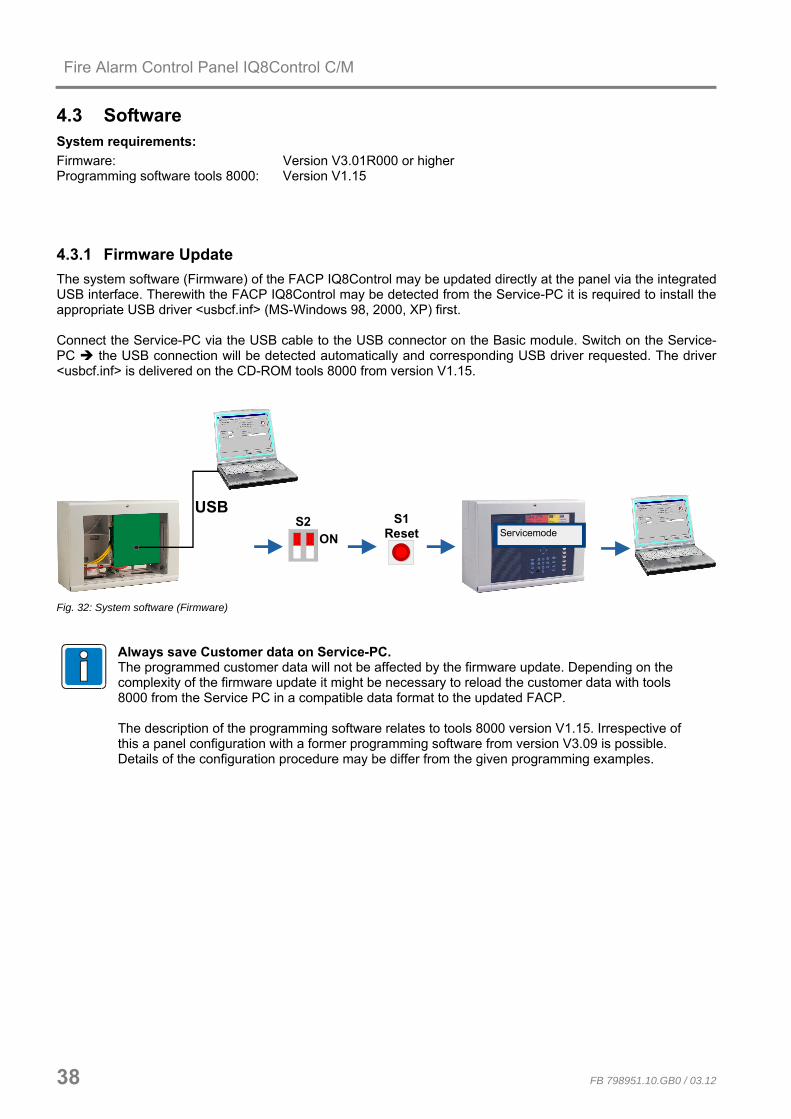
4.3 Software System requirements: Firmware: Version V3.01R000 or higher Programming software tools 8000: Version V1.15
4.3.1 Firmware Update The system software (Firmware) of the FACP IQ8Control may be updated directly at the panel via the integrated USB interface. Therewith the FACP IQ8Control may be detected from the Service-PC it is required to install the appropriate USB driver <usbcf.inf> (MS-Windows 98, 2000, XP) first. Connect the Service-PC via the USB cable to the USB connector on the Basic module. Switch on the Service-PC the USB connection will be detected automatically and corresponding USB driver requested. The driver <usbcf.inf> is delivered on the CD-ROM tools 8000 from version V1.15.
S1Reset
S2ON Servicemode
USB
Fig. 32: System software (Firmware)
Always save Customer data on Service-PC. The programmed customer data will not be affected by the firmware update. Depending on the complexity of the firmware update it might be necessary to reload the customer data with tools 8000 from the Service PC in a compatible data format to the updated FACP. The description of the programming software relates to tools 8000 version V1.15. Irrespective of this a panel configuration with a former programming software from version V3.09 is possible. Details of the configuration procedure may be differ from the given programming examples.

Fire Alarm Control Panel IQ8Control C/M
FB 798951.10.GB0 / 03.12 39
1. Open panel housing
2. Set DIL switch S2 (1+2) on the Basic module in Pos. ON (LED V50 lits).
3. Press reset button FACP reset
4. Wait until FACP is resetted and the display message „Servicemode“ appears.
5. Connect USB cable (Part No. 789863) to the USB-connector of the FACP IQ8Control an.
6. Start tools 8000 software on the Service PC and select >Tools / actualize panel software<.
7. After the firmware update the message >Update successful< appears on the Service-PC
8. Remove USB-plug from the Basic module and set DIL-switch in position OFF the FACP IQ8Control will be automatically resetted and returns to the normal operation mode.

Fire Alarm Control Panel IQ8Control C/M
40 FB 798951.10.GB0 / 03.12
4.3.2 Customer data programming The Fieldbus- und panel interface PLus (Part No. 789862.10) or panel interface RS232 (Part No. 769828) incl. accessories is required to configure the panels Customer data. The software tools 8000 from Version V1.15 provides the configuration of the FACP IQ8Control functions and customizing the system to all requirements. A detailed guideline to the configuration of the FACP IQ8Control is given in the Online-Help file in tools 8000.
4.3.2.1 Fieldbus- und panel interface PLus (Part No. 789862.10), USB Therewith the interface may be detected from the Service-PC it is required to install the appropriate USB driver >usbefi.inf< (MS-Windows 98, 2000, XP). Connect Service-PC and the interface with the USB-cable. Switch ON the Service-PC the USB connection will be detected automatically and corresponding USB driver requested. The USB-driver >usbcf.inf< is delivered on the CD-ROM with the programming software tools 8000 from version V1.15.
tools 8000
USB
Fig. 33: Fieldbus- und panel interface PLus (Part No. 789862.10), USB
4.3.2.2 Panel interface RS232 (Part No. 769828), serial
tools 8000seriellserial
Fig. 34: Panel interface RS232 (Part No. 769828), serial
For safety, always save your data on the hard disk of the service PC. The saved customer data can then be transferred quickly and easily from the service PC to the FACP IQ8Control.

Fire Alarm Control Panel IQ8Control C/M
FB 798951.10.GB0 / 03.12 41
4.3.3 Housing contact
X7 X88765
Hou
sing
con
tact
V2
Housingopen
1234
Depending on the panel housing used, up to four cover contacts can be connected to the connection terminals of the Basic module. A single contact per housing is integrated by factory settings. The opened housing contact is indicated by the illuminated LED V2.
5 6
7 8
4 3
2 1
4 3
2
1
5 6
7 8
set jumper
4
3 2
1
5 6
7 8
setjumper
4 3
2 1
5 6
7 8
Connection of one housing contact Connection of two housing contacts Connection of three housing contacts Connection of four housing contacts
Fig. 35: Housing contact
The cover contact must be opened when the service PC is connected, otherwise connection of the PC is not recognised by the central unit.

Fire Alarm Control Panel IQ8Control C/M
42 FB 798951.10.GB0 / 03.12
4.3.4 Serial interface The serial interface on the Basic module may be configured as a TTY interface (20 mA) or as an RS485 interface.
The required interface to connect external devices is selected by the Service software tools 8000 from Version V1.15.
TTY interface
A B ARxD TxD
B
external devices
Rx +Rx -Tx +Tx -
trans
mitt
rece
ive
TTY
rece
ive
trans
mitt
V62 V63
TxDreversedPolarity
These four terminals may be used for connecting an external device, e.g. a protocol printer or the kit for a redundant transmission path (Part No. 784749*), via the TTY interface (20 mA). The cable length between external device and interface must not exceed 1000 m.
In operation (green LED)
If wired correctly, the green LED (TxD) will blink at the transmission frequency to provide visual indication of proper interface wiring.
Reverse polarity indicator (red LED)
If the connection cables are transposed at the terminals, red LED (Reversed polarity) will light up.
* This option may be installed inside the FACP housing with the Top-hat rail mounting kit (Part No. 788652) – refer to Chapter Options -.
Fig. 36: TTY interface

Fire Alarm Control Panel IQ8Control C/M
FB 798951.10.GB0 / 03.12 43
RS485 interface
An external device, such as an LCD display panel, can be connected to the A/B terminals via the RS485 interface.
A B
RS4851
external device
BA+-
+UBe
xt.
GN
D
X33123
123
X35
A B
RS4852
X34X32123
123
• The RS485 BUS must be connected with an EOL resistor at both ends of the loop.
• If the FACP incl. basic module is the last device on a loop end, the integrated EOL resistor can be activated with the X32 jumper.
Fig. 37: RS485 interface
RS 485-1
A/B Connection of the interface cable – total length max. 1000 m
X32 closed RS 485 termination resistance activated
open RS 485 termination not activated
RS 485-2
A/B
X33/35
X34
Do not alter position of the jumpers!
Do not connect terminals!

Fire Alarm Control Panel IQ8Control C/M
44 FB 798951.10.GB0 / 03.12
Common trouble relay
CNCNO
SaS-Relay
exteral device
FAULT
Contact : change-over (EMI protected) Breaking capacity : 30 V DC / 1A Function : Common trouble (SaS-relay FAULT) If the control panel detects at least one trouble incident, relay activation will be interrupted and the relay will change its control status.
Normally energized mode of the relay contact
The relay is activated when the Fire Alarm Control Panel is in the normal mode. This application provides a fault message even in the emergency operation of the panel. In case of a total power loss, a fault message can be transmitted via the dry relay contact.
Fig. 38: Common trouble relay
Do not connect relays (AE) of the FACP with alternating voltage. Even in the case of a >dry relay contact< it is not possible to switch an external AC-voltage.
Inputs IN1 and IN2
GND
e. g. external power supply
1 2IN
Monitored inputs IN1 and IN2 allow you to monitor two external devices, such as an external power supply for feeding the control panel components. An external contact is required for activating an input and will be open in the normal mode. This contact is used to switch input IN1 or IN2 to GND in order to send a trouble message to the Fire Alarm Control Panel. For each input, Programming software may be used for entering specific additional text of 25 characters in length that will be shown on the display and protocol printer in the event of an incident.
Fig. 39: Inputs IN1 and IN2

Fire Alarm Control Panel IQ8Control C/M
FB 798951.10.GB0 / 03.12 45
4.3.5 Micro module slot Eight connection terminals are provided at the micro module slot on the Basic module for connecting the freely selectable micro module. Assignment of the eight screw terminals will depend on the micro module type used.
X2
X1
X27X28X29X30
F1
mic
ro m
odul
e
X3
micro module1 2 3 4 5 6 7 8
X11
- A
X12
- B
Fig. 40: Micro module slot, connection terminals and Location of Jumpers
All jumpers in horizontal position
X27 X28 X29 X30
Required configuration for all micro modules apart from essernet® (factory setting) EMC protection for this micro module connection terminal is activated
All jumpers in vertical position
X27 X28 X29 X30
Only required for essernet® micro module. The EMC protection is activated on the micro module for essernet® and therefore switched off on the basic module.
The micro module must be configured with the appropriate jumper and DIL-switches and additionally programmed in the panels customer data.

Fire Alarm Control Panel IQ8Control C/M
46 FB 798951.10.GB0 / 03.12
4.3.6 Technical data Basic module
Operating voltage : Internal via the power supply module, +5 V DC / + 12 V DC
Quiescent current : approx 215 mA @ 12 V DC without operating module approx 230 mA @ 12 V DC incl. operating module approx 295 mA @ 12 V DC incl. operating module ¼ VGA
Emergency mode operation : available
Fuses : F1 = T1,25 A H/230 V AC
F2 = T2,5 A
F3 = T2,5 A
F4 = T2 A / 12 V DC
mains voltage, primary
battery 1
battery 2
supply voltage for external devices
Supply voltage for external devices : max. 12 V DC/ 2 A (terminal +Ubext / GND)
Common fault relay : 1 dry change-over contact Contact rating max. 30 V DC / 1A Relay operation with common fault programmable in the customer data
Terminals
- Mains connection
- Communication cables
:
:
1,5 mm2 up to max. 2,5 mm2
removable, max. 1,5mm2
TTY -interface or RS485-1 interface
: :
20 mA, max. 1000 m cable length max. 1000 m cable length
Do not connect relays (AE) of the FACP with alternating voltage. Even in the case of a >dry relay contact< it is not possible to switch an external AC-voltage.
Compatibility : Part No. 772481 Basic module IQ8Control C Part No. 772482 Basic module IQ8Control M
The Basic module is suited for the Fire Alarm Control Panels IQ8Control C/M with the required power supply module (Part No. 802426 from index G).
The required loop voltage (27,5 V or 42 V for esserbus® PLus) must be selected on the power supply module.
For the Fire Alarm Control Panel system 8000 the basic module may be used as replacement device. This requires the power supply module (Part No. 802426 from index G).

Fire Alarm Control Panel IQ8Control C/M
FB 798951.10.GB0 / 03.12 47
4.4 Field device module The Field device module required in order to configure a stand-alone FACP in accordance to the appropriate standards and guidelines. The Field device module integrates all of the input and output modules that are necessary in addition to the modules on the Basic module to operate as a Fire Alarm Control Panel to DIN VDE 0833. This are e.g. terminals to connect a Fire department notifying system, a master box and programmable relays.
There are two different kinds of Field device module available for the FACP IQ8Control:
1) Part No.772477 - Field device module with one micro module slot
2) Part No.772479 - Field device module without micro module slot
The FACP must not be operated with series 01 Field device modules.
Features
• Terminals for a Fire Department Notifying System (8 Inputs / 8 Outputs)
• Terminals for a Master box (manned centre link) incl. relay to switch the required supply voltage and monitored input to indicate the triggered master box.
• Three freely programmable relays – alternatively - monitored und positive switching, - positive switching - or dry change-over contact
• Emergency operation for all four relays available
Do not use the relays for the monitored activation of alarm devices. Monitoring of the relays is only used to detect interruptions and short circuits. If a control panel is required to function in accordance with DIN 0833, you should program the relays with the >common fire< (K2), >common alarm< (K3) and >common disconnection< (K4) in the customer data of the control panel. In the emergency mode the relays will be triggered with the assigned function. If several Fire Alarm Control Panels are connected together in the essernet®, the master box can be connected to one of the other FACPs.
Do not connect relays (AE) of the FACP IQ8Control with alternating voltage. Even in the case of a >potential free relay< mode it is not possible to switch an external AC-voltage.

Fire Alarm Control Panel IQ8Control C/M
48 FB 798951.10.GB0 / 03.12
Field device module (Part No.772479) without micro module slot
123
X4X5X6X7X8F1F2 F3F4
BR
19B
R18
BR
17
BR
15B
R14
BR
13
BR
11B
R10
BR
9
BR
8B
R 7
BR
6
BR
5B
R 4
BR
3
GR1
+-
K4
BACK
2A
BR1
BR
21
BR2V20V21 V22
V8V10V41V42
K1
K3 K2 K1
GND
2A 2A 1A
BR
12
BR
16
BR
20
K3K4 K2
123
123
123
123
123
Field device module
CNCNO CNCNO CNCNO CNCNO
Fig. 41:Field device module (Part No.772479)
Field device module (Part No.772477) with micro module slot
123
X4X5X6X7X8X9F1F2 F3F4
BR
19B
R18
BR
17
BR
15B
R14
BR
13
BR
11B
R10
BR
9
BR
8B
R 7
BR
6
BR
5B
R 4
BR
3
GR1
+-
K4
BACK
2A
BR1
BR
21
BR2V20V21 V22
V8V10V41V42
K1
K3 K2 K1
GND
2A 2A 1A
BR
12
BR
16
BR
20
K3K4 K2
123
123
123
123
123
Field device module
CNCNO CNCNO CNCNO CNCNO
X10
MM2
18
Fig. 42: Field device module (Part No.772477)
The Field device module (if available) must always be placed on the >System connector 1< of the Basic module.

Fire Alarm Control Panel IQ8Control C/M
FB 798951.10.GB0 / 03.12 49
Relay K1 Relay for connecting a master box. May also be used as a freely programmable relay.
Selection of operating mode and emergency function by means of jumpers. (Monitoring range 50 Ω to 1 kΩ)
Contact rating when used as a >non-monitored change-over contact< < 30 V DC/ max.1 A
Relay K2,3,4 Relay with common function. May also be used as a freely programmable relay. Selection of operating mode and emergency function by means of jumpers.
Contact rating when used as a >non-monitored change-over contact< < 30 V DC/ max. 2 A
8 inputs for connecting a fire department operating panel – top – IN 1-8 X4
8 outputs for connecting a fire department operating panel – bottom – OUT 1-8
X5 Connection terminals for (master box relay, K1)
for connecting the master box supply voltage, incl. confirmation input for verifying master box activation
X6 Connection terminal for relay K2
X7 Connection terminal for relay K3
X8 Connection terminal for relay K4
GR1 = Internal primary loop input (primary line no. XX24, XX= FACP no.)
Normal operation R = 10 kΩ
Fire alarm R ≤ 5 kΩ
Trouble R = 1 kΩ
X9 / X10 Terminals for the micro module slot (only Field device module Part No. 772477)
F1
F2 to F4
T1A – Fuse for Relay K1
T2A – Fuse for Relay K2, K3, K4
V8, V10, V11, V12
The LED lights while the corresponding relay is activated or when is has been programmed for inverse control in the customer data programming
V20 to V22 yellow LED V 20 will light up when the Fire Alarm Control Panel is operating in CPU failure mode
green LED V 21 will light up when the cover contact (control panel housing) is open
red LED V 22 will light up if a fire alarm is detected while the control panel is operating in CPU failure mode
BR1 and BR2 Solder bridges for setting the master box control in emergency operation
BR3 to BR5 Jumpers for setting the CPU failure mode function for relays K2, K3, K4
BR6 to BR20 Jumper to select the operation mode of relay K1 and relays K2, K3, K4
BR21 Coding jumpers for fire department operating panel with >fire control off / revision< function (Terminals X4/IN8)
Jumper in position 2-3 >fire control off / revision< not active / off (factory setting)
Jumper in position 1-2 >fire control off / revision< active / on
Do not connect relays (AE) of the FACP IQ8Control with alternating voltage. Even in the case of a >potential free relay< mode it is not possible to switch an external AC-voltage.

Fire Alarm Control Panel IQ8Control C/M
50 FB 798951.10.GB0 / 03.12
Connection terminals
Screw terminal: removable, Connection terminals max. 1.5mm2
removable
removable
X4
IN - top
OUT - bottom
Fig.43: Connection terminals Connection terminals fire department operating panel
Connection of the micro module
Eight connecting terminals are provided for the micro module slot of the Field device module. The actual connection of the eight terminals depends on the type of module used.
If an essernet® micro module is used, this module may only be inserted into the micro module slot of the basis module. The essernet® micro module requires adaptation of the terminal card on the basis module. The EMI protection must be implemented by external EMI-protection devices.
Primary loop input Pri+/Pri-
Monitored primary loop input Pri+/Pri- (terminal X8) has the purpose of monitoring CPU failure in the essernet®
Network. These terminals are used, for example, to connect the common fire relay of another Fire Alarm Control Panel. In the event of trouble in the essernet® micro module, a fire alarm signal may still be sent via the relay contact to the primary loop input of this control panel. The display at this Fire Alarm Control Panel will then show the message >Prim. loop fire< in the event of an incident occurring. The primary loop input can be switched off or on and reset via the corresponding primary loop number.
GR1
10KR*
R* = monitored end-of-line resistor R =10 kΩ
R= 10 kΩ Normal status R= 5 kΩ Fire alarm, display >Prim. loop fire< R= 1 kΩ Trouble Primary loop no.: xx24 (xx = Panel no. 01-31)
Fig. 44: Primary loop input Pri+/Pri-

Fire Alarm Control Panel IQ8Control C/M
FB 798951.10.GB0 / 03.12 51
4.4.1 Connecting a fire department operating panel
X4
bottom - terminals
top - terminals
• Wiring differs from area to area and is governed by the requirements of the regional fire department.
• A 12 V DC voltage is required for operation.
IN1
IN8
IN2
IN3
IN4
IN5
IN6
IN7
X4
FD call LED on (IN1 on GND)(closer)
MB disconnected
acoustic signals offcheck MB
reset FACPfire control off / revision
do not use
topterminals
do not use
If the terminal IN8 (fire control off / revision) is not used, jumper BR21 must always be fitted at position 2-3 ! Current load per output (OUT1 to OUT 8) max. 25 mA.
OUT1
OUT8
OUT2
OUT3
OUT4
OUT5
OUT6
OUT7
X4
MB activatedextinguishing system activatedcommon fire
MB disconnected
MB activation prevent
do not use
acoustic signals off
fire control off (revision)
bottomterminals
Fig. 45: Connection terminals fire department operating panel

Fire Alarm Control Panel IQ8Control C/M
52 FB 798951.10.GB0 / 03.12
4.4.2 Connecting the master box (Relay K1) Relay K1 for the connection of a master box is part of the peripheral module. The control configuration of relay K1 can be set to
• monitored and switching the positive potential
• switching the positive potential
• or as a non-monitored change-over contact
by means of jumpers.
BR
8B
R 7
BR
6
BACK
BR1BR2
K1
CNCNO
K1
GND
123
Fig. 46: Location of the master box relay K1 and the jumpers BR 6 to 8 on the Field device module
Setting the operating mode for relay K1
Jumpers Function
BR 1
Activation of master box relay (K1) also in the event of a fire alarm with the control panel in the CPU failure mode (factory setting)
BR 1
No activation of the master box in the event of CPU failure-fire
BR 2
No activation of the master box in the event of a fire alarm when the cover contact on the control panel housing is open (factory setting)
BR 2
Activation of master box even with cover contact open (outer housing)

Fire Alarm Control Panel IQ8Control C/M
FB 798951.10.GB0 / 03.12 53
Operating mode 1 Relay K1 positive switching and monitored
680
R * S*
CNCNO BAC
K
GN
DK1
+12V
DC
Ub
int.
K1
+mon
itorin
g
Pan
el in
tern
al
V*
Fig. 47: Terminal of the master box relay K1
BR8 BR7 BR6
1
2
3
1
2
3
1
2
3
Relay K1
positive switching (+12 V DCintern / max. 1 A) and monitored
R* Monitored end-of-line resistor R = 680 Ω (factory setting) Monitoring capability of internal resistor in master box 50 to 1000 Ω (refer to customer data programming)
S* Dry confirmation contact in master box
Diode V* From Hardware index B the diode V* is integrated in the Field device module.

Fire Alarm Control Panel IQ8Control C/M
54 FB 798951.10.GB0 / 03.12
Wiring example:
Operating mode 1 Relay K1 – positive switching and monitored
680Ω
S*
R*
+UB
BACK
ÜE -
ÜE +
+ UB ext.+UB
10 9 8 7
NO
C
GND
Relaycommon fire
RelayMFAB activated
Master box(schematic circuit diagram)
FACP IQ8Control C/M Field device module
alarm
acknowledgeMFAB
acknowledge
fire dept. key box
Fig. 48: Schematic circuit diagram master box with FDKB adapter

Fire Alarm Control Panel IQ8Control C/M
FB 798951.10.GB0 / 03.12 55
Operating mode 2 Relay K1 positive switching, not monitored
+12V
DC
Ub
int.
K1
CNCNO BAC
K
GN
DK1
BR8 BR7 BR6
1
2
3
1
2
3
1
2
3
Relay K1
Positive switching (+12 V DCintern / max. 1 A), not monitored
Fig. 49: Terminal of the master box relay K1
Operating mode 3 Relay K1 not monitored change-over contact
K1
BAC
K
GN
DK1CNCNO
BR8 BR7 BR6
1
2
3
1
2
3
1
2
3
Relay K1
Potential-free, not monitored change over contact
External voltage < 30 V DC, max. 1 A
Fig. 50: Terminal of the master box relay K1
The IQ8Control FACP's relays may only be connected to DC voltages. No AC voltage may be applied, not even when a relay is programmed as a >non-monitored change-over contact<.

Fire Alarm Control Panel IQ8Control C/M
56 FB 798951.10.GB0 / 03.12
4.4.3 Connecting the Relays K2, K3, K4 Location of the relay K2,K3,K4 and the jumpers BR9 to 20 on the Field device module
BR
19B
R18
BR
17
BR
15B
R14
BR
13
BR
11B
R10
BR
9
K4 K3 K2
BR
12
BR
16
BR
20
K3K4 K2
123
123
123
CNCNO CNCNO CNCNO
Jumpers are used for adjusting the three relays K2, K3 and K4 to a variety of requirements. The three relays may be coded independently of each other as >positive-switching< and >monitored, positive-switching< or as >potential-free change-over contact<.
Fig.51: Connecting the Relays K2,K3,K4
Relay K2 K3 K4 Positive switching / monitored
CNCNO
+
K
10 KR *
n. c.
+12V DC Ub int.
UMess
Signale in operation
+ -
monitoring
BR 9BR 10BR 11
1
2
3BR 12
1
2
3
1
2
3
1
2
3
BR 13BR 14BR 15BR 16
1
2
3
1
2
3
1
2
3
1
2
3
BR 17BR 18BR 19BR 20
1
2
3
1
2
3
1
2
3
1
2
3
Positive switching / not monitored
+12V DCUb int.
K
+ -
n. c.
CNCNO
BR 9BR 10BR 11BR 12
1
2
3
1
2
3
1
2
3
1
2
3
BR 13BR 14BR 15BR 16
1
2
3
1
2
3
1
2
3
1
2
3
BR 17BR 18BR 19BR 20
1
2
3
1
2
3
1
2
3
1
2
3
Change-over contact / not monitored
K
CNCNO
BR 9BR 10BR 11BR 12
1
2
3
1
2
3
1
2
3
1
2
3
BR 13BR 14BR 15BR 16
1
2
3
1
2
3
1
2
3
1
2
3
BR 17BR 18BR 19BR 20
1
2
3
1
2
3
1
2
3
1
2
3

Fire Alarm Control Panel IQ8Control C/M
FB 798951.10.GB0 / 03.12 57
CPU failure mode function of relays K2, K3 and K4
123
BR
5B
R 4
BR
3
K3K4 K2
Fig.52: Location of the emergency mode jumpers BR3 to 5 on the Field device module
K2 K3 K4
BR
4
1
2
3
BR
3
1
2
3
BR
5
1
2
3
Jumper X in position 1/2 No activation of the relay while the Fire Alarm Control Panel is in CPU failure mode (state on leaving factory).
BR
4
1
2
3
BR
3
1
2
3
BR
5
1
2
3
Jumper X in position 2/3
Relay also activated while the Fire Alarm Control Panel is in CPU failure mode.
Used if a common function is programmed for the relays, such as >common fire<, >common alarm< and >common disconnection<.

Fire Alarm Control Panel IQ8Control C/M
58 FB 798951.10.GB0 / 03.12
4.4.4 Technical data Field device module
Operating voltage : Internal via the power supply module, +5 V DC / + 12V DC
Quiescent current : approx. 15 mA @ 12 V DC
Fuse F1 Fuse F2, F3, F4
: :
T1A – slow blow (relay K1) T2A - slow blow (relays K2 to K4)
terminals : Max. 1,5 mm2, removable
Relay K1 : Relay for connecting a master box. May also be used as a freely programmable relay. Selection of operating mode and emergency function by means of jumpers.
Contact rating when used as a >non-monitored change-over contact< contact rating < 30 V DC/ max.1 A. No dry contact cause of the integrated EMI protection.
Relay K2, K3, K4 : Relay with common function. May also be used as a freely programmable relay. Selection of operating mode and emergency function by means of jumpers.
Contact rating when used as a >non-monitored change-over contact<, contact rating < 30 V DC/ max.2A No dry contact cause of the integrated EMI protection.
Fire department operating panel : 8 digital inputs
8 outputs - max. 12 V DC / 20 mA per output
Internal primary loop : monitored 10 kΩ (normal) / 5 kΩ (FIRE) / 1 kΩ (fault) Application e.g. for essernet®-emergency operation
Compatibility : Part No.772479 Field device module without micro module slot Part No.772477 Field device module with micro module slot
The IQ8Control FACP's relays may only be connected to DC voltages. No AC voltage may be applied, not even when a relay is programmed as a >non-monitored change-over contact<!

Fire Alarm Control Panel IQ8Control C/M
FB 798951.10.GB0 / 03.12 59
4.5 Extension module Depending on the module type up to three slots for micro modules are integrated on the Extension module. Connections are available for each micro module. The pin assignment of the eight screw terminals depends on the employed type of micro module. The pin assignment of the connectors is described for each micro module.
MM2
18
Extension module 772478
X3c
X2b
X1a
X 10
X11a
X12b
Fig.53: Extension module (Part No.772478) with one micro module slot
1 2 3 4 5 6 7 8 1 2 3 4 5 6 7 8 1 2 3 4 5 6 7 8
Place 1
Extension module 772476
Place 2
Place 3
V2
V1
X 22 X 23 X 24
X 6
X 5
X 4
Place 1 Place 2 Place 3
Fig.54: Extension module (Part No.772476) with three micro module slots (only IQ8Control M)

Fire Alarm Control Panel IQ8Control C/M
60 FB 798951.10.GB0 / 03.12
IQ8Control C
The Field device module with a single micro module slot (Part No. 772478) must be placed on the >System connector 1< of the Basic module. This connector is normally used by the Field device module. Without the field device module a system configuration in accordance to the standards is not possible (refer to section „Panel configuration IQ8Control C“).
IQ8Control M
Up to two connectors are available for Extension modules (Field device and or Extension module). Normally the lower >connector 2< is used to connect an Extension module. If required the upper >connector 1< may be used too for an Extension module. In this case the integration of an Field device module is impossible. In this case mounting of the field device is not possible anymore (refer to section „Panel configuration IQ8Control C“).
Extension module with a single micro module slot (Part No. 772478)
This Extension module must be configured in the panels data programming as a Field device module.
X 1a/2b/3c connector >System connector 1 or 2< of the Basic modules Refer to note!
X11a/12b Connector for a micro module (Do not connect an essernet® micro module)
X 10 Terminals for the micro module wiring (refer to the I-text at the bottom)
Extension module with three micro module slots (Part No.772476)
Only FACP IQ8Control M configurable. LED V1 ON – Common fire alarm
LED V2 ON – CPU failure
place 1 Micro module slot only for micro module
place 2 Micro module slot only for micro module
place 3 Micro module slot only for micro module
Do not connect an essernet® micro module, Refer to note!
X22 terminal for micro module slot 1
X23 terminal for micro module slot 2
X24 terminal for micro module slot 3
X 4/5/6 Plug contact of >System connector 1 or 2< of the Basic module Refer to note!
If an essernet® micro module is installed, this module can only be operated on the micro module slot of the Basic module.
4.5.1 Technical Data Extension module
Operating voltage : Internal via the power supply module, +5 V DC
Quiescent current : approx. 10 mA
Terminals : max. 1,5 mm2, removable
Compatibility : Part No.772478 Extension module with one micro module slot Part No.772476 Extension module with three micro module slots

798951.10.GB0 G 299044
03.2012 G 205129 Technical changes reserved! © 2012 Honeywell International Inc.
GB
Installation Instruction
Fire Alarm Control Panel IQ8Control C/M Micro modules

Fire Alarm Control Panel IQ8Control C/M
62 FB 798951.10.GB0 / 03.12
5 Micro module The FACP IQ8Control C / M has a modular design, so that micro modules can be replaced/extended at any time.
Only remove or insert micro modules when the FACP is voltage free. • Switch off the power and battery supply. • Wait at least 10 seconds before the micro modules are replaced or supplemented. • Take suitable measures to discharge static electricity. • Check correct installation (micro modules and connection cables). • Switch on the power and battery supply. • If necessary, check/supplement the customer data using the programming software tools
8000. 5.1 Loop modules The following two loop modules are available for the Fire Alarm Control Panel IQ8Control C/M: esserbus® loop module (Part No.784382 / 784382.10 / 784382.D0) To connect fire detectors series 9200 and FACP esserbus® transponders. For the loop module operation the power supply module (Part No.802426) must be configured with the appropriate jumper to 27,5V loop voltage. esserbus® PLus loop module (Part No.804382 / 804382.10 / 804382.D0) Fire Alarm Control Panels IQ8Control C/M with esserbus® PLus are based on the standard esserbus® functionality with the additional function to connect and power audible alarm devices directly to the loop. For this operation of the loop module it is necessary to set the loop voltage of the Power supply module (Part No.802426) with the appropriate jumper to 42 V. The audible alarm devices connected to esserbus® PLus are supplied by the loop voltage and do not need an external power supply. Basic data on loop of esserbus® and esserbus® PLus • Less than 127 loop devices or 127 zone isolators per loop • Loop may be divided into 127 individual detector zones (customer data programming) • No more than 32 fire detectors per detector zone • Capability of combining loop and spur loop operation. No sub-spur branching! • Recommended type of cable for loop:
Use clearly identified communications cable I-Y (St) Y n x 2 x 0.8 mm or fire alarm cable! • Max. impedance of the loop incl. spur measured with respect to the load factor for IQ8Quad detectors: max.
3500 m1). For cable diameter with 0,8 mm and a max. Loop resistance of 130 Ω (measured from terminal A+ to B+).
• Max. 8 communications transponder per loop max. 16 communications transponder per FACP
• max. 8 Smoke aspirating systems LRS compact/eb or LaserFocus per loop max. 16 Smoke aspirating systems LRS compact, LRS compact/eb, LRS compact/net or LaserFocus per FACP
• max. 25 Smoke aspirating systems LRS 100 or LRS-S 700 per loop, max. 50 per FACP (System software from Version V3.01 required).
• max. 32 esserbus® transponders per loop max. 100 esserbus® transponders per FACP OR
• max. 32 Smoke aspirating systems TITANUS PRO / TOP SENS® EB per loop. max. 100 Smoke aspirating systems per FACP.
1) refer table chapter 5.1.3.
Damage to the system! It is only possible to operate the esserbus® PLus devices compatible with the higher loop voltage (42 V DC). Mixed operation of Standard and esserbus® PLus function within one panel is not possible ! Loop devices compatible with esserbus® PLus (transponders, detectors MCP´s etc.) are identified by the Part No. 80xxxx.
These 80xxxx devices are also fully compatible to the existing devices with Part No. 78xxxx and may be used in standard esserbus® installations.

Fire Alarm Control Panel IQ8Control C/M
FB 798951.10.GB0 / 03.12 63
Mode of loop operation
The esserbus® /esserbus® PLus is a monitored two-wire loop fed from two sides and exhibiting loop topology. The use of zone isolators allows you to combine ring and spur loops as well as divide the loop into 127 detector zones with a total of 127 loop devices. All esserbus® loop devices remain functional in the event of interruption (break in wire) in the loop. If a short circuit occurs, only the faulty element between two zone isolators will be disconnected. Even during this malfunction all other loop devices remain operational. On the esserbus® it is possible to group special fire detectors and manual call points or manual release devices in separate detector zones. You may also simultaneously operate esserbus® transponders in separate detector zones on the loop. The esserbus® transponders are decentralised input/output modules capable of being installed as loop devices on the esserbus®. Commissioning a wired and functional loop requires use of the service PC and the software tools 8000 This Service software initiates an automatic wiring recognition function on the loop and addresses all esserbus® loop devices automatically. There is no longer any need to set addresses manually. For further information on programming, please refer the online help for the programming software tools 8000. To indicate a data communication between FACP and detectors the corresponding LED on the basic module flashes. The green LED of the IQ8Quad fire detector flashes each 30 seconds.
Operation of zone isolators
A short circuit on the loop will cause the cut-off relays to open in the relevant zone isolator and disconnect the faulty segment (e.g., a detector zone) from the loop. The disconnected detectors will be shown on the display with trouble message Com.trbl (communication trouble). All other loop devices on the loop, as well as the fire detectors or esserbus® transponders whose zone isolator has triggered, will remain operational. The zone isolators do not work on an open circuit, e.g. break in wire. Bi-directional ring interrogation keeps all loop devices on the loop functional. All Fire detectors series IQ8Quad provides an integrated loop isolator. For additional loop devices optional isolators are available.
Use of zone isolators
1. Always upstream of the point where the loop crosses into another fire compartment
2. On changing from special fire detectors to manual call points (and vice versa)
3. At least in the 32nd fire detector of a detector zone
§
With the newly developed battery monitor modules, the IQ8Control FACP now satisfies the expanded requirements of EN 54-4/A2, as well as the amended requirements for the display and operating concept according to EN 54-2. (For CPD approval number, see Chapter 1.1) In accordance with the VdS device approval of the IQ8Control FACP, the emergency operation fire function now replaces a redundant CPU in accordance with VDE 0833-2 for systems with more than 512 detectors or a monitoring area up to 48,000 m². This integrated emergency redundancy also allows further processing of an alarm in the essernet® in event of the failure of a central processor without the need for additional hardware or software.

Fire Alarm Control Panel IQ8Control C/M
64 FB 798951.10.GB0 / 03.12
5.1.1 esserbus® loop module (Part No. 784382 / 784382.10 / 784382.D0) The loop module enables you to connect the loop - the esserbus® and is configured with Programming software tools 8000 from index V1.15.
esserbus®
Fire alarm and extinguishing computer 8010
Fig. 55: esserbus®
K2 (B)
K1 (A)
LED 2
LED 3
LED 4LED 1
Loop module
X1
Fig. 56: Loop module (Part No. 784382 / 784382.10 / 784382.D0)
• Connect cable shielding of the loop only at one side. • When using the module in door control systems, place the enclosed labels on or in the FACP
housing (see chapter 11.1). X 1 64-way plug connector to micro module slot of the Basic module, Field device module or
Extension module K1, K2 Bi-directional loop interrogation by loop isolators
(K1 = A+, A- / K2 = B+, B-) LED 1 (SMD) red, flashing in normal mode in time with communication on the loop
(SMD) red, lit Short circuit on loop LED 2 (SMD) yellow, lit Module faulty LED 3 (SMD) red, flashing + 24 V supply voltage failure or communication to
control panel processor interrupted (SMD) red, lit Module in CPU failure mode (control panel CPU failure)
LED 4 (SMD) yellow, flashing Processor program running – normal mode (SMD) yellow, flashing rapidly Module in test mode

Fire Alarm Control Panel IQ8Control C/M
FB 798951.10.GB0 / 03.12 65
5.1.2 esserbus®-PLus loop module (Part No. 804382 / 804382.10 / 804382.D0) This module provides the "esserbus® PLus" loop mode, e.g. for direct connection of audible loop devices. Note that the esserbus® PLus operation requires special components and panel settings. Observe load factor refer table chapter 5.1.3.
Mixed operation of Standard and esserbus® PLus function is not possible!
esserbus®-PLus
Fire alarm and extinguishing computer 8010
Fig. 57: esserbus®-PLus
• Connect cable shielding of the loop only at one side. • When using the module in door control systems, place the enclosed labels on or in the FACP
housing (see chapter 11.1).
removable
X2K2 K1
LED5
LED2
LED3LED1
LED4 B-
B+
A-
A+
Released cable terminal: Press in upper tab and fit cable below.
Fig. 58: Loop module (Part No. 804382 / 804382.10 / 804382.D0)
X 1/2 64-way plug connector to micro module slot of the Basic module, Field device module or Extension module
K1,K 2 Bi-directional loop interrogation by loop isolators (K1 = A+, A- / K2 = B+, B-)
LED 1 (SMD) red, flashing +42V supply voltage failure or communication to control panel processor interrupted (SMD) red, lit Module in CPU failure mode (control panel CPU failure)
LED 2 (SMD) yellow, flashing Processor program running – normal mode (SMD) yellow, flashing rapidly Module in test mode
LED 3 (SMD) red, lit esserbus® PLus Mode activated +42 V loop voltage
LED 4 (SMD) yellow, flashing Module reset (SMD) yellow, lit Module defect
LED 5 (SMD) red, flashing in normal mode in time with communication on the loop (SMD) red, lit Short circuit on loop
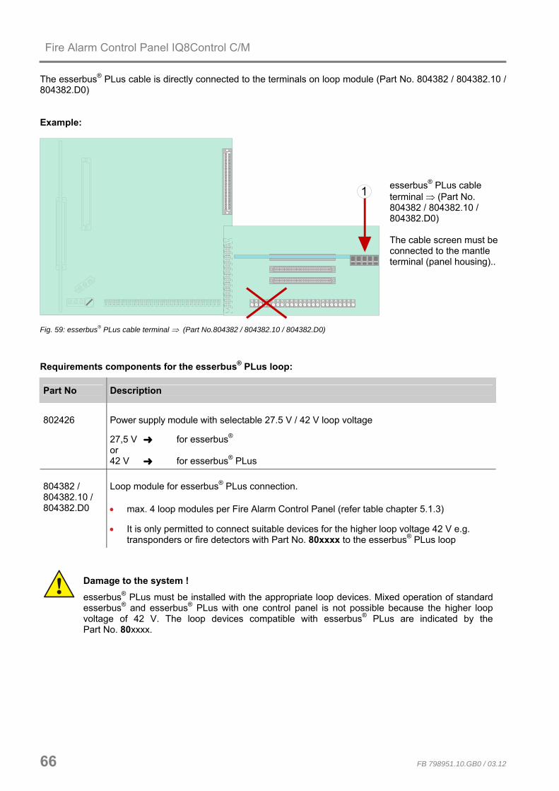
Fire Alarm Control Panel IQ8Control C/M
66 FB 798951.10.GB0 / 03.12
The esserbus® PLus cable is directly connected to the terminals on loop module (Part No. 804382 / 804382.10 / 804382.D0) Example:
1 esserbus® PLus cable terminal ⇒ (Part No. 804382 / 804382.10 / 804382.D0) The cable screen must be connected to the mantle terminal (panel housing)..
Fig. 59: esserbus® PLus cable terminal ⇒ (Part No.804382 / 804382.10 / 804382.D0)
Requirements components for the esserbus® PLus loop:
Part No Description
802426 Power supply module with selectable 27.5 V / 42 V loop voltage
27,5 V for esserbus® or 42 V for esserbus® PLus
804382 / 804382.10 / 804382.D0
Loop module for esserbus® PLus connection.
• max. 4 loop modules per Fire Alarm Control Panel (refer table chapter 5.1.3)
• It is only permitted to connect suitable devices for the higher loop voltage 42 V e.g. transponders or fire detectors with Part No. 80xxxx to the esserbus® PLus loop
Damage to the system !
esserbus® PLus must be installed with the appropriate loop devices. Mixed operation of standard esserbus® and esserbus® PLus with one control panel is not possible because the higher loop voltage of 42 V. The loop devices compatible with esserbus® PLus are indicated by thePart No. 80xxxx.

Fire Alarm Control Panel IQ8Control C/M
FB 798951.10.GB0 / 03.12 67
5.1.2.1 esserbus® PLus alarm devices Available loop alarm devices for directly connection to the esserbus® PLus loop. Part No. Name Load factor (LF) Fire detector IQ8Quad 802383 Visual 802384 Audible
2
802385, 802385.SVxx Visual + audible + speech 802386, 802386.SVxx Audible + speech
3
Alarm device IQ8Alarm 807205, 807206 Audible 807212, 807213, 807214, Visual sphere colour red or amber
white, blue or green 807224 Audible + speech 807322, 807332 Audible + visual 807372, 807372.SVxx Audible + visual + speech
3
Base sounder 806282 Audible 2
esserbus® PLus loop length Max. total load factor
≤ 700 m 96
1000 m 78
1300 m 66
1600 m 54
2000 m 48
2500 m 42
3000 m 36
3500 m (max. loop length) 30 Example: The following alarm devices are connected to a loop: 8 Fire detector IQ8Quad (Part No. 802385) with load factor 3 9 alarm devices IQ8Alarm with load factor 3
Total load factor
= Load factor 24 + = Load factor 27 ______________ = 51
Result: The total load factor obtained in this example allows for a loop length of max.1600 m (refer table).
• observe max. permitted loop length refer table chapter 5.1.2.2
• check compatibility of loop devices
• do not exceed the max. admissible total load factor of 96 (per loop)
• observe max. number of alarm devices on the loop for each individual device type
• max. total number of 127 loop devices per loop

Fire Alarm Control Panel IQ8Control C/M
68 FB 798951.10.GB0 / 03.12
5.1.2.2 Maximum line lengths based on the total load factor of a loop
FACP max. loop lenght Loop 1 Loop 2 Loop 3 Loop 4 Loop 5 Loop 6
up to 700 m 91 to 96 91 to 96 91 to 96 91 to 96 X X 800 m 85 to 90 85 to 90 85 to 90 85 to 90 X X 900 m 79 to 84 79 to 84 79 to 84 79 to 84 X X 1000 m 73 to 78 73 to 78 73 to 78 73 to 78 X X 1100 m 67 to 72 67 to 72 67 to 72 67 to 72 X X 1300 m 61 to 66 61 to 66 61 to 66 61 to 66 X X 1500 m 55 to 60 55 to 60 55 to 60 55 to 60 X X 1600 m 49 to 54 49 to 54 49 to 54 49 to 54 X X 2000 m 1 to 48 1 to 48 1 to 48 1 to 48 X X
IQ8C
ontr
ol M
up
to 4
loop
s
2100 up to 3500 m 0 0 0 0 X X up to 700 m 46 to 48 46 to 48 46 to 48 46 to 48 46 to 48 46 to 48 800 m 43 to 45 43 to 45 43 to 45 43 to 45 43 to 45 43 to 45 900 m 40 to 42 40 to 42 40 to 42 40 to 42 40 to 42 40 to 42 1000 m 37 to 39 37 to 39 37 to 39 37 to 39 37 to 39 37 to 39 1100 m 34 to 36 34 to 36 34 to 36 34 to 36 34 to 36 34 to 36 1300 m 31 to 33 31 to 33 31 to 33 31 to 33 31 to 33 31 to 33 1500 m 28 to 30 28 to 30 28 to 30 28 to 30 28 to 30 28 to 30 1600 m 25 to 27 25 to 27 25 to 27 25 to 27 25 to 27 25 to 27 2000 m 1 to 24 1 to 24 1 to 24 1 to 24 1 to 24 1 to 24
IQ8C
ontr
ol M
up
to 6
loop
s
2100 up to 3500 m 0 0 0 0 0 0
5.1.3 Technical Data loop module
Part No. 784382 / 784382.10 / 784382.D0 (esserbus®)
Part No. 804382 / 804382.10 / 804382.D0 (esserbus® PLus)
Internal voltage supply Internal +12 V and +27,5 V Internal +12 V and +42 V Quiescent current (with 127 loop devices)
60 mA @ 12 V 60 mA @ 12 V
Emergency operation yes yes Terminals removable, for max. 1,5 mm2 Recommended connecting cable
• Telephone cable I-Y (ST) Y n x 2 x 0.8mm with special designation or fire detection cable
• Loop resistance 65 Ω @ 1000 m loop length (measured from terminal A+ to B+)
• Total loop resistance max. 130 Ω (measured from terminal A+ to B+) • Up to 3500 m total loop length is possible for IQ8 fire detectors or alarm
devices with consideration of the load factor
• The permitted loop length depends on the number and type of the loop devices and may differ from the max. loop length.
• max. 2 loop modules Part No. 804382 / 804382.10 / 804382.D0 per IQ8Control C as well as max. 4 or 6 modules per IQ8Control M
• Part No. 784382 / 784382.10 / 784382.D0 loop module (esserbus®) loop module to connect Fire detectors and esserbus®-transponder. The required loop voltage 27.5 V must be selected via the jumper on the power supply module Part No. 802426 of the FACP
• Part No. 804382 / 804382.10 / 804382.D0 loop module (esserbus®-PLus) loop module to connect Fire detectors and esserbus®-transponder and alarm devices. The required loop voltage 42 V must be selected via the jumper on the power supply module (Part No. 802426) of the FACP.

Fire Alarm Control Panel IQ8Control C/M
FB 798951.10.GB0 / 03.12 69
5.2 essernet® module The essernet® module permits networking up to 31 essernet® devices, such as e.g. Fire Alarm Control Panel System 800x and IQ8Control, Intruder alarm panel system 5000 and hazard management system. Additionally optional gateways are available to connect standard devices to the network. Two essernet® micro module are available with a standard and high transmission rate.
essernet®
Hazard management system
Serial essernet®-Interface
Indicating and operating panel
Intruder alarm panel 5008
Fire alarm control panelIQ8Control M
Fire alarm control panelIQ8Control M
Fire alarm control panelIQ8Control C
Fig. 60: Example - essernet® network with different devices
Terminal card assignment
12
3
4
5
6
7
8
L1 +L1 -
L2 +
L2 -not used !
L2 +L2 -
L1 +L1 - L2 +
L2 -
L1 +L1 -
essernet® module essernet® module
not used !
not used !not used !
Fig. 61: Terminal card assignment
In a essernet® network you may only use essernet® modules with the same transmission speed. The EMI-protection / the extended EMI-protection of the LAN network must be implemented by external EMI protection devices.

Fire Alarm Control Panel IQ8Control C/M
70 FB 798951.10.GB0 / 03.12
5.2.1 essernet® micro module (Part No. 784840 / 784840.10 and 784841 / 784841.10)
The essernet® micro module must be placed on the micro module slot of the Basic module. There for it is required to set the corresponding jumpers on the Basic module to configure the terminals for the essernet® micro module. • essernet® micro module 62,5 kBd (Part No. 784840) • essernet® micro module 500 kBd (Part No. 784841)
S2 LEDessernet® module
red
yellow
green
0 1 2 3 4 5 6 7
8
90 1 2 3 4 5 6
7 8
9
X1
S1 X4 X5
Fig. 62: essernet® micro module (Part No. 784840 / 784841) or • essernet® micro module 62,5 kBd (Part No. 784840.10) • essernet® micro module 500 kBd (Part No. 784841.10)
S1
LED
essernet® module
red
yellow
green
0 1 2 3 4 5 6 7
8
9
0 1 2 3 4 5 6 7
8 9X1
S2
X4 X5
Fig. 63: essernet® micro module (Part No. 784840.10 / 784841.10)
System conformity according to EN 54-13 requires increased sensitivity in the monitoring of line connections. This has been appropriately taken into consideration in the essernet® modules (Part No. 784840.10 and 784841.10). The software of the modules remains fully compatible with earlier versions. If a new essernet® module is installed into an existing system or if an additional fire alarm control panel with an essernet® module (Part No. 784840.10 or 784841.10) is integrated into an existing network, there may be - depending on the configurations of these line connections - an increase in the number of fault messages. Common reasons for such faults include corroded connection points and loose terminal connections that were still within the tolerance ranges of the earlier versions of the essernet® modules. If you encounter such fault messages, the entire line network must be carefully inspected. Compliance with EN 54-13 requires that the greatest of care be taken when setting up such networks, which have a significant impact on the manner of line installation and the connection types.

Fire Alarm Control Panel IQ8Control C/M
FB 798951.10.GB0 / 03.12 71
S1 Rotary address switch to select panel address factor x1
S2 Rotary address switch to select panel address factor x10
X1 64 pin connector for the micro module slot inside the FACP
jumpers for configuration of the terminals IN/OUT (terminal 1+2 and 3+4) X4 / X5
X4
X4
1 2 3 4 5 6 7 8
copper cable connected
fibre optics converter
terminal card 1 2 3 4 5 6 7 8
X5
X5
fibre optic cable connected
fibre optics converter
terminal card
If data is transferred via fibre optic, two fibre optic fibre converters are always required for a data path between the devices. The documentation 798636 and 798963 contains more information about fibre optic converters.
LED Status and error indication
red on - communication error between essernet® micro module and FACP
green flashing - communication with other network devices
yellow on - communication error (A/B mode) unidirectional communication
• All other LED display combinations mean that there is a fault in the essernet® module or that measuring operation is active.
• Connect cable shielding to the appropriate terminals ! • The data signalling rate and connection cable to be used is governed by the module type
installed. In a network you may only use essernet® modules with the same data signalling rate.

Fire Alarm Control Panel IQ8Control C/M
72 FB 798951.10.GB0 / 03.12
5.2.2 Technical data essernet® micro module
essernet® micro module 62.5 k (Part No. 784840 / 784840.10)
essernet® micro module 500 k (Part No. 784841 / 784841.10)
Operating voltage : Internal via the power supply module, + 5 V DC
Internal via the power supply module, +5 V DC
Current consumption approx. 150 mA @ 12 V DC
Emergency operation : yes
Connector : A single essernet® micro module may be connected per FACP on the appropriate micro module slot on the Basic module. Observe jumper X4 / X5!
Network devices : max. 16 max. 31
Terminals : removable, for max. 1,5 mm2
Transmission speed : up to 62.5 kBd up to 500 kBd
Required cable : Telephone cable I-Y (ST) Y n x 2 x 0.8 mm, Cable length max. 1000 m.
Other cable types such as paper-wrapped cables, control lines (NYM) or smaller cross-sections are not suitable.
IBM type 1 max. 1000 m between two network devices
IBM type 2 (Earth cable) max. 1000 m between two network devices
IBM type 6 (flexible) max. 200 m between two network devices
The cable must be twisted and shielded. The signal wires are protected against interference through connection of the
cable shielding.
Transmission : Token-Passing protocol similar to DIN 19245 - 1 (Profi BUS)
Topology : loop topology (wire-breakage und short circuit tolerance)
Compatibility : essernet® micro module 62.5 kBd (Part No. 784840)
Do not operate hardware with index up to B2 with hardware from index B3 in a common panel.
Important Note! The essernet® micro modules are class A information devices (ITE) as per DIN EN 55022: 1999-05. This device may cause radio interference in a residential environment. The user may be legally obliged to take appropriate action in any case of interference. A residential area is defined as an area in which the operation of broadcast radio or television receivers must to be anticipated in a range of 10 m from the device in question In this case the operator of the system is responsible for all action needed.

Fire Alarm Control Panel IQ8Control C/M
FB 798951.10.GB0 / 03.12 73
Setting the essernet® address
The address of Network Micro Modules type 1 and 2 with hardware revision E and higher is set as a decimal number by means of two rotary switches. Use an appropriate screwdriver for setting switches S1 (x1) and S2 (x10). The actual address is represented by the total of both values.
Adressing example e.g. Panel, address 9 or 21
Schalterstellung Micro module address
S2 S1
Address factor Value Σ = S1 x 1 + S2 x 10
S1 = x 1
9 0 1 2 3 4 5 6
7 8
90
0 1 2 3 4 5 6 7
8
99
S2 = x 10
9 x 1 + 0 x 10 = 9
S1 = x 1
21 0 1 2 3 4 5 6
7 8
92
0 1 2 3 4 5 6 7
8
91
S2 = x 10
1 x 1 + 2 x 10 = 21
Jumper configuration for the essernet® micro module type
If an essernet® micro module is used in the micro module slot, the integrated EMC filter must be set with jumpers X27 to X30. All jumpers in horizontal position
X27 X28 X29 X30
Required configuration for all micro modules apart from essernet® (factory setting) EMC protection for this micro module connection terminal is activated
All jumpers in vertical position
X27 X28 X29 X30
Only required for essernet® micro module. The EMC protection is activated on the micro module for essernet® and therefore switched off on the basic module.
EMC protection of the essernet® cabling has to be ensured by appropriate external devices.

Fire Alarm Control Panel IQ8Control C/M
74 FB 798951.10.GB0 / 03.12
5.2.3 Important installation instructions of essernet® micromodules
• The outgoing and return line of the essernet® link must always be installed separately, i.e. not in a multiple-pair cable or cable duct. Installing them together may impair operation or, in the event of irreparable damage to the cable/cable duct, lead to failure of the connection because of a break in the outgoing and return line.
• Different over voltage protection modules have been insert for the two essernet® micro module types.
• Always avoid installing an essernet® line together with lines from the power supply, motor control lines, phase control lines or other live switch cables. Observe corresponding standards and guidelines.
Possible fault causes
• Breaks or twists in the essernet® connection line.
• Damage to the LAN cable (for the essernet® micro module 500 kBd) as a result of inadmissible bending radi.
• The eight coding bridges incorrectly set for the essernet® micro module terminal card in the Fire Alarm Control Panel
• essernet® address incorrectly set on the DIL switch of the essernet® micro module (display: SYS fault essernet® control panel: xx), red LED lights up on the essernet® micro module.
• Line too long or attenuation too high. Typical loop resistances in relation to line length: IBM cable type 1 approx. 100 ohms/km, or telephone cable I-Y (ST) n x 2 x 0.8mm approx. 70 ohms/km.
• The control panel or non-identified user is in failure mode or in the process of starting, e.g. after a reset.
• Control panel or essernet® user dead or connection line open at both ends.
• See chapter “the essernet® Diagnostic line”.
Fault messages
• The messages are only shown after switching on the essernet® micro module and these indications will remain until the module is re-started. - incorrect address setting - hardware failure - test mode
• The messages communication error, short circuit/open line, and normal operation are only shown while the relevant state persists
EMC fine protection
When using the essernet® micro module attention should be paid to the setting of the jumpers which is required for the essernet® adjustment. The overvoltage protection/the extended EMC protection must be produced using special protection modules for the LAN cable. See fire detection technology product group catalogue.

Fire Alarm Control Panel IQ8Control C/M
FB 798951.10.GB0 / 03.12 75
FOC converter (Part No. 784763 / 784764)
The FOC converter is used to convert electrical into optical signals for reliable data communication under difficult conditions e.g. where conventional copper cables are not suitable. Mixed operation of fibre optical and conventional wiring within a common network is possible. The mixed operation of Fibre optics cable (FOC) and conventional copper cables within a common network is possible. For networking Fire Alarm Control Panels via fibre optic cables, at least one FOC converter and an essernet® micro module from hardware revision E are required. Depending on the optical cable type, the distance between two FACPs may be up to 3000 m. The FOC converter is available with type F-ST (Part No. 784763) or type F-SMA (Part No. 784764) optical connectors.
Installation
The FOC converter must be mounted inside the FACP housing or in the same control cabinet. It is mounted directly on a standard 35 mm top hat rail (C mounting) (Part No. 788602 / 788652).
Requirements / limitations
• two multi-mode fibres are required per network section
• the fibres must be connected directly to each other (not via a multiplexer)
• fibre optics type G50 / 125 µm max. attenuation 6dB corresponding to a length of ca. 2000 m or fibre type G62.5 / 125 µm max. attenuation 9dB corresponding to a length of ca. 3000 m
• max. 16 FOC connections per essernet® network at a transfer rate of 62.5 kBd
• max. 31 connections per essernet® network at a transfer rate of 500 kBd
essernet®
FOC FOC
FOC FOC
Fibre Optics Link
Fibre Optics Link
Fig. 64: Schematic wiring of an fibre optics cable
Please refer to the manual (Part No. 798636 and 798963) for detailed information about fibre optic wirings.

Fire Alarm Control Panel IQ8Control C/M
76 FB 798951.10.GB0 / 03.12
6 Relay module
6.1 3-relay module / 3-relay common trouble module Micro module for activating external devices (not potential free), with monitoring capability. You may connect up to three external devices to this micro module. Relay assignment is programmed with the service PC and Programming software tools 8000 from version V1.15 software. For each relay, you may enter a specific additional text comprising 25 characters per line for output on the display and protocol printer.
!
"#
"$
"#
"$
%
%
& &
&
'(%'
) ( *
+ , - .
/ 0 / 0 %
1
Fig. 65: 3-relay module / 3-relay common trouble module
X 1 64-way plug connector to micro module slot of the Basic module, Field device module or Extension module
K1, K2, K3 K 1 (for 3-relay common trouble module type used as common trouble relay)
K 2 and K 3 freely programmable, max. contact rating max. 30 V DC /1 A
S1, S2 coding switch for selecting monitored / non- monitored setting, or for special application
TEST Test socket for in-factory adjustments only!
LED No indicator function (in-factory testing purposes)
F1, F3, F5 Electronic fuse (multifuse): to reset, de-energise for approx. 30 seconds at the relevant screw terminals on the terminal card

Fire Alarm Control Panel IQ8Control C/M
FB 798951.10.GB0 / 03.12 77
Adjustment of the relays
Relay Status Contacts switch S 1 Contact
10 kΩ monitored S 1
21
closed
K 1
not monitored S 1
1 2
open
10 kΩ monitored S 1
43
closed
K 2
not monitored S 1
3 4
open
10 kΩ monitored S 1
65
closed
K3
not monitored S 1
5 6
open
No AC voltages may be applied to the relays built-into the Fire Alarm Control Panel. This applies also to those relays operated in the >non-monitored< mode.
The >monitored / non-monitored< mode for individual relays must be programmed in addition to the setting on the micro module using the service PC.

Fire Alarm Control Panel IQ8Control C/M
78 FB 798951.10.GB0 / 03.12
Wiring an external device without loop monitoring
Example with relay K2 (terminal 5 and 6), non-monitored mode
K 2S 1
3 4
45
6
7
alarm+-
external device
Fig. 66: Schematic wiring of an external device without loop monitoring
L = inductive loadD1 = series diode BY251 (notice relays current max. 2 A)D2 = recovery diode e.g. 1N4007 o.ä.
L
D1
D2
+
-relay
Fig. 67: Schematic wiring of inductive loads

Fire Alarm Control Panel IQ8Control C/M
FB 798951.10.GB0 / 03.12 79
Connecting an external device with loop monitoring
Monitored activation of external devices involves monitoring the loop for an end-of-line resistor of 10 kΩ. In the event of an incident, polarity changes between monitoring and activation voltage at the (relay) connection terminals. The relay switches over from monitoring the loop to activating the external device. It is imperative to fit a protective diode (e.g. 1N4004 / 1A) in order to prevent the monitoring current, for example, from activating external devices while monitoring is in progress.
Example using relay K2 (terminal 5 and 6), monitored mode
K 2S 1
3 4
+-
45
6
7
monitoring
V
R+-
external device
+-
45
6
7
alarm
V
R+-
external device
Fig. 68: Schematic wiring of an external device with loop monitoring
R = 10kΩ end-of-line resistor , V= protective diode (1A).

Fire Alarm Control Panel IQ8Control C/M
80 FB 798951.10.GB0 / 03.12
Application examples (A)
Three relays with a common external voltage (default setting). This application involves feeding an external voltage (e.g. +12V) to terminals 3 and 4 on the terminal card, this voltage then being switched via the relay to the external device for activation in the event of an incident occurring.
S 1
S 1
7 8 910
closed
S 2 S 2
1 2
NO
NC NO
NC
n.o.
ext. device at relay K1
ext. voltage,e.g. +12 V
-++
+
+
--
-
1
2
3
4
5
6
7
8
ext. device at relay K2
ext. device at relay K3
Fig. 69: Application examples (A)
Application examples (B)
Two relays with two differing external voltages This application permits the switching of two different external voltages (e.g., +12V and +24V). This involves relays K1 and K2 on the micro modules! Relay K3 is not used!
S 1 S 1
7 8 910
open
S 2 S 2
1 2
NO NC
NO NC
n.c.
ext. device for relay K1
ext. Voltage for external device at relay K1, e.g. +12 V
++
++
-
-
-
-1
2
3
4
5
6
7
8
ext. Voltage for external device at relay K1, e.g. +24 V
ext. device for relay K2
Fig. 70: Application examples (B)

Fire Alarm Control Panel IQ8Control C/M
FB 798951.10.GB0 / 03.12 81
6.2 4- Relay module This micro module accommodates four freely programmable, non-monitorable, potential-free relays for activating external devices and system components. Relay assignment is programmed with the service PC and programming software tools 8000 from version V1.15 software. For each relay, you may enter a specific additional text comprising 25 characters per line for output on the display and protocol printer.
X1
K 3 K 2 K 1
S 2
K 4
S 4 S 3
F 4
S 1
F 1F 2F 3
Example of switch position
NO contact NC contact
n.o.
4-relay module
n.c.
Fig. 71: 4- Relay module
X 1 64-way plug connector to micro module slot of the Basic module, Field device module or Extension module
K1 to K4 freely programmable, potential-free relay contacts (max. contact rating max. 30V DC/ 1A).
S1 to S4 Switch for setting the NC or NO contact function for each relay.
F1 to F4 Electronic fuse (multifuse): to reset, de-energise for approx. 30 seconds at the relevant screw terminals on the terminal card.
No AC voltages may be applied to the relays built-into the Fire Alarm Control Panel. This applies also to those relays operated in the >non-monitored< mode.

Fire Alarm Control Panel IQ8Control C/M
82 FB 798951.10.GB0 / 03.12
Terminal card assignment
12
3
4
5
6
7
8
ext. device at relay K1
ext. device at relay K3
ext. device at relay K4
ext. device at relay K2
Fig. 72: Terminal card assignment
Schematic circuit diagram (example using relay K1)
K1
F1
S1
12
Power supply
+ -
-
+34
external device
Fig. 73: Schematic wiring external devices
L = inductive loadD1 = series diode BY251 (notice relays current max. 2 A)D2 = recovery diode e.g. 1N4007 o.ä.
L
D1
D2
+
-relay
Fig. 74: Schematic wiring of inductive loads

Fire Alarm Control Panel IQ8Control C/M
FB 798951.10.GB0 / 03.12 83
6.2.1 Technical Data Relay module
4-relay module (Part No. 787530)
Operating voltage : Internal via the power supply module, + 5 V DC / +12 V DC
Quiescent current : approx. 10 mA @ 12 V DC
Fuse (F1, F2, F3, F4) : Multifuse 1 A (for Relay K1 to K4)
Relay (K1, K2, K3, K4) : 4 programmable contacts - normally Open or normally close (not monitored)
Contact rating : max. 30 V DC / 1 A per output
Terminals : removable, for max. 1,5 mm2
3-relay module (Part No. 787531)
3-relay common fault module (Part No. 787532)
Voltage : Internal via the power supply module, + 5 V DC / +12 V DC
Internal via the power supply module, + 5 V DC / +12 V DC
Quiescent current consumption
: 5 mA@ 12 V DC 15 mA@ 12 V DC
Relay : 3 monitored, normally open or normally close contacts
2 monitored, normally open or normally close contacts plus a common fault relay (energized in normal operation)
Contact rating : max. 30 V DC / 1 A per output max. 30 V DC / 1 A per output
Fuse : Multifuse 1 A (per relay) Multifuse 1 A (per relay)
Terminals removable, for max. 1,5 mm2
Compatibility : The Relay modules may be operated on a free selectable micro module slot of the FACP IQ8Control.
For System 8000 fire alarm control panels the relay module may be used as a replacement devices.
Damage to the system!
• No AC voltages may be applied to the relays built-into the FACP IQ8Control. This applies also to those relays operated in the >non-monitored< mode!
• Observe Schematic wiring of inductive loads!
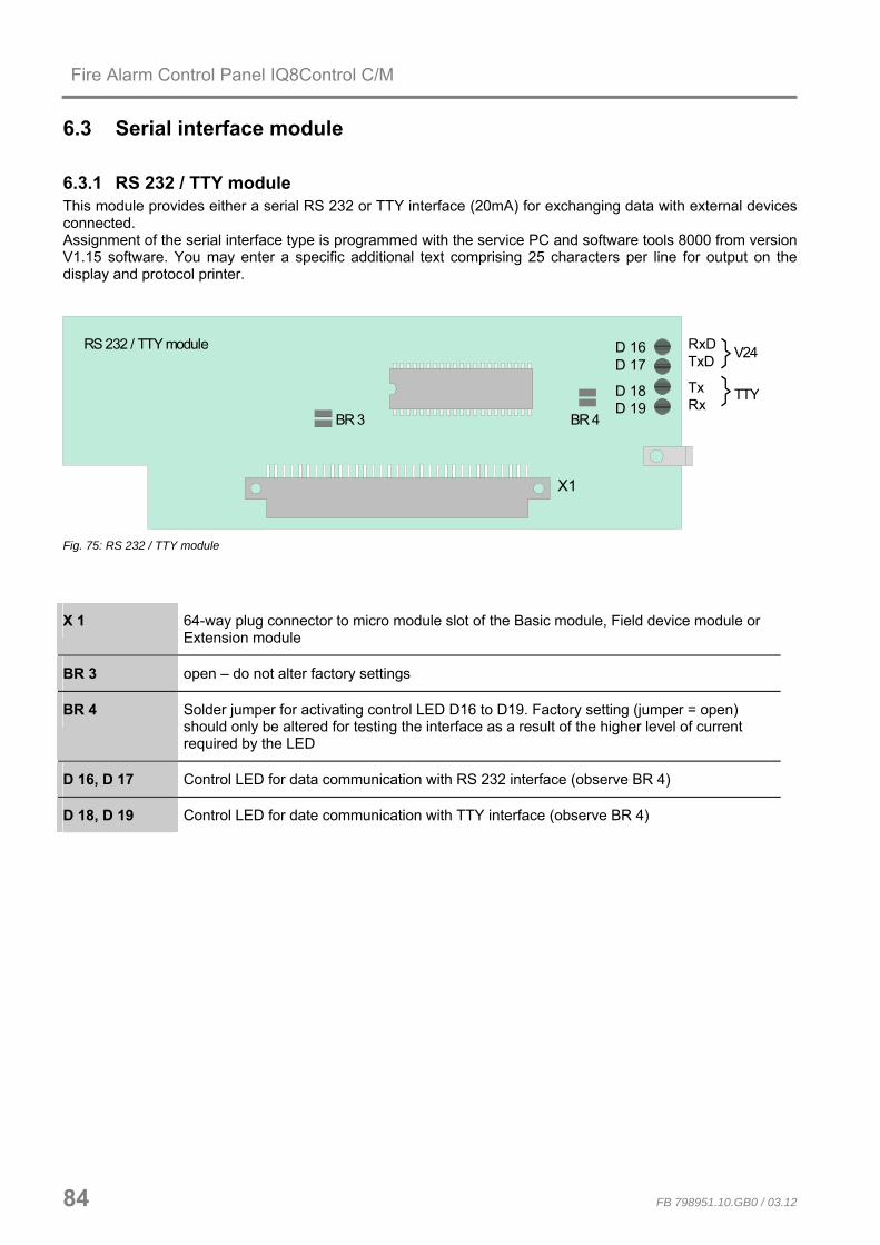
Fire Alarm Control Panel IQ8Control C/M
84 FB 798951.10.GB0 / 03.12
6.3 Serial interface module
6.3.1 RS 232 / TTY module This module provides either a serial RS 232 or TTY interface (20mA) for exchanging data with external devices connected. Assignment of the serial interface type is programmed with the service PC and software tools 8000 from version V1.15 software. You may enter a specific additional text comprising 25 characters per line for output on the display and protocol printer.
X1
D 16D 17
D 18D 19
BR 4
V24
TTY
RxDTxD
TxRx
RS 232 / TTY module
BR 3
Fig. 75: RS 232 / TTY module
X 1 64-way plug connector to micro module slot of the Basic module, Field device module or Extension module
BR 3 open – do not alter factory settings
BR 4 Solder jumper for activating control LED D16 to D19. Factory setting (jumper = open) should only be altered for testing the interface as a result of the higher level of current required by the LED
D 16, D 17 Control LED for data communication with RS 232 interface (observe BR 4)
D 18, D 19 Control LED for date communication with TTY interface (observe BR 4)

Fire Alarm Control Panel IQ8Control C/M
FB 798951.10.GB0 / 03.12 85
Assignment of terminal card RS232 module
12
3
4
5
6
7
8
not used
RxD (receive)
Data GND (potential free)
TxD (transmitt) RxDTxD
DataGND
external device
not usednot usednot used
not used
Fig. 76: Assignment of terminal card RS232 module
Max. cable length for RS 232 is 15 m, recommended cable: I-Y (St) Y x 2 x 0.8 mm
Assignment for terminal card TTY module
12
3
4
5
6
7
8
not used
Tx -
Rx +
Tx +
Rx -
transmitt
receive
transmitt
Rx -
Tx +
Rx +
Tx -
external device
not used
not used
not used
receive
Fig. 77: Assignment for terminal card TTY module If solder jumper BR3 is closed on the module, TTY interface may not be used.
Max. cable length for TTY is 1000 m, recommended cable: I-Y (St) Y x 2 x 0.8 mm

Fire Alarm Control Panel IQ8Control C/M
86 FB 798951.10.GB0 / 03.12
6.3.2 Technical data interface modules
RS 232/TTY module (Part No. 784842)
Operating voltage : Internal via the power supply module, + 5 V DC / +12 V DC
Quiescent current : TTY-mode approx. 55 mA @ 12 V DC
RS232-mode approx. 35 mA @ 12 V DC
Interface type : TTY (20mA) or RS232 selectable in panels date configuration
Transmission speed : max. 19200 bit/s
Terminals : removable, for max. 1,5 mm2
Interface cable length : TTY max. 1000 m
RS 232 max. 15 m

Fire Alarm Control Panel IQ8Control C/M
FB 798951.10.GB0 / 03.12 87
7 Master box activation module Micro module for activating a master box (MFAB) and alerting the relevant emergency services, such as the fire department. With the Fire Alarm Control Panel, a connection for a master box module is integrated in the Field device module. If a Field device module is not fitted, an MFAB control module can be used for the connection of a master box. Up to 10 MFAB may be operated within a common fire alarm system. The required operation must be programmed with the service PC and Programming software tools 8000 from version V1.15 software. For the MFAB relay, an individual additional text with 25 characters per line can be entered for the clear text display and the protocol printer.
X1
S 1
F 1
S 2
K 1
ON
12
34
BR1 BR2 BR3 BR4 BR5 BR6
MFAB activation module
Fig. 78: Master box activation module
X1 64-way plug connector to micro module slot of the Basic module, Field device module or Extension module
K1 Relay for switching the MFAB supply voltage, e.g., +12 V or +24 V (DC) max. contact rating max. 30 V DC / 1 A
F1 Electronic fuse (multifuse): to reset, de-energise for approx. 30 seconds at the relevant screw terminals on the terminal card
S1 Setting the master box activation mode:
Switch set to left Activation intermittent
Switch set to right Activation continuous
S2 DIL switch to select the activation time of the MFAB (see table next Page)
BR1, BR3 Hardware adjustment of MFAB activation (see following pages).

Fire Alarm Control Panel IQ8Control C/M
88 FB 798951.10.GB0 / 03.12
DIL switch S2
The time for the duration of the activation of the MFAB can be selected using DIL switch S2.
Selecting the activation time for the MFAB
ON
12
34
activation for approx. 6 seconds
ON
12
34
activation for approx. 2,5 seconds
ON
12
34
activation for approx. 1,5 seconds
ON
12
34
activation for approx. 0,25 seconds
This selection only becomes active when "intermittent activation"
is selected on switch S1!
CPU failure mode function
Even when the Fire Alarm Control Panel is in the CPU failure mode the master box will still be activated in the event of a fire alarm. It is not possible to reset the master box while the Fire Alarm Control Panel is in the CPU failure mode!
Switching off the master box
The activation of the MFAB can be inhibited, for example for service or maintenance work, on the control panel keyboard of the Fire Alarm Control Panel. An automatic switch-off of activation can be programmed in the customer data. When the Fire Alarm Control Panel is opened (cover contact), the master box will not be activated in the case of an event.
A switched off master box will not transmit an alarm message to assisting organisations (e.g. fire department) in the case of an event.

Fire Alarm Control Panel IQ8Control C/M
FB 798951.10.GB0 / 03.12 89
Wiring of the terminal card
F1
GND
+UBext.
12
34
5
67
8
+
K
K
not use
MFAB reset (+12 V or +24 V / 300 mA)
+ MFAB supply voltage
primary loop to MFAB (+MFAB)
unlock fire department box (switched to GND max. 300 mA)
MFAB acknowiedgment
MFAB (schematic circuit diagram)
MFABrelay
monitoring
FDKBunlock
fire dept. key box(schematic circuit diagram)
acknowiedgmentcontact
Fig. 79: Wiring of the terminal card The signal to enable the fire service key box (FDKB) is activated when the master box acknowledge signal (terminal 8 = MFAB acknowledge) from the Fire Alarm Control Panel is detected.
Optical displays of the master box
An activated master box can be identified by a steadily lit red LED Main Detector (MFAB) on the control panel of the Fire Alarm Control Panel. Intervening personnel such as the fire department have been notified. If it has been impossible to activate a master box due to an event, possibly because the MFAB was switched off, this is indicated on the control panel by the steadily lit red LED Notify fire department.

Fire Alarm Control Panel IQ8Control C/M
90 FB 798951.10.GB0 / 03.12
Inhibiting MFAB activation
The master box or master box relay will not be activated if,
• the cover contact (lock on outer hosing) is open. (factory setting of solder jumper on module: BR2 = open ; BR3 = closed). The customer data of the Fire Alarm Control Panel must be programmed under menu point Functional designation of the MFAB control module to suppress the activation of the master box when the cover contact is open.
• the operating panel keyboard has been enabled for operation (key-operated switch).
• the master box is disconnected.
• there is trouble with the master box.
Activation of the MFAB in dependency on the cover contact (BR2 and BR3)
The hardware adjustment of the activation of the master box is determined by the two solder bridges BR2 and BR3 on the MFAB control module. Factory setting Germany D configuration BR2 = open
BR3 = closed
The activation of the MFAB occurs in dependency on the customer data programming. If, for BR3 = closed example, activation has been suppressed in the menu point Functional designation of the MFAB control module when the cover contact is open, the master box will not be activated in the case of an event when the cover contact is open.
Configuration for the Netherlands NL BR2 = closed
BR3 = open
The activation of the MFAB occurs independently of the customer data programming. If, for example, activation has been suppressed in the menu point Functional designation of the MFAB control module when the cover contact is open, the master box will still be activated in the case of an event by hardware when the cover contact is open.

Fire Alarm Control Panel IQ8Control C/M
FB 798951.10.GB0 / 03.12 91
7.1 Technical Data Master box activation module (Part No. 784385)
Operating voltage : Internal via the power supply module, + 5 V DC / +12 V DC
Quiescent current consumption : approx. 10 mA @ 12 V DC (without monitoring)
approx. 15 mA @ 12 V DC (monitored)
Emergency operation : yes
Fuses : Multifuse 1 A
Relay K1 : 1 monitored change-over contact (e.g. MFAB activation) contact rating max. 30 V DC / 1 A Monitored resistance 50 to 1000 Ω
Activation time (relay K1) Continuously or pulsed (0,25 s / 1,5 s / 2,5 s or 6 s)
Output "MFAB reset“ : max. 300 mA (+12 V DC or +24 V DC), short-circuit proof
Output "FDKB unlock" : max. 300 mA short-circuit proof
Terminals : removable, for max. 1,5 mm2
Compatibility : The Interface modules may be operated on a free selectable micro module slot of the FACP IQ8Control.
For System 8000 fire alarm control panels the MB interface module may be used as a replacement devices.

Fire Alarm Control Panel IQ8Control C/M
92 FB 798951.10.GB0 / 03.12
7.2 Overview – micro module terminals
Basic moduleIQ8Control
X3
micro module1 2 3 4 5 6 7 8
Fig. 80: Overview – micro module terminals
Loop module esserbus® (Part No. 784382 / 784382.10 / 784382.D0) for max. 127 loop devices, e.g. Fire detectors IQ8Quad, series 9200 and esserbus®-transponders, dividable in 127 individual zones Quiescent current: approx. 25 mA. Total current for loop devices max. 40 mA
A +
A -
B -
B +
not used
1 2 3 4 5 6 7 8
not used
not used
not used
Loop module esserbus® PLus (Part No. 804382 / 804382.10 / 804382.D0) or max. 127 loop devices, e.g. Fire detectors IQ8Quad, series 9200, esserbus®-transponders and loop compatible alarm devices, dividable in 127 individual zones Quiescent current: approx. 25 mA. Total current for loop devices max. 180 mA
A +A -
B -B +
B-
B+
A-
A+
not used!
Master box activation module (Part No. 784385) To connect and control the MFAB operation. Quiescent current: approx. 15 mA.
1 2 3 4 5 6 7 8
not used
MFAB reset (+12V oder +24V/300mA)+MFAB supply voltage
PPrimary loop to MFAB (+MFAB)GND
unlock fire dept. box (max. 300mA)MFAB acknowiedgment

Fire Alarm Control Panel IQ8Control C/M
FB 798951.10.GB0 / 03.12 93
RS232 / TTY module (Part No. 784842) Serial interface, alternatively RS232- or TTY (20 mA) to connect external devices e.g. hazard management system, Printers, Remote indicator panels etc. Quiescent current: approx. 35 mA @i RS232 approx. 55 mA @i TTY
RxD (receive)
Data GND (potential free)
TxD (transmitt)not used
1 2 3 4 5 6 7 8
not used
not used
not used
not used
1 2 3 4 5 6 7 8
Tx - (transmitt)
Rx + (receive)
Tx + (transmitt)
Rx - (receive)
not usednot used
not used
not used
3 Relay module (Part No. 787531) Three bistable relay (monitoring possible) with programmable operation mode normally open or normally close. Contact rating: max. 30 V DC / 1A Quiescent current: approx. 5 mA
3 Relay common fault module (Part No. 787532) Three bistable relay (monitoring possible) with programmable operation mode normally open or normally close and an additional common fault relay (energized in normal mode). Contact rating: max. 30 V DC / 1A Quiescent current: approx. 15 mA
1 2 3 4 5 6 7 8
ext. device to relay K 1
ext. device to relay K 2
ext. voltage e. g. +12 V
-++
+
+
--
-ext. device to relay K 2
1 2 3 4 5 6 7 8
ext. device to relay K 1
ext. device to relay K 2
++
++
--
-
-
ext. voltage for ext. deviceto Relay K 1 e. g. +12 V
ext. voltage for ext. deviceto Relay K 2 e. g. +24 V

Fire Alarm Control Panel IQ8Control C/M
94 FB 798951.10.GB0 / 03.12
4 Relay module (Part No. 787536) Four dry relay contacts (not monitored) with programmable operation mode normally open or normally close. Contact rating: max. 30 V DC / 1A Quiescent current: approx. 10 mA. Total current per module max. 1 A
1 2 3 4 5 6 7 8
ext. device to relay K 1
ext. device to relay K 2
ext. device to relay K 3
ext. device to relay K 4
essernet® module 62.5 kBd (Part No. 784840 / 784840.10) network module for max. 16 network devices; telephone cable IY (ST) Y x 2 x 0.8mm Cable length between two devices max. 1000 m Quiescent current: approx. 170 mA.
essernet® module 500 kBd (Part No. 784841 / 784841.10) network module for max. 31 network devices; cable IBM type 1 or similar cables; Cable length between two devices max. 1000 m Quiescent current: approx. 150 mA.
1 2 3 4 5 6 7 8
L 1+L 1-
not used
L 2+L 2-
not used
not used
not used

798951.10.GB0 G 299044
03.2012 G 205129 Technical changes reserved! © 2012 Honeywell International Inc.
GB
Installation Instruction
Fire Alarm Control Panel IQ8Control C/M Commissioning / Maintenance

Fire Alarm Control Panel IQ8Control C/M
96 FB 798951.10.GB0 / 03.12
8 Installer level The Commissioning / Maintenance as well as Operations and Fire Alarm Control Panel functions which should only be performed by specialised installers or authorised persons are integrated under the menu options >Installer< in the Fire Alarm Control Panel IQ8Control C/M. The service level is protected from unauthorised access by a numeric authorisation code. This authorisation code is dependent on the >country function< programmed in the customer data. Pressing the Installer function key moved from the service level to the installer level. Before entry to the installer level, the authorisation code must be entered. (Exception: The requirement of the authorisation code has been deleted by the programming of the Customer data). The authorisation for operations in the Installer level remains active until the keyboard cover (key switch) is closed or no keyboard operation is carried out in the installer level for more than ten minutes. During this period, access is possible to the various display levels without further authorisation.
• The menu options >Installer< is only displayed in the service level ! • Indicated Display messages may differ due to object related programming.
A complete system check must be carried out after commissioning and for each modification of the customer data programming!
Authorisation code (by factory default)
The authorisation code programmed at works level through the Country function can be changed individually in the Customer data programming.
Code: 123 for programmes Country functions for (Germany, Great Britain, Switzerland and others)
20290 for programmed Country function for The Netherlands (NL) --- for programmed Country function for Austria
(no works programmed authorisation code)
Accsess Installer level
Code: * * * *
Escape Delete Select
Fig. 81: Entry of the authorisation code
• Press the function key >Service< (The display changes to the service level)
• Press the function key >Installer<
• Enter the authorisation code (e.g. -123- for the Country function Germany on the keyboard)
• Press function key >Select<
• The Function menu of the installer level appears
Correcting an input error
An incorrect entry can be corrected with the >Delete< function key. Following the fourth incorrect entry, the keyboard is blocked for approx. 60 seconds.
Installer code unknown
If the installer code is unknown or has been forgotten, it can be easily queried with the service PC. For this purpose, the Customer data is obtained from the control panel by the tools 8000 software. The max. 8-digit authorisation code is then displayed under menu options >Customer data - installer code< . Storage of the Customer data which has only been queried to obtain the installer code is not necessary.

Fire Alarm Control Panel IQ8Control C/M
FB 798951.10.GB0 / 03.12 97
The function menu of the installer level appears with four menu points:
The function menu of the installer level with its four menu points appears after the successful entry of the authorisation code:
Installer1 Primary loop functions2 Detector simulation3 Control simulation4 Printer function
Escape Event mem. Select
Fig. 82: Function menu Pressing the Escape function key exits the installer level to the status display.
1. Primary loop function
• Switching on/resetting a primary loop • Switching off a primary loop • Test operation of an loop • Detector replacement in an loop
2. Detector simulation
• Alarm simulation of a fire detector • Pre-alarm simulation of a fire detector • Trouble simulation of a fire detector • End test (simulation)
3. Control simulation
• Activate simulation of a control (relay/open collector output) • Trouble simulation of a control (relay/open collector output) • End test (simulation)
4. Printer functions
• Switching off the internal or external protocol printer • Switching on the internal or external protocol printer • Print out the event memory / repeat printout • Display event memory

Fire Alarm Control Panel IQ8Control C/M
98 FB 798951.10.GB0 / 03.12
8.1 Primary loop function
Primary loop function
Under this menu point, the internal primary loops of this Fire Alarm Control Panel or other Fire Alarm Control in an essernet® network can be switched on or off and checked by a manual test function. Additionally, it is possible to replace single detectors in operative loops e.g. during maintenance work.
Primary loops are: • all ring modules included in this FACP
(including the loop connected to this module with all bus devices)
• all four-zone-modules included in this FACP (including all detector zones and detectors connected to this module)
• certain modules, such as relays or the interface on the basis/peripheral module
Connector and corresponding Primary loop number
Individual assemblies of the Panel can be switched on/off with the internal primary loop number through the control panel keyboard or programmed with programming software. This internal primary loop number is composed of the control panel number, the slot and the assembly number (ref to Chapter 3.4).
Primary loop / transfer routePrimary loop : 121
Escape Function
1 Switch on / reset2 Switch off3 Test4 Replace detector
Fig. 83: Switching on / resetting a primary loop
• N Enter the number of the primary loop to be switched on and press the Select function key
• Enter the number of the desired function (1 = Switching on/reset) or select the menu options >Switching on/Reset< with the cursor keys and press the >Function key<
The primary loop is switched on and indicated on the display with a message.
Switching off a primary loop
• Enter the number of the primary loop to be switched off and press the Select function key
• Enter the number of the desired function (2 = Switching off) or select the menu options >Switching off< with the cursor keys and press the >Function< key
The primary loop is switched off and indicated on the display with a message. In the switched off state of a primary loop, the yellow LED >Collective switch-off< lights in addition to the display message. The displays and controls programmed in the Customer data of the Fire Alarm Control Panel for the function Switch-off are activated.
When a primary loop is switched off, all detector zones and fire detectors connected to this module are also switched off. Switched off fire detectors will not signal an alarm in the case of an event !

Fire Alarm Control Panel IQ8Control C/M
FB 798951.10.GB0 / 03.12 99
8.2 Testing (the loop)
Primary loop / transfer routePrimary loop : 121
Escape Function
1 Switch on / reset2 Switch off3 Test4 Replace detector
Fig. 84: Testing the loop
• Enter the number of the loop to be tested and press the Select function key.
• Enter the number of the desired function (3 = Testing) or select the menu options >Test operation< with the cursor keys and press the >Function< key.
An loop in test operation will not signal an alarm in the case of an event!
The Function >Testing< is not carried out when ...
• the loop is switched off.
• the loop module is defective.
Testing an loop
The test operation must be carried out individually for each loop or detector zone. The simultaneous testing of several loops/detector zones is impossible. By this menu point, the selected loop (including all detectors and esserbus® transponders) or single detector zones in the loop are tested for the following functions:
• Malfunctions of one or more detectors / esserbus® transponders.
• Malfunction of the switch-on control (SOC) by automatic detectors.
• Conformance of the addresses with the Customer data programming (if necessary, the detector data is automatically updated).
• Conformance of the loop wiring with the Customer data programming.
• Conformance of detector types and external wiring with the Customer data programming.

Fire Alarm Control Panel IQ8Control C/M
100 FB 798951.10.GB0 / 03.12
8.3 Detector replacement
Replacement of fire and diagnostic detectors (4-zone module)
Diagnostic fire detectors can be replaced without adjustment of the detector address on the base circuit board or overwriting data with the service PC. The menu options >Detector replacement< is inoperable for these detectors.
Replacement of intelligent detectors Series 9200 (loop)
Any number of detectors series 9200 / IQ8Quad or esserbus® transponders in an loop can be replaced. The replacement of detectors can be carried out in many cases without the service PC. (See table) At the control panel
Using the table on next page,find out whether the replacement can be carried out
without the service PC.
At the control panel
no
yes
At the location of the detector
Wait until the display "TEST" for the primary loop go out.
Have malfunctions occurred?
no
Replacement of detectors is completed.
yes
Check the execution of the replacement and reactivateReplace detector function.
Switch the primary loop, detector zone or detector. Replacement
of detectors is completed.
connect service-PC andcarry out automatic wiring
ring loop.
Enter the installation code, select primary loop function, enter the primary loop number and select
function 4 "replace detector".On the primary loop all zones and the Primary loop
are indicated on the display with "TEST"
Which trouble code appearsin the display ?
see section 11 (detector malfunctions).
no
yes
Exchange all detectors which are to be replaced in the loop. Screw the new detectors tightly into
the detector bases, do not damage connecting cables.
Enter the installer code, select primary loop function, enter the primary loop number and
select function 2 "swich off"
Is this malfuntion due to the replacement
of detectors?
Fig. 85: Flow diagram of detector replacement

Fire Alarm Control Panel IQ8Control C/M
FB 798951.10.GB0 / 03.12 101
Type/extent of the detector replacement without
Service-PC * displayed
trouble code
The type and external switching of the exchanged detector are in conformance. For example, if a defective OHI-detector without a detector base output is replaced with a new OHI-detector without a detector base output.
yes ---
The detector type changes , the external switching remains the same. For example, an optical smoke detector is replaced with an OHI- detector and the existing external wiring is not changed.
yes St : 081-087/ 095
During the replacement of detectors, the external switching is removed; the detector type remains unchanged. For example, an OHI-detector with a relay output is replaced with an OHI-detector without a relay output. The change in the external switching from relay to LED outputs (or the converse) is not recognised.
no St : 088
During the replacement of detectors, the external switching is added, the detector type remains unchanged. For example, an OHI-detector without a relay output is replaced with an OHI-detector with a relay output. The change in the external switching from relay to LED outputs (or the converse) is not recognised.
yes St : 089
An isolating circuit is removed, the detector type remains unchanged. For example, an OHI-detector with an isolating circuit (zone isolator) is replaced with an OHI-detector without an isolating circuit.
no St : 088
An isolating circuit is inserted, the detector type remains unchanged. yes St : 090
The wiring of the loop is changed. For example, during the replacement of detectors, a new detector is inserted in an additional spur loop. no St : 066
Replacement of identical esserbus® transponders. A defective esserbus® transponder Type 12 relay is replaced with an identical esserbus® transponder. The programming of the 12 relay outputs is not changed.
yes ---
Replacement of dissimilar esserbus® transponders. An esserbus® transponder is replaced by another type or the designation / programming of the outputs is changed.
no St : 080
Replacement of an esserbus® transponder with an automatic detector and the converse. no St : 080
Replacement of a manual call point with an esserbus® transponder and the converse. no St : 080
* Operation without Service-PC available in the installer level of the Fire Alarm Control Panel IQ8Control C/M.

Fire Alarm Control Panel IQ8Control C/M
102 FB 798951.10.GB0 / 03.12
8.4 Simulation of detector states Under this menu point, the state of addressable detectors of the series 9100, 9200 and IQ8Quad (no esserbus® transponder) can be simulated for test purposes. In all non-addressable detectors (Series 9000), the detector zone state is simulated. With the simulation of a detector state for test purposes, all programmed displays and controls corresponding to this detector and state in the Customer data of the Fire Alarm Control Panel are activated.
Self-control of the detectors series 9200 / 9200 / IQ8Quad
An intelligent fire detector can be operated in connection with a detector base output (relay or open collector). If a control has not been programmed in the Customer data of the Fire Alarm Control Panel for this detector, the integrated detector base output is activated during the simulation of the "Alarm" state.
Status Repeat Select
AlarmPre-alarmTroubleEnd test
Detector simulation
Detector :: Zone
Fig. 86: Entering the zone and detector number
Status Function
1 Alarm 2 Pre-alarm 3 Trouble 4 End test
Detector simulation
Detector : 20: 12Zone
Fig. 87: Selection of the detector status for simulation • Enter the zone and detector number of the fire detector or TAL module. • Press the >Select< function key. • Enter the number for the desired function ( 1 = Alarm, 2 = Pre-alarm, 3 =Trouble, 4 = End test) or select with
the cursor keys and press the function key >function< to acknowledge the input.
To end this simulation
Each individual detector (or zone) whose operating state has been simulated must be terminated with the End test function!
This function pertains exclusively to the detectors of this (local) control panel. The simulation of detector states in the essernet® network is impossible. Simulation of individual detectors or zones is not supported via communications transponder (Part No. 808615) of the 8010 extinguishing control system.
Dependant on the programming of the control panel, the master box and any other external alarm devices are activated during the state simulation of a fire detector.
* By pressing the >Repeat< key, the displayed detector number is incremented by the value "+1", without the need of entering the number of the new (next higher) zone/detector number on the keyboard.

Fire Alarm Control Panel IQ8Control C/M
FB 798951.10.GB0 / 03.12 103
8.5 Simulation of control states Under this menu point, the state of any control, such as relays or open collectors, can be simulated for test purposes. The simulation of control states in an essernet® network is impossible. The function pertains exclusively to controls which are allocated to this Fire Alarm Control Panel and are programmed in the customer data with a control zone number, such as:
• Relay or open collectors of the micro modules of these FACP
• Detector base outputs of fire detectors Series 9100
• Detector base outputs of fire detectors Series 9200 / IQ8Quad
• Controls of esserbus® transponders in the loop With the simulation of a control state, all programmed displays and controls for this control and state are activated or deactivated. (Observe customer data programming).
Status Repeat Select
ActivationTroubleEnd test
Control simulation: Control
Fig. 88: Entering the control number
Status Function
1 Activation 2 Trouble 3 End test
Control simulation: 15Control
Fig. 89: Selecting a function
• Enter the control number of the corresponding open collector or relay
• Press the Select function key
• Enter the number for the desired function ( 1 = Activate, 2 = Trouble, 3 = End test) or select with the cursor keys and press the function key >function< to acknowledge the input
To end this simulation, each individual control whose operating state has been simulated must be terminated with the End test function!
For the master box controls (Control numbers 1 to 10), a simulation is impossible! Simulation of individual detectors or zones is not supported via communications transponder (Part No. 808615) of the 8010 extinguishing control system.
* By pressing the >Repeat< key, the displayed control number is incremented by the value "+1" without the need of entering the new (next higher) control number on the keyboard.

Fire Alarm Control Panel IQ8Control C/M
104 FB 798951.10.GB0 / 03.12
8.6 Query of additional and info texts of other control panels (remote text)
With this function, the programmed additional and info text for controls, detector zones or detectors of any Fire Alarm Control Panel in the essernet® network can be queried and shown on the display. This remote text query can also be carried out by the operator. If an event is imminent for which additional or info text has been programmed, this is automatically displayed as remote text.
Operator Func. menu Rem. Text
1. ACTIVATED Control : 015
1. ACTIVATED Control : 001
10:10 22.07
10:16 22.07
Fig. 90: Status display with the “ Rem. Text“ menu point
Text request from control panel XX
Fig. 91: Access to programmed additional and info text
If additional or info text has not been programmed for this detector or control in the other Fire Alarm Control Panel, an empty line is displayed by the >Rem.text< function.

Fire Alarm Control Panel IQ8Control C/M
FB 798951.10.GB0 / 03.12 105
8.7 Printer function Under this menu point, the protocol printer connected to the Fire Alarm Control Panel (internal printer and/or external serial printer) can be switched on or off. In addition, the contents of the internal event memory of the control panel can be printed out on a local protocol printer.
The activation of other control panel printers in the essernet® network is impossible.
Internal protocol printer
The internal protocol printer is selected with a (max.) four-digit number. This number consists of the control panel number (e.g. 1 to 31 in an essernet® network) and the number "01". Example: panel number 01 Nr. of the internal protocol printer 0110 panel number 05 Nr. of the internal protocol printer 0510
External protocol printer
The external protocol printer is selected by the primary loop number of the interface micro module (RS 232/TTY module) to which the printer is connected. The number of the interface module consists of the number of the Fire Alarm Control Panel, the micro module board and the slot in which the RS232/TTY-Module is fitted in the same way as the primary loop number.
Switching off the protocol printer
By the first activation of the menu options >Printer function<, the printer number is automatically allocated to the internal protocol printer if installed. This allocation can be removed by pressing the >Zone< key.
Func.menu Repeat Select
Switch offSwitch onPrint event mem
Printer: Printer
Fig. 92: Function menu
• Enter the number of the printer which is to be switched off (primary loop number of the serial interface) and press the >Select< function key
• Enter the number of the desired function (1 = Switching off) or select the menu options Switching off with the cursor keys and press the >Function< key

Fire Alarm Control Panel IQ8Control C/M
106 FB 798951.10.GB0 / 03.12
Switching on the protocol printer
Func.menu Repeat Select
Switch offSwitch onPrint event mem
Printer: 0110Printer
Fig. 93: Entering the number of the external (serial) printer
• Enter the number of the printer which is to be switched on and press the >Select< function key.
• Enter the number of the desired function (2 = Switching on) or select the menu options >Switching on< with the cursor keys and press the >Function< key.
Printing out the event memory
The last 200 entries of the 10,000-entry circulating archive are printed on the log printer from the internal event memory.
Func.menu Repeat Select
Switch offSwitch onPrint event mem
Printer: 0110Printer
Fig. 94: Printer function – printing out the event memory
• Enter the number of the protocol printers on which the contents of the event memory are to be printed out and press the >Select< function key.
• Enter the number of the desired function (3 = Print event memory) or select the menu options >Event mem.< with the cursor keys and press the >Function< key.
A switched off protocol printer will not print messages or events !

Fire Alarm Control Panel IQ8Control C/M
FB 798951.10.GB0 / 03.12 107
8.8 Display of the event memory At the installer level, the event memory of the Fire Alarm Control Panel can be shown on the control panel display by pressing the >Event mem< key. The last 200 events, such as alarms, malfunctions, switch-offs and operating authorisations are stored in the event memory in chronological order. The display shows the latest event. The events are automatically numbered with consecutive report numbers. The higher the report number, the more recent is the event (report number 001 = oldest event).
End Print
Signal 078
10:12 17.10wire brk.
Event memory
Zone : 004 Detector : 013rd floor, conference room
TROUBLE
Fig. 95: Event memory It is possible to browse the event memory for individual events using the cursor keys.
Fig. 96: Cursor keys
10 events forward To next younger event 10 events backwards To next older event
Printing the contents of the event memory
Pressing the >Printing< function key moves automatically to the >Printer functions< menu. If an internal protocol printer is installed, the printer number is automatically allocated to this Printer. This allocation can be removed by pressing the >Zone< key and the desired printer number, e.g. for an external protocol printers, can be entered. All entries (max. 200) of the event memory are printed out ordered from the most recent to the oldest event. (see “Printing out the event memory“).

Fire Alarm Control Panel IQ8Control C/M
108 FB 798951.10.GB0 / 03.12
9 Diagnostic display
9.1 Diagnostic display IQ8Control C/M The diagnostic display enables, e.g. a fast check of the power supply values of this Fire Alarm Control Panel for service and maintenance work. In the control panel IQ8Control C/M display, a diagnostic field with individual measured values (analog measurement channels) which are automatically determined by the control panel is displayed.
Key press sequence for switching on the diagnostic display Test-Test-F4-3
Press key
F4Test
3Test
Analog 0Analog 4Analog 8Analog 12
Analog 1Analog 5Analog 9Analog 13
Analog 2Analog 6Analog 10Analog 14
Analog 3Analog 7Analog 11Analog 15
Fig. 97: Panel power supply values
The display is structured in a matrix for a quick survey. The significance of the individual analog channels is shown in the table below.
Analog channel Description Voltage limits Range of values
Analog 0 Micro module on the Basic module ---* ---* Analog 1 Micro module plug 1 on the Extension module ---* ---* Analog 2 Micro module plug 2 on the Extension module ---* ---* 1* Analog 3 Micro module plug 3 on the Extension module or
Micro module plug on the Peripheriemodul ---* ---*
Analog 4 Micro module plug 1 on the Extension module ---* ---* Analog 5 Micro module plug 2 on the Extension module ---* ---* 2* Analog 6 Micro module plug 3 on the Extension module ---* ---* Analog 7 Test channel 2,5V ± 2% 120 to 135 Analog 8 Power supply, Secondary voltage 12V DC 10V to 15V 82 to 152 Analog 9 Battery _1 10V to 14V 121 to 168
Analog 10 Battery _2 10V to 14V 121 to 168 Analog 11 Ubextern 12V DC 10V to 15V 82 to 152 Analog 12 ULinie + 27,5V oder +42 Volt 26V to 29V 108 to 149 Analog 13 Ground fault 10,5V to 14,6V 60 to 120 Analog 14 Monitoring IN1 (e. g. External power supply) 4 V 65 to 255 Analog 15 Monitoring IN2 (e. g. External power supply) 4 V 65 to 255
* = values relating to the fitted micro module type (value range date 09/2005) 1* = System connector 1 2* = System connector 2
Switch off the diagnostic display with function key F1 or F4
Press key
F1 F4

Fire Alarm Control Panel IQ8Control C/M
FB 798951.10.GB0 / 03.12 109
9.2 The essernet® diagnostic line The essernet® connection of the various units in the network can be checked with this diagnostic line. The essernet® diagnostic line (L:xxx) indicates which connections are functioning correctly (standard operation) and which have malfunctioned. Non existent units/ control panels are represented by the character "?". The status display at the beginning of the line (0,S,E or B) indicated whether data calibration is in progress between two control panels. This is always the case when signals are updated in the essernet®, for example when a switched off control panel is switched back on or when a new control panel is integrated in the essernet® network and its data is automatically updated. Which control panel is conducting this data calibration can be determined by the two-digit control panel number (part: xx).
Switching on the essernet® diagnostic line
Press key
F4Test
1Test
Approx. 5 seconds after switching on, the essernet® diagnostic line appears in the display. Once selected, the diagnostic line remains visibly in the display in all menu levels, for example when changing to the status display, the installer level or when scrolling the contents of the display, until it is deactivated.
Switching off the essernet® diagnostic line
Press key
F4Test
2Test
After approx. 5 seconds, the display of the essernet® diagnostic line is switched off.
Display contents and their significance
0 Zxx Pxx L:00021??????????????????????????
Control number (01 to 31) of the FACP with which data calibration is in progress
Decimal display (00 to 99) of the communication status (only factory use)
Status of the data calibration
0 = data calibration OKS = Control panel is transmittingE = Control panel is receivingB = Data calibration terminated/faulty
essernet® status list for control panel No. 1 to 310 = essernet connection OK1 = no data from terminal 3 + 4 (short circuit/open connection)2 = no data from terminal 1 + 2 (short circuit/open connection)9 = no communication between FACP and essernet® module? = customer data not programmed
Fig. 98: Display and significance

Fire Alarm Control Panel IQ8Control C/M
110 FB 798951.10.GB0 / 03.12
Example of essernet® diagnostic line with four Fire Alarm Control Panels
In the illustrated example, four Fire Alarm Control Panels are interconnected in the essernet®.
Panel No. 3
Panel No. 4 Panel No. 2
Panel No. 1
Trouble
essernet®
L : 0 2 1 0 ???????????????????
control panel no.1control panel no.2control panel no.3control panel no.4control panel no. 5-31 non existant
Fig. 99: Example essernet® diagnostic line with four control panel The connection between control panel No. 2 and No. 3 is faulty due to an open line, a short circuit or incorrect wiring. Panel no. 5 to 31 are displayed with the ?-sign, because the they are not programmed in the customer data.
During the display of the essernet® diagnostic line, status messages such as >MB switched off< or >Acoustics switched off< are not shown in this line of the display.

Fire Alarm Control Panel IQ8Control C/M
FB 798951.10.GB0 / 03.12 111
9.3 Checking the essernet® devices and connections An additional check of the essernet® devices/connections can be carried out using the essernet® micro modules (Part No. 784840 / 784841 from index “E” onwards).
Switching on the display on the fire alarm control panel:
Press key
F3Test
6Test
The displays are switched off using the key switch.
Display Value (example)
Meaning
Direction 12 1555 Number of telegrams received without error at terminals 1+2 of the essernet® micro module. Automatic update of the values: essernet® micro module 62.5 kBd: every 45 seconds essernet® micro module 500 kBd: every 10 seconds
Direction 34 1551 Terminals 3+4 (see “Direction 12”) Fault 12 [%] 0 Percentage display of the faulty telegrams which are received at
terminals 1+2 of the essernet® micro module. Automatic update of the values: essernet® micro module 62.5 kBd: every 45 seconds essernet® micro module 500 kBd: every 10 seconds
Fault 34 [%] 0 Terminals 3+4 (see “Fault 12”) Fault. Max 12 [%] 6 Maximum percentage value of the faulty telegrams received at terminals
1+2 since the panel was last restarted. This function enables a measurement over a longer period and is reset to “0” after every restart of the FACP.
Fault. Max 34 [%] 8 Terminals 3+4 (see “Fault. Max 12”) Repeat telegram 4 Number of repetition requests.
Repetition requests for telegrams are a sign that there are faults on a module or on the transmission path.
Panel no. 10 Display of the micro module address which has been set on the essernet® module. This address must correspond to the customer data of the FACP.
The counters are reset when the FACP is restarted.

Fire Alarm Control Panel IQ8Control C/M
112 FB 798951.10.GB0 / 03.12
9.3.1 Checking the essernet® devices and connections An additional check of the essernet® devices/connections can be carried out using the essernet® micro modules (Part No. 784840.10 / 784841.10 - from index “E” onwards). Switching on the display on the fire alarm control panel:
Press key
F3Test
6Test
The display will automatically alter from indication on side 1+2. By turning the key switch (unlock keyboard) the display is set to normal indication mode.
Display page 1 Value (example)
Meaning
Terminal 12 1555
Number of telegrams received without error at terminals 1+2 of the essernet® micro module. Automatic update of the values: - essernet® micro module 62.5 kBd: every 45 seconds - essernet® micro module 500 kBd: every 10 seconds
Terminal 34 1551 Terminals 3+4 (see “Terminal 12”)
Fault 12 [%] 0
Percentage display of the faulty telegrams which are received at terminals 1+2 of the essernet® micro module. Automatic update of the values: - essernet® micro module 62.5 kBd: every 45 seconds - essernet® micro module 500 kBd: every 10 seconds
Fault 34 [%] 0 Terminals 3+4 (see “Fault12”)
FtMax 12 [%] 6 Maximum percentage value of the faulty telegrams received at terminals 1+2 since the panel was last restarted. This function enables a measurement over a longer period and is reset to “0” after every restart of the FACP.
FtMax 34 [%] 8 Terminals 3+4 (see “FtMax 12”)
Rep. Telegr 4 Number of repetition requests. Repetition requests for telegrams are a sign that there are faults on a module or on the transmission path.
PanelNo. 10 Display of the micro module address which has been set on the essernet® module. This address must correspond to the customer data of the FACP.
Display page 2
Level 12 33
Value range at terminal 1+2 from 0 to 100. Values from 10 to 100 normal operation Values below 10 fault The yellow LED onto the module lits. Furthermore the message will be displayed as >common fault< and indicated in the display with >Sys. fault essernet<.
Level 34 66 terminals 3+4 (refer to “Level 12”) - - - -
--- ---
Version 500000 Software Version V5.00R00 of the essernet®- module
PanelNo 10 Address setting of the essernet® module – This address must match the selected address in the FACP software configuration.
The counters are reset when the FACP is restarted.

Fire Alarm Control Panel IQ8Control C/M
FB 798951.10.GB0 / 03.12 113
9.4 Display of the analogue values For service and maintenance work, the current analogue values for all micro modules and components of the device module can be displayed to check the FACP. The following tables show the individual micro modules, each with the valid range of analogue values. A fault is detected if the current measured value is outside the valid value range during checking. Analogue value is too large: Short circuit/the current flow is too high in this component Analogue value is too small: Interruption/contact problem in this component
Switching on the display
Press key
F3Test"IO No."
Test
"IO no." IQ8 Control: 1 = basic module 2 = extension module plug 1 2 = extension module plug 2
selected module (I/O no.)
1 Ana 12 Ana 13 Ana 1
Ana 2Ana 2Ana 2
Ana 4Ana 4Ana 4
Ana 5Ana 5Ana 5
Ana 3Ana 3Ana 3
* with basic module *with device module *with extension module 1 SAS relay 1 3 relay 1 Micro module slot 1 2 Serial interface 2 Transmission device 2 Micro module slot 2 3 Micro module 3 Primary loop 3 Micro module slot 3 Fig. 100: Diagnostics display
Switching off the display
Press key
F1 F4or

Fire Alarm Control Panel IQ8Control C/M
114 FB 798951.10.GB0 / 03.12
* 3 relay module/3 relay module CF
Analog channel Function Normal value range FACP
IQ8Control Ana 1 Relay 1 93 ... 141 Ana 2 Relay 2 93 ... 141 Ana 3 Relay 3 93 ... 141 Ana 4 Not occupied 00 Ana 5 Not occupied 00 * Ana 1 ... Ana 3 = "0" in the case of inverse, unmonitored or activated relays
* Master box activation module
Analog channel Function Normal value range FACP
IQ8Control
Ana 1 Monitoring input 50 to 300 Ohm 301 to 1000 Ohm
27...100 35...150
Ana 2 Not occupied 00 Ana 3 Not occupied 00 Ana 4 Not occupied 00 Ana 5 Not occupied 00 * Ana 1 = “0” in the case of activated transmission device * Loop module
Analog channel Function Normal value range FACP
IQ8Control Ana 1 Emergency mode monitoring, module 00 ... 27 Ana 2 Not occupied 00 Ana 3 Not occupied 00 Ana 4 Not occupied 00 Ana 5 Not occupied 00 * Ana 1 = “0” if module is not in emergency mode

Fire Alarm Control Panel IQ8Control C/M
FB 798951.10.GB0 / 03.12 115
* Master box, internal (device module)
Analog channel Function Normal value range FACP
IQ8Control Ana 1 Monitoring input, master box (K1) 14 ... 185 Ana 2 Not occupied 00 Ana 3 Not occupied 00 Ana 4 Not occupied 00 Ana 5 Not occupied 00 * Ana 2 = “0” with activated master box *
* 3 relay, internal (device module)
Analog channel Function Normal value range FACP
IQ8Control Ana 1 Relay 1 (K2) 70 ... 120 Ana 2 Relay 2 (K3) 70 ... 120 Ana 3 Relay 3 (K4) 70 ... 120 Ana 4 Not occupied 00 Ana 5 Not occupied 00 * Ana 1 ... Ana 3 = “0” with inverse or activated relays *0
Primary loop, internal (device module)
Analog channel Function Normal value range FACP
IQ8Control Ana 1 Monitoring input 70 ... 120 Ana 2 Not occupied 00 Ana 3 Not occupied 00 Ana 4 Not occupied 00 Ana 5 Not occupied 00

Fire Alarm Control Panel IQ8Control C/M
116 FB 798951.10.GB0 / 03.12
10 Meaning of the three digit error codes / test mode A three digit error code is displayed in the display in case of a failure of an intelligent fire detector. The meanings of these codes and measures for correcting the error condition are given in the following table.
Error indication in case of detector replacement
During detector replacement, the display shows error codes which have to comply with the modifications done. If error messages remain after the detector replacement has been completed the cause of the trouble can be identified quickly with the help of the 3 digit error code (ref. tables below).
Trouble Code No. Possible cause 1st. measure 2nd. measure
001 002 003
Detector is faulty. Exchange detector. Return faulty detector to manufacture.
004 Strong electromagnetic disturbances or detector faulty.
Check the detector with programming software tools 8000, check installation place if necessary.
Return detector for controlling to manufacture.
005 Ambient light too bright at location where detector is installed.
Check whether detector is exposed to source of bright light. Change location if necessary.
If fault re-occurs on this detector, detector should be returned to manufacture for inspection.
006 007 008
Detector is contaminated or moist.
Clean detector and check with tools 8000. ---
009
Strong electromagnetic disturbances of the visual sensor in the area of 8 - 60 kHz (> 50 V / m).
Disturbance is caused by an electrical consumer in immediate proximity of the detector. Moving detector if necessary.
One coupling of the disturbance about the record circuit. Checks whether record circuit was transferred parallely to power lines.
1) An electrically leading substance caused a short-circuit in the I-chamber.
Clean I-chamber and check it with programming software tools 8000. Noticing salt or fraying deposits.
Replace detector and return to manufacture.
2) CO sensor is overloaded with a high CO concentration.
Check if the detector is exposed to a high CO load. If necessary, reset the detector and recheck. The CO sensor should have at least 15 minutes to return to its quiescent values before rechecking. Check the CO concentration at the location of the detector and move the detector if necessary.
Return faulty detectors to the manufacturer.
3) Strongly pulsed high frequency fields.
If necessary, check installation location.
Return detector to manufacturer for checking.
010
4) Short circuit on the CO sensor. Replace detector. Return faulty detectors to the
manufacturer.
1) Detector is contaminated with dust or similar.
Clean detector and check it with programming software tools 8000.
Using an other detector type. 011
2) CO sensor is faulty. Replace detector. Return faulty detectors to the manufacturer.

Fire Alarm Control Panel IQ8Control C/M
FB 798951.10.GB0 / 03.12 117
Trouble
Code No. Possible cause 1st. measure 2nd. measure
1) Detector is soiled or damp.Clean detector and check it with programming software tools 8000.
Check the installed detector if the surrounding area is humid. Use protective measures if necessary, e.g. series 9x00 detectors: surface mount adapter 781495 or 781497/98 uses base adapter.
012
2) CO sensor is faulty. Replace detector. Return faulty detectors to the manufacturer.
1) Air speed too high at site of installation.
2) Detector is soiled with conductive substance and may be installed in damp environment.
Clean detector and check it with programming software tools 8000.
Using an other detector type.
013
3) CO sensor has temporarily left its working range (e.g. due to oversaturation).
Reset detector and recheck. If the error occurs again, return detector to manufacturer for checking.
014 Short-circuit at the temperature sensor.
Replace detector and return to manufacture. ---
015
1) Faulty bonding of the temperature sensor.
2) First installation at a cool place.
Adjust detector to ambient temperature with programming software tools 8000.
Replace detector and return to manufacture.
016 see 001 --- ---
017
1) Detector is soiled with a conductive substance or installed in damp surroundings.
2) Faulty detector.
Clean detector and check it with programming software tools 8000.
Replace detector and return to manufacture.
3) CO sensor is faulty. It is possible that the rel. humidity is always at a very low value in the area surrounding the detector.
Replace detector. Return faulty detectors to the manufacturer.
018
1) Detector is soiled with a conductive substance or installed in damp surroundings.
2) Faulty detector.
Clean detector and check it with programming software tools 8000.
Replace detector and return to manufacture.
1) Detector is soiled with oily substance.
Clean detector and check it with programming software tools 8000.
--- 019
2) CO sensor is faulty. Replace detector. Return faulty detectors to the manufacturer.
020 021
Current levels not correct on loop.
Check numbers of detectors, loop resistor and loop length. Check detector base wiring.

Fire Alarm Control Panel IQ8Control C/M
118 FB 798951.10.GB0 / 03.12
Trouble
Code No. Possible cause 1st. measure 2nd. measure
022 Detector unable to correctly activate its base circuit board. Check detector base wiring. ---
023 Detector unable to correctly activate its base circuit board.
1) Fault occurs while loop is being switched on: switch off loop and switch back on again after 1-2 minutes.
2) Fault occurs while switching the base output: check for connection of the freewheeling diode necessary for an inductive load. Pay attention to switching capacity of output.
3) Check whether the detector is installed in a damp environment.
Take any necessary protective measures, e.g. use mounting plate 781495 or base adapter 781497/98.
024 Detector unable to correctly activate its base board.
Check whether detector is installed in a damp environment.
Clear detector and re-check. Take protective measure if necessary, e.g., using mounting plate 781495 or 781497/98.
025 A manual call point has detected a short-circuit on its external D-line.
Check wiring of this D-line for short circuit. ---
026 An D-detector has recognised a wire break on its external D-line.
Check wiring of this D-line for open circuit. ---
027 see 011 --- ---
028 The detector has detected a short-circuit behind its cut-off relay.
Two detectors present with this trouble ⇒ search for loop short circuits between the two detectors.
One detector present with this trouble ⇒ loop short circuit between detector and panel.
029 The sounder of the IQ8Quad detector is defective.
Replace IQ8Quad detector and return to manufacture. ---
030 The IQ8Quad detector cannot emit the specified signal tone.
1. Check that the acoustic signal is supported by the IQ8Quad detector.
2. Check if the customer data has been programmed correctly.
Notify Customer Service.
033 034 035
see 001 --- ---
036 see 004 --- ---
037 esserbus® transponder has identified fault with its external voltage.
Check whether the external switching voltage of the esserbus®
transponder is in the correct voltage range.
---

Fire Alarm Control Panel IQ8Control C/M
FB 798951.10.GB0 / 03.12 119
Trouble
Code No. Possible cause 1st. measure 2nd. measure
038 esserbus® transponder has identified fault with its external voltage.
Check whether the external switching voltage of the esserbus® transponder is in the correct voltage range.
---
039
Communication between esserbus® transponder and panel has been disturbed for 100 seconds.
Notify Customer Service. ---
043
Communication between esserbus® communication transponder 808615 and the 8010 fire and extinguishing panel has been malfunctioned for over 100 seconds.
Check correct functioning of the 8010 fire and extinguishing panel. Correct any malfunctions of the fire and extinguishing panel and switch on the esserbus® -communication transponder via the FACP keyboard.
Notify Customer Service.
044
Communication between FACP and esserbus® communication transponder for the 8010 fire and extinguishing panel has been malfunctioned.
Notify Customer Service. ---
048 see 001 --- --- 052 / 053 see 020 --- ---
060 see 028 --- ---
060 Short circuit detected behind the isolator of the transponder.
see 028 see 028
062 Failure of the internal data communication of the transponders CPU.
Switch-on transponder or loop. If error occurs again refer to 2nd measure.
Press reset button on the transponder board, or disconnect transponders supply voltage. If error occurs again replace transponder.
063 Detector data assignment incomplete or EEPROM failure.
Repeat detector data assignment on the relating loop.
If error occurs again replace transponder
066 Loop wiring has been changed.
Connect service PC and perform configuration check.
Match customer data programming.
067
Detector cannot be addressed with serial number. The detector changed at this location is faulty or absent.
Check location to see whether detector is absent or improperly installed in detector base. Switch on loop, perform test on detector zone.
Change detector. Activate >Detector change< function in panel.
068
The detector that was positioned at this location has been installed at a different location. One or more detectors on the loop have been interchanged.
If this change is desired, you must activate the >Detector change< function at the panel.
If this change is not desired, connect service PC and run a configuration check. Re-program customer data.
069 There are more detectors on the loop than programmed in the customer data.
If this change is not desired, connect service PC and run a configuration check. Re-program customer data.
---

Fire Alarm Control Panel IQ8Control C/M
120 FB 798951.10.GB0 / 03.12
Trouble
Code No. Possible Cause 1st. measure 2nd. measure
070 Error during detector data allocation.
If this change is not desired, connect service PC and run a configuration check. Re-program customer data.
---
080
This detector change may only be performed with the service PC because this detector required customer data that cannot be generated in the panel itself.
If this change is not desired, connect service PC and run a configuration check. Re-program customer data.
---
081
An OTI-detector has been installed at detector location. The sensor type has changed in comparison with the customer data.
Check whether detector type change is desired; if it is, activate loop.
Otherwise install detector you require and re-start >Detector change<
082
An OT-detector has been installed at detector location. The sensor type has changed in comparison with the customer data.
Check whether detector type change is desired; if it is, activate loop.
Otherwise install detector you require and re-start >Detector change<
083
An I-detector has been installed at detector location. The sensor type has changed in comparison with the customer data
Check whether detector type change is desired; if it is, activate loop
Otherwise install detector you require and re-start >Detector change<
084
A TM-detector has been installed at detector location. The detector type has changed in comparison with the customer data.
Check whether detector type change is desired; if it is, activate loop.
Otherwise install detector you require and re-start >Detector change<
085
A TME-detector has been installed at detector location. The detector type has changed in comparison with the customer data.
Check whether detector type change is desired; if it is, activate loop.
Otherwise install detector you require and re-start >Detector change<
086
A TD-detector has been installed at detector location. The detector type has changed in comparison with the customer data.
Check whether detector type change is desired; if it is, activate loop.
Otherwise install detector you require and re-start >Detector change<
087
A O-detector has been installed at detector location. The detector type has changed in comparison with the customer data.
Check whether detector type change is desired; if it is, activate loop.
Otherwise install detector you require and re-start >Detector change<
088
Detector circuitry has been changed at detector location. Now detector has neither external circuit (relay / LED) nor isolating relay.
If this change is not desired, connect service PC and run a configuration check. Re-program customer data.
---

Fire Alarm Control Panel IQ8Control C/M
FB 798951.10.GB0 / 03.12 121
Trouble Code No. Possible Cause 1st. measure 2nd. measure
089
Detector circuitry has been changed at detector location. Now detector has external circuit. (relay / LED).
Check whether this detector location is to have an external circuit. isolating relay. If it is, activate loop.
Otherwise install detector you require and re-start >Detector change<
090
Detector circuitry has been changed at detector location. Now detector has an isolating relay.
Check whether this detector location has an isolating relay. If it has, activate loop.
Otherwise install detector you require and re-start >Detector change<
091
The IQ8Quad detector circuit has been changed at the detector location. Voice output is now also possible.
Check if the detector type change is desired; if yes, reprogram the customer data and switch on the loop.
Otherwise, install desired detector and restart >Detector replacement<
092
The IQ8Quad detector circuit has been changed at the detector location. An optical alarm is now also possible.
Check if the detector type change is desired; if yes, reprogram the customer data and switch on the loop.
Otherwise, install desired detector and restart >Detector change<
093
The IQ8Quad detector circuit has been changed at the detector location. Voice output is no longer possible.
Check if the detector type change is desired; if yes, reprogram the customer data and switch on the loop.
Otherwise, install desired detector and restart >Detector change<
094
The IQ8Quad detector circuit has been changed at the detector location. An optical alarm is no longer possible.
Check if the detector type change is desired; if yes, reprogram the customer data and switch on the loop.
Otherwise, install desired detector and restart >Detector change<
095
A O2T-detector has been installed at detector location. The detector type has changed in comparison with the customer data.
Check whether detector type change is desired; if it is, activate loop.
Otherwise install detector you require and re-start >Detector change<
096
The IQ8Quad detector circuit has been changed at the detector location. An optical and/or acoustic alarm is no longer possible.
Check if the detector type change is desired; if yes, reprogram the customer data and switch on the loop.
Otherwise, install desired detector and restart >Detector change<
097
The IQ8Quad detector circuit has been changed at the detector location. An optical and/or acoustic alarm is now also possible.
Check if the detector type change is desired; if yes, reprogram the customer data and switch on the loop.
Otherwise, install desired detector and restart >Detector change<
Ionisation smoke detector or fire detector with ionisation sensor may only be opened by authorised persons with handling license issued under the Radiation Protection Ordinance (German: Strahlenschutzverordnung - StrlSchV).
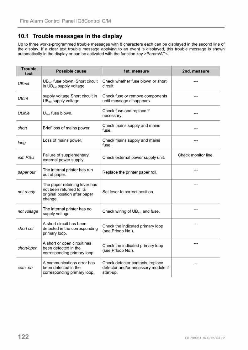
Fire Alarm Control Panel IQ8Control C/M
122 FB 798951.10.GB0 / 03.12
10.1 Trouble messages in the display Up to three works-programmed trouble messages with 8 characters each can be displayed in the second line of the display. If a clear text trouble message applying to an event is displayed, this trouble message is shown automatically in the display or can be activated with the function key >Param/AT<.
Trouble text Possible cause 1st. measure 2nd. measure
UBext UBext fuse blown. Short circuit in UBext supply voltage.
Check whether fuse blown or short circuit.
---
UBint supply voltage Short circuit in UBint supply voltage.
Check fuse or remove components until message disappears.
---
ULinie Uline fuse blown. Check fuse and replace if necessary. ---
short Brief loss of mains power. Check mains supply and mains fuse. ---
long Loss of mains power. Check mains supply and mains fuse.
---
ext. PSU Failure of supplementary external power supply. Check external power supply unit. Check monitor line.
paper out The internal printer has run out of paper. Replace the printer paper roll. ---
not ready
The paper retaining lever has not been returned to its original position after paper change.
Set lever to correct position.
---
not voltage The internal printer has no supply voltage. Check wiring of UBext and fuse. ---
short cct A short circuit has been detected in the corresponding primary loop.
Check the indicated primary loop (see Prloop No.).
---
short/open A short or open circuit has been detected in the corresponding primary loop.
Check the indicated primary loop (see Prloop No.).
---
com. err A communications error has been detected in the corresponding primary loop.
Check detector contacts, replace detector and/or necessary module if start-up.
---

Fire Alarm Control Panel IQ8Control C/M
FB 798951.10.GB0 / 03.12 123
Trouble
text Possible cause 1st. measure 2nd. measure
start-up
An error has been detected when an loop was switched on; normal operation is impossible.
Localise the source with programming software tools 8000 switch on or reconfigure the loop.
---
Detector >
When an loop was switched on, more detectors were found than programmed in the customer data or more detectors were found in an EDD detector zone than programmed in the customer data.
Localise the source with programming software tools 8000, switch on or reconfigure the loop For EDD detector zones, check the number of detectors and reprogram the customer data if necessary.
---
Detector <
When an loop was switched on, fewer detectors were found than programmed in the customer data.
Localise the source with programming software tools 8000, switch on or reconfigure the loop.
---
Topolog. The wiring configuration of this loop cannot be precisely determined.
Localise the source with programming software tools 8000, switch on or reconfigure the loop.
---
Serial No
A detector has been found in the corresponding loop which is not programmed in the customer data.
Have detectors been exchanged and is the error plausible?
If yes, execute the Exchange detector function for this loop to update data.
Line A The 1st ring is inoperable in a redundant essernet® wiring. The 2nd ring is in operation.
Check essernet® wiring Check the essernet® switchover module and replace if necessary.
Line B The 1st ring is inoperable in redundant essernet® wiring. Check essernet® wiring Check switch over module
and replace if necessary.
AD conv.
Fault of the A/D converter card on the Basic module or the A/D converter of the loop module is defective.
Replace Basic module or micro module. ---

Fire Alarm Control Panel IQ8Control C/M
124 FB 798951.10.GB0 / 03.12
Trouble
text Possible cause 1st. measure 2nd. measure
int. det. err A dirty detector was found during an EDD zone test. Clean or replace detector. ---
reset A detector could not be reset during an EDD zone test. Replace detector. ---
no SOC The switch-on control of a detector was impossible during an EDD zone test.
Replace detector. ---
Addr. err. A detector with Address 0 was found during an EDD zone test.
A non-addressable fire detector has been connected in an EDD detector zone.
the address board in the detector base is defective or the illicit address 0 has been selected.
no 24V Loss of line voltage for the indicated module.
Check Uline fuse and replace if necessary. Replace module.
DAC err. Defective D/A converter in the indicated module. Replace module. ---
Request
No valid value can be obtained from an EDD detector zone or a monitored relay
Voltage interference on the line.
Check cable screening and wiring.
Ulinie <
Loop voltage difference, measured from A>B, is too high. Sounder activation is impossible.
Module damaged, loop resistance too high. check loop devices.
WireRes
Loop resistance too high. Sounders are unable to operate with full sound pressure.
Check length of cable, max. 3500 m for IQ8Quad detector with consideration of the load factor.
Check terminals from all loop devices.
Err. 42 V Loss of 42 V DC loop voltage. mains supply not in +42 V DC mode. loop module damaged.
I-MesDef Internal module failure. Module damaged. Sounder damaged.
base The wireless base has been removed from corresponing detector base.
Insert wireless base in detector base ---
Batt<30 Battery below rated voltage Replace battery within 30 days ---
Batt<7 Battery below rated voltage Replace battery within 7 days ---

798951.10.GB0 G 299044
03.2012 G 205129 Technical changes reserved! © 2012 Honeywell International Inc.
GB
Installation Instruction
Fire Alarm Control Panel IQ8Control C/M Options / Special applications

Fire Alarm Control Panel IQ8Control C/M
126 FB 798951.10.GB0 / 03.12
11 Functionality for fire alarm control panels The fire alarm control panel can be programmed to activate door control systems by installing an door control transponder. The esserbus® door control transponder is operated as a bus device on the loop of the IQ8Control fire alarm system. The corresponding detector zones for activating the door controls are programmed in the panel’s customer data. This requires operating system software from Version V3.01 and programming software tools 8000 from Version V1.15 upwards. For further information about door control systems and the door control system functions, refer to technical information about door control systems (Part No. 798840) on the website www.esser-systems.de.
Serial essernet® interface
esserbus®
Hazard management system
esserbus®
door control transponder
Power supplyRelease Button
Contact - Relay 2
Remote indicator
Detector zone for fire Door Control System Application
Magnetic locking device
Graphic layout annunciator panelesserbus®-transponder 32 optocoupler
Fig. 101: Door control system control (schematic diagram) 11.1 Use of the loop module in door control systems
FSA-Koppler808619.10VdS G 206042
1008ESSER
Z-6.5-xxxxVdS
18100
When using analogue loop modules (784382.10 or 804382.10) in door control systems, the label enclosed in the module must be attached onto or in the FACP.
Fig. 102: Example of label with the conformity mark

Fire Alarm Control Panel IQ8Control C/M
FB 798951.10.GB0 / 03.12 127
12 IQ8Wireless IQ8Wireless devices provide the wireless connection of fire alarm detectors and alarm devices to the loop of the Fire alarm system IQ8Control or alternatively a stand-alone wireless control unit for fire alarm panels with conventional detector zone inputs.
30 - 300 m*IQ8ControlIQ8Control 805595.10
max. 32
20 - 200 m*max. 10
805594.10
9 ... 30 V DC
Fig. 103: IQ8Wireless devices (schematic view)
System requirements
• Programming software tools 8000 from Version V1.15 • To operate the IQ8Wireless transponder as a loop device of the Fire Alarm Control System IQ8Control, the
IQ8Control operating system software Version V3.09 is required.
Accessories
Part No. Description 805593.10 IQ8Wireless detector base for automatic Fire detectors series IQ8Quad
(without integrated alarm device) 805594.10 IQ8Wireless gateway 805595.10 IQ8Wireless transponder for wall mounting 805597 4 Lithium batteries (type AA / 3,6V) for power supply 805601.10 IQ8Wireless universal Interface (red), without cover 805602.10 IQ8Wireless universal Interface (white), without cover 805603 IQ8Wireless Mounting frame for Alarm device IQ8Alarm (red + white) 805604 IQ8Wireless Mounting frame for automatic Fire detectors IQ8Quad (white) 805605 Cover for IQ8Wireless Interface 805601 und 805602 (red + white)
For the operation of the intelligent Fire alarm detectors series IQ8Quad with integrated alarm device use Part No. 805602.10 and 805604.
For additional information about the IQ8Wireless devices refer to the corresponding technical manual or visit the Homepage www.esser-systems.de.

Fire Alarm Control Panel IQ8Control C/M
128 FB 798951.10.GB0 / 03.12
12.1 Important battery information Battery information relating to power consumption and batteries (Art. No. 805597) for use in IQ8Wireless RF components
• Insert batteries into the RF devices shortly before initial operation (assigned to the RF transponders)! Unassigned RF devices consume approx. 4 times more power.
• Bear in mind the sufficient remaining field strength! Operation with low field strength causes the power consumption to be somewhat higher. Similar RF devices which were put into operation at the same time may subsequently register low battery voltage (batt. < 30) on the FACP after different running times. The probability of interferences (e.g. caused by electromagnetic pollution or alternating field strength) rises very high relating to the reduced field strength. If the wireless transmission is interrupted and a wireless devices must leave the frequency hopping mode, it is operated in the basic channels until the assigned transponder is able to take this device into the frequency hopping mode again. In this mode the current consumption may increase up to 4 times higher.
• How often a RF transponder has to search for one of its RF devices in the base channel can be determined using the Service PC on the >disturbance< counter in the programming software tools 8000.
• If the 12/24 V DC power supply to a RF transponder should malfunction, the radio operation of the transponder terminates and all the assigned RF devices search in the base channel for this RF transponder. This causes the RF devices’ power consumption to be up to approx. 4 times higher.
• In the case of an alarm, the detectors in the RF devices consume somewhat more power.
• In an uncharged state, the approved batteries (Art. No. 805597) have a very low self-discharge rate (1 % annually @ 25°C ± 10°C). Storage outside this temperature range causes the self-discharge rate to increase. The nominal capacity of the batteries decreases, for example, at low temperatures and is 20-30 % lower during operation near to the freezing point.
• Due to “passivation effects” batteries which are more than 3 years old should no longer be used. Batteries are labelled accordingly. Code 1 (e.g. F.02.277.E)
F = France 02 = produced year 277 = produced day 277th day E = charge
or Code 2 (e.g. 05 049 A 066) 05 = produced year 049 = produced day A 066 = charge
• For initial operation, the batteries are inserted and then charged automatically for a short time and with a very high current. In rare cases, this may cause low battery voltage (batt. < 30) to be immediately displayed on the FACP. Remedy: Activate the RF devices once more using the FACP.
• For functioning devices, the battery voltage is checked approx. every 12 hours automatically and approx. 2 minutes after insertion of the batteries/after activation (detector zone/detector) of a RF device.
• Do not touch the battery poles or contacts of the RF devices with bare fingers! A layer of grease causes transfer resistance to build up between the batteries and contacts. This transfer resistance may lead to the FACP prematurely or incorrectly displaying low battery voltage (batt. < 30).
• Improper storage of the RF devices and batteries may be the cause of such transfer resistance (e.g. due to corrosion). If necessary, clean contacts before inserting the batteries (e.g. with isopropanol solution).
• Only change the batteries as a set (4 items) in order to ensure an equal charge. The registered low battery voltage (batt. < 30) on the FACP always relates to the battery with the smallest capacity.
• For RF devices which register low battery voltage after a long operating time, the malfunction may be repaired during inspection by agitating the batteries used for a short amount of time (a few hours). When the RF device is activated, no “low battery voltage“ message appears. Completely replace the set of batteries for the corresponding RF device!

Fire Alarm Control Panel IQ8Control C/M
FB 798951.10.GB0 / 03.12 129
13 Top hat rail mounting kit (Part No. 788652) In the IQ8Control C / M FACP housing can be installed a top hat rail mounting kit (optional). This mounting kit comprises of a mounting base, a standard 35 mm top hat rail (C-profile mounting), M5 x 30 bolts, M5 x 50 screws and insert nuts. In order to facilitate mounting and removal, the top hat rail is fitted to the mounting base by means of two screws.
Variant 1
With the kit a maximum of two optional module housings (Part No.788603 or 788603.10) can be installed inside the panel housing. The module housing for top hat rail mounting accepts all the format 72 x 65 mm or 82 x 72 mm (W x H) FACP boards e.g. esserbus® transponder, Kit redundant transmission path.
Variant 2
In addition to the module housing, an optical fibre converter (Part No.784763 / 64) with a clip for top hat rail mounting may be installed inside the panel housing.
Mounting
Mounting example – Variant 1: Top hat rail mounting kit with module housings (optional) Components of the Top hat rail mounting kit
4
3
2
1
Fig. 104: Components of the Top hat rail mounting kit
Mounting base for Top hat rail
Fastening screws for Top hat rail
2 x Module housing Part No.788603 / 788603.10 (optional)
Standard Top hat rail, 35 mm

Fire Alarm Control Panel IQ8Control C/M
130 FB 798951.10.GB0 / 03.12
Mounting
Before installation, check whether the required insert nuts are already present inside the FACP. If not, insert the enclosed insert nuts 5 and screw in the bolts 6 . Unscrew and remove the lower right FACP housing screw 7 . Grasp the lower right corner of the front FACP housing half and lift it up carefully from the rear FACP housing half (max. 5mm). Insert the top hat rail mounting kit 8 with the correct orientation in the right rear screw holes of the rear FACP housing half. Replace the front FACP housing half on the rear FACP housing half. Mount the top hat rail mounting kit with the FACP housing screw 7 and enclosed screw 9 .
5
6
7
8
9
Fig. 105: Positioning of the top hat rail mounting kit
Damage to the system Remove all power from the panel before carrying out any installation work (batteries and mains supply). Always check that the connection cables are long enough! Ensure that no cables are pinched or damaged when installing or removing the assembly.
10 Unscrew the left and right fastening screw. Remove one of this screws. 10
11
11 Carefully turn the top hat rail by 90° max. to remove it.
Fig. 106: Mounting/removal of the top hat rail mounting kit
Always check that the connection cables are long enough! Ensure that no cables are pinched or damaged when installing or removing the assembly.

Fire Alarm Control Panel IQ8Control C/M
FB 798951.10.GB0 / 03.12 131
14 esserbus® transponder esserbus® transponders are input/output modules for extending the control panel inputs/outputs. As devices on the loop - the esserbus® - they may be operated jointly in separate detector zones with fire detectors on the esserbus®. It is possible to install up to 32 esserbus® transponders in separate detector zones (separated by zone isolators). Mixing the operation of fire detectors and esserbus® transponders is not permissible within one detector zone. The esserbus® transponders is installed either at special fitting locations or with the top hat rail mounting kit (Part No. 788652) in the Fire Alarm Control Panel, or at decentralised level at any location in a special plastic housing (Part No. 788600 / 788601).
For additional information refer to the technical manual of the esserbus® transponder.
Type Description Part No.
eK-12REL with 12 relay outputs 808610.10
eK-32AE with 32 outputs to drive LED 808611.10
with 4 detector zone inputs and 2 relay outputs 808613.10 eK-4Grp/2Rel
To be operated as standard interface (SST) to control extinguishing systems 808613.30
Alarm Alarm transponder 808623
eK-KOM-LMST Communications transponder for the Extinguishing Control Computer 8010. Installed inside of the Extinguishing Control Computer 8010. 808615
eK-FSA The FSA-transponder for a stand-alone fire door control or as a loop device connected fire alarm system 8000. 808619.10
Third party module Third party module RZT 8000 for an individual connection of automatic and non-automatic fire alarm detectors supplied by other manufacturers
80863X.10
For esserbus® PLus loops with a loop voltage of 42 V it is required to connect the appropriate transponders or devices with the Part No. 80xxx x (refer to Chapter 5.1.2).

Fire Alarm Control Panel IQ8Control C/M
132 FB 798951.10.GB0 / 03.12
15 Extension housing Four different extension housings are available for individual extension of the FACP IQ8Control C/M Part No. Description
789300 Extension housing for batteries Housing complete with battery rear panel, space for two rechargeable batteries with an individual capacity of 12 V / 24 Ah. Neutral front and fastening material for fitting to the central housing.
789301 Extension housing for batteries and GEA 192 MG Housing complete with battery rear panel, space for two rechargeable batteries with an individual capacity of 12 V / 24 Ah. Front panel with built-in group / individual display (GEA) for 192 detector groups and fastening material for fitting to the central housing.
789302 Extension housing for GEA 192 MG Housing complete with standard rear panel for fitting additional subassemblies such as esserbus® transponders. Front panel with built-in group / individual display (GEA) for 192 detector groups and fastening materials for fitting to the central housing.
789303 Extension housing Housing complete with standard rear panel for fitting additional subassemblies such as esserbus® transponders. Neutral front and fastening material for fitting to the central housing.
057633 Mounting plate for master boxes DS 7500 / DS 8800 Mounting plate for master box types DS 7500 / DS 8800 or two esserbus® transponders
Fig. 107: Standard rear panel Battery rear panel
Fig. 108: Mounting plate for master boxes (Part No. 057633)

Fire Alarm Control Panel IQ8Control C/M
FB 798951.10.GB0 / 03.12 133
The extension housing is assembled similar to the central housing. The individual assembly steps are described in the section "Assembling the central housing". The following must also be observed when assembling the extension housing: • The connection pieces between the central and extension housings can be pushed into the housing only
from the rear side due to the door hinge. If an extension housing is fitted at the bottom to an already securely installed central housing, the central housing must be removed from the assembly surface.
• A separate drilling template is available for each of the two housing variants with the standard or battery
rear panel. The drilling template is enclosed in the central unit’s additional pack. • The fastening holes in the mounting surface must be drilled precisely and without offset to the side.
Otherwise, use of the connecting pieces between the two housings is no longer possible in the event of major deviations.
If the extension housing with the battery rear panel is used, please note that depending on the rechargeable batteries used, a significant weight must be supported by the fastening screws of the extension housing. Longer 8 mm flat-head screws should always be used here. Each housing must be separately secured with suitable fastening materials such as screws and dowels. Attachment of the extension housing with fastening only via the connection pieces between the central and extension housing is not permissible.
Rear panel extension example
The standard rear panel may be used in combination with the extension housing (Part No. 789302/03) to install additional components. Holes E and H are provided for mounting the various components. The standard rear panel allows the following extensions: • 6 esserbus® transponders, Part No. 808613.10, 808613.30 (mounting holes E)
or
• 4 esserbus® transponders, Part No. 808610.10 or 808611.10 (holes H) or
• 3 esserbus® transponders, Part No. 808613.10, 808613.30 or 808614.10 (holes E) and 2 esserbus® transponders, Part No. 808610.10 or 808611.10 (holes H)

Fire Alarm Control Panel IQ8Control C/M
134 FB 798951.10.GB0 / 03.12
15.1 Extension housing for two batteries (Part No. 789300 / -01) Up to 2 batteries 12 V / 24 Ah may be placed inside the lower housing part of the IQ8Control M or in the extension housing (Part No. 789300 / -01). The required battery fastener (plastic device) is delivered with the panel equipment.
12
• Place batteries as shown and insert fastener.
• Assemble the additional battery mount and .
Fig. 109: Mechanical battery
Damage to the system! Please note that depending on the rechargeable batteries used, a significant weight must be supported by the fastening screws of the extension housing. It is not permissible to install the rechargeable batteries without these fastening clamps.
Refer Chapter 4.1.3 „Emergency power supply“.

Fire Alarm Control Panel IQ8Control C/M
FB 798951.10.GB0 / 03.12 135
16 Power supply for the built-in printer The internal power supply of the built-in printer is provided by the basic module terminals of the FACP.
switched+12 V UBext.
+UBext.
BR7Printer
Prin
ter
GND
F4+UBext T2A
GND
+UBext.
+12 V DC
ext. power supply
+UBext.
BR7Printer
Prin
ter
GND
F4+UBext T2A
+UBext.
To use an external 12 V DC power supply unit (e.g. Part-No. 805683) open solder jumper BR7 !
Fig. 110: Internal Power supply for the built-in printer Fig. 111: External Power supply for the built-in printer
Accessories fort he built-in printer
Paper for Printer (Part No. 736235) (Part No. 736233 / -34) Dimensions: W = 58 mm, L = 25 m

Fire Alarm Control Panel IQ8Control C/M
136 FB 798951.10.GB0 / 03.12
17 Mounting / Replacing of the Panel front + Printer
17.1 Heat transfer Printer without paper take-up unit (Part No. 7868xx / 7869xx)
Fig. 112: Panel front (Part No. 7868xx1)
Panel front for heat transfer Printer without paper take-up unit. 1) Language identification, e.g. 00=German, 01=English etc.
(refer to catalogue Fire Alarm systems)
Fig. 113: Panel front (Part No. 7869xx1)
Damage to the system
Remove all power from the panel before carrying out any installation work (battery and mains supply voltage).
Mounting / Replacing
1. Remove all power from the panel before carrying out any installation work (batteries and mains supply).
2. Open housing and remove all electrical connections to the mounted control panel.
3. Release mounting brackets and remove the existing operating panel carefully.
4. Insert operating panel and fasten it with the appropriate clamps to the frame. Fit printer in the mounting bracket and fix it with the supplied screws .
5. Connect printer (Ribbon cable and +12 V DC power supply).
6. Release paper clamp of the internal printer and insert paper roll.
7. Lead paper for approx. 5 cm through the opening of the front. Lock paper clamp again.
1
2
Fig. 114: Mounting Panel Front
3Paper clamp, locked
Fig. 115: Insert paper roll

Fire Alarm Control Panel IQ8Control C/M
FB 798951.10.GB0 / 03.12 137
Wiring FACP IQ8Control with Panel front (Part No. 7868xx)
F4+UBext T2A BR7
Printer
Sys
tem
con
nect
or 2
Prin
terGND
X23 Printer
+UBext.
+ -
Basic module
Ribbon cable 1)
GND
switched +12 V ext.
4
Fig. 116: Wiring Printer 1) Ribbon cable, length 50 cm (Part No. 750756) / Ribbon cable, length 120 cm (Part No. 750757)
Customer data programming with tools 8000
The printer must be programmed with the tools 8000 programming software as a >Pixi II Thermal printer< in the panel configuration.
Fig. 117: Programming

Fire Alarm Control Panel IQ8Control C/M
138 FB 798951.10.GB0 / 03.12
Wiring FACP IQ8Control with Panel front (Part No. 7869xx)
IN
Operating panel with 1/4 VGA Display(Part No. 7869XX)
GND
switched +12 V ext.
F4+UBext T2A BR7
PrinterS
yste
m c
onne
ctor
2
Prin
terGND
+UBext.
Basic module + -
X23 Printer X24 MMI
OUT
Ribbon cable 2)Ribbon cable 2)
4
Fig. 118: Wiring Printer 2) Ribbon cable, length 70 cm (Part No. 750720)
Customer data programming with tools 8000
The printer must be programmed with the tools 8000 programming software as a >PIXI II Thermal printer< in the panel configuration. Printer connected to 1/4-VGA-Display
Fig. 119: Programming
Operating 1/4-VGA

Fire Alarm Control Panel IQ8Control C/M
FB 798951.10.GB0 / 03.12 139
17.2 Printer with paper take-up reel (Part No. 7863xx)
Fig. 120: Panel front (Part No. 7863xx1)
Panel front with heat transfer printer with paper take-up reel.
Panel front for heat transfer printer with paper take-up reel (Part No. 7863xx) and printer kit for IQ8Control C / M (Part No. 784792) 1) Language identification, e.g. 00=german, 01=English etc.
(refer to catalogue Fire Alarm systems)
Damage to the system Remove all power from the panel before carrying out any installation work (battery and mains supply voltage).
1
2
1
3
Fig. 121: Mounting / Replacing
Mounting / Replacing
1. Open housing and remove all electrical connections to the mounted control panel (if existing).
2. Remove the printer by releasing the six screws . 3. Insert new printer in the mounting frame and fit screws . 4. Connect printer (Ribbon cable and
+12 V DC power supply) (ref. next Page Fig. 125) 5. Release paper clamps (B+F) of the printer and insert
paper roll. Clamp F must be manually locked again. 6. Release the inserted acrylic plastic sheet at clampers
and insert the new with the blue pad , for covering the paper run.
7. Close housing.
A
B
C
D
EF
G
A Paper take-up reel
B Paper clamp, released
C Paper roll
D Rubber drum
E Printing head
F Head clamp, released
G Board with terminals for the power supply connection and ribbon cable (Centronics)
Fig. 122: Paper roll and paper take-up reel

Fire Alarm Control Panel IQ8Control C/M
140 FB 798951.10.GB0 / 03.12
Wiring FACP IQ8Control
M
+ -
F4+UBext T2A BR7
Printer
Syst
em c
onne
ctor
2
Prin
ter
GND
X23 Printer
+UBext.
Basic moduleIQ8Control
Ribbon cable
GND
switched +12 V ext.
4
Fig. 123: Wiring Printer with paper take-up reel
Customer data programming with tools 8000
The printer must be programmed with the tools 8000 programming software from Version 1.00 or higher as a >Printer with take up reel for Serial 2< in the panel configuration.
Fig. 124: Selecting the printer

Fire Alarm Control Panel IQ8Control C/M
FB 798951.10.GB0 / 03.12 141
18 Fire protection housing F30 The fire protection housing provides the installation of Fire Alarm Control Panels IQ8Control in accordance to the German MLAR and LAR requirements within corresponding ambient conditions. Cabling of fire protection equipment must remain in operation at least for 30 minutes to meet the Fire resistance rating standard F30 for:
• Fire Alarm Control Panels incl. alarm transmission devices
• Systems for alert and notification of Visitors and Employees, if this function is required for alarm conditions Fire alarm systems stipulated by constructional law with esserbus®-PLus alarm devices, may be operated with DiBt approved fire protection housings in accordance to DIN 4102-2. This housing is a part of the systems VDS-approval and ensures the operation of connected alarm devices above the required 30 minutes. Furthermore the fire protection housing complies to the German fire load guideline §40 paragraph 2 of the MBO, whereby a FACP IQ8Control may be operated in escape routes. Other housings and cases do not meet the approval and must not be used for this application.
• At least a single FACP incl. alarm transmission device must be installed in a fire protection housing.
• The front door of the housing is closed in normal operation mode. Due to this the user operation level 1 (in acc. to EN 54-2) is not accessible. Possibly a Fire department operation panel is required by the local authorities.
• The housing fan provides a continuous air exchange and causes an ambient noise of min. 51 dB. Therefore it is recommended not to mount this housings nearby workplaces.
• Consider manufactures installation manuals of the housing to mount the FACP!
• Warranty is detailed in manufacturers information, company Priorit AG
Housing type versions
788033 Fire protection housing F30 R, wall mounting 788034 Fire protection housing F30 L, wall mounting 788035 Fire protection housing F30 R, standing 788036 Fire protection housing F30 L, standing
Refer to product catalog fire systems for additional information.

Novar GmbH a Honeywell Company
Dieselstraße 2, D-41469 Neuss Telefon: +49 (0) 21 37 / 17-0 Verwaltung
Internet: www.esser-systems.de +49 (0) 21 37 / 17-600 KBC
E-Mail: [email protected] Telefax: +49 (0) 21 37 / 17-286