Installation guidelines for LPG systems by AC S.A. · STAG Service Point compliance with the rules...
16
1 Installation guidelines for LPG systems by AC S.A.
Transcript of Installation guidelines for LPG systems by AC S.A. · STAG Service Point compliance with the rules...
1
Installation guidelines for LPG systems by AC S.A.

2
Garages approved as STAG Authorized Service Points must follow the guidelines for automotive autogas installation presented in the “Installation guidelines for LPG systems by AC S.A.”.
Adherence to the guidelines by our Partner Service Points (PSP) ensures the consistently high quality of customer service.
STAG Service Point compliance with the rules presented in the “Installation guidelines for LPG systems by AC S.A.” is controlled by the Regional Technical and Sales Consultants and the Market Manager of AC Company.
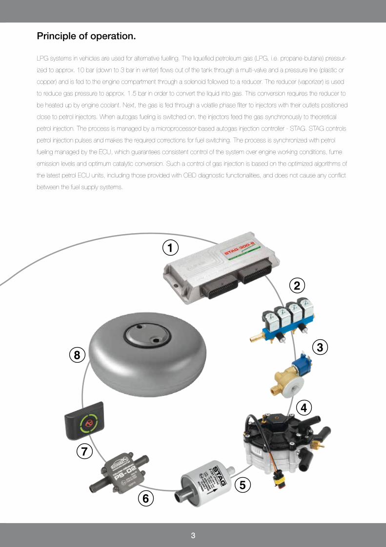
1 controller
2 gas injectors
3 solenoid valve
4 reduktor
5 gas filter
6 pressure sensor
7 pressure switch
8 tank
3
LPG systems in vehicles are used for alternative fuelling. The liquefied petroleum gas (LPG, i.e. propane-butane) pressur-
ized to approx. 10 bar (down to 3 bar in winter) flows out of the tank through a multi-valve and a pressure line (plastic or
copper) and is fed to the engine compartment through a solenoid followed to a reducer. The reducer (vaporizer) is used
to reduce gas pressure to approx. 1.5 bar in order to convert the liquid into gas. This conversion requires the reducer to
be heated up by engine coolant. Next, the gas is fed through a volatile phase filter to injectors with their outlets positioned
close to petrol injectors. When autogas fueling is switched on, the injectors feed the gas synchronously to theoretical
petrol injection. The process is managed by a microprocessor-based autogas injection controller - STAG. STAG controls
petrol injection pulses and makes the required corrections for fuel switching. The process is synchronized with petrol
fueling managed by the ECU, which guarantees consistent control of the system over engine working conditions, fume
emission levels and optimum catalytic conversion. Such a control of gas injection is based on the optimized algorithms of
the latest petrol ECU units, including those provided with OBD diagnostic functionalities, and does not cause any conflict
between the fuel supply systems.
Principle of operation.
1
2
3
4
56
7
8
4
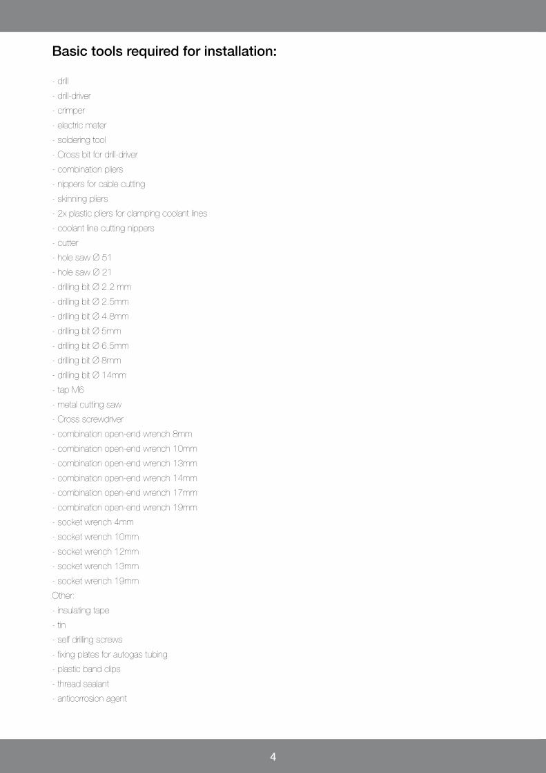
- drill
- drill-driver
- crimper
- electric meter
- soldering tool
- Cross bit for drill-driver
- combination pliers
- nippers for cable cutting
- skinning pliers
- 2x plastic pliers for clamping coolant lines
- coolant line cutting nippers
- cutter
- hole saw Ø 51
- hole saw Ø 21
- drilling bit Ø 2.2 mm
- drilling bit Ø 2.5mm
- drilling bit Ø 4.8mm
- drilling bit Ø 5mm
- drilling bit Ø 6.5mm
- drilling bit Ø 8mm
- drilling bit Ø 14mm
- tap M6
- metal cutting saw
- Cross screwdriver
- combination open-end wrench 8mm
- combination open-end wrench 10mm
- combination open-end wrench 13mm
- combination open-end wrench 14mm
- combination open-end wrench 17mm
- combination open-end wrench 19mm
- socket wrench 4mm
- socket wrench 10mm
- socket wrench 12mm
- socket wrench 13mm
- socket wrench 19mm
Other:
- insulating tape
- tin
- self drilling screws
- fixing plates for autogas tubing
- plastic band clips
- thread sealant
- anticorrosion agent
Basic tools required for installation:

5
Acceptance of customer vehicle for autogas installation.
Ensure that the vehicle is technically sound before starting installation.
Vehicles with engine faults will never operate correctly when fueled with autogas.
All defects causing engine interference must be eliminated before the installation.
External inspection and checking the technical condition of the vehicle.
Verification of the number of cylinders and engine power.
Selection of positions for the petrol/gas switch and filling valve.
Filling in the protocol of vehicle acceptance for installation
with the customer.
Diagnostic of correct engine operation with petrol fueling:
Checking petrol corrections with a diagnostic tool – the values should be
close to “0”.
Checking oxygen sensor operation.
Reviewing error codes recorded by the ECU for petrol.
Fume emission measurement using an exhaust tester (applies to older
models).
In order to select the best autogas system and ensure its full functionality, as well as to protect the interests of our
service points and customers, the installer should perform the following initial procedures:
6
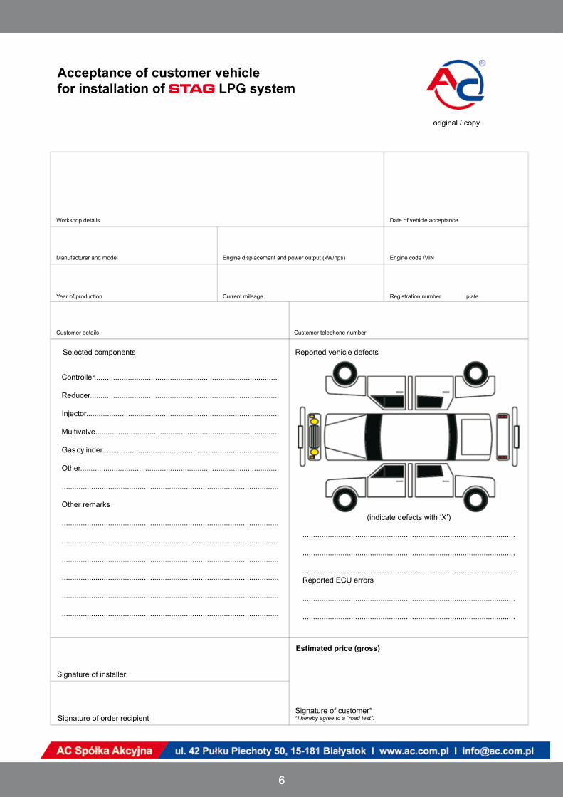
Acceptance of customer vehicle for installation of STAG LPG system
original / copy
Date of vehicle acceptanceWorkshop details
Manufacturer and model Engine displacement and power output (kW/hps) Engine code /VIN
Year of production Current mileage Registration number plate
Customer details Customer telephone number
Selected components
Controller....................................................................................... Reducer..........................................................................................
Injector............................................................................................
Multivalve........................................................................................
Gas cylinder....................................................................................
Other...............................................................................................
.......................................................................................................
Other remarks
.......................................................................................................
.......................................................................................................
.......................................................................................................
.......................................................................................................
.......................................................................................................
.......................................................................................................
Signature of installer
Signature of order recipient
Reported ECU errors
.....................................................................................................
.....................................................................................................
Estimated price (gross)
Reported vehicle defects
(indicate defects with ‘X’)
.....................................................................................................
.....................................................................................................
.....................................................................................................
Signature of customer**I hereby agree to a “road test”.
7
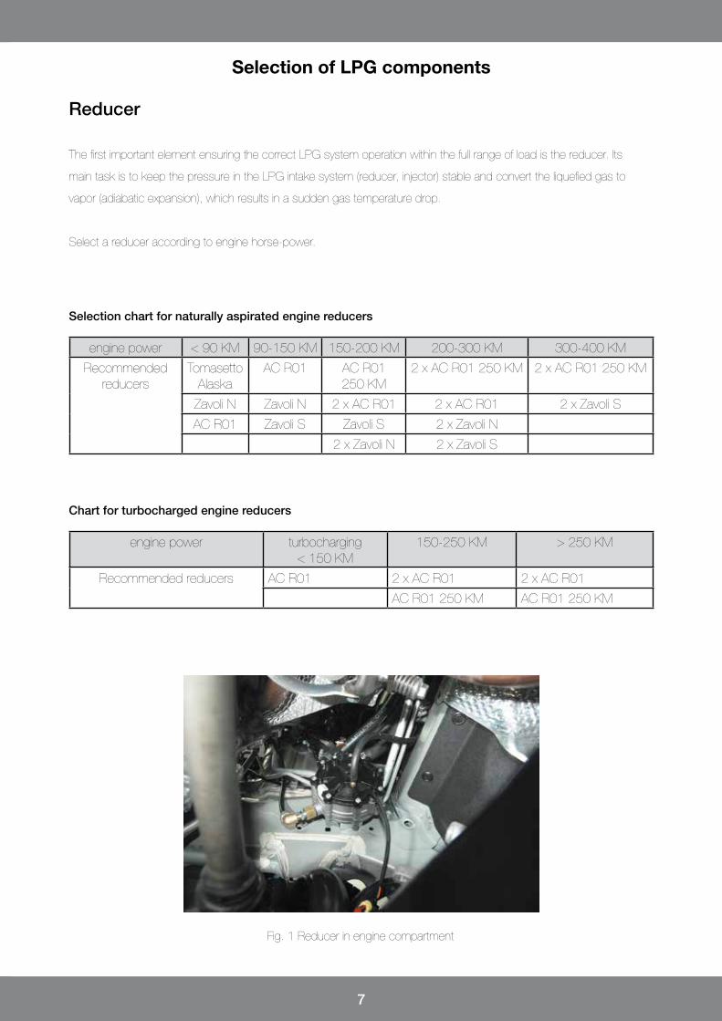
Selection of LPG components
Fig. 1 Reducer in engine compartment
Reducer
The first important element ensuring the correct LPG system operation within the full range of load is the reducer. Its
main task is to keep the pressure in the LPG intake system (reducer, injector) stable and convert the liquefied gas to
vapor (adiabatic expansion), which results in a sudden gas temperature drop.
Select a reducer according to engine horse-power.
engine power < 90 KM 90-150 KM 150-200 KM 200-300 KM 300-400 KM
Recommended reducers
Tomasetto Alaska
AC R01 AC R01 250 KM
2 x AC R01 250 KM 2 x AC R01 250 KM
Zavoli N Zavoli N 2 x AC R01 2 x AC R01 2 x Zavoli S
AC R01 Zavoli S Zavoli S 2 x Zavoli N
2 x Zavoli N 2 x Zavoli S
Selection chart for naturally aspirated engine reducers
engine power turbocharging < 150 KM
150-250 KM > 250 KM
Recommended reducers AC R01 2 x AC R01 2 x AC R01
AC R01 250 KM AC R01 250 KM
Chart for turbocharged engine reducers
8
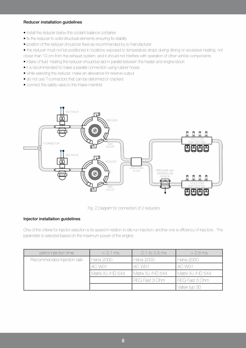
• install the reducer below the coolant balance container• fix the reducer to solid structural elements ensuring its stability• position of the reducer should be fixed as recommended by is manufacturer• the reducer must not be positioned in locations exposed to temperature drops during driving or excessive heating, not closer than 10 cm from the exhaust system, and it should not interfere with operation of other vehicle components• intake of fluid heating the reducer should be laid in parallel between the heater and engine block• it is recommended to make a parallel connection using rubber hoses• while selecting the reducer, make an allowance for reserve output• do not use T-connectors that can be deformed or cracked• connect the safety valve to the intake manifold
Fig. 2 Diagram for connection of 2 reducers
Reducer installation guidelines
Injector installation guidelines
One of the criteria for injector selection is its speed in relation to idle run injection; another one is efficiency of injectors . The parameter is selected based on the maximum power of the engine.
petrol injection time < 2,1 ms 2,1 to 2,5 ms > 2,6 ms
Recommended injection rails Hana 2000 Hana 2000 Hana 2000
AC W01 AC W01 AC W01
Matrix XJ /HD 544 Matrix XJ /HD 544 Matrix XJ /HD 544
REG Fast 3 Ohm REG Fast 3 Ohm
Valtek typ 30
MULTIVALVE
MULTIVALVE
T-CONNECTOR
REDUCER
REDUCER
LPG or CNGFILTER
GASOUTLET
GASOUTLET
PRESSURE AND TEMPERATURE
SENSOR
LPG or CNGINJECTION RAIL
LPG or CNGINJECTION RAIL

9
Fig. 3 Installation of injectors in the engine compartment Fig. 4 Line secured with a band clip
Select the nozzle diameter depending on the power per cylinder.The table below presents the selection of nozzles based on the example of Valtek rail, type 30 3Ω.
Injection nozzle diameter [mm](pressure 1 bar, Valtek rail 30 3Ω)
Power per cylinder [hps] / [kW]
1,8 - 2 16 - 22 / 12 - 16
2,1 - 2,3 23 - 29 / 17 - 22
2,4 - 2,6 30 - 35 / 23 - 26
2,7 - 2,9 36 - 41 / 27 - 31
3 42 - 45 / 32 - 34
Selection of nozzles for Valtek 30 3Ω rail
Maximum injector output per cylinder at 1 bar
Valtek typ 30 40 hps / cylinder
AC W01 40 hps / cylinder
AC W01 BFC 55 hps / cylinderHana 2000 type A+/A/B/C 50 / 42 / 32 / 25 hps / cylinder
Rail 3Ω 50 hps / cylinder
Magic Jet 50 hps / cylinder
REG Fast 3Ω 40 hps / cylinder
• injector nozzles should be positioned downwards (where possible),• injector fixing must be rigid; use fixing plates for attaching elements to solid parts of the engine and rubber vibration at-tenuators,• if two injectors are used, the rails should be connected with each other using a rubber hose in order to equalize rail pres-sures,• lines between the rail and manifold fitting must be equal in length and as short as possible, with the lowest possible di-ameter (recommended 4 mm),• the lines should not be kinked, pressed or obstructed,• secure hoses installed on the nozzles using band clips.
Injection rail installation guidelines
10
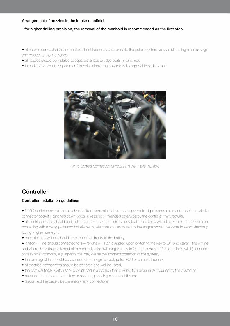
Fig. 5 Correct connection of nozzles in the intake manifold
• all nozzles connected to the manifold should be located as close to the petrol injectors as possible, using a similar angle with respect to the inlet valves,• all nozzles should be installed at equal distances to valve seats (in one line),• threads of nozzles in tapped manifold holes should be covered with a special thread sealant.
Arrangement of nozzles in the intake manifold
- for higher drilling precision, the removal of the manifold is recommended as the first step.
ControllerController installation guidelines
• STAG controller should be attached to fixed elements that are not exposed to high temperatures and moisture, with its connector socket positioned downwards, unless recommended otherwise by the controller manufacturer,• all electrical cables should be insulated and laid so that there is no risk of interference with other vehicle components or contacting with moving parts and hot elements; electrical cables routed to the engine should be loose to avoid stretching during engine operation,• controller supply lines should be connected directly to the battery,• ignition (+) line should connected to a wire where +12V is applied upon switching the key to ON and starting the engine and where the voltage is turned off immediately after switching the key to OFF (preferably +12V at the key switch), connec-tions in other locations, e.g. ignition coil, may cause the incorrect operation of the system,• the rpm signal line should be connected to the ignition coil, petrol ECU or camshaft sensor,• all electrical connections should be soldered and well insulated,• the petrol/autogas switch should be placed in a position that is visible to a driver or as required by the customer,• connect the (-) line to the battery or another grounding element of the car,• disconnect the battery before making any connections.
11
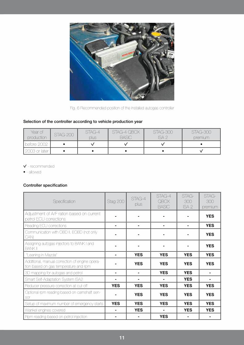
Fig. 6 Recommended position of the installed autogas controller
Year of production
STAG-200STAG-4
plusSTAG-4 QBOX
BASICSTAG-300
ISA 2STAG-300 premium
before 2002 • •
2003 or later • • • •
Selection of the controller according to vehicle production year
Specification Stag 200STAG-4
plus
STAG-4 QBOX BASIC
STAG-300 ISA 2
STAG-300
premium
Adjustment of A/F ration based on current petrol ECU corrections
- - - - YES
Reading ECU corrections - - - - YESCommunication with OBD II, EOBD (not only CAN)
- - - - YES
Assigning autogas injectors to BANK I and BANK II
- - - - YES
“Leaning in Mazda” - YES YES YES YESAdditional, manual correction of engine opera-tion based on gas temperature and rpm
- YES YES YES YES
3D mapping for autogas and petrol - - YES YES -Smart Self-Adaptation System ISA2 - - - YES -Reducer pressure correction at cut-off YES YES YES YES YESOptional rpm reading based on camshaft sen-sor
- YES YES YES YES
Setup of maximum number of emergency starts YES YES YES YES YESWankel engines covered - YES - YES YESRpm reading based on petrol injection - - YES - -
Controller specification
- recommended• - allowed
12
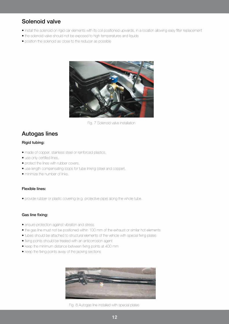
Fig. 7 Solenoid valve installation
Fig. 8 Autogas line installed with special plates
Solenoid valve• install the solenoid on rigid car elements with its coil positioned upwards, in a location allowing easy filter replacement• the solenoid valve should not be exposed to high temperatures and liquids• position the solenoid as close to the reducer as possible
• made of copper, stainless steel or reinforced plastics,• use only certified lines,• protect the lines with rubber covers,• use length compensating loops for tube linking (steel and copper),• minimize the number of links.
Rigid tubing:
Autogas lines
• provide rubber or plastic covering (e.g. protective pipe) along the whole tube.
Flexible lines:
• ensure protection against vibration and stress• the gas line must not be positioned within 100 mm of the exhaust or similar hot elements• tubes should be attached to structural elements of the vehicle with special fixing plates • fixing points should be treated with an anticorrosion agent• keep the minimum distance between fixing points at 400 mm• keep the fixing points away of the jacking sections
Gas line fixing:
13
Fig. 10 Cylindrical tank behind the backseat
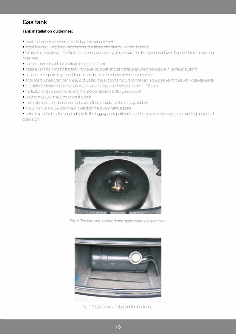
Fig. 9 Toroidal tank installed in the spare wheel compartment
• position the tank as recommended by the manufacturer• install the tank using fixed attachments or a frame and straps included in the kit• for external installation, the tank, its connections and fixtures should not be positioned lower than 200 mm above the base level• chassis bolts should not protrude more than 2 cm• install a ventilation line for the tank, however, its outlet should not face any heat sources (e.g. exhaust system)• all used metal parts (e.g. for drilling) should be protected with anticorrosion coats• if the spare wheel chamber is made of plastic, the support structure for the tank should be reinforced with metal elements• the distance between the cylindrical tank and the backseat should be min. 100 mm,• multivalve angle should be 30 degrees perpendicularly to the ground level• provide moisture insulation under the tank• metal elements should not contact each other; provide insulators, e.g. rubber• the tank must not be positioned lower than the lowest vehicle parts• cylindrical tanks installed longitudinally to the luggage compartment must be provided with barriers preventing accidental dislocation
Tank installation guidelines:
Gas tank

14
Fig. 11 Tank fixing
Fig. 12 Fixing the volatile phase filter
Fig. 13 Vacuum from the manifold downstream the throttle
• position the volatile phase filter between the reducer and the measuring port (or gas pressure sensor), attach it to the bodywork according the direction of gas flow, away of high temperature exposure• filters provided with a settling chamber should have the chamber directing downwards
Volatile phase filter installation guidelines
Volatile phase filter
• the vacuum is taken from the intake manifold, directly after the throttle within the shared section of the manifold• do not use the vacuum from other sections of the manifold or from the servo valve• the vacuum line should be as short as possible
Manifold vacuum
15
• fill in the tank• check system tightness by connecting the battery (+) to the blue wire of the solenoid (do not connect (-), as it is supplied by the STAG controller) • check filling tank tightness • check the tightness of the multivalve and tank connection • check tightness of all Faro type gas line connections (liquefied gas lines) • check tightness of all lines supplying gas between the reducer and injection rail• having checked the gas tightness, verify if coolant connections are not leaking (the best way is warm the engine up first to increase the coolant pressure, which makes the check much more reliable)• check if all parameters read by the autogas controller are correct• correct readings for petrol injection pulses• correct readings for engine rpm• correct readings for gas and reducer temperatures• correct readings for gas pressure• correct readings for intake manifold vacuum• correct readings for oxygen sensor parameters• if all mentioned parameters comply with the specifications (real values), perform auto-calibration followed by a test drive adjustments
After installation of the autogas system:
Autogas system adjustment
Having completed installation and STAG system adjustments, fill in the required documentation:
• list all installed components (reducer/reducers, injection rail, nozzle diameter on the injection rail)
• download oscilloscope files
• record the applied settings
• take photos with exact locations of installed components:
- reducer/reducers
- injection rail
- tank fixing
- general view of the engine compartment
- STAG controller
- switch inside the cabin
Installation documentation

16
AC Spółka Akcyjnaul. 42 Pułku Piechoty 50, 15-181 Białystok, Polandtel. +48 85 743 81 00, fax. +48 85 653 93 83www.ac.com.pl I [email protected]
View our offer.