Installation Guide Panic Hardware for Exit Doors · By following the simple steps in this...
23
IMPORTANT INFORMATION By following the simple steps in this installation guide, Arm-A-Dor ™ . Arm-A-Dor will be successfully installed in approximately one to two hours depending on model type and options. A drill template is provided to ensure Arm-A-Dor is installed correctly. Failure to use installation guide and drill template can cause Arm-A-Dor to operate improperly and/or cause excessive wear which will void 5 year warranty. A Low Profile Kit is required when installing Arm-A-Dor on door with door jamb depths greater than 6 3/4”. Installation Guide Panic Hardware for Exit Doors UL 10B Fire Rated New York City Building Code Approved Dade County Product Approved California Building Code Approved Corporate Headquarters 6161 East 75th Street Indianapolis, IN 46250 USA Technical Support: 800-392-5209 www.precisionhardware.com Note STOP Symbols in this installation guide. If conditions are not as required, DO NOT PROCEED with installation. 630-328 REV. 04/17
Transcript of Installation Guide Panic Hardware for Exit Doors · By following the simple steps in this...
IMPORTANT INFORMATION By following the simple steps in this installation guide, Arm-A-Dor™. Arm-A-Dor will be successfully installedin approximately one to two hours depending on model type and options. A drill template is provided to ensure Arm-A-Dor is installed correctly. Failure to use installation guide and drill template can cause Arm-A-Dor tooperate improperly and/or cause excessive wear which will void 5 year warranty. A Low Profile Kit is required when installing Arm-A-Dor on door with door jamb depths greater than 6 3/4”.
Installation GuidePanic Hardware for Exit Doors
UL 10B Fire RatedNew York City Building Code ApprovedDade County Product ApprovedCalifornia Building Code Approved
Corporate Headquarters 6161 East 75th Street
Indianapolis, IN 46250 USA
Technical Support: 800-392-5209 www.precisionhardware.com
Note STOP Symbols in this installation guide.
If conditions are not as required,DO NOT PROCEED
with installation.
630-328 REV. 04/17
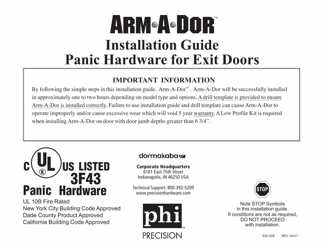
Completed Installations
ALARM
ALARM
OFFON
ALARM
ALARM
OFFON
STANDARD
3 Foot
LOW PROFILEJambs greater than 6 3/4”
(Low profile kit required A104-001)
STRIKE
SIDE
STRIKE
SIDE
HINGE
SIDE
HINGE
SIDE
LN4055 10/3/05 4:28 PM Page 3
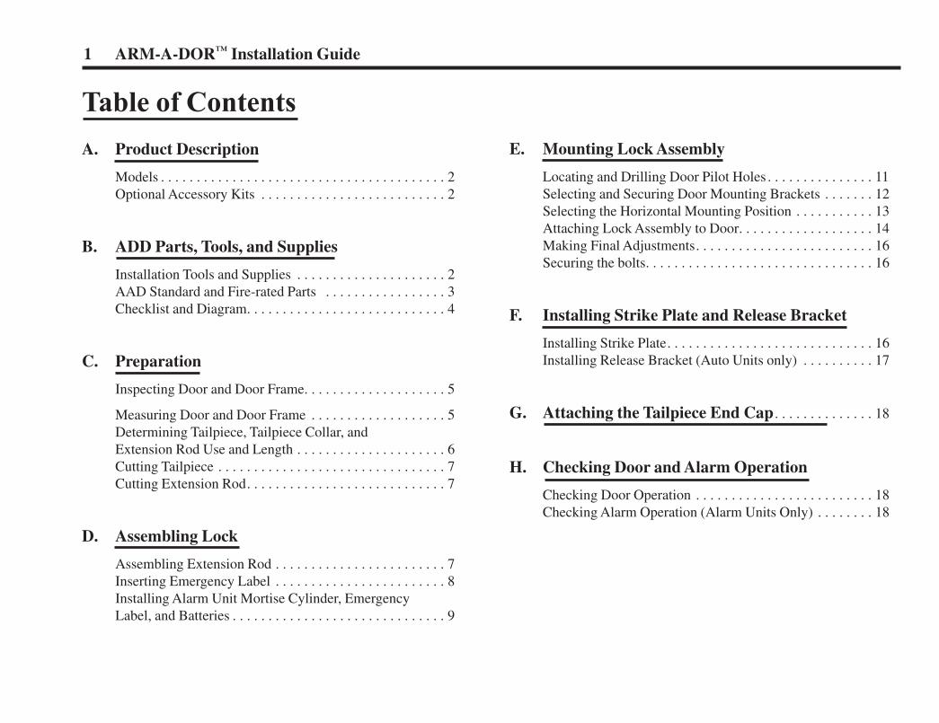
Table of Contents
A. Product Description
Models . . . . . . . . . . . . . . . . . . . . . . . . . . . . . . . . . . . . . . . . 2Optional Accessory Kits . . . . . . . . . . . . . . . . . . . . . . . . . . 2
B. ADD Parts, Tools, and Supplies
Installation Tools and Supplies . . . . . . . . . . . . . . . . . . . . . 2AAD Standard and Fire-rated Parts . . . . . . . . . . . . . . . . . 3Checklist and Diagram. . . . . . . . . . . . . . . . . . . . . . . . . . . . 4
C. Preparation
Inspecting Door and Door Frame. . . . . . . . . . . . . . . . . . . . 5
Measuring Door and Door Frame . . . . . . . . . . . . . . . . . . . 5Determining Tailpiece, Tailpiece Collar, and Extension Rod Use and Length . . . . . . . . . . . . . . . . . . . . . 6Cutting Tailpiece . . . . . . . . . . . . . . . . . . . . . . . . . . . . . . . . 7 Cutting Extension Rod. . . . . . . . . . . . . . . . . . . . . . . . . . . . 7
D. Assembling Lock
Assembling Extension Rod . . . . . . . . . . . . . . . . . . . . . . . . 7Inserting Emergency Label . . . . . . . . . . . . . . . . . . . . . . . . 8Installing Alarm Unit Mortise Cylinder, EmergencyLabel, and Batteries . . . . . . . . . . . . . . . . . . . . . . . . . . . . . . 9
E. Mounting Lock Assembly
Locating and Drilling Door Pilot Holes . . . . . . . . . . . . . . . 11Selecting and Securing Door Mounting Brackets . . . . . . . 12Selecting the Horizontal Mounting Position . . . . . . . . . . . 13Attaching Lock Assembly to Door. . . . . . . . . . . . . . . . . . . 14Making Final Adjustments. . . . . . . . . . . . . . . . . . . . . . . . . 16Securing the bolts. . . . . . . . . . . . . . . . . . . . . . . . . . . . . . . . 16
F. Installing Strike Plate and Release Bracket
Installing Strike Plate. . . . . . . . . . . . . . . . . . . . . . . . . . . . . 16Installing Release Bracket (Auto Units only) . . . . . . . . . . 17
G. Attaching the Tailpiece End Cap . . . . . . . . . . . . . . 18
H. Checking Door and Alarm Operation
Checking Door Operation . . . . . . . . . . . . . . . . . . . . . . . . . 18Checking Alarm Operation (Alarm Units Only) . . . . . . . . 18
1 ARM-A-DOR™ Installation Guide
LN4055 10/3/05 4:28 PM Page 4
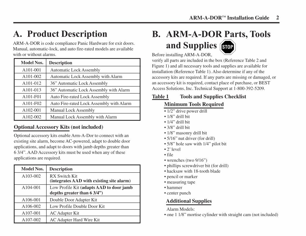
B. ARM-A-DOR Parts, Toolsand Supplies
Before installing ARM-A-DOR, verify all parts are included in the box (Reference Table 2 andFigure 1) and all necessary tools and supplies are available forinstallation (Reference Table 1). Also determine if any of theaccessory kits are required. If any parts are missing or damaged, oran accessory kit is required, contact place of purchase, or BEST Access Solutions, Inc. Technical Support at 1-800-392-5209.
Table 1 Tools and Supplies ChecklistMinimum Tools Required• 1/2” drive power drill• 1/8” drill bit• 1/4” drill bit• 3/8” drill bit• 1/8” masonry drill bit• 5/16” nut driver (for drill)• 5/8” hole saw with 1/4” pilot bit• 2’ level• file• wrenches (two 9/16”)• phillips screwdriver bit (for drill)• hacksaw with 18-tooth blade• pencil or marker• measuring tape• hammer• center punch
Additional Supplies
Alarm Models:• one 1 1/8” mortise cylinder with straight cam (not included)
A. Product DescriptionARM-A-DOR is code compliance Panic Hardware for exit doors.Manual, automatic-lock, and auto fire-rated models are availablewith or without alarms.
A103-002 RX Switch Kit(integrates AAD with existing site alarm)
A104-001 Low Profile Kit (adapts AAD to door jamb depths greater than 6 3/4”)
A106-001 Double Door Adapter KitA106-002 Low Profile Double Door Kit
A107-001 AC Adapter Kit
A107-002 AC Adapter Hard Wire Kit
Optional Accessory Kits (not included)
Optional accessory kits enable Arm-A-Dor to connect with anexisting site alarm, become AC-powered, adapt to double doorapplications, and adapt to doors with jamb depths greater than 6 3/4”. AAD Accessory kits must be used when any of these applications are required.
A101-001 Automatic Lock AssemblyA101-002 Automatic Lock Assembly with Alarm
A101-012 36” Automatic Lock Assembly
A101-013 36” Automatic Lock Assembly with Alarm
A101-F01 Auto Fire-rated Lock Assembly
A101-F02 Auto Fire-rated Lock Assembly with Alarm
A102-001 Manual Lock Assembly
A102-002 Manual Lock Assembly with Alarm
2ARM-A-DOR™ Installation Guide
Model Nos. Description
Model Nos. Description
LN4055 10/3/05 4:28 PM Page 5
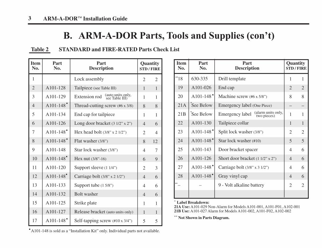
* Label Breakdown:21A Use: A101-029 Non-Alarm for Models A101-001, A101-F01, A102-00121B Use: A101-027 Alarm for Models A101-002, A101-F02, A102-002** Not Shown in Parts Diagram.
1 Lock assembly
2 A101-128 Tailpiece (see Table III)
3 A101-129 Extension rod
4 A101-148 Thread-cutting screw (#6 x 3/8)
5 A101-134 End cap for tailpiece
6 A101-126 Long door bracket (3 1/2” x 2”)
7 A101-148 Hex head bolt (3/8” x 2 1/2”)
8 A101-148 Flat washer (3/8”)
9 A101-148 Star lock washer (3/8”)
10 A101-148 Hex nut (3/8”-16)
11 A101-120 Support sleeve (1 1/4”)
12 A101-148 Carriage bolt (3/8” x 2 1/2”)
13 A101-133 Support tube (1 5/8”)
14 A101-132 Bolt washer
15 A101-125 Strike plate
16 A101-127 Release bracket (auto units only)
17 A101-148 Self-tapping screw (#10 x 3/4”)
2 2
1 1
1 1
8 8
1 1
4 6
2 4
8 12
4 7
6 9
2 3
4 6
4 6
4 6
1 1
1 1
5 5
1 1
2 2
8 8
– –
1 1
1 1
2 2
5 5
4 6
4 6
4 6
4 6
2 2
18 630-335 Drill template
19 A101-026 End cap
20 A101-148 Machine screw (#6 x 5/8”)
21A See Below Emergency label (One Piece)
21B See Below Emergency label
22 A101-130 Tailpiece collar
23 A101-148 Split lock washer (3/8”)
24 A101-148 Star lock washer (#10)
25 A101-143 Door bracket spacer
26 A101-126 Short door bracket (1 1/2” x 2”)
27 A101-148 Carriage bolt (3/8” x 3 1/2”)
28 A101-148 Gray vinyl cap
– – 9 - Volt alkaline battery
B. ARM-A-DOR Parts, Tools and Supplies (con’t)Table 2 STANDARD and FIRE-RATED Parts Check List
Item Part Part No. No. Description
QuantitySTD / FIRE
3 ARM-A-DOR™ Installation Guide
Item Part Part No. No. Description
QuantitySTD / FIRE
*
*
**
**
(auto units only, see Table III)
(alarm units only,two pieces)
•
•
•
•
•
•
•
•
•
•
•
•
A101-148 is sold as a “Installation Kit” only. Individual parts not available.
LN4055 10/3/05 4:28 PM Page 6
ALARM
ALARM
OFFON
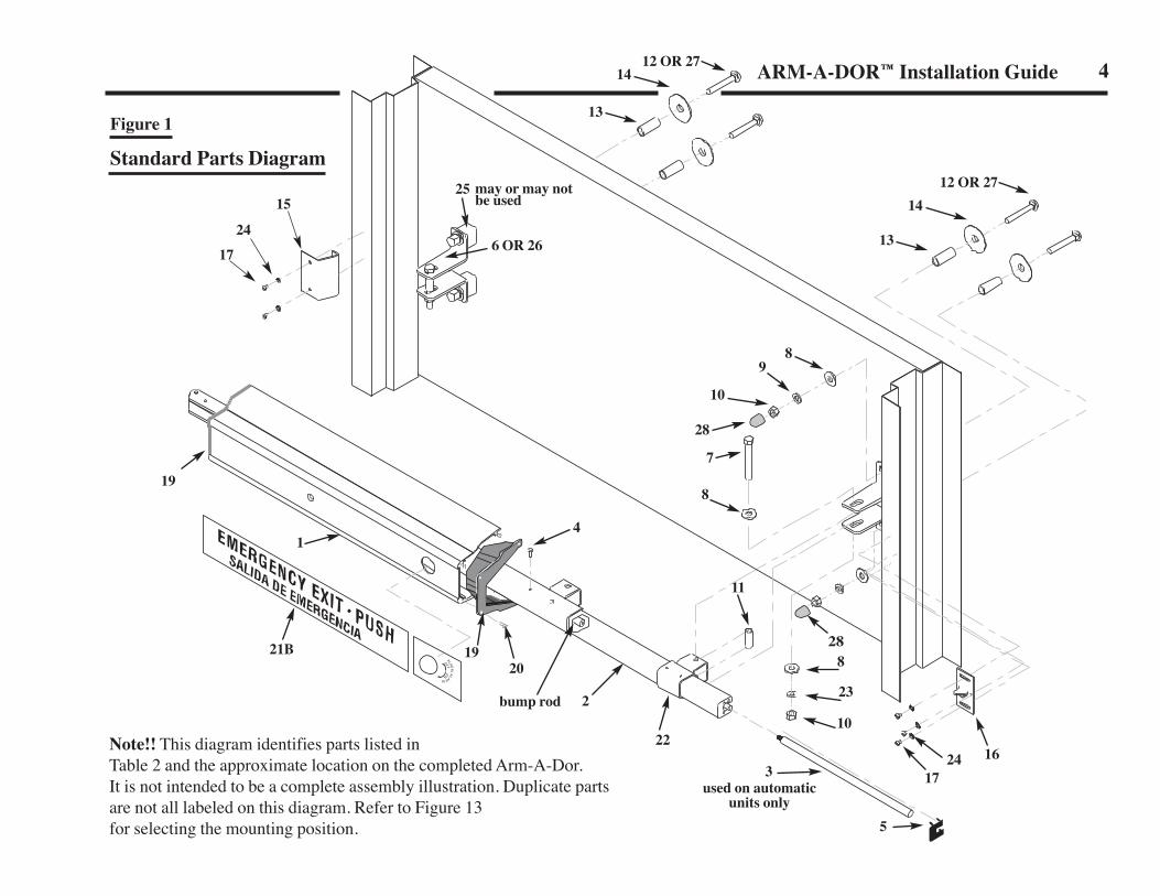
Note!! This diagram identifies parts listed in Table 2 and the approximate location on the completed Arm-A-Dor. It is not intended to be a complete assembly illustration. Duplicate partsare not all labeled on this diagram. Refer to Figure 13 for selecting the mounting position.
Figure 1
Standard Parts Diagram
4ARM-A-DOR™ Installation Guide
25 may or may notbe used
1412 OR 27
15
24
17 6 OR 26
14
13
13
10
28
7
8
828
23
10
173
5
22
2
20
bump rod
used on automaticunits only
21B
19
1
19
1624
11
4
98
12 OR 27
C. PreparationInspecting Door and Door Frame
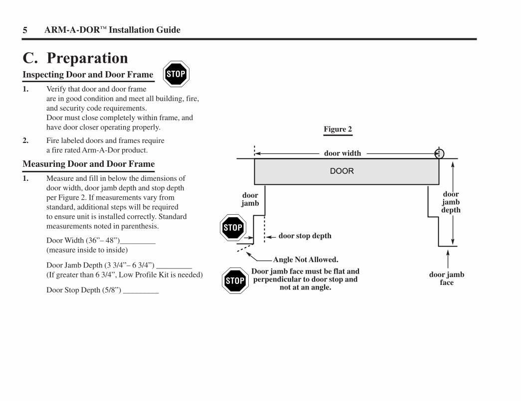
1. Verify that door and door frameare in good condition and meet all building, fire,and security code requirements.Door must close completely within frame, andhave door closer operating properly.
2. Fire labeled doors and frames requirea fire rated Arm-A-Dor product.
Measuring Door and Door Frame
1. Measure and fill in below the dimensions ofdoor width, door jamb depth and stop depthper Figure 2. If measurements vary fromstandard, additional steps will be requiredto ensure unit is installed correctly. Standardmeasurements noted in parenthesis.
Door Width (36”– 48”)_________(measure inside to inside)
Door Jamb Depth (3 3/4”– 6 3/4”) _________(If greater than 6 3/4”, Low Profile Kit is needed)
Door Stop Depth (5/8”) _________
Figure 2
DOOR
5 ARM-A-DOR™ Installation Guide
doorjambdepth
door stop depth
door jambface
doorjamb
door width
Angle Not Allowed.
Door jamb face must be flat andperpendicular to door stop and
not at an angle.
LN4055 10/3/05 4:28 PM Page 8
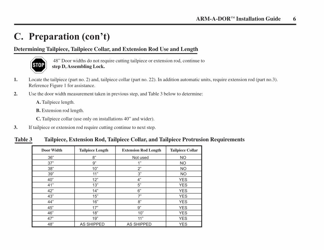
Table 3 Tailpiece, Extension Rod, Tailpiece Collar, and Tailpiece Protrusion Requirements
48” Door widths do not require cutting tailpiece or extension rod, continue to step D, Assembling Lock.
C. Preparation (con’t)Determining Tailpiece, Tailpiece Collar, and Extension Rod Use and Length
1. Locate the tailpiece (part no. 2) and, tailpiece collar (part no. 22). In addition automatic units, require extension rod (part no.3).Reference Figure 1 for assistance.
2. Use the door width measurement taken in previous step, and Table 3 below to determine:
A. Tailpiece length.
B. Extension rod length.
C. Tailpiece collar (use only on installations 40” and wider).
3. If tailpiece or extension rod require cutting continue to next step.
36” 8” Not used NO37” 9” 1” NO38” 10” 2” NO39” 11” 3” NO40” 12” 4” YES41” 13” 5” YES42” 14” 6” YES43” 15” 7” YES44” 16” 8” YES45” 17” 9” YES46” 18” 10” YES47” 19” 11” YES48” AS SHIPPED AS SHIPPED YES
Door Width Tailpiece Length Extension Rod Length Tailpiece Collar
6ARM-A-DOR™ Installation Guide
LN4055 10/3/05 4:28 PM Page 9
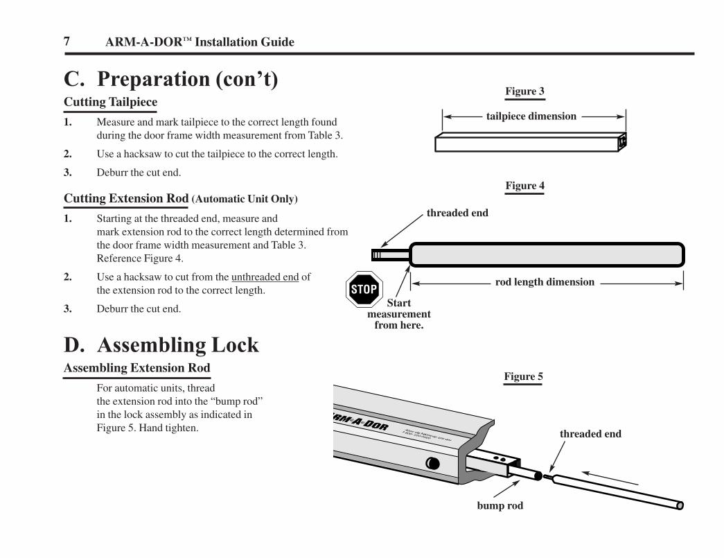
C. Preparation (con’t)Cutting Tailpiece
1. Measure and mark tailpiece to the correct length foundduring the door frame width measurement from Table 3.
2. Use a hacksaw to cut the tailpiece to the correct length.
3. Deburr the cut end.
Cutting Extension Rod (Automatic Unit Only)
1. Starting at the threaded end, measure andmark extension rod to the correct length determined fromthe door frame width measurement and Table 3.Reference Figure 4.
2. Use a hacksaw to cut from the unthreaded end ofthe extension rod to the correct length.
3. Deburr the cut end.
D. Assembling LockAssembling Extension Rod
For automatic units, thread the extension rod into the “bump rod” in the lock assembly as indicated in Figure 5. Hand tighten.
Figure 4
Figure 5
Figure 3
7 ARM-A-DOR™ Installation Guide
threaded end
tailpiece dimension
threaded end
rod length dimension
Startmeasurement
from here.
bump rod
LN4055 10/3/05 4:28 PM Page 10
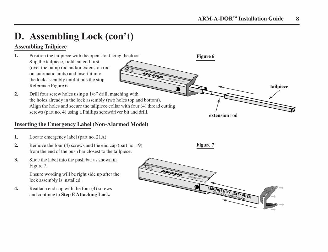
D. Assembling Lock (con’t)Assembling Tailpiece
1. Position the tailpiece with the open slot facing the door.Slip the tailpiece, field cut end first,(over the bump rod and/or extension rodon automatic units) and insert it intothe lock assembly until it hits the stop.Reference Figure 6.
2. Drill four screw holes using a 1/8” drill, matching withthe holes already in the lock assembly (two holes top and bottom).Align the holes and secure the tailpiece collar with four (4) thread cuttingscrews (part no. 4) using a Phillips screwdriver bit and drill.
Inserting the Emergency Label (Non-Alarmed Model)
1. Locate emergency label (part no. 21A).
2. Remove the four (4) screws and the end cap (part no. 19)from the end of the push bar closest to the tailpiece.
3. Slide the label into the push bar as shown inFigure 7.
Ensure wording will be right side up after thelock assembly is installed.
4. Reattach end cap with the four (4) screwsand continue to Step E Attaching Lock.
Figure 6
Figure 7
8ARM-A-DOR™ Installation Guide
tailpiece
extension rod
LN4055 10/3/05 4:28 PM Page 11
ARM-A-DOR™ Installation Guide9
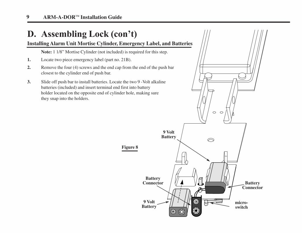
D. Assembling Lock (con’t)Installing Alarm Unit Mortise Cylinder, Emergency Label, and Batteries
Note: 1 1/8” Mortise Cylinder (not included) is required for this step.
1. Locate two piece emergency label (part no. 21B).
2. Remove the four (4) screws and the end cap from the end of the push barclosest to the cylinder end of push bar.
3. Slide off push bar to install batteries. Locate the two 9 -Volt alkalinebatteries (included) and insert terminal end first into batteryholder located on the opposite end of cylinder hole, making surethey snap into the holders.
micro-switch
9 VoltBattery
9 VoltBattery
BatteryConnector
BatteryConnector
Figure 8
LN4055 10/3/05 4:28 PM Page 12
D. Assembling Lock (con’t)Installing Alarm Unit Mortise Cylinder, Emergency Label, and Batteries (con’t)
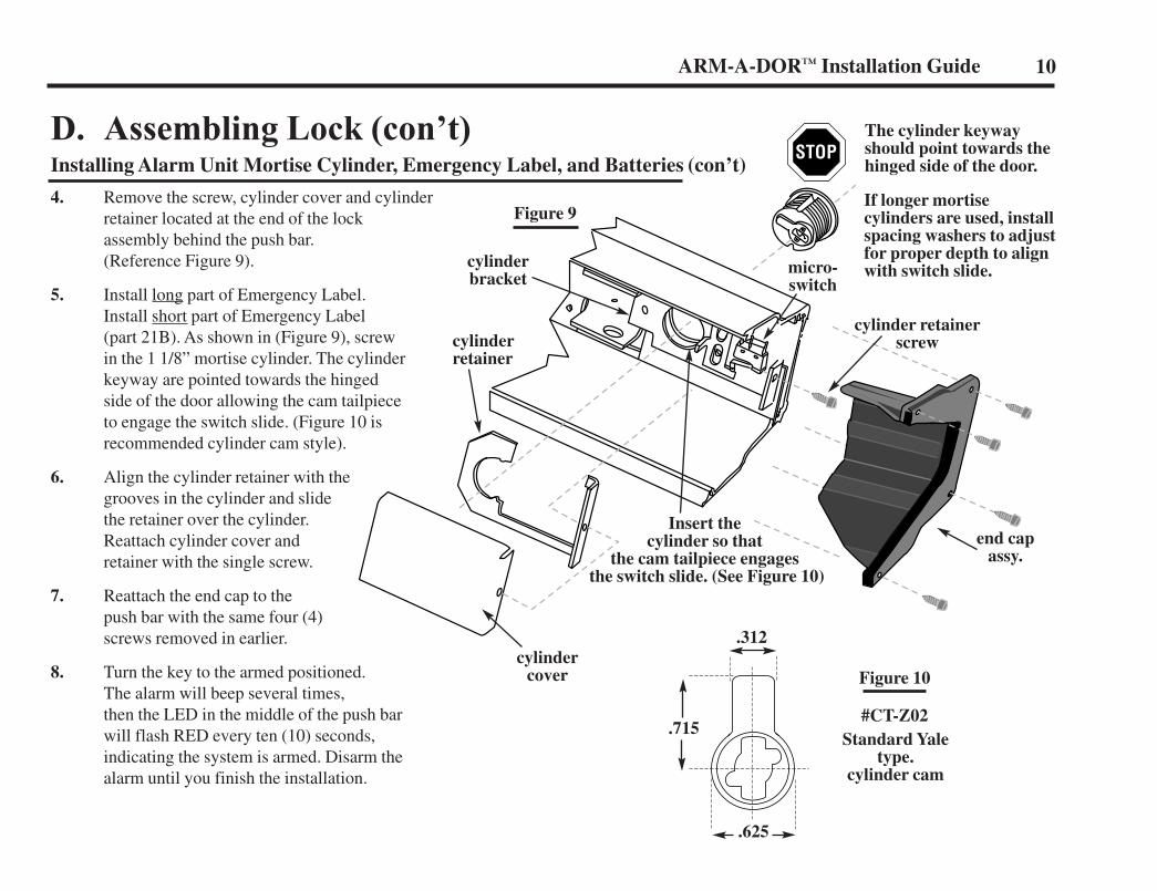
4. Remove the screw, cylinder cover and cylinderretainer located at the end of the lockassembly behind the push bar.(Reference Figure 9).
5. Install long part of Emergency Label.Install short part of Emergency Label(part 21B). As shown in (Figure 9), screwin the 1 1/8” mortise cylinder. The cylinderkeyway are pointed towards the hingedside of the door allowing the cam tailpieceto engage the switch slide. (Figure 10 isrecommended cylinder cam style).
6. Align the cylinder retainer with thegrooves in the cylinder and slidethe retainer over the cylinder.Reattach cylinder cover andretainer with the single screw.
7. Reattach the end cap to thepush bar with the same four (4)screws removed in earlier.
8. Turn the key to the armed positioned.The alarm will beep several times,then the LED in the middle of the push barwill flash RED every ten (10) seconds,indicating the system is armed. Disarm thealarm until you finish the installation.
Figure 9
The cylinder keyway should point towards the hinged side of the door.
If longer mortisecylinders are used, installspacing washers to adjustfor proper depth to alignwith switch slide.
cylinderretainer
cylindercover
cylinderbracket
Insert the cylinder so that
the cam tailpiece engagesthe switch slide. (See Figure 10)
micro-switch
cylinder retainerscrew
end capassy.
10ARM-A-DOR™ Installation Guide
Standard Yale type.
cylinder cam
#CT-Z02.715
.312
.625
Figure 10
LN4055 10/3/05 4:28 PM Page 13
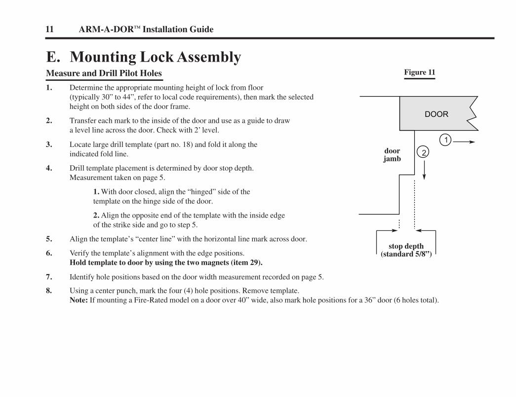
E. Mounting Lock AssemblyMeasure and Drill Pilot Holes
1. Determine the appropriate mounting height of lock from floor(typically 30” to 44”, refer to local code requirements), then mark the selectedheight on both sides of the door frame.
2. Transfer each mark to the inside of the door and use as a guide to drawa level line across the door. Check with 2’ level.
3. Locate large drill template (part no. 18) and fold it along theindicated fold line.
4. Drill template placement is determined by door stop depth.Measurement taken on page 5.
1. With door closed, align the “hinged” side of thetemplate on the hinge side of the door.
2. Align the opposite end of the template with the inside edgeof the strike side and go to step 5.
5. Align the template’s “center line” with the horizontal line mark across door.
6. Verify the template’s alignment with the edge positions.Hold template to door by using the two magnets (item 29).
7. Identify hole positions based on the door width measurement recorded on page 5.
8. Using a center punch, mark the four (4) hole positions. Remove template.Note: If mounting a Fire-Rated model on a door over 40” wide, also mark hole positions for a 36” door (6 holes total).
12
11 ARM-A-DOR™ Installation Guide
doorjamb
DOOR
stop depth(standard 5/8”)
Figure 11
LN4055 10/3/05 4:28 PM Page 14
12ARM-A-DOR™ Installation Guide
E. Mounting Lock Assembly (con’t)Locating and Drilling Door Pilot Hole (con’t)
9. If door jamb depth is greater than 6 3/4”, Low Profile Kit must be installed next.
10. Using a 1/4” drill bit, carefully drill straight and level pilot holes through the marks made on the door.Drill slowly in the event there is reinforcement in the door. Drill completely through the door.
11. Using a 3/8” drill bit redrill pilot holes through the inside skin of door only.
12. Facing the outside of the door, locate the pilot holes and use a 5/8” hole saw to drill only through the outside skin, anyreinforcement, and insulation of door. Caution!! Stop drilling before reaching the inside skin of door.
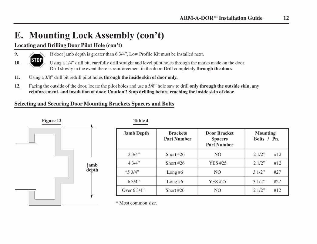
Selecting and Securing Door Mounting Brackets Spacers and Bolts
Figure 12 Table 4
Jamb Depth Brackets Door Bracket MountingPart Number Spacers Bolts / Pn.
Part Number
3 3/4” Short #26 NO 2 1/2” #12
4 3/4” Short #26 YES #25 2 1/2” #12
*5 3/4” Long #6 NO 3 1/2” #27
6 3/4” Long #6 YES #25 3 1/2” #27
Over 6 3/4” Short #26 NO 2 1/2” #12
* Most common size.
jambdepth
LN4055 10/3/05 4:28 PM Page 15
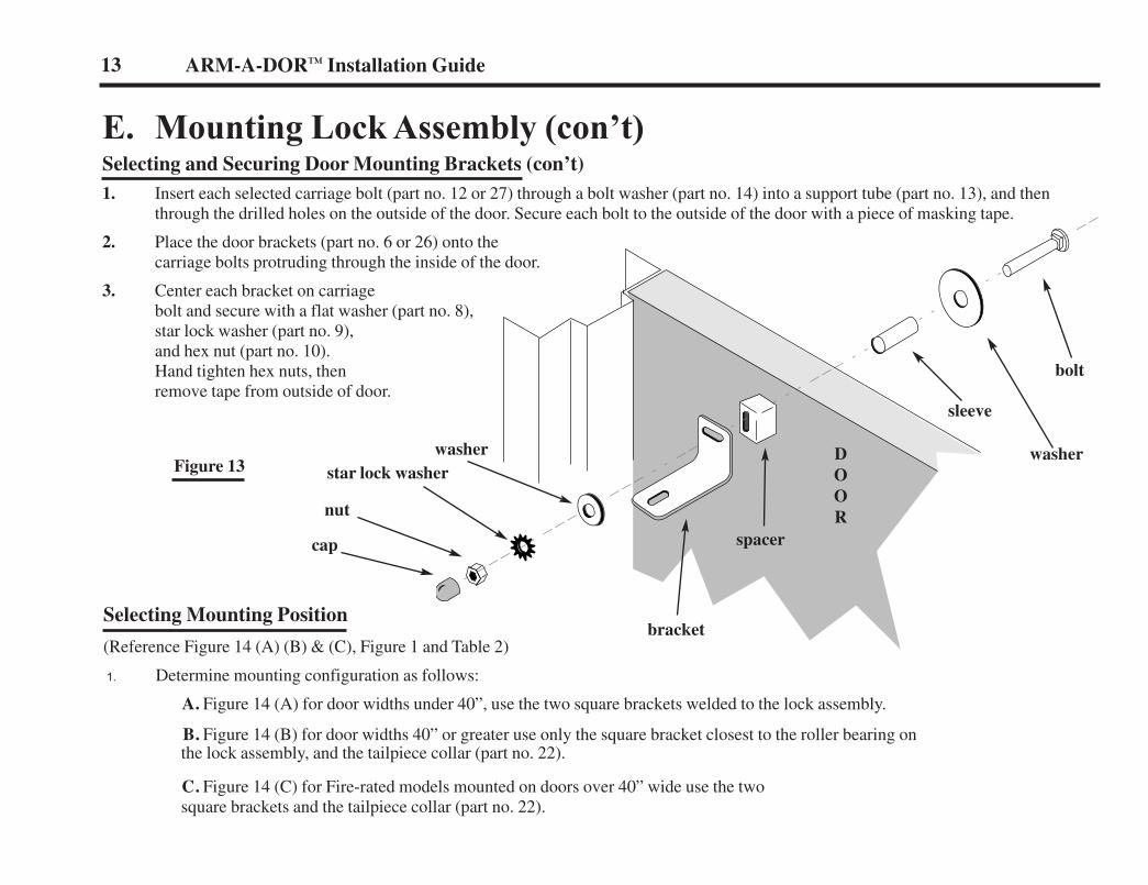
E. Mounting Lock Assembly (con’t)Selecting and Securing Door Mounting Brackets (con’t)1. Insert each selected carriage bolt (part no. 12 or 27) through a bolt washer (part no. 14) into a support tube (part no. 13), and then
through the drilled holes on the outside of the door. Secure each bolt to the outside of the door with a piece of masking tape.
2. Place the door brackets (part no. 6 or 26) onto thecarriage bolts protruding through the inside of the door.
3. Center each bracket on carriagebolt and secure with a flat washer (part no. 8),star lock washer (part no. 9),and hex nut (part no. 10).Hand tighten hex nuts, thenremove tape from outside of door.
13 ARM-A-DOR™ Installation Guide
Selecting Mounting Position
(Reference Figure 14 (A) (B) & (C), Figure 1 and Table 2)
1. Determine mounting configuration as follows:
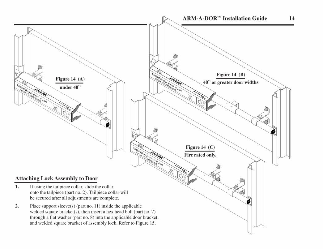
A. Figure 14 (A) for door widths under 40”, use the two square brackets welded to the lock assembly.
B. Figure 14 (B) for door widths 40” or greater use only the square bracket closest to the roller bearing on the lock assembly, and the tailpiece collar (part no. 22).
C. Figure 14 (C) for Fire-rated models mounted on doors over 40” wide use the twosquare brackets and the tailpiece collar (part no. 22).
DOOR
spacer
sleeve
washer
bolt
washer
bracket
star lock washer
nut
cap
Figure 13
LN4055 10/3/05 4:28 PM Page 16
14
ALARM
ALARM
OFFON
ALARM
ALARM
OFFON
Attaching Lock Assembly to Door1. If using the tailpiece collar, slide the collar
onto the tailpiece (part no. 2). Tailpiece collar willbe secured after all adjustments are complete.
2. Place support sleeve(s) (part no. 11) inside the applicablewelded square bracket(s), then insert a hex head bolt (part no. 7)through a flat washer (part no. 8) into the applicable door bracket,and welded square bracket of assembly lock. Refer to Figure 15.
Figure 14 (C)
Fire rated only.
Figure 14 (B)
40” or greater door widths
ALARM
ALARM
OFFON
Figure 14 (A)
under 40”
ARM-A-DOR™ Installation Guide
LN4055 10/3/05 4:28 PM Page 17
ALARMALARM
OFFON
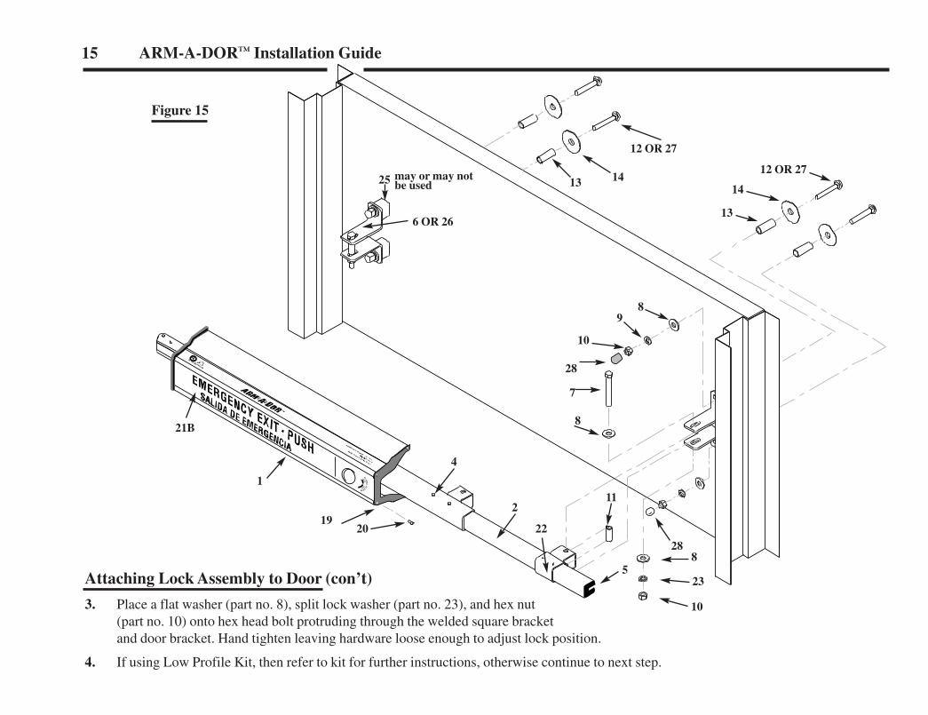
Attaching Lock Assembly to Door (con’t)
3. Place a flat washer (part no. 8), split lock washer (part no. 23), and hex nut(part no. 10) onto hex head bolt protruding through the welded square bracketand door bracket. Hand tighten leaving hardware loose enough to adjust lock position.
4. If using Low Profile Kit, then refer to kit for further instructions, otherwise continue to next step.
Figure 15
15 ARM-A-DOR™ Installation Guide
25 may or may notbe used
6 OR 26
1413
13
10
28
7
8
8
23
10
5
22
2
20
21B
1
19
11
4
98
12 OR 27
28
12 OR 27
14
LN4055 10/3/05 4:28 PM Page 18
16ARM-A-DOR™ Installation Guide
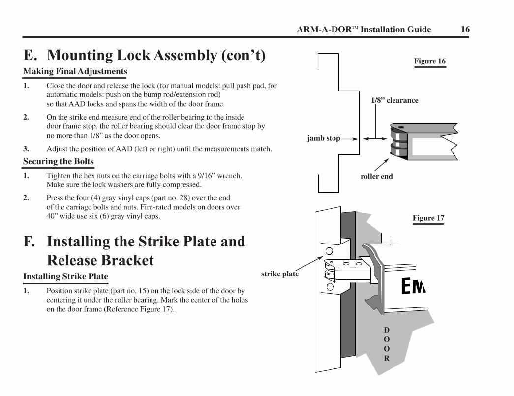
E. Mounting Lock Assembly (con’t)Making Final Adjustments
1. Close the door and release the lock (for manual models: pull push pad, forautomatic models: push on the bump rod/extension rod)so that AAD locks and spans the width of the door frame.
2. On the strike end measure end of the roller bearing to the insidedoor frame stop, the roller bearing should clear the door frame stop byno more than 1/8” as the door opens.
3. Adjust the position of AAD (left or right) until the measurements match.
Securing the Bolts
1. Tighten the hex nuts on the carriage bolts with a 9/16” wrench.Make sure the lock washers are fully compressed.
2. Press the four (4) gray vinyl caps (part no. 28) over the endof the carriage bolts and nuts. Fire-rated models on doors over40” wide use six (6) gray vinyl caps.
F. Installing the Strike Plate andRelease Bracket
Installing Strike Plate
1. Position strike plate (part no. 15) on the lock side of the door bycentering it under the roller bearing. Mark the center of the holeson the door frame (Reference Figure 17).
Figure 16
Figure 17
DOOR
1/8” clearance
jamb stop
roller end
strike plate
LN4055 10/3/05 4:28 PM Page 19
17 ARM-A-DOR™ Installation Guide
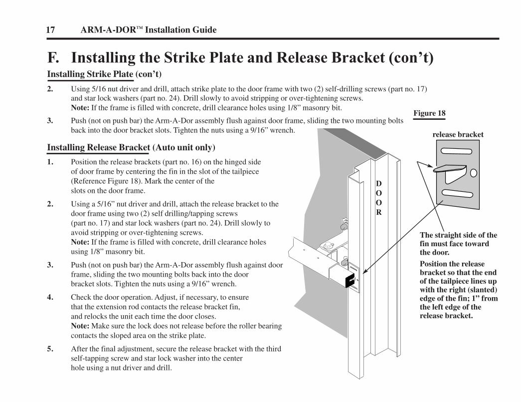
F. Installing the Strike Plate and Release Bracket (con’t)Installing Strike Plate (con’t)
2. Using 5/16 nut driver and drill, attach strike plate to the door frame with two (2) self-drilling screws (part no. 17)and star lock washers (part no. 24). Drill slowly to avoid stripping or over-tightening screws.Note: If the frame is filled with concrete, drill clearance holes using 1/8” masonry bit.
3. Push (not on push bar) the Arm-A-Dor assembly flush against door frame, sliding the two mounting boltsback into the door bracket slots. Tighten the nuts using a 9/16” wrench.
Installing Release Bracket (Auto unit only)
1. Position the release brackets (part no. 16) on the hinged sideof door frame by centering the fin in the slot of the tailpiece(Reference Figure 18). Mark the center of theslots on the door frame.
2. Using a 5/16” nut driver and drill, attach the release bracket to thedoor frame using two (2) self drilling/tapping screws(part no. 17) and star lock washers (part no. 24). Drill slowly toavoid stripping or over-tightening screws.Note: If the frame is filled with concrete, drill clearance holesusing 1/8” masonry bit.
3. Push (not on push bar) the Arm-A-Dor assembly flush against doorframe, sliding the two mounting bolts back into the doorbracket slots. Tighten the nuts using a 9/16” wrench.
4. Check the door operation. Adjust, if necessary, to ensurethat the extension rod contacts the release bracket fin,and relocks the unit each time the door closes.Note: Make sure the lock does not release before the roller bearingcontacts the sloped area on the strike plate.
5. After the final adjustment, secure the release bracket with the thirdself-tapping screw and star lock washer into the centerhole using a nut driver and drill.
Figure 18
The straight side of thefin must face towardthe door.
Position the releasebracket so that the endof the tailpiece lines upwith the right (slanted)edge of the fin; 1” fromthe left edge of the release bracket.
release bracket
DOOR
LN4055 10/3/05 4:28 PM Page 20
G. Attaching the Tailpiece End CapInsert the plastic end cap (part no. 5) into the end of the tailpiece, matching the contours of the two pieces and making sure it is secure inside the tailpiece.
H. Checking Door and Alarm OperationChecking Door Operation
The door should now be secure with less than 1/8” clearance between roller bearings and the strike plate. If too tight against the strike plate orrelease bracket, loosen nuts on the door brackets on the tight side, adjust lock, and retighten. Be sure to allow approximately 1/8” clearancebetween the tailpiece and door frame (stationary end), and 1/8” clearance between the roller bearings and strike plate (active end).
Checking Alarm Operation (Alarm Units Only)
Rearm alarm unit by turning the key to the armed positioned. The alarm will beep several times, and the Red LED in the middle of the pushpad will flash rapidly for twenty seconds. It will then flash every ten seconds, indicating the system is armed.
Installation is Now Complete!! Deliver the Keys and Owner’s Guide
to the Store Manager!!
18ARM-A-DOR™ Installation Guide
LN4055 10/3/05 4:28 PM Page 21

NOTES
LN4055 10/3/05 4:28 PM Page 22

NOTES
LN4055 10/3/05 4:28 PM Page 23

Corporate Headquarters6161 East 75th Street
Indianapolis, IN 46250 USA
Technical Support: 800-847-6750 www.precisionhardware.com