Installation Guide & Owner’s Manual - vrg.supportvrg.support/docs/VistaClear-HP-Manual.pdf · 2...
24
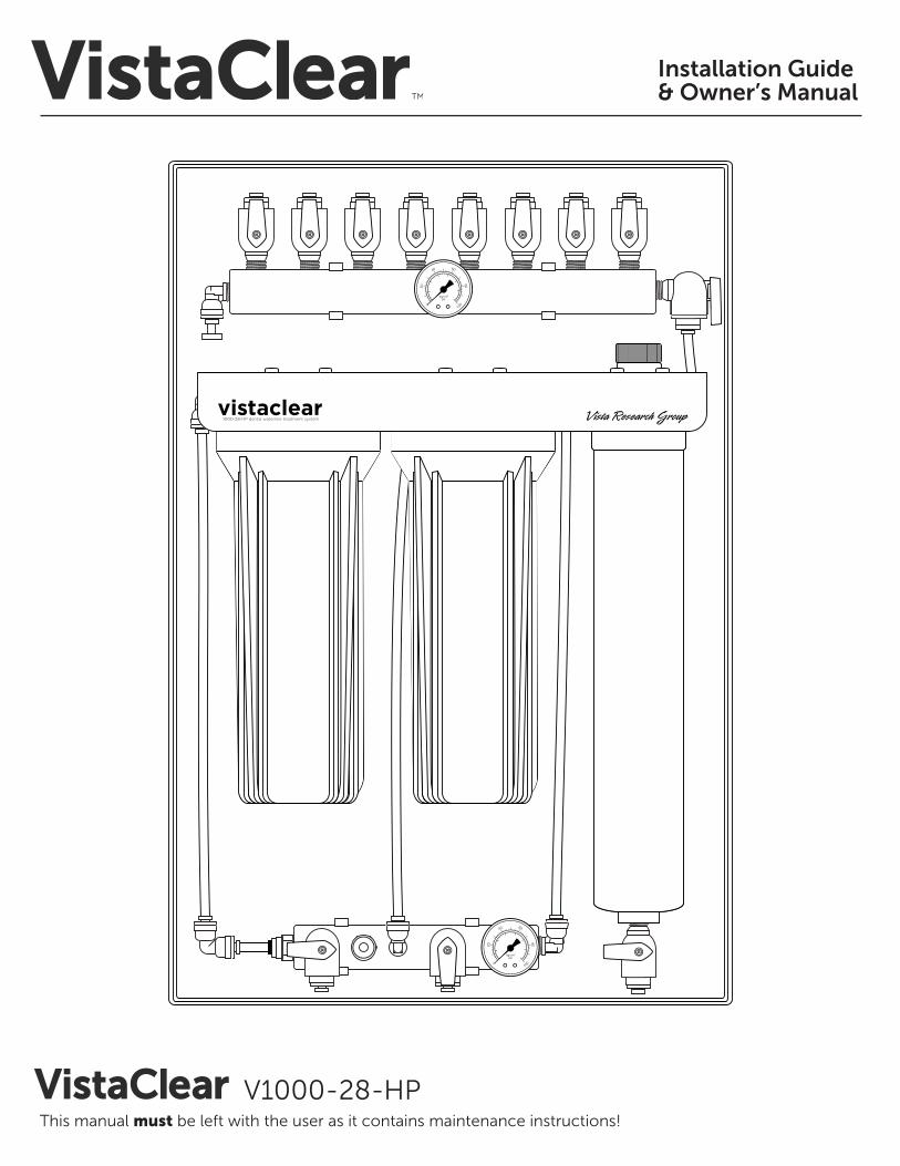
Installation Guide & Owner’s Manual V1000-28-HP This manual must be left with the user as it contains maintenance instructions!
Transcript of Installation Guide & Owner’s Manual - vrg.supportvrg.support/docs/VistaClear-HP-Manual.pdf · 2...
Installation Guide & Owner’s Manual
V1000-28-HPThis manual must be left with the user as it contains maintenance instructions!
2 VistaClear V1000-28-HP Installation Guide & Owner’s Manual
Table of Contents
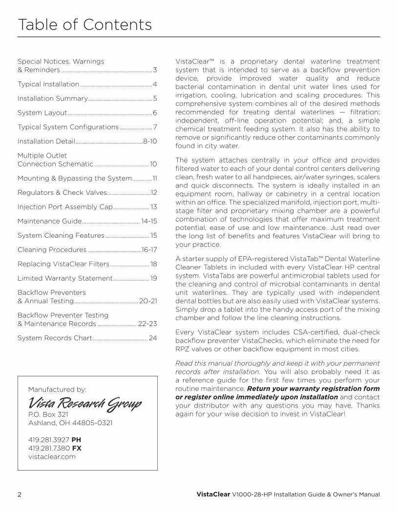
VistaClear™ is a proprietary dental waterline treatment system that is intended to serve as a backflow prevention device, provide improved water quality and reduce bacterial contamination in dental unit water lines used for irrigation, cooling, lubrication and scaling procedures. This comprehensive system combines all of the desired methods recommended for treating dental waterlines — filtration; independent, off-line operation potential; and, a simple chemical treatment feeding system. It also has the ability to remove or significantly reduce other contaminants commonly found in city water.
The system attaches centrally in your office and provides filtered water to each of your dental control centers delivering clean, fresh water to all handpieces, air/water syringes, scalers and quick disconnects. The system is ideally installed in an equipment room, hallway or cabinetry in a central location within an office. The specialized manifold, injection port, multi-stage filter and proprietary mixing chamber are a powerful combination of technologies that offer maximum treatment potential, ease of use and low maintenance. Just read over the long list of benefits and features VistaClear will bring to your practice.
A starter supply of EPA-registered VistaTab™ Dental Waterline Cleaner Tablets in included with every VistaClear HP central system. VistaTabs are powerful antimicrobial tablets used for the cleaning and control of microbial contaminants in dental unit waterlines. They are typically used with independent dental bottles but are also easily used with VistaClear systems. Simply drop a tablet into the handy access port of the mixing chamber and follow the line cleaning instructions.
Every VistaClear system includes CSA-certified, dual-check backflow preventer VistaChecks, which eliminate the need for RPZ valves or other backflow equipment in most cities.
Read this manual thoroughly and keep it with your permanent records after installation. You will also probably need it as a reference guide for the first few times you perform your routine maintenance. Return your warranty registration form or register online immediately upon installation and contact your distributor with any questions you may have. Thanks again for your wise decision to invest in VistaClear!
Special Notices, Warnings & Reminders ..........................................................3
Typical Installation ..............................................4
Installation Summary .........................................5
System Layout ......................................................6
Typical System Configurations .....................7
Installation Detail ...........................................8-10
Multiple Outlet Connection Schematic ................................... 10
Mounting & Bypassing the System .............11
Regulators & Check Valves ............................12
Injection Port Assembly Cap ....................... 13
Maintenance Guide ..................................... 14-15
System Cleaning Features ............................ 15
Cleaning Procedures ..................................16-17
Replacing VistaClear Filters ......................... 18
Limited Warranty Statement ....................... 19
Backflow Preventers & Annual Testing ......................................... 20-21
Backflow Preventer Testing & Maintenance Records ......................... 22-23
System Records Chart ................................... 24
Manufactured by:
P.O. Box 321Ashland, OH 44805-0321
419.281.3927 PH419.281.7380 FXvistaclear.com
3© 2000-2016 VRG, LLC. All rights reserved.
Special Notices, Warnings & Reminders
To ensure that your new VistaClear Dental Waterline Treatment System provides many years of trouble free service, please observe the following:
1. Read the complete Installation Guide & Owner’s Manual to completely understand the installation, maintenance, capabilities and limitations of the system.
2. We strongly recommended that plumbing required for this system be done by a trained, authorized professional contractor who is familiar with all local codes working in conjunction with an authorized dental dealer technicians. See pages 4 & 8 for system plumbing and water quality specifications.
3. Both filter elements should be changed at least once per year or after every 800 gallons (3,028 liters) of use, which ever occurs first.
4. All VistaCheck backflow preventer check valves downstream of the Distribution Manifold on the system should be checked at least once per year to make certain they are working properly. Follow the steps on page 20-21 to perform this simple but important testing procedure. This is best done while changing the filter elements.
5. BYPASSING THE SYSTEM: Every VistaClear central system comes configured
with the ability to bypass the system during emergencies and/or required system maintenance/repair during business hours.
a. The red bypass line tubing is provided but never “connected” by the manufacturer.
b. The bypass line should never be “connected” during general installation.
c. If the system is ever bypassed for any reason, it should be bypassed for only as long as is necessary to accomplish the maintenance or repair and disconnected as soon as possible.
d. If the system is ever bypassed for any reason, a complete system cleansing procedure should be performed as described on page 16 & 17.
6. The system should never be operated unless filter elements are installed their proper location.
7. Remember to complete and return the warranty registration form or register online immediately upon installation. It is very important that we receive your registration so that we can 1) place your name in the national VistaClear systems registry, 2) send you a reminder to change your filter elements and test your backflow preventers, 3) notify you of improved, streamlined maintenance procedures or new line cleaning agents, and 4) send you system registry certificates and patient pamphlets.
IMPORTANT PRODUCT INFORMATION
VistaClear for use in dental offices is a complete manufactured assembly for process water that, as a system, is a Class I medical device subject to FDA requirements. The system is used for filtering water for use during patient care in dental operatories while also serving as a backflow prevention device. When installed and maintained properly it helps provide improved water quality by reducing submicron particulate, organic and inorganic contaminants including certain microbiological organisms that may be present in the source water.
Each VistaClear system includes CSA certified VistaCheck dual check valve backflow preventers for use on the compressed air and potable water inlets and each treated water outlet; air and water pressure regulators; specialty water treatment filters; air gap drain fitting; control and distribution manifolds; pressure gauges; a mixing chamber, injection port and threaded plug for the administration of periodic cleaners and antimicrobials; a starter supply of VistaTab antimicrobial cleaner tablets and, 1/4” O.D. tubing, fittings and valves. The system is to be installed by a trained dental equipment technician and/or suitable plumbing subcontractor and maintained by trained dental staff.
Use of a VistaClear system does not, by itself, eliminate the need for proper user maintenance. Due to the nature and complex design of dental delivery units, the periodic use of approved waterline cleaners and antimicrobials is extremely important for proper dental waterline care. According to the CDC, even sterile water delivered to a typical dental delivery unit can be quickly contaminated due to a combination of factors including tiny diameter tubings, fittings and ports; laminar water flow; low volume water use; slow flow rates; acquiescing to warmer room temperatures and the use of quick connect fittings, handpieces, air water syringes and attached scaling devices that can introduce contamination from the environment in addition to insufficient periodic user maintenance. For these reasons, Vista Research Group, LLC, does not make specific bacteria reduction claims.
It is recommended that water quality testing for HPC (heterotrophic plate count) organisms should be done on a regular basis using either in-office test kits or laboratories certified to perform such tests. Should HPC counts exceed desired levels, the waterlines should be flushed and cleaned using approved antimicrobial cleaners like VistaTab.
4 VistaClear V1000-28-HP Installation Guide & Owner’s Manual
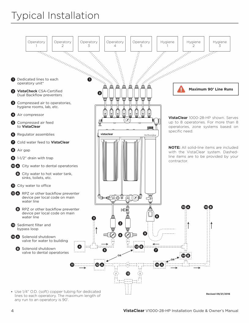
Dedicated lines to eachoperatory unit*
VistaCheck CSA-CertifiedDual Backflow preventers
Compressed air to operatories, hygiene rooms, lab, etc.
Air compressor
Compressed air feed to VistaClear
Regulator assemblies
Cold water feed to VistaClear
Air gap
1-1/2” drain with trap
City water to dental operatories
City water to hot water tank, sinks, toilets, etc.
City water to o�ce
RPZ or other backflow preventer device per local code on main water line
RPZ or other backflow preventer device per local code on main water line
Sediment filter and bypass loop
Solenoid shutdown valve for water to building
Solenoid shutdown valve to dental operatories
Operatory1
Operatory2
Operatory3
Operatory4
Operatory5
Hygiene1
Hygiene2
Hygiene3
A
A
B
B
A
B
A
B
A B
B
A
OR
OR
Revised 09/21/2016
Typical Installation
VistaClear 1000-28-HP shown. Serves up to 8 operatories. For more than 8 operatories, zone systems based on specific need.
NOTE: All solid-line items are included with the VistaClear system. Dashed-line items are to be provided by your contractor.
* Use 1/4” O.D. (soft) copper tubing for dedicated lines to each operatory. The maximum length of any run to an operatory is 90’.
Maximum 90’ Line Runs
5© 2000-2016 VRG, LLC. All rights reserved.
Installation Summary
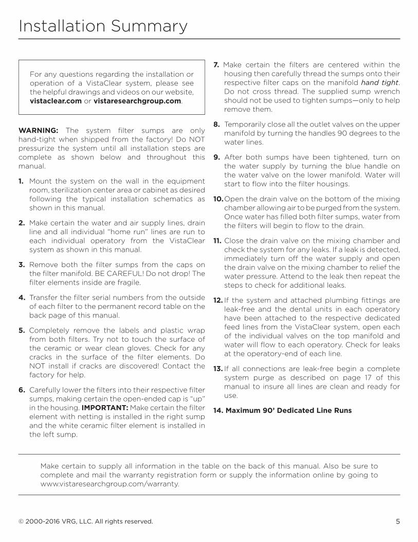
WARNING: The system filter sumps are only hand-tight when shipped from the factory! Do NOT pressurize the system until all installation steps are complete as shown below and throughout this manual.
1. Mount the system on the wall in the equipment room, sterilization center area or cabinet as desired following the typical installation schematics as shown in this manual.
2. Make certain the water and air supply lines, drain line and all individual “home run” lines are run to each individual operatory from the VistaClear system as shown in this manual.
3. Remove both the filter sumps from the caps on the filter manifold. BE CAREFUL! Do not drop! The filter elements inside are fragile.
4. Transfer the filter serial numbers from the outside of each filter to the permanent record table on the back page of this manual.
5. Completely remove the labels and plastic wrap from both filters. Try not to touch the surface of the ceramic or wear clean gloves. Check for any cracks in the surface of the filter elements. Do NOT install if cracks are discovered! Contact the factory for help.
6. Carefully lower the filters into their respective filter sumps, making certain the open-ended cap is “up” in the housing. IMPORTANT: Make certain the filter element with netting is installed in the right sump and the white ceramic filter element is installed in the left sump.
7. Make certain the filters are centered within the housing then carefully thread the sumps onto their respective filter caps on the manifold hand tight. Do not cross thread. The supplied sump wrench should not be used to tighten sumps—only to help remove them.
8. Temporarily close all the outlet valves on the upper manifold by turning the handles 90 degrees to the water lines.
9. After both sumps have been tightened, turn on the water supply by turning the blue handle on the water valve on the lower manifold. Water will start to flow into the filter housings.
10. Open the drain valve on the bottom of the mixing chamber allowing air to be purged from the system. Once water has filled both filter sumps, water from the filters will begin to flow to the drain.
11. Close the drain valve on the mixing chamber and check the system for any leaks. If a leak is detected, immediately turn off the water supply and open the drain valve on the mixing chamber to relief the water pressure. Attend to the leak then repeat the steps to check for additional leaks.
12. If the system and attached plumbing fittings are leak-free and the dental units in each operatory have been attached to the respective dedicated feed lines from the VistaClear system, open each of the individual valves on the top manifold and water will flow to each operatory. Check for leaks at the operatory-end of each line.
13. If all connections are leak-free begin a complete system purge as described on page 17 of this manual to insure all lines are clean and ready for use.
14. Maximum 90’ Dedicated Line Runs
Make certain to supply all information in the table on the back of this manual. Also be sure to complete and mail the warranty registration form or supply the information online by going to www.vistaresearchgroup.com/warranty.
For any questions regarding the installation or operation of a VistaClear system, please see the helpful drawings and videos on our website, vistaclear.com or vistaresearchgroup.com.
6 VistaClear V1000-28-HP Installation Guide & Owner’s Manual
System Layout
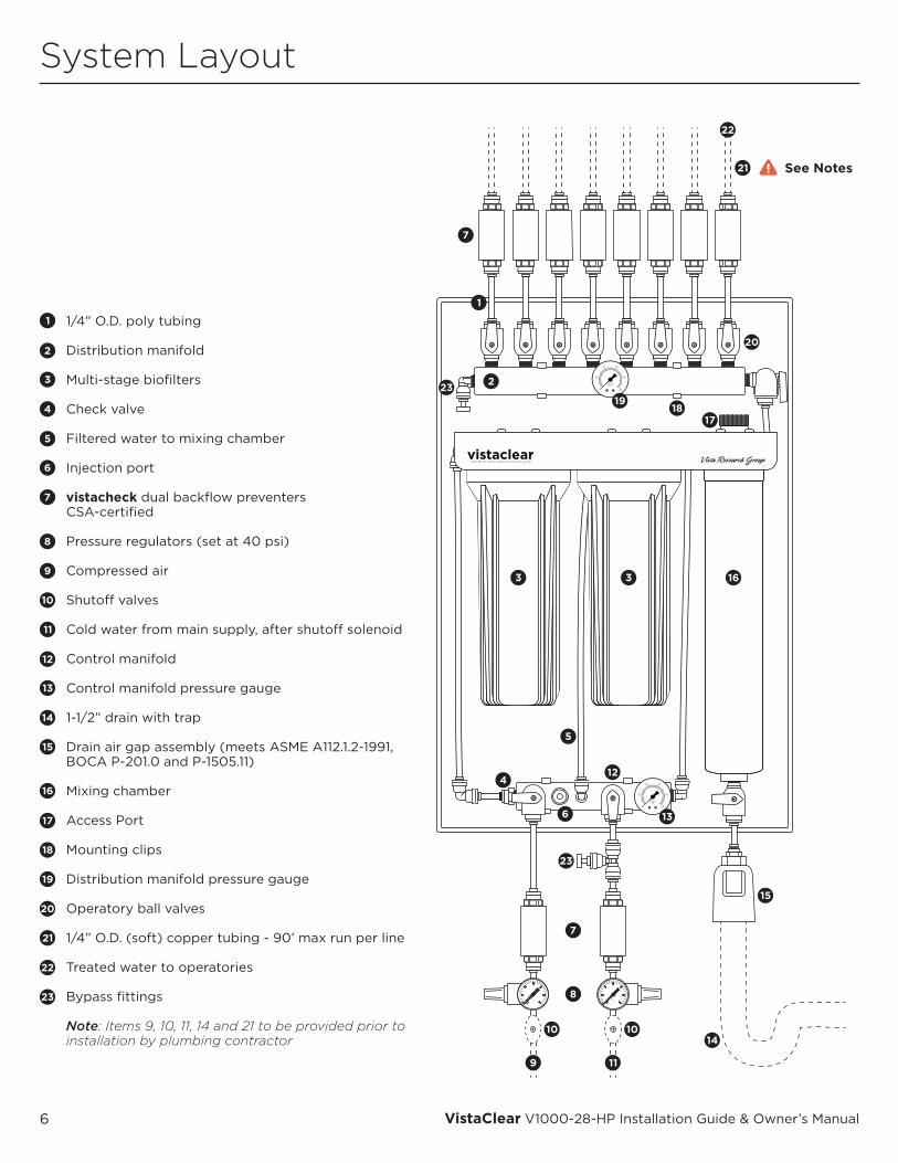
1/4” O.D. poly tubing
Distribution manifold
Multi-stage biofilters
Check valve
Filtered water to mixing chamber
Injection port
vistacheck dual backflow preventers CSA-certified
Pressure regulators (set at 40 psi)
Compressed air
Shuto� valves
Cold water from main supply, after shuto� solenoid
Control manifold
Control manifold pressure gauge
1-1/2” drain with trap
Drain air gap assembly (meets ASME A112.1.2-1991, BOCA P-201.0 and P-1505.11)
Mixing chamber
Access Port
Mounting clips
Distribution manifold pressure gauge
Operatory ball valves
1/4” O.D. (soft) copper tubing - 90’ max run per line
Treated water to operatories
Bypass fittings
Note: Items 9, 10, 11, 14 and 21 to be provided prior to installation by plumbing contractor
See Notes
7© 2000-2016 VRG, LLC. All rights reserved.
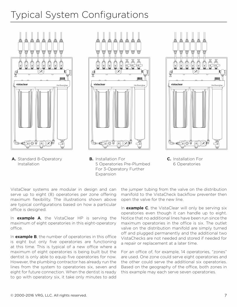
Typical System Configurations
A. Standard 8-Operatory Installation
B. Installation For 5 Operatories Pre-Plumbed For 3-Operatory Further Expansion
C. Installation For 6 Operatories
VistaClear systems are modular in design and can serve up to eight (8) operatories per zone offering maximum flexibility. The illustrations shown above are typical configurations based on how a particular office is designed.
In example A, the VistaClear HP is serving the maximum of eight operatories in this eight-operatory office.
In example B, the number of operatories in this office is eight but only five operatories are functioning at this time. This is typical of a new office where a maximum of eight operatories is being built but the dentist is only able to equip five operatories for now. However, the plumbing contractor has already run the lines from the system to operatories six, seven and eight for future connection. When the dentist is ready to go with operatory six, it take only minutes to add
the jumper tubing from the valve on the distribution manifold to the VistaCheck backflow preventer then open the valve for the new line.
In example C, the VistaClear will only be serving six operatories even though it can handle up to eight. Notice that no additional lines have been run since the maximum operatories in the office is six. The outlet valve on the distribution manifold are simply turned off and plugged permanently and the additional two VistaChecks are not needed and stored if needed for a repair or replacement at a later time.
For an office of, for example, 14 operatories, “zones” are used. One zone could serve eight operatories and the other could serve the additional six operatories. Based on the geography of the office, both zones in this example may each serve seven operatories.
8 VistaClear V1000-28-HP Installation Guide & Owner’s Manual
Installation Detail
The VistaClear Dental Waterline Treatment System is intended to serve as a backflow prevention device, provide improved water quality and reduce bacterial contamination in dental unit waterlines used for irrigation, cooling, lubrication and scaling procedures. It is designed for installation centrally with dedicated lines running to each operatory. Although actual installation of VistaClear is quite simple, it is recommended that a professional technician familiar with dental operatory systems perform the installation due to the wide variety of possible options, running of water and air lines, drain lines, etc. He/she should be familiar with the local plumbing codes and techniques for successful dental equipment installations.
Please read this and all other information before proceeding with installation and operation.
Please make certain that anyone responsible for future operation and maintenance of the system is familiar with all details contained in the maintenance manual.
Please keep the owner’s manual & maintenance guide handy for future reference.
Please return the Warranty / Registration form or register online immediately upon installation.
Always follow local plumbing codes.
UNPACKING:Carefully unpack the contents of the product carton. It should include the system, Installation Guide and Owner’s Manual, Warranty Registration sheet, an accessory pack that includes two regulator assemblies, an air gap drain, VistaTabs, VistaChecks, a 35cc plastic syringe, connector fittings, tubing, etc. Check to make certain there was no damage during shipment. If damage is evident, contact the shipping company immediately.
DATA:There are serial tags on the mounting board and the back of each filter element of the system. The data for each should already be recorded on the Warranty Registration sheet. If the numbers were not recorded during manufacture, locate each number and record them on the yellow Warranty Registration sheet. The serial number for the system (on the mounting board) is a permanent number for the life of the system. The serial number on the filter elements will change each time the elements are replaced (at least annually). Write the date of installation and the installer’s name on the label found on the mounting board. You must use a fine tip, permanent marker (e.g. a Sharpie®) or some other writing instrument that will not smear.
TOOLS:Required tools vary but typically include a sharp razor knife or tubing cutter, measuring tape, drill, assorted bits and screws, screwdrivers, wrenches, cotton swabs and clean rags.
LOCATION:The VistaClear system should generally be installed centrally within the dental office. It is normally installed in the equipment room, sterilization center, hallway or laboratory either mounted on a wall or inside cabinetry. The system must ALWAYS be mounted vertically. Any pressurized supply of water (potable municipal water or properly treated well water), compressed air and a drain should be nearby the system. In deciding where to install the system, remember that the goal is to filter all of the water that is delivered to the dental control center for use in handpieces, air/water syringes, scalers and quick disconnects through the dedicated lines that run from the system to each operatory. Dedicated 1/4” O.D. (soft) copper lines must be run to each operatory from the central system.
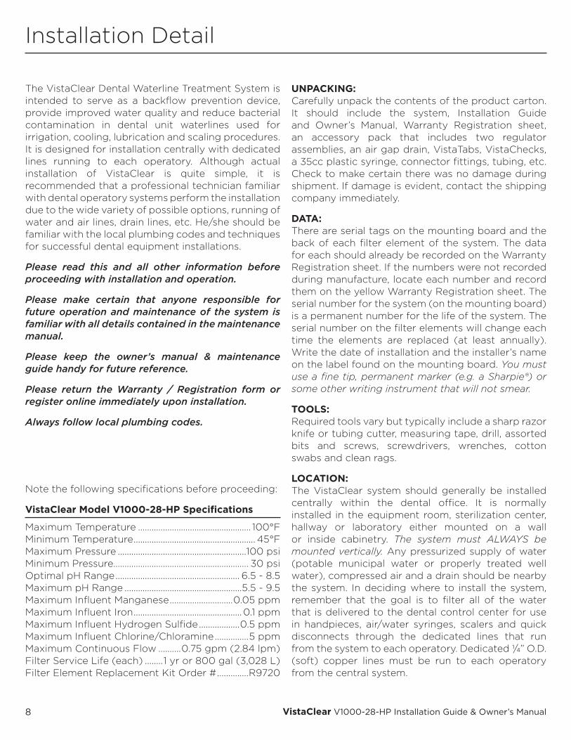
Note the following specifications before proceeding:
VistaClear Model V1000-28-HP Specifications
Maximum Temperature .................................................. 100°FMinimum Temperature ...................................................... 45°FMaximum Pressure .........................................................100 psiMinimum Pressure............................................................ 30 psiOptimal pH Range ....................................................... 6.5 - 8.5Maximum pH Range ....................................................5.5 - 9.5Maximum Influent Manganese ............................0.05 ppmMaximum Influent Iron ................................................ 0.1 ppmMaximum Influent Hydrogen Sulfide ..................0.5 ppmMaximum Influent Chlorine/Chloramine ...............5 ppmMaximum Continuous Flow ..........0.75 gpm (2.84 lpm)Filter Service Life (each) ........1 yr or 800 gal (3,028 L)Filter Element Replacement Kit Order # ..............R9720
9© 2000-2016 VRG, LLC. All rights reserved.
MOUNTING:See the supplementary information on page 11 for mounting tips.
TUBING & CONNECTIONS: Fittings and valves used on the VistaClear system are patented “push-to-connect” thermoplastic. Components are manufactured from FDA-compliant materials and are NSF-51 listed. Use the included tubing to go from the valves on the distribution manifold to the VistaCheck backflow preventers. A supply of blue tubing is included for cutting short transition pieces between the connectors and valves. Heavy wall tubing must be 1/4” O.D. and is included. Regulator assemblies including gauges, 3/8” compression tube, and 1/4” transition fittings have been included for making inlet connections for the air and water supply lines.
!!! IMPORTANT !!! All tubing must have square-cut ends with NO burrs and NO scars on the surface of the tubing. Burrs can easily damage the internal “O” rings and scars/scratches on the surface of the tubing can create a leak path for water to get by the “O” ring that will cause a leak. It is strongly recommended that installers use a sharp tubing cutter designed for small diameter poly tubing or, if not available, use a sharp razor knife. For copper lines, use a copper tubing cutter and use a file and steel wool on the tip to remove any and all burrs. If a leak occurs, depressurize the system, remove the tubing, cut a new end and replace. Make certain that the tubing is fully inserted – plunge depth is 11/16”. If the connection still leaks, the fitting or valve “O” ring may have been permanently damaged and will need to be replaced.
TUBING COLOR CODE:1. Unfiltered Water – RED2. Filtered Outlet Water to Mixing Chamber – BLUE 3. Outlet to Distribution Manifold – BLUE4. Compressed Air Inlet – YELLOW5. Drain – CLEAR6. System Tubing – BLUE
TUBING INSTALLATION SUMMARY:1. Make certain ends of tubing are square and clean.2. Mark tubing 11/16” back from end – this is the tubing
plunge depth into the fitting.3. To install — Push tubing into fitting until it bottoms
out – the mark you made on the tubing will help you see that the tubing has been pushed completely into each fitting. A slight twist while pushing helps.
4. To remove — Depress collet and pull tubing out. A gentle twist while pulling helps the tubing release.
WATER SOURCE:Water to be treated by the VistaClear system should come from a pressurized municipal water supply only. The system is designed to filter only COLD water.
DRAINS:The system drain is found at the bottom of the mixing chamber and should be connected with clear tubing to the BOCA/ANSI approved air gap drain that is included with each system. It is designed to be solvent welded to a 1-1/2” PVC standpipe (12” minimum) with trap (see drawing). Please check your local plumbing codes for proper drain installation regulations and techniques.
PRESSURIZING & TESTING THE SYSTEM:Check to see that all tubing connections are made correctly. Close all of the valves on the distribution manifold. Make certain the filtered water manifold valve on the right end of the distribution manifold is open. Close the “Drain” and “Air Inlet” valves and slowly open the “Water Inlet” valve allowing water to enter the system. As the system is filled with water and pressurized, check for any leaks. Open the “Drain” valve and allow water to run to drain for a few minutes. Close the “Drain” valve and slowly open each valve on the distribution manifold allowing water to run to each operatory. Discharge each air/water syringe, handpiece and other dental appliances connected to the system. Make certain that all appliances are receiving water and are working properly. Now close the “Water Inlet” valve and open the “Air Inlet” valve. Open the drain valve on the Mixing Chamber
10 VistaClear V1000-28-HP Installation Guide & Owner’s Manual
To Assistant’sSystem
To Dental Chair Junction Box Shut-O�
Valve
Shut-O�Valve
From VistaClearFilter
until water is gone and air emerges. Close drain. Discharge the appliances until the water is gone and air emerges. This is how to clear all lines of water and prepare for line cleaning or when a system is to be shut-down for a period of time. Holding each appliance line open for a few moments when valves are in these positions will “dry” lines. Now close the “Air Inlet” valve, open the “Water Inlet” valve and let the system fill with water and pressurize. Once again check for leaks. The installation is now complete. Consult the “Owner’s Manual and Maintenance Guide” section for operational instructions.
PREPARING THE SYSTEM FOR USE:After making certain there are no leaks in the system, follow the steps in the “Line Cleansing Procedure”
of the Owner’s Manual and Maintenance Guide. The goal is to perform an aggressive cleaning of all the dental waterlines. Allow the cleaner to remain in the lines for the proper length of time the follow the “Line Rinsing” procedure. VistaTabs are used as needed for a thorough antimicrobial cleaning of the waterlines. The system will then be ready for use.
Make certain to train office staff on the proper operation and maintenance of the system.
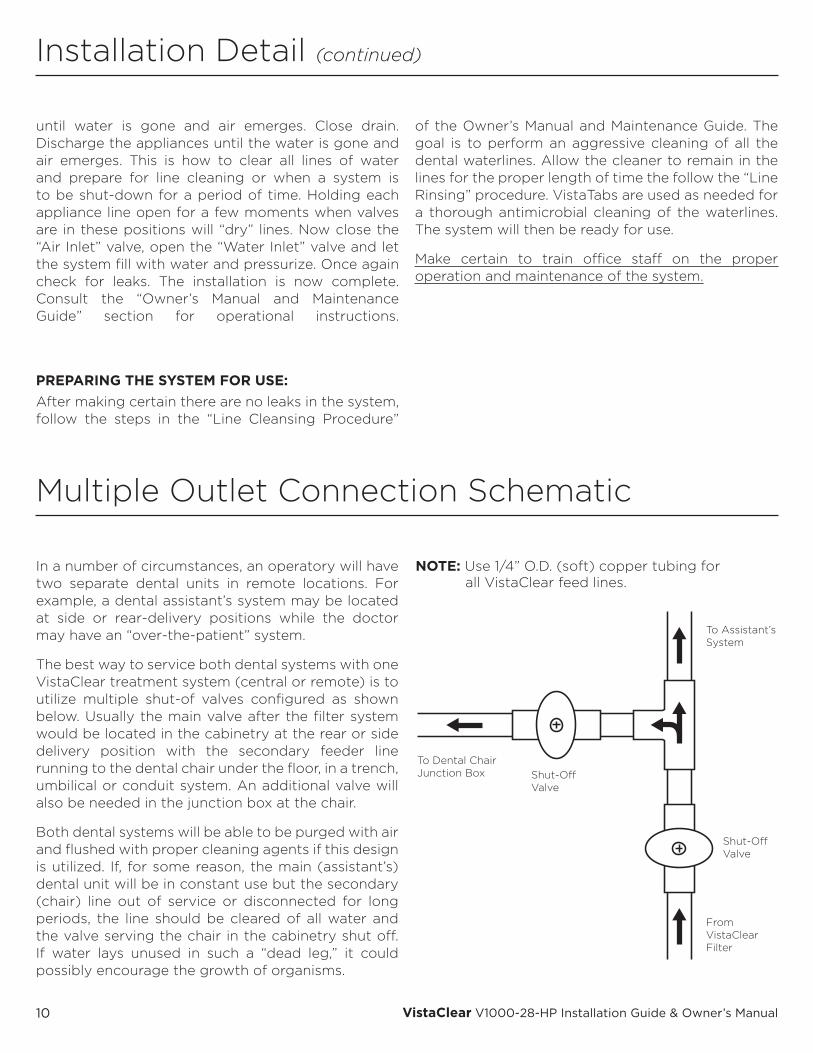
In a number of circumstances, an operatory will have two separate dental units in remote locations. For example, a dental assistant’s system may be located at side or rear-delivery positions while the doctor may have an “over-the-patient” system.
The best way to service both dental systems with one VistaClear treatment system (central or remote) is to utilize multiple shut-of valves configured as shown below. Usually the main valve after the filter system would be located in the cabinetry at the rear or side delivery position with the secondary feeder line running to the dental chair under the floor, in a trench, umbilical or conduit system. An additional valve will also be needed in the junction box at the chair.
Both dental systems will be able to be purged with air and flushed with proper cleaning agents if this design is utilized. If, for some reason, the main (assistant’s) dental unit will be in constant use but the secondary (chair) line out of service or disconnected for long periods, the line should be cleared of all water and the valve serving the chair in the cabinetry shut off. If water lays unused in such a “dead leg,” it could possibly encourage the growth of organisms.
Installation Detail (continued)
Multiple Outlet Connection Schematic
NOTE: Use 1/4” O.D. (soft) copper tubing for all VistaClear feed lines.

11© 2000-2016 VRG, LLC. All rights reserved.
Mounting the System
Bypassing the SystemEvery multiple operatory VistaClear system comes with a bypass feature. However, the bypass tubing is NOT to be connected during installation! The bypass loop serves two purposes as follows: 1. In the event of a malfunction or leak in the system, the clinical staff can bypass
the filter network sending unfiltered water to the operatories while service technicians are in route to fix the problem. Although there has never been a need for this to date, the fact that it can be done would allow a dental office to continue patient services without interruption.
2. A service technician can bypass the system to allow unfiltered water to operatories while performing a repair, filter change, etc.
BYPASSING THE FILTER SYSTEM: A. Turn off the air and water supply
valves (1). B. Open the drain valve (2). C. Open the air and water valves on the
control manifold (3). This relieves all system pressure.
D. Remove the plug from the Tee (4) and elbow fitting (5).
E. Connect one end of the provided red tubing (6) to elbow (5).
F. Connect the other end of the red tubing (6) to the Tee (4).
G. Close service valve (8). H. Close both the air and water valves
on the control manifold (3).I. Close drain valve (2).J. Open the water valve (1) and
unfiltered water will fill the distribution manifold and flow to the operatories.
VistaClear central systems can be flush mounted on walls, built into cabinets, etc. in equipment rooms, labs, sterilization centers or other locations to suit the needs of the individual dental office. Since each unit weighs less than 25 lbs., mounting can be accomplished using standard lag screws of proper length.
Hold the system in the desired location and mark the outer boundaries of the mounting board. Determine the best places for installing a minimum of two (2) screws for the system. Measure and mark the corresponding locations on the mounting board and drill pilot holes.
SUGGESTIONS: 1. Wherever possible, locate at least one of the anchors so that it penetrates
a stud or other support structure. If no studs are available, be certain to use proper anchors for mounting on wallboard.
2. Try to locate anchor pilot holes behind filter housings and manifolds in order to “hide” anchors. The line drawing to the right shows an “X” at good mounting points that hide anchors. Simply remove the filter housing(s) and/or pull the desired filter / manifold out of the clips, drill pilot, anchor and then replace.
Reverse the steps to convert back to filtration bypass mode. Disconnect, drain and stow bypass tubing. Replace plugs in elbow (5) and tee (4). Be sure to run VistaClean or another cleaner through the lines after bypassing since all tubing will have been exposed to unfiltered water.
12 VistaClear V1000-28-HP Installation Guide & Owner’s Manual
Regulators & Check Valves
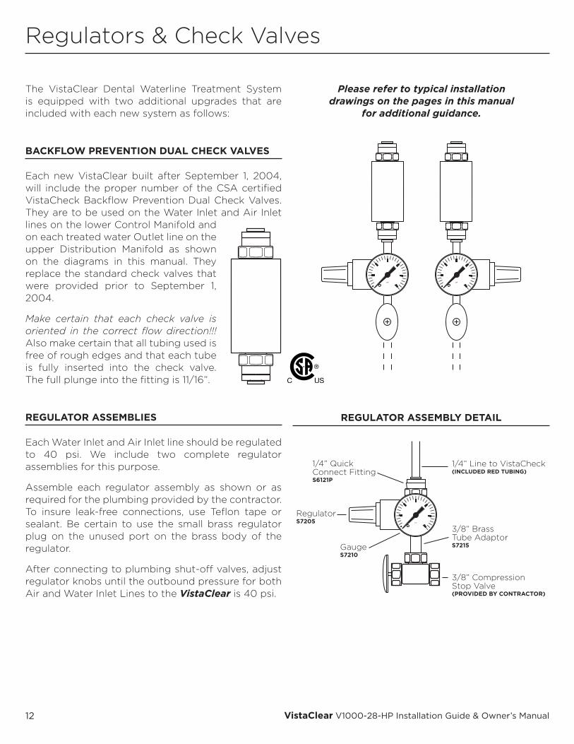
The VistaClear Dental Waterline Treatment System is equipped with two additional upgrades that are included with each new system as follows:
BACKFLOW PREVENTION DUAL CHECK VALVES
Each new VistaClear built after September 1, 2004, will include the proper number of the CSA certified VistaCheck Backflow Prevention Dual Check Valves. They are to be used on the Water Inlet and Air Inlet lines on the lower Control Manifold and on each treated water Outlet line on the upper Distribution Manifold as shown on the diagrams in this manual. They replace the standard check valves that were provided prior to September 1, 2004.
Make certain that each check valve is oriented in the correct flow direction!!! Also make certain that all tubing used is free of rough edges and that each tube is fully inserted into the check valve. The full plunge into the fitting is 11/16”.
REGULATOR ASSEMBLIES
Each Water Inlet and Air Inlet line should be regulated to 40 psi. We include two complete regulator assemblies for this purpose.
Assemble each regulator assembly as shown or as required for the plumbing provided by the contractor. To insure leak-free connections, use Teflon tape or sealant. Be certain to use the small brass regulator plug on the unused port on the brass body of the regulator.
After connecting to plumbing shut-off valves, adjust regulator knobs until the outbound pressure for both Air and Water Inlet Lines to the VistaClear is 40 psi.
REGULATOR ASSEMBLY DETAIL
Please refer to typical installation drawings on the pages in this manual
for additional guidance.
I I I
I I I
I I I I
I I I I I I I I I I I I I I I I I
I I
psiI I I
I I I
I I I I
I I I I I I I I I I I I I I I I I
I I
psi
1/4” QuickConnect FittingS6121P
GaugeS7210
RegulatorS7205
1/4” Line to VistaCheck(INCLUDED RED TUBING)
3/8” BrassTube AdaptorS7215
3/8” CompressionStop Valve(PROVIDED BY CONTRACTOR)
13© 2000-2016 VRG, LLC. All rights reserved.
Injection Port Assembly Cap
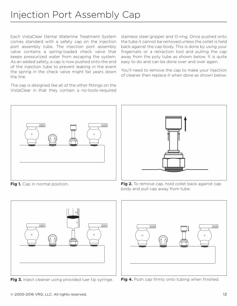
Each VistaClear Dental Waterline Treatment System comes standard with a safety cap on the injection port assembly tube. The injection port assembly valve contains a spring-loaded check valve that keeps pressurized water from escaping the system. As an added safety, a cap is now pushed onto the end of the injection tube to prevent leaking in the event the spring in the check valve might fail years down the line.
The cap is designed like all of the other fittings on the VistaClear in that they contain a no-tools-required
stainless steel gripper and O-ring. Once pushed onto the tube it cannot be removed unless the collet is held back against the cap body. This is done by using your fingernails or a retraction tool and pulling the cap away from the poly tube as shown below. It is quite easy to do and can be done over and over again.
You’ll need to remove the cap to make your injection of cleaner then replace it when done as shown below.
Fig 1. Cap in normal position. Fig 2. To remove cap, hold collet back against cap body and pull cap away from tube.
Fig 3. Inject cleaner using provided luer tip syringe. Fig 4. Push cap firmly onto tubing when finished.
I I I
I I I
I I I
I I I
I I I
I I I
I I I
I I I
I I I
I
5
10
15
20
25

14 VistaClear V1000-28-HP Installation Guide & Owner’s Manual
Maintenance Guide
As with any piece of equipment, proper installation and maintenance of your VistaClear Dental Waterline Treatment System is critical. After installation, the dental waterlines will need to be cleaned to remove any contamination. The installer or service technician should perform the initial line cleaning.
In order to prepare your dental system for use, follow the procedures shown on the following pages. Although other cleaning agents can be used in conjunction with the VistaClear system, we have provided complimentary VistaTab antimicrobial cleaner tablets for your use. You will use these products during the simple maintenance program.
SYSTEM MAINTENANCE SUMMARY
DAILY NONE – Simply discharge each dental appliance for 3 minutes every morning and between patients for 30 seconds as directed by the CDC and Health Canada
QUARTERLY or as needed*
PURGE and CLEAN – Follow the “Line Cleaning” and “Line Rinsing” directions on page 17.
ANNUALLY Change the water filter elements. (Part # R9720 from your dealer.)
Test the VistaCheck dual check valves.
PURGE and CLEAN – Follow the “Line Cleaning” and “Line Rinsing” directions on page 17.
* Treatment should be done if bacteria count is greater than 500 cfu/mL as recommended by the CDC
LINE CLEANSING PROCEDURE:
This should be done immediately after installation and as needed. Note: Always remove hand-pieces, A/W syringe tips and scalers before cleaning lines. Also remember to purge any quick disconnect ports and cup fillers if present.
FOR LINE CLEANSING WITH VISTATABS:
Note: Follow the general line cleansing procedures on page 17.
• After depressurizing the system, remove the plug from the top of the mixing chamber.
• Add one VistaTab to the chamber and return thread the plug back into place.
• Wait at least five minutes for the tab to dissolve.
• Discharge all the dental appliance lines in the operatory and draw out a total of 375 ml then stop and wait 5 minutes to allow VistaTab to work inside the lines.
• Discharge the remaining solution through all the lines until air emerges.
LINE RINSING PROCEDURE:
This should always be performed after a “cleaning” in order to remove debris and residuals from all lines. Follow the directions on page 17.
15© 2000-2016 VRG, LLC. All rights reserved.
System Cleaning Features
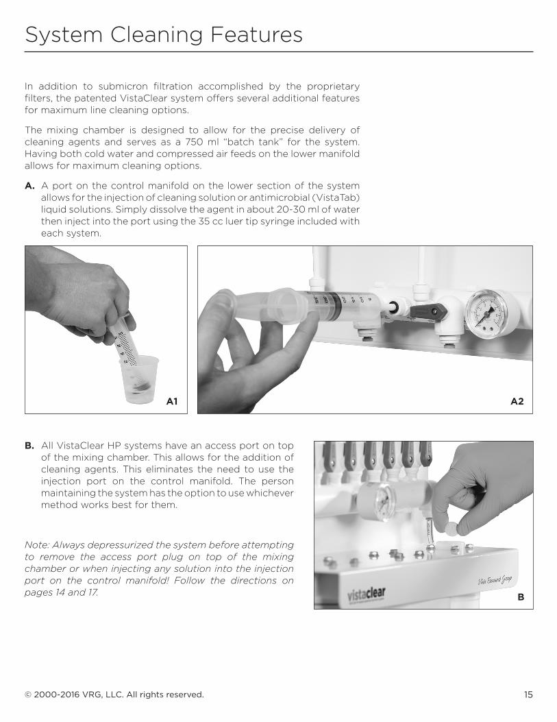
In addition to submicron filtration accomplished by the proprietary filters, the patented VistaClear system offers several additional features for maximum line cleaning options.
The mixing chamber is designed to allow for the precise delivery of cleaning agents and serves as a 750 ml “batch tank” for the system. Having both cold water and compressed air feeds on the lower manifold allows for maximum cleaning options.
A. A port on the control manifold on the lower section of the system allows for the injection of cleaning solution or antimicrobial (VistaTab) liquid solutions. Simply dissolve the agent in about 20-30 ml of water then inject into the port using the 35 cc luer tip syringe included with each system.
A1
B. All VistaClear HP systems have an access port on top of the mixing chamber. This allows for the addition of cleaning agents. This eliminates the need to use the injection port on the control manifold. The person maintaining the system has the option to use whichever method works best for them.
Note: Always depressurized the system before attempting to remove the access port plug on top of the mixing chamber or when injecting any solution into the injection port on the control manifold! Follow the directions on pages 14 and 17.
A2
B
16 VistaClear V1000-28-HP Installation Guide & Owner’s Manual
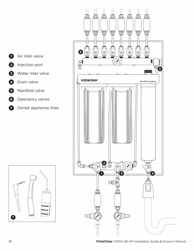
Air inlet valve
Injection port
Water Inlet valve
Drain valve
Manifold valve
Operatory valves
Dental appliance lines
17© 2000-2016 VRG, LLC. All rights reserved.
Cleaning Procedures
A. LINE CLEANSING PROCEDURE
PURGING SYSTEM AND LINESStep 1: Close water inlet valve (3)Step 2: Slowly open drain valve (4)Step 3: Open air valve (1)Step 4: Close drain valve (4) when water stops
running to drainStep 5: Discharge all dental appliance lines (7) in
each operatory into sink, cup or bucket until all water is evacuated and air emerges
Step 6: Close air valve (1)Step 7: Open drain valve (4) to relieve all pressure
from systemStep 8: Close drain valve (4)Step 9: Close all operatory valves (6)
ADDING LINE CLEANERNote: The following will create about 750 ml of cleaning solution. This is usually enough for treating one operatory (a maximum line length per run of 90’ of 1/4” OD copper). After each operatory has been treated a new batch will need to be prepared for the next one, etc. NEVER attempt to inject cleaner if there is pressure on the system!
Step 1: Inject all cleaner concentrate mixture into injection port (2) using syringe provided or drop tab(s) into top port
Step 2: Open water inlet valve (3) to further dilute cleaner and fill mixing chamber with cleaning solution
Step 3: Close water inlet valve (3) when the two gauges read the same pressure and mixing chamber is full
Step 4: Open air inlet valve (1)Step 5: Open one of the valves (6) for the operatory
to be treatedStep 6: Discharge all dental appliance lines (7) in each
operatory into sink, cup or bucket until all air is evacuated and cleaning solution emerges
Step 7: Close air valve (1)Step 8: Open drain valve (4) to relieve all pressure
from system then close drain valve (4)
Repeat Steps 1 – 8 in the section above (maximum one at a time) for all remaining operatories and allow solution to remain in water lines for the proper length of time.
VALVE POSITIONS FOR NORMAL USE
1 – Air Inlet Valve – CLOSED3 – Water Inlet Valve – OPEN4 – Drain Valve – CLOSED5 – Manifold Valve – OPEN 6 – Operatory Valves – OPEN
BYPASS LINE OPERATION
The bypass line is only to be connected in case of emergency or for service purposes. See instructions for system bypassing on page 11.
B. LINE RINSING PROCEDURE
Step 1: Slowly open air valve (1)Step 2: Slowly open drain valve (4) to remove
remaining cleaner from mixing chamberStep 3: Close drain valve (4) when air emerges from
(4)Step 4: Discharge all dental appliance lines (7) in
each operatory into sink, cup or bucket until all cleaner is evacuated and air emerges
Step 5: Close air valve (1)Step 6: Open drain valve (4) to relieve all pressure
from systemStep 7: Close drain valve (4)Step 8: Open water inlet valve (3) to fill mixing
chamberStep 9: Discharge all dental appliance lines (7) in
each operatory into sink or cup until all air is evacuated and clear water emerges. Rinse each line for 10 seconds. The system is now ready for use!
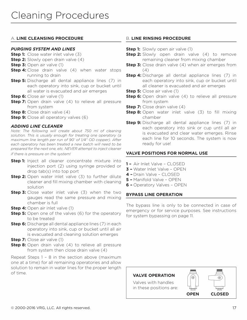
VALVE OPERATION
Valves with handles in these positions are:
OPEN CLOSED
18 VistaClear V1000-28-HP Installation Guide & Owner’s Manual
Replacing VistaClear HP Filters
1. Turn off the cold-water inlet on the lower VistaClear manifold to stop water flow to the system.
2. Open the drain valve on the lower end of the mixing chamber to relieve pressure from the system.
3. Open the air valve for a few seconds to purge any remaining water from the mixing chamber. Once only air is emerging from the drain valve, turn OFF the air valve.
4. When the gauges on the system register “0,” use the supplied sump wrench to remove the filter sumps and filters. Support the system by holding the filter manifold while loosening the filter sumps.
5. Remove and discard the expired filters in the normal trash.
6. Wash and rinse each of the filter sumps with clean water. Wipe the center section of each filter cap with an alcohol wipe to clean.
7. Replace the “O” ring in each sump with the pre-lubricated “O” ring that is supplied with each replacement filter. Discard old “O” rings.
8. Transfer the filter serial numbers from the outside of each replacement filter to the permanent record table on the back page of the VistaClear manual along with the date replaced. BE CAREFUL! Do not drop! The filter elements are fragile.
9. Completely remove the labels and plastic wrap from both filters. Try not to touch the surface of the ceramic or wear clean gloves. Check for any cracks in the surface of the filter elements. Do NOT install if cracks are discovered! Contact the factory for help.
10. Carefully lower the filters into their respective filter sumps, making certain the open-end cap is “up” in the housing.
11. Make certain the filters are centered within the housing, then carefully thread the sumps onto their respective filter caps on the manifold. Do not cross thread. Firmly tighten the sumps while supporting the metal manifold. Hand-tighten only!
12. After both sumps have been tightened, turn on the water supply by turning the blue handle on the water valve on the lower manifold. Water will start to flow into the filter housings.
13. Open the drain valve on the bottom of the mixing chamber, allowing air to be purged from the system. Once water has filled both filter sumps, water from the filters will begin to flow to the drain. Allow the water to run to the drain for two (2) minutes to flush filters.
14. Close the drain valve on the mixing chamber and check the system for any leaks. If a leak is detected, immediately turn off the water supply and open the drain valve on the mixing chamber to relieve the water pressure. Attend to the leak then repeat the steps to check for additional leaks.
15. If the system and attached plumbing fittings are leak-free and the dental units in each operatory have been attached to the respective dedicated feed lines from the VistaClear system, open each of the individual valves on the top manifold and water will flow to each operatory. Check for leaks at the operatory end of each line.
16. If all connections are leak-free, begin a complete system purge (as described in the VistaClear manual) to ensure all lines are clean and ready for use.
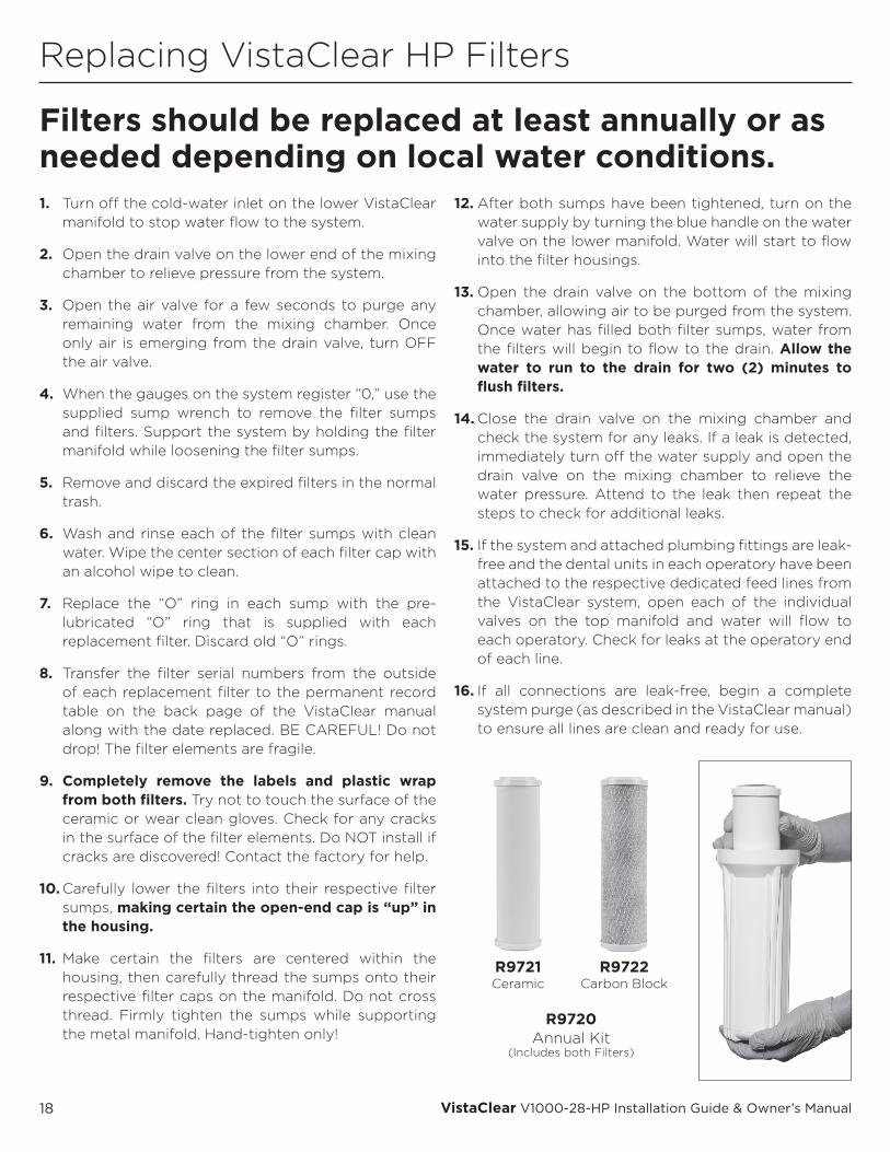
Filters should be replaced at least annually or as needed depending on local water conditions.
R9721 Ceramic
R9722 Carbon Block
R9720 Annual Kit
(Includes both Filters)
19© 2000-2016 VRG, LLC. All rights reserved.
VistaClear Limited Warranty
During the time period and subject to the conditions hereinafter set forth, Vista Research Group, LLC (VRG) will repair or replace to the original user any portion of a VRG product which proves defective due to defective materials or workmanship of VRG. Contact your nearest authorized VRG distributor/dealer for warranty service. At all times VRG shall have and possess the sole right and option to determine whether to repair or replace defective equipment, parts, or components. Damage due to conditions beyond the control of VRG is NOT COVERED BY THIS WARRANTY. (Contact parcel or freight company for claims on freight damaged in transit)
WARRANTY PERIOD: VRG shall warrant its dental waterline treatment systems and other systems for a period of two (2) years from the date of installation, or thirty (30) months from the date of manufacture, which ever comes first. Treatment filtration elements subject to varying types of water conditions are not warranted for performance due to fouling by local water conditions but are warranted for defects in materials and workmanship.
LABOR, ETC., COSTS: VRG shall IN NO EVENT be responsible or liable for the cost of field labor or other charges incurred by any customer in removing and/or re-affixing any VRG product, part or component thereof.
THIS WARRANTY WILL NOT APPLY: (a) To defects or malfunctions resulting from failure to properly install, operate or maintain the unit in accordance with printed instructions provided; (b) to failures resulting from abuse, accident or negligence; (c) to normal maintenance services and the parts used in connection with such service; (d) to units which are not installed in accordance with applicable local codes, ordinances and good trade practices; (e) if the unit is moved from its original installation location, or; (f) if the unit is used for purposes other than for what it was designed and manufactured.
RETURN OF REPLACED COMPONENTS: Any item to be replaced under this Warranty must be returned to Vista Research Group, LLC (VRG) in Ashland, Ohio, or such other place as VRG may designate, freight prepaid. Write to the address listed below for a return authorization and the physical address to which items should returned for warranty attention.
PRODUCT IMPROVEMENTS: VRG reserves the right to change or improve its products or any portions thereof without being obliged to provide such change or improvement of units sold and/or shipped prior to such change or improvement.
WARRANTY EXCLUSIONS: As to any specific VRG product, after the expiration of the time period of the warranty applicable thereto as set forth under the heading “Warranty Period” above, THERE WILL BE NO WARRANTIES, INCLUDING ANY IMPLIED WARRANTIES OF MERCHANTABILITY OR FITNESS FOR ANY PARTICULAR PURPOSE.
Some states do not allow limitations on how long an implied warranty lasts, so the above limitations may not apply to you. No warranties or representations at any time made by any representative of VRG shall vary or expand the provisions hereof.
LIABILITY LIMITATION: IN NO EVENT SHALL VRG BE LIABLE OR RESPONSIBLE FOR CONSEQUENTIAL, INCIDENTAL OR SPECIAL DAMAGES RESULTING FROM OR RELATED IN ANY MANNER TO ANY VRG PRODUCT OR PARTS THEREOF.
Some states do not allow the exclusion of limitation of incidental or consequential damages, so the above limitation or exclusion may not apply to you.
This Warranty gives you specific legal rights and you may also have other rights which vary from state to state.
For your warranty protection (Magnason-Moss Warranty Act), the warranty card, if provided, should be completed and returned to VRG within ten (10) days of installation. In the absence or other suitable proof of installation date, the effective date of this warranty will be based upon the date of manufacture plus one hundred eighty (180) days.
DIRECT ALL NOTICES, ETC. TO:Service DepartmentVista Research Group, LLCP.O. Box 321Ashland, Ohio 44805-0321
20 VistaClear V1000-28-HP Installation Guide & Owner’s Manual
Backflow Prevention
ANNUAL BACKFLOW PREVENTER VALVE TESTING:
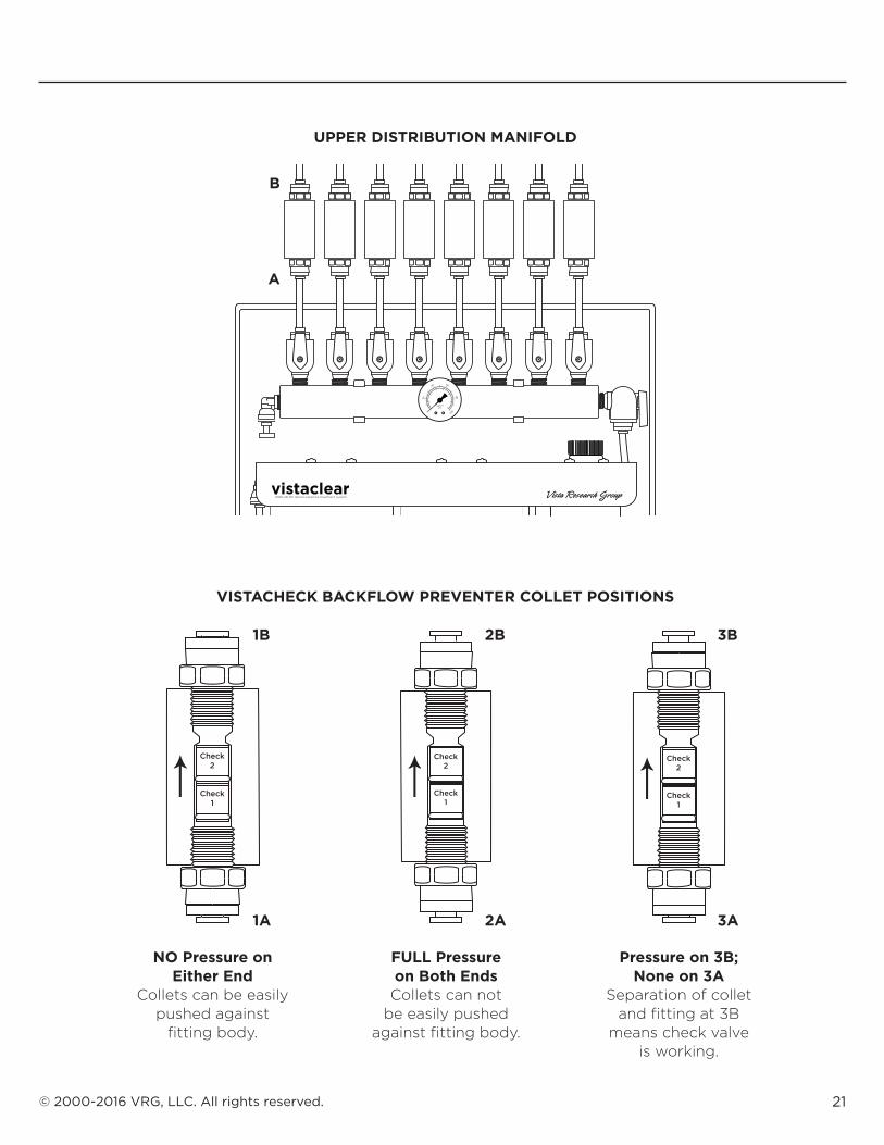
All VistaCheck backflow preventer valves downstream of the Distribution Manifold on the system should be checked once per year to make certain they are working properly. Follow these steps to perform this simple but important testing procedure. This testing procedure will not expose the system to outside contamination.
1. Start with the system in the normal service position. This means that the water inlet valve on the lower manifold is open, the air inlet valve is closed, the drain valve is closed and all valves leading to operatories are open. The pressure gauges should be registering readings approximately 40 psi in the service position if regulators are in place. If regulators are not being used, the pressure readings will be higher. In the service position with all operatory valve open, there will be pressure throughout the entire system.
2. Close the water inlet valve on the lower Control Manifold and open the drain valve on the Mixing Chamber to relieve all system pressure and allow water from the Chamber to run to drain.
3. Examine the VistaCheck backflow preventer valves above the upper Distribution Manifold. They are designed with collets on each end that move away from the fitting body when the fitting is under pressure. When there is no pressure in the fitting, the collets can be easily pushed against the fitting body. Please see the diagrams on the opposite page that shows the location of the VistaCheck backflow preventer valves relative to the Distribution Manifold and the position of collets under various pressure conditions.
4. With the drain valve still in the open position and using fingertips, attempt to push the collet on the outlet side of the VistaCheck (position B) back against the fitting body.
• If there is strong resistance or the collet cannot be moved, this indicates that the check valve is working properly since pressure from the line running to the opertory is still present.
• If the collet can be pushed back against the fitting body at position B, that check valve is not working properly and should be replaced immediately. Repeat this test procedure on each VistaCheck to ensure pressure is being held in each operatory distribution line.
5. To return to normal operating position, close the drain valve on the Mixing Chamber and open the water inlet valve on the lower Control Manifold. Pressure should register on both gauges and the system is ready for use.
NOTE: If either of the filters were changed during the same time period as the backflow test or if any of the VistaCheck backflow preventer valves were removed or replaced, be certain to perform a full system cleaning since the lines and components will have been exposed to possible bacterial contamination.
Test VistaChecks annually. Record test information in tables on pages 22 & 23.
21© 2000-2016 VRG, LLC. All rights reserved.
NO Pressure on Either End
Collets can be easily pushed against
fitting body.
FULL Pressure on Both EndsCollets can not
be easily pushed against fitting body.
Pressure on 3B; None on 3A
Separation of collet and fitting at 3B
means check valve is working.
1B
B
A
2B 3B
1A 2A 3A
UPPER DISTRIBUTION MANIFOLD
VISTACHECK BACKFLOW PREVENTER COLLET POSITIONS
Check2
Check1
Check2
Check1
Check2
Check1
22 VistaClear V1000-28-HP Installation Guide & Owner’s Manual
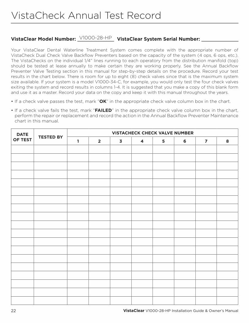
VistaCheck Annual Test Record
VistaClear Model Number: VistaClear System Serial Number:
Your VistaClear Dental Waterline Treatment System comes complete with the appropriate number of VistaCheck Dual Check Valve Backflow Preventers based on the capacity of the system (4 ops, 6 ops, etc.). The VistaChecks on the individual 1/4” lines running to each operatory from the distribution manifold (top) should be tested at lease annually to make certain they are working properly. See the Annual Backflow Preventer Valve Testing section in this manual for step-by-step details on the procedure. Record your test results in the chart below. There is room for up to eight (8) check valves since that is the maximum system size available. If your system is a model V1000-34-C, for example, you would only test the four check valves exiting the system and record results in columns 1-4. It is suggested that you make a copy of this blank form and use it as a master. Record your data on the copy and keep it with this manual throughout the years.
• If a check valve passes the test, mark “OK” in the appropriate check valve column box in the chart.
• If a check valve fails the test, mark “FAILED” in the appropriate check valve column box in the chart, perform the repair or replacement and record the action in the Annual Backflow Preventer Maintenance chart in this manual.
V1000-28-HP
DATE OF TEST TESTED BY
VISTACHECK CHECK VALVE NUMBER
1 2 3 4 5 6 7 8
23© 2000-2016 VRG, LLC. All rights reserved.
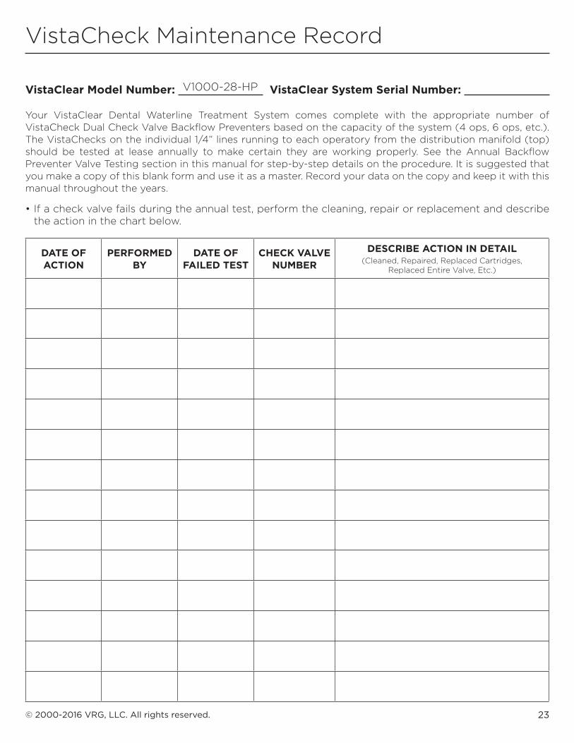
VistaClear Model Number: VistaClear System Serial Number:
Your VistaClear Dental Waterline Treatment System comes complete with the appropriate number of VistaCheck Dual Check Valve Backflow Preventers based on the capacity of the system (4 ops, 6 ops, etc.). The VistaChecks on the individual 1/4” lines running to each operatory from the distribution manifold (top) should be tested at lease annually to make certain they are working properly. See the Annual Backflow Preventer Valve Testing section in this manual for step-by-step details on the procedure. It is suggested that you make a copy of this blank form and use it as a master. Record your data on the copy and keep it with this manual throughout the years.
• If a check valve fails during the annual test, perform the cleaning, repair or replacement and describe the action in the chart below.
V1000-28-HP
DATE OF ACTION
PERFORMED BY
DATE OF FAILED TEST
CHECK VALVE NUMBER
DESCRIBE ACTION IN DETAIL(Cleaned, Repaired, Replaced Cartridges,
Replaced Entire Valve, Etc.)
VistaCheck Maintenance Record
HP-09222016
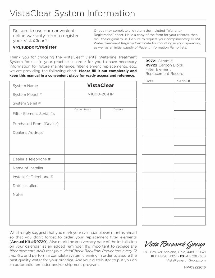
VistaClear System Information
We strongly suggest that you mark your calendar eleven months ahead so that you don’t forget to order your replacement filter elements (Annual Kit #R9720). Also mark the anniversary date of the installation on your calendar as an added reminder. It’s important to replace the filter elements AND test your VistaCheck Backflow Preventers every 12 months and perform a complete system cleaning in order to assure the best quality water for your practice. Ask your distributor to put you on an automatic reminder and/or shipment program.
P.O. Box 321, Ashland, Ohio, 44805-0321PH: 419.281.3927 • FX: 419.281.7380
VistaResearchGroup.com
Thank you for choosing the VistaClear™ Dental Waterline Treatment System for use in your practice! In order for you to have necessary information for future maintenance, filter element replacements, etc., we are providing the following chart. Please fill it out completely and keep this manual in a convenient place for ready access and reference.
System Name VistaClear
System Model # V1000-28-HP
System Serial #
Filter Element Serial #sCarbon Block Ceramic
Purchased From (Dealer)
Dealer’s Address
Dealer’s Telephone #
Name of Installer
Installer’s Telephone #
Date Installed
Notes
R9721 Ceramic R9722 Carbon Block Filter Element Replacement Record
Date Serial #
Be sure to use our convenient online warranty form to register your VistaClear™!
vrg.support/register
Or you may complete and return the included “Warranty Registration” sheet. Make a copy of the form for your records, then mail the original to us. Be sure to request your complimentary DUWL Water Treatment Registry Certificate for mounting in your operatory, as well as an initial supply of Patient Information Pamphlets.