Installation Guide KarrierPanel Wall System · This installation guide is only to be used in...
112
Installation Guide KarrierPanel ™ Wall System Insulated Panels North America
Transcript of Installation Guide KarrierPanel Wall System · This installation guide is only to be used in...

Installation Guide KarrierPanel™ Wall System
Insulated Panels North America
2
DisclaimerThis installation guide is only to be used in conjunction with panel installation drawings and Kingspan recommended details. Details shown in
project shop drawings take precedence over any similar information in this manual. Shop drawings may be prepared either by Kingspan or by the
panel contractor. Kingspan’s Technical Service Department is available to assist the panel
contractor in the review of shop drawings.
This guide is intended to provide the panel contractor with recommended methods, procedures
and guidelines for the installation of the KarrierPanel™ system for commercial and architectural
applications. Information presented is accurate but may not cover all situations, building conditions
and/or details of your specific project. Consult Kingspan Technical Services where this guide does
not cover your unique construction requirements. It is the sole responsibility of the project engineer
and panel installer to ensure specified air and weather tightness of a building by good design and
workmanship in accordance with approved drawings using only the appropriate type of sealants.
It is the sole responsibility of the owner’s representative and panel installer to maintain quality
workmanship in accordance with approved shop drawings to ensure the best performance of the wall system.
Kingspan recommends installers read this document fully before receiving the panels on the job site. Installation classes are
available through Kingspan’s Technical Services Department. Please call 1-888-882-5862 for more information.
Follow the architect’s approved shop drawings and engineering calculations for your project specific fastening patterns. The engineer of record
is responsible for verifying applicable design loads and panel fastening requirements.
All safety procedures, including adequate fall protection, are the responsibility of the panel contractor.
KarrierPanel™ Wall System
Installation Guide
IMPORTANT!Please read all information related to your project before receiving materials at the job site and before starting the installation.

3
Contents
1: Introduction 4
2: Technical Information 5
3: Inspection Upon Delivery 6
4: Panel Handling 7
5: Panel Storage on Site 12
6: Handling and Storage of Auxillary Items and Accessories 13
7: Removal of Protective Film 13
8: Structural Alignment 14
9: Panel Cutting Procedures 15
10: Panel Sealant Placement 17
11: Panel Touch-Up Paint 18
12: Panel Cleaning and Maintenance 18
13: Vertical Installation 19
14: Vertical Construction Details 37
15: Horizontal Installation 46
16: Horizontal Construction Details 61
17: Horizontal Installation: Brick 78
18: Horizontal Construction Details: Brick 100
19: Fastener Information 107
20: Materials, Tools and Hardware 110
Scan here to connect to our digital brochure for updates

4
1: Introduction
1.1 FeaturesThe KarrierPanel™ product range is suitable for large scale
commercial and architectural projects and is available in either
horizontal or vertical applications.
1 Single component wall panels provide a robust long lasting
weather barrier, insulating core and interior vapor barrier
all-in-one.
2 Polyisocyanurate foam core retains original insulating value
over time.
3 Unique KarrierRail™ replaces the panel clip system and does not
penetrate the air vapor barrier.
4 Panels are lightweight, easy to install under most weather
conditions.
5 KarrierPanel™ is adaptable to a wide variety of rainscreen profiles.
(Where brick facade is used, Kingspan’s brick tie is utilized in lieu
of the KarrierRail™).
6 Panels are available in lengths of up to 52’ to minimize the
number of stack joints required.
7 Accessory items including metal flashings are available (contact
Kingspan for more information).
1.2 Insulation ValuesKarrierPanel™ panels are available in the following configurations:
� 2” panel thickness � 4” panel thickness� 2.5” panel thickness � 5” panel thickness� 3” panel thickness � 6” panel thickness
KarrierPanel™ panels offer the building designer R values of
approximately 7.5 per inch, as well as the ability to balance initial
cost versus long-term energy savings.
To complete the wall system a full range of integrated accessories
including attachment clips, metal trims and aluminum extrusions are
available.
Welcome to Kingspan, global leaders in the design and manufacture of insulated metal panels. Insulated panels serve as energy efficient, state-of-the-art alternative to traditional construction. This document serves as installation guidelines for the KarrierPanel™ wall system.
1.3 WarrantiesKingspan can furnish various performance warranties as required by
project specifications. The items covered by these warranties include
weathertightness, corrosion, structural performance and finish
performance.
Weathertight warranties require the use of Kingspan Authorized
Installers. In addition, these projects require several jobsite
inspections, so be sure to schedule inspections in advance.
Kingspan requires that all specifications and shop drawings are
reviewed prior to warranty issuance. In addition, warranties are
limited to materials supplied by Kingspan, and are not issued until full
payment for all services and material provided is received.
Contact Kingspan Customer Service for more information on our
warranty programs.
1.4 Installer QualificationsKingspan recommends that our panels are installed under the direct
supervision of an experienced installation contractor trained in the
proper application of our products. Please contact Kingspan at
1-888-882-5862 for information regarding our Authorized Installer
training programs.
2”-6
”
Shadowline (KS42SL) Panel
Exterior face
Interior face
42” Coverage (36”, 30” & 24” optional)
Shadowline
Shadowline

5
2: Technical Information
KarrierPanel™ wall panels have been thoroughly evaluated and tested by independent third party laboratories (UL, ULC) to determine all aspects of their performance.
The results of these tests, in combination with our comprehensive engineering analysis, enable us to provide design assistance
for nearly every project. This includes complete panel analysis of wind, live, seismic and thermal loading as well as allowable spans,
deflection and recommended fastening.
2.1 DeflectionCurrent industry standards for insulated metal wall panels specify
a deflection of L/180. The project designer and/or engineer of
record should always check the applicable code(s) for deflection
limits. For deflection limits other than L/180, please contact
Kingspan Technical Services for evaluation.
2.2 ComplianceKingspan panels are in compliance with FM 4881 Approval
Standard for Exterior Wall Construction.
2.3 Panel DiaphragmInsulated panels should NOT be relied upon to provide significant
diaphragm strength. Instead, cross bracing (cables, rods, angle
iron etc.) should be used to provide diaphragm. Insufficient
bracing for the walls may result in damage to the panels, and will
void the panel warranty.
2.4 SeismicKingspan wall panels are mechanically attached on one side only,
with the other side free to slide along the tongue and groove
joint configuration. In addition to this built-in slip joint design, the
panels are very light (approx. 3-4 psf). As a result, they are ideal for
use in seismically sensitive projects.
2.5 Fire PerformanceKingspan panels have been thoroughly evaluated by Factory
Mutual, UL and ULC and are covered under various product
approval listings.
2.6 Air and Water InfiltrationAir and Water Infiltration testing has been successfully conducted
on the KS Series panels in accordance with ASTM E-283/331.
For more information on any of the above items,
please contact Kingspan Technical Services:
Deland, FL – 386-626-6789
Modesto, CA – 209-531-9091
Caledon, Ontario (Canada) – 905-951-5600
For installation assistance:
For engineering assistance:
The information contained in this guide is thought to be reliable
and correct, but is subject to change without notice.
6
3: Inspection Upon Delivery
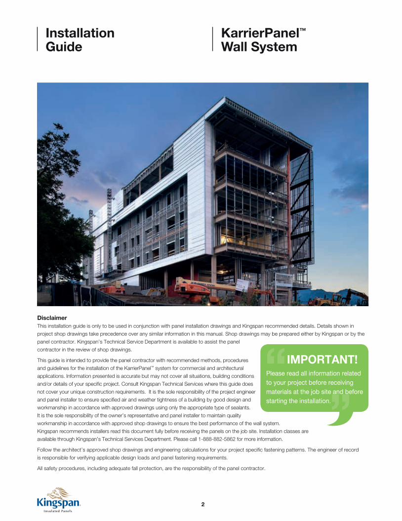
3.1Panels are carefully packaged in large shrink-wrapped bundles,
then shipped on flat bed trailers to the construction site. When a
shipment is received, check all items against the shipping document
for quantities, dimensions, colors, transit damage, etc. Document any
shortage of panels and accessories or panel damage on the bill of
lading and have it signed by the driver. It is the receiver’s responsibility
to make any damage claims immediately.
Please note that although every effort is made to prevent shipping
damage, Kingspan is not responsible for damage which may occur
during transportation, delivery, storage or on-site handling.
7
4: Panel Handling
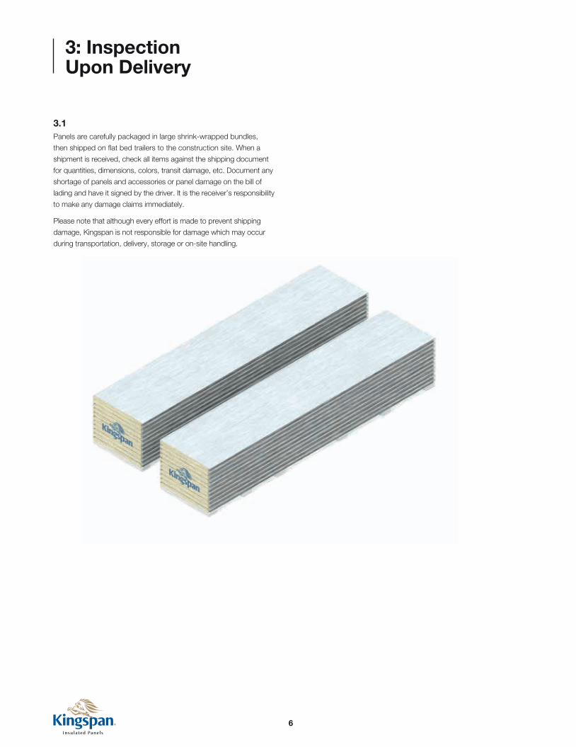
Fig. 4.1a
Fig. 4.1b
4.1 Panels Handled by Forklift4.1.1 The recommended loading/unloading method for bundles less
than or equal to 30’ is to use a single forklift with widely spaced forks
placed under the center of the bundle as shown in Figure 4.1a.
Panel bundles over 30’ in length may be moved by using two
forklifts spaced equally along the length of the bundle as shown in
Figure 4.1b. Inspect travel route to assure a reasonably level and
compacted surface free of ruts and excavations.
4.1.2 To prevent panels from damage while lifting,
carefully pick up bundles one at a time.
Lifting point at center of panel bundle
Protective plywood (not by Kingspan)
C LMax 3
0’-0” (9.14m)
8
Wood spreaders (see Fig 4.3)
Nylon straps
Polyurethane foam blocks
3/8” (9.5mm)
3/8” (9.5mm)
11/2” (38mm)
2” (50mm)
Wood spreader
2” (50mm)43/8” (110mm)
Max 30’-0” (9
.14m)
Bundle width +4” (100mm)
Bundle width
4: Panel Handling
Wood spreader
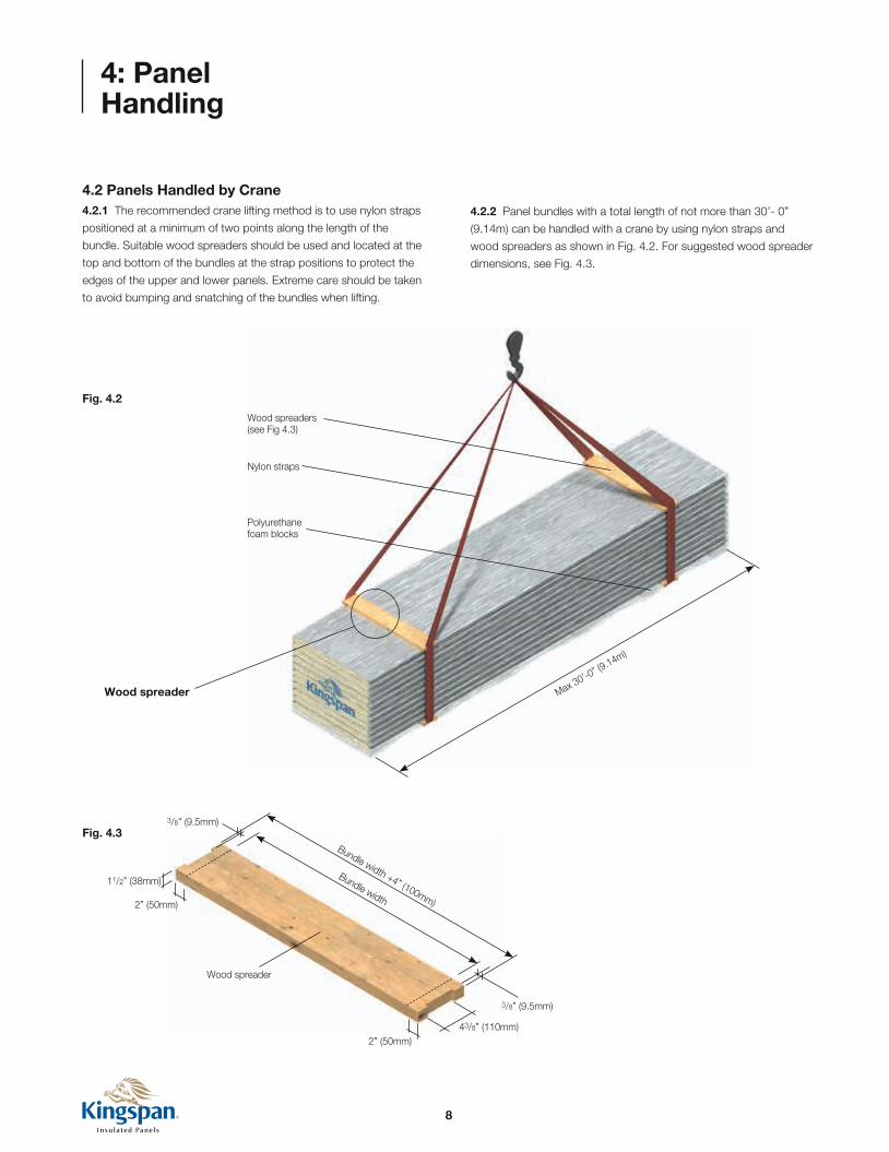
4.2 Panels Handled by Crane4.2.1 The recommended crane lifting method is to use nylon straps
positioned at a minimum of two points along the length of the
bundle. Suitable wood spreaders should be used and located at the
top and bottom of the bundles at the strap positions to protect the
edges of the upper and lower panels. Extreme care should be taken
to avoid bumping and snatching of the bundles when lifting.
4.2.2 Panel bundles with a total length of not more than 30’- 0”
(9.14m) can be handled with a crane by using nylon straps and
wood spreaders as shown in Fig. 4.2. For suggested wood spreader
dimensions, see Fig. 4.3.
Fig. 4.2
Fig. 4.3
9
4: Panel Handling
4.3 Handling Individual Panels
Fig. 4.4
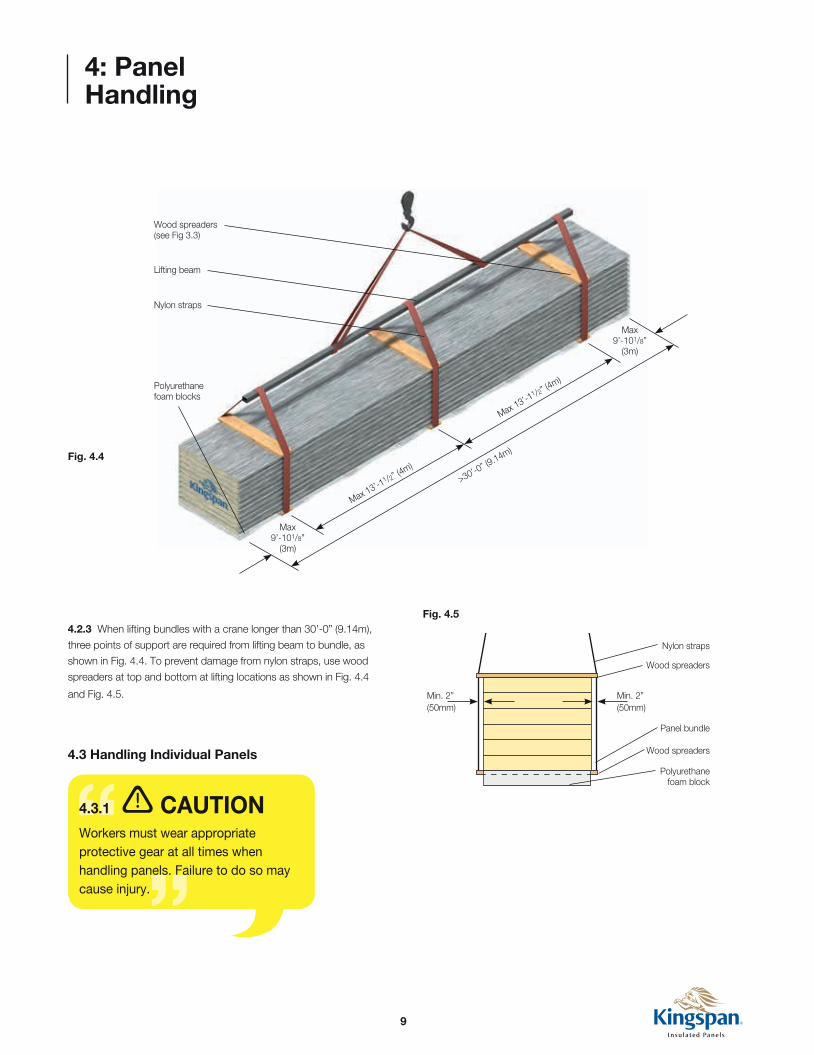
Fig. 4.54.2.3 When lifting bundles with a crane longer than 30’-0” (9.14m),
three points of support are required from lifting beam to bundle, as
shown in Fig. 4.4. To prevent damage from nylon straps, use wood
spreaders at top and bottom at lifting locations as shown in Fig. 4.4
and Fig. 4.5.
Wood spreaders (see Fig 3.3)
Lifting beam
Nylon straps
Polyurethane foam blocks
Min. 2” (50mm)
Min. 2” (50mm)
Nylon straps
Wood spreaders
Panel bundle
Wood spreaders
Polyurethane foam block
>30’-0” (9.14m)
Max 13’-1
1 /2” (4m)
Max 9’-101/8”
(3m)
Max 9’-101/8”
(3m)
Max 13’-1
1 /2” (4m)
4.3.1 CAUTIONWorkers must wear appropriate protective gear at all times when handling panels. Failure to do so may cause injury.

10
7
3
NOTEPanels exposed to direct sunlight may exhibit thermal bow, which can hinder panel engagement. This can be corrected by either placing the panels in a shaded area, or by flipping the panels over exposing the cool side of the panel to the sunlight for approximately 15 minutes.
Panels are to be fastened at every support unless otherwise indicated on the shop drawings. Fastener requirements at each clip are based on design loads. Refer to the shop drawings for the correct fastening, or contact Kingspan Technical Services for assistance.
Sun heats top face causing bow
Bowed panel
Opened panel bundle
Reverse panel to allow for even warming
Bowed panel
Opened panel bundle
4: Panel Handling
Correct and Incorrect Panel Handling
Thermal Bowing
4.3.2 CAUTIONIndividual panels should never be moved in a flat position as excessive flexing may result. Excessive flexing ruptures a panel’s core, permanently distorts the facings and may lead to thermal blistering. When moving a panel, it must be turned on its edge first, then supported at each end with as many men as necessary to safely handle.

11
4: Panel Handling
4.3.3 CAUTIONTo prevent joint damage and possible delamination, never lift a panel from the top sheet only. Lift from underneath the entire panel.
4.3.4 CAUTIONNever drag a panel from a bundle or across other surfaces. It will scratch and damage the panel coating/finish. Always lift panels when removing from bundle.
4.4 Lifting Panels Using Vacuum EquipmentPanel installation time can often be reduced by using vacuum lifting
equipment. The following items need to be verified by the equipment
supplier prior to use: lifting equipment must be adequate for panel
lengths and weights, and provide sufficient mobility and reach for the
project conditions.
Vacuum heads (cups) must be suitable to safely lift panels with
profiled and/or embossed surfaces. Fluted profiles may require
specific vacuum heads.
Kingspan recommends using Rotaboy and Cladboy vacuum
lifting systems.
For equipment parameters and availability, please contact
AutoMak Assembly Inc.:
1-219-759-2300

12
5: Panel Storage On Site
5.1Site must have adequate storage space to receive and store the
panel bundles. This space must be level, firm, clean and free from
standing water. Bundles should be stored in a dry condition, with
one end slightly elevated to facilitate moisture drainage.
5.2Panels should be inspected upon delivery for presence of moisture.
If moisture is present, bundles should be slit open immediately to
allow ventilation and drainage.
5.3If panels are to be used immediately, bundles should be placed at
pre-planned strategic locations around the building perimeter,
as close as possible to the specific work areas. Review installation
shop drawings to determine the best locations.
5.4Panels in opened bundles should be covered by a plastic sheet or
tarp at the end of the working day. The covering and bundles must
be securely fastened to prevent wind damage (see Figure 5.1).
5.5When handling panels and/or panel bundles, ropes, steel cables or
chains must not be used.
5.6Avoid outdoor storing for longer than 60 days. Moisture between
panels can cause corrosion or staining. Staining of any kind is not
considered to be a cause for rejection.
5.7If panels are not to be used immediately, then they should be stored
under a temporary shelter with the plastic removed from the top and
sides of the bundles. Recover the bundles with a protective tarp and
adequately secure both tarp and panels to prevent wind damage
(see Figure 5.1).
NOTEWhen stacking bundles (maximum two high) limit storage time to 30 days to prevent panel damage.
Fig. 5.2
2% slope for water run-off
Fig. 5.1

13
6: Handling and Storage of Auxillary Items and Accessories
7: Removal of Protective Film
6.1Care should be taken during unloading and storage to prevent
damage to small items, ie. trims fasteners, clips, sealants, etc.
6.2Cover all pallet crates or boxes to protect materials from weather
but allow for ventilation to prevent condensation. Temperature
sensitive items such as butyl tapes and sealants should be stored
under controlled conditions to maintain suitable application
characteristics.
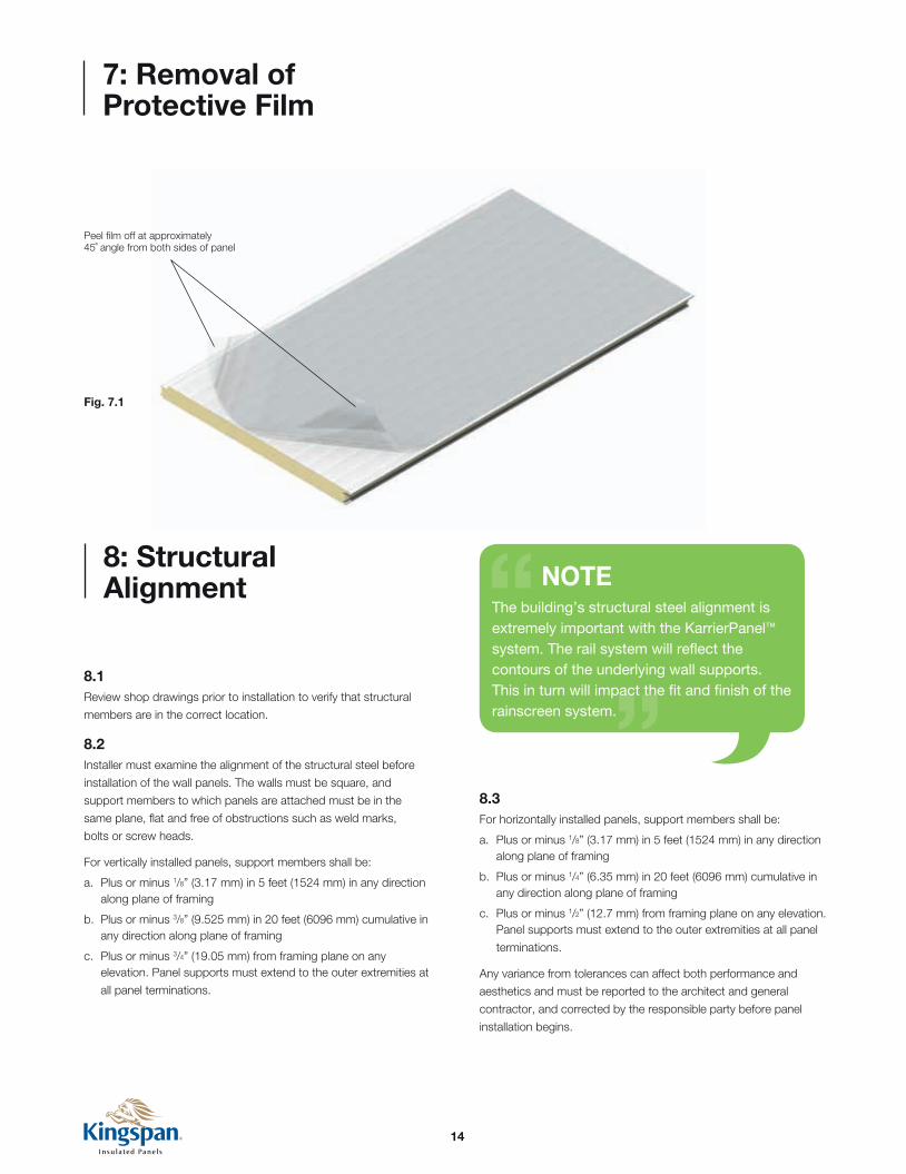
It is recommended to remove protective film as panels are
installed. Film on installed panels should be removed by the end
of each day.
Loosen film along both edges, grab corners together and peel off
while walking down length of panel (see Fig. 7.1).
If adhesive residue remains on panel surfaces after the protective
film is removed, panels may be cleaned with a rag soaked in 409,
SFR or equivalent. After cleaning, rinse thoroughly. For safety,
provide adequate eye and skin protection, ventilation and follow
all other manufacturer’s instructions.
NOTEIf panels will not be installed within 60 days of receipt, the bundles should be unstacked and the protective film removed from each panel. Carefully restack the panels and protect from the elements. Failure to remove the film within this time period may result in excessive film adhesion and breakdown of the plastic, making removal extremely difficult. In addition, failure to remove the film as instructed may result in a buildup of adhesive residue.
Kingspan is not responsible for either of these conditions. Film removal and panel cleaning is the responsibility of the installation contractor.
14
7: Removal of Protective Film
8: Structural Alignment
Peel film off at approximately 45˚ angle from both sides of panel
Fig. 7.1
8.1Review shop drawings prior to installation to verify that structural
members are in the correct location.
8.2Installer must examine the alignment of the structural steel before
installation of the wall panels. The walls must be square, and
support members to which panels are attached must be in the
same plane, flat and free of obstructions such as weld marks,
bolts or screw heads.
For vertically installed panels, support members shall be:
a. Plus or minus 1/8” (3.17 mm) in 5 feet (1524 mm) in any direction along plane of framing
b. Plus or minus 3/8” (9.525 mm) in 20 feet (6096 mm) cumulative in any direction along plane of framing
c. Plus or minus 3/4” (19.05 mm) from framing plane on any elevation. Panel supports must extend to the outer extremities at
all panel terminations.
8.3For horizontally installed panels, support members shall be:
a. Plus or minus 1/8” (3.17 mm) in 5 feet (1524 mm) in any direction along plane of framing
b. Plus or minus 1/4” (6.35 mm) in 20 feet (6096 mm) cumulative in any direction along plane of framing
c. Plus or minus 1/2” (12.7 mm) from framing plane on any elevation. Panel supports must extend to the outer extremities at all panel
terminations.
Any variance from tolerances can affect both performance and
aesthetics and must be reported to the architect and general
contractor, and corrected by the responsible party before panel
installation begins.
NOTEThe building’s structural steel alignment is extremely important with the KarrierPanel™ system. The rail system will reflect the contours of the underlying wall supports. This in turn will impact the fit and finish of the rainscreen system.

15
9: Panel Cutting Procedures
9.1Personnel working with panel cutting equipment should wear
respiratory and eye protection at all times.
9.2Panel cutting should take place prior to panel installation
whenever possible.
9.3Use the appropriate cutting tools with extreme care to avoid panel
delamination. Do not use a cutting disk, torch, and other high heat
producing methods for cutting. Hot filings may damage the painted
surface of the panel.
Kingspan recommends use of a circular saw with a fine tooth
carbide tip blade. A band saw with a suitable metal cutting blade
may also be used.
NOTEDo not use an electric grinder, reciprocating saw, or any tool that may cause serious delamination.
9.4For small penetrations, a Dremel type router may be used to cut
each face of the panel, and a serrated bread knife may be used to
cut the foam core.
9.5Power snips, nibblers or hand snips may be used to cut trims
and flashings.

16
9: Panel Cutting Procedures
9.6Step 1: Mark the cut line on the interior and exterior panel facings.
Step 2: Leave protective film in place during cutting. If film has
already been removed, apply masking tape adjacent to the
area to be cut.
Step 3: Recheck measurements and proceed with cutting
operation. Cut the interior face of the panel and about 1/4 of
the foam thickness using a circular saw with a fine toothed
carbide tipped blade. Then carefully turn panel over and
cut the exterior face and the remainder of the foam.
Step 4: For panels located at framed opening locations where 50%
or more of the panel width is removed, cut interior face and
foam to a depth of approx. 1/4”. Flip panel over and
cut exterior face and foam to a depth of approx. 1/4”.
Then cut through the joints on the edge of the panel that
is to be removed for the opening. Lift the panel into place,
secure with fasteners as required, then use a serrated
bread knife to fully cut through the foam and remove the
cut section of panel.
Step 5: File or sand off any burrs or rough spots at the cut line.
Sweep off all metal shavings etc. The panel is now ready
to be erected.
Fig. 9.1

17
10: Panel Sealant Placement
10.1Apply butyl sealant to interior female joint to ensure proper vapor
barrier. Joint should be dry and clean before applying sealant.
Fill female pocket approximately 1/2 to 3/4 full.
Add/delete as necessary during panel installation to
maintain proper panel seal.
Fig. 10.1:
Applying sealant on site
Fig. 10.1a NOTEIn extreme cold weather locations, it may be advisable to caulk both interior and exterior joints. It is also advisable to keep sealants in a warming bin until ready for use to ensure proper viscosity. Contact Kingspan Technical Services for more information.
NOTEPull (not push) caulk tube along length of side joint for more uniform sealant bead.

18
12.6Caulking compounds, oil, grease, tars, wax and similar substances
can be removed by wiping with a cloth soaked with WD-40
lubricant or mineral spirits. Test on an inconspicuous area first.
Do not rub excessively or damage to the finish may result.
Wipe only contaminated areas and follow with detergent cleaning
and thorough rinsing.
12.7To remove oxidation and tough stains, use a household cleaner
recommended for use on porcelain skins and bathtubs. This should
be followed with a thorough rinsing. Wire brushing or any abrasive
material may damage the painted surface and should not be used.
12.8Contact Kingspan Customer Service to receive a copy of the
complete Kingspan Panel Maintenance Manual.
11: Panel Touch-up Paint
12: Panel Cleaning and Maintenance
11.1The panel erector is to touch up all exposed field cut edges with
touch up paint. Contact Kingspan Customer Service for information
on appropriate touch up paint.
12.1Proper installation and maintenance are extremely important in
obtaining the very best service and appearance from pre-painted
metal insulated panels.
12.2All dirt, oil, grease, fingerprints, metal filings or other contaminants
should be removed to assure proper service life of the paint system.
The installer should wipe-down the panels as they are erected.
12.3Dirt pickup may cause apparent discoloration of the paint after
prolonged exposure. Slight chalking from strong sunlight exposure
may also cause a change in appearance. A thorough cleaning will
usually restore the original appearance of the panels.
12.4In many cases, a simple low pressure wash of the building with plain
water will be adequate. In areas of heavy dirt deposits, a solution of
water and detergent (1/3 cup Tide per gallon of water) may be used.
Use a rag, sponge, or soft bristle brush to clean. A clean water rinse
should follow.
12.5Mildew may occur in areas subjected to high humidity. To remove
mildew, use the following solution followed with a clear water rinse: 1/3 cup of detergent (Tide), 2 /3 cup of tri-sodium phosphate (Soilex),
1 quart sodium hypo chlorite 5% solution (Clorox), 3 quarts water.
CAUTIONStrong solvents and abrasive cleaners should be avoided.

19
Install inside corner trim and associated structural
supports per project details.
13: Vertical Installation
Inspect panels to be installed on the elevation to be sheeted.
Set aside panels with damaged sidejoints, surface dents or
scratches. Remove excess foam (if any) from panel joints to allow
proper panel engagement.
Verify that the structural supports are properly aligned before
installing panels (refer to Section 8 Structural Alignment).
Install base support and associated drip flashings per
project details.
Flush ConditionBypass Condition
A
B
C
Base angle w/min. 3” vertical leg for panel attachment (not by Kingspan)
Fastener to concrete (not by Kingspan)
Base angle w/min. 3” vertical leg for panel attachment (not by Kingspan)
Set base in butyl sealant
Fastener to concrete (not by Kingspan)
Set flashing in butyl sealant
Inside corner trim tack in place as necessary
Attachment clip (by others)
Horizontal support
Structural column
NOTEAll structural supports are by others (not by Kingspan) and are shown for illustrative purposes only.

20
13: Vertical Installation
Install interior portion only of two piece framed opening trims as indicated on project details.
Tack in place as necessary using pop rivets or similar.
D
Sill framing (not by Kingspan)
Head drip flashing (not by Kingspan)
Header framing (not by Kingspan)
Jamb framing (not by Kingspan)
Pop rivets (typical)
Field applied butyl end dam
Field applied butyl end dam
Continuous butyl sealant
Drip flashing (not by Kingspan)
Door/window frame (not by Kingspan)
Exposed sealant (not by Kingspan)
Two Piece Head Detail with Drip Edge
(Typical framed opening head conditions)
Pop rivets Framed opening (not by Kingspan)
NOTEOne piece sill trims/extrusions to be installed AFTER panel installation, but BEFORE exterior header and jamb trims/extrusions are installed.
21
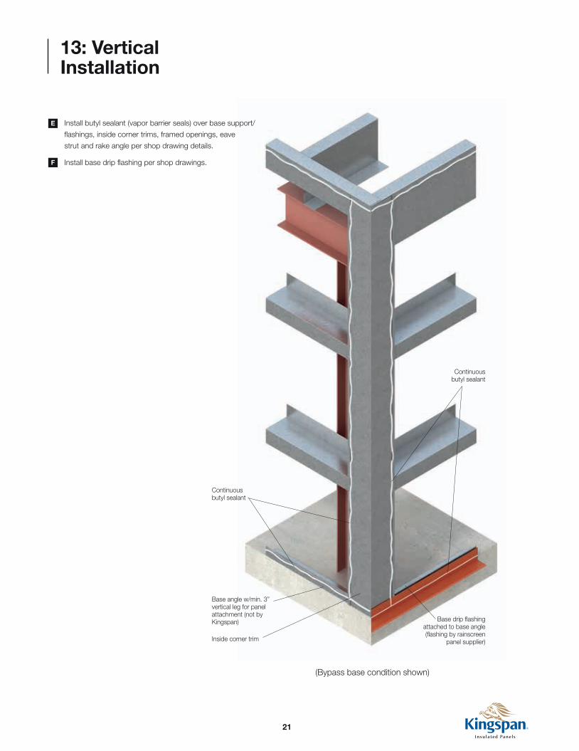
Inside corner trim
Base angle w/min. 3” vertical leg for panel attachment (not by Kingspan) Base drip flashing
attached to base angle (flashing by rainscreen
panel supplier)
Continuous butyl sealant
Continuous butyl sealant
13: Vertical Installation
Install butyl sealant (vapor barrier seals) over base support/
flashings, inside corner trims, framed openings, eave
strut and rake angle per shop drawing details.
Install base drip flashing per shop drawings.
E
F
(Bypass base condition shown)
22
13: Vertical Installation
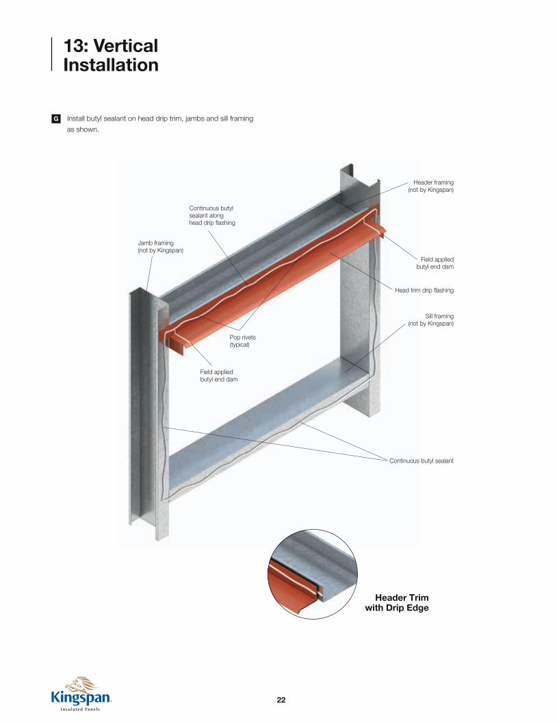
Install butyl sealant on head drip trim, jambs and sill framing
as shown.
G
Header Trim with Drip Edge
Sill framing (not by Kingspan)
Head trim drip flashing
Field applied butyl end dam
Header framing (not by Kingspan)
Jamb framing (not by Kingspan)
Continuous butyl sealant
Continuous butyl sealant along head drip flashing
Pop rivets (typical)
Field applied butyl end dam

23
Cut joint from trailing edge of starter panel
Leading edge
13: Vertical Installation
Sheeting is typically installed from left to right. (Sheeting
direction may be changed by rotating panels 180° to change
direction of joints).
Cut the joints off trailing edge of the starter panel as shown.
Be sure to cut first panel to proper width so that panel joints at
framed openings are properly aligned.
H
I
Panel joints offset from jamb
(preferred condition for better seal at jamb conditions)
Panel joints align with jamb
Framed Opening Locations
Exterior face
Interior face
NOTEThe leading edge is defined as the side of the panel with the hidden KarrierRail™ edge and fasteners.
IMPORTANT INSTALLATION NOTEPanel layouts on the shop drawings should be drawn so that the vertical joints of the panel DO NOT line up with edges of framed openings. Lining up the vertical joints at penetrations does NOT allow proper weather seals due to the offset joint configuration of the KarrierPanel™.

24
Starter panel
Trailing edge starter panel
Leading edge
13: Vertical Installation
Verify liner side joint sealant has been installed (per Section 10).
Sealant quantity should be adequate to properly seal male to
female joints (approx. 50% to 75% fill in female pocket).
Lift starter panel into place and press firmly into structure
to seat panel into butyl sealant placed on the structure and
associated trims per step E above.
J
K

25
13: Vertical Installation
Verify panel is vertical using a level placed on leading (non-cut)
edge.
Attach KarrierRail™ and panel with 2 fasteners at EVERY
structural support per shop drawings.
Attach trailing (cut edge) of panel to corner structure with
fasteners as required per shop drawings. Do not overtighten
the fasteners as panel damage will result.
L
Eave strut (not by Kingspan)
Intermediate support (not by Kingspan)
Leading edge
KarrierRail™ with fasteners per
shop drawings
Base angle w/min. 3” vertical leg for panel attachment (not by Kingspan)
Typical overhang base condition shown

26
13: Vertical Installation
Attach trailing edge of KarrierRail™ to panel face with expansion
fasteners per shop drawings. Contact Kingspan Technical
Services for size, type and spacing of expansion fasteners.
M
1/4” - 14 Hex head fasteners with washer
Wall panel installation direction
Set KarrierRail™ in butyl sealant at fastener locations
Expansion fastener as required
Continuous Karrier™ (KarrierRail™ available in 1 - 3” faces)
Male joint Female joint
Horizontal support (not by Kingspan)
Continuous butyl sealant
Continuous butyl sealant (optional)

27
13: Vertical Installation
Install marriage bead of sealant from interior joint to supporting
structure at EVERY panel termination, i.e. bottom of wall at
base support, at framed openings AND at top of wall at eave
strut.
N
Base Condition
Eave Condition
NOTEMarriage beads are critical to ensure proper vapor barriers and are required at all panel terminations.
NOTEVerify panels are completely engaged, with proper sealant contact and joint reveals.
Framed Opening Condition
See inset detail
Continuous butyl sealant
Marriage bead
Continuous butyl sealant
Eave strut (not by Kingspan)
See inset detail
Marriage bead
Framed Opening Head with Drip Edge
28
13: Vertical Installation
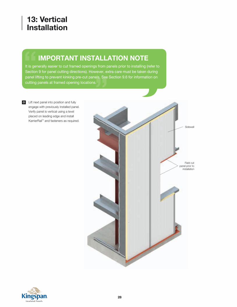
Lift next panel into position and fully
engage with previously installed panel.
Verify panel is vertical using a level
placed on leading edge and install
KarrierRail™ and fasteners as required.
O
Field cut panel prior to
installation
Sidewall
IMPORTANT INSTALLATION NOTEIt is generally easier to cut framed openings from panels prior to installing (refer to Section 9 for panel cutting directions). However, extra care must be taken during panel lifting to prevent kinking pre-cut panels. See Section 9.6 for information on cutting panels at framed opening locations.

29
13: Vertical Installation
Repeat steps K through N until wall elevation is completed.P

30
13: Vertical Installation
Repeat process for other wall elevations. For non-parapet wall
conditions, endwall (rake wall) panels must be field cut to match
slope of roof.
Once all walls are sheeted, install exterior corner trims as
required. Follow fastening information on project shop drawings.
Q
R
NOTESee page 35 for detailed instructions on framed opening trim assembly.
Framed opening trim with pop
rivets required
Sidewall
Base trim with pop rivets as required
Outside corner trim with pop rivets as required
Continuous butyl sealant
Outside corner trim
F.I.P. Insulation as required (by others)
Pop rivets
Continuous butyl sealant
Attached clip (by others)
3/4” Phil. pan head
Inside corner trim
Horizontal support
Outside Corner with Flat Trim Detail
1/4” - 14 “low profile” through fastener (as required for wind load)
Endwall (rake wall)

31
1/4” - 14 Hex head fasteners with washer
Hat channel set in butyl sealant at fastener locations
Framed opening (not by Kingspan)
1/4” - 14 “low profile” through fasteners
13: Vertical Installation
Attach hat channels at jambs of framed openings (gauge and
size to match the KarrierRail™).
S Hat Channels at Framed Openings
Hat channels
32
13: Vertical Installation
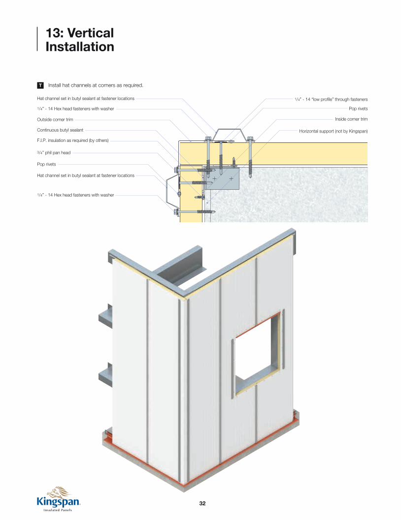
Install hat channels at corners as required.T
1/4” - 14 Hex head fasteners with washer
Outside corner trim
F.I.P. insulation as required (by others)
1/4” - 14 “low profile” through fasteners
Pop rivets
Continuous butyl sealant
Hat channel set in butyl sealant at fastener locations
1/4” - 14 Hex head fasteners with washer
Inside corner trim
Horizontal support (not by Kingspan)
Hat channel set in butyl sealant at fastener locations
Pop rivets
3/4” phil pan head

33
13: Vertical Installation
Install rainscreen panel per manufacturer’s instructions.U
Install continuous starter clip along base
of panels and secure with fasteners per
rainscreen details.
Install rainscreen panels and secure to
KarrierRail™ with clips and fasteners per
rainscreen details.
Engage panel and repeat until
wall is covered.
NOTERainscreen orientation may be rotated 90° by adding hat channels over the top of the KarrierRail™. Contact Kingspan Technical Services for more information.
34
13: Vertical Installation
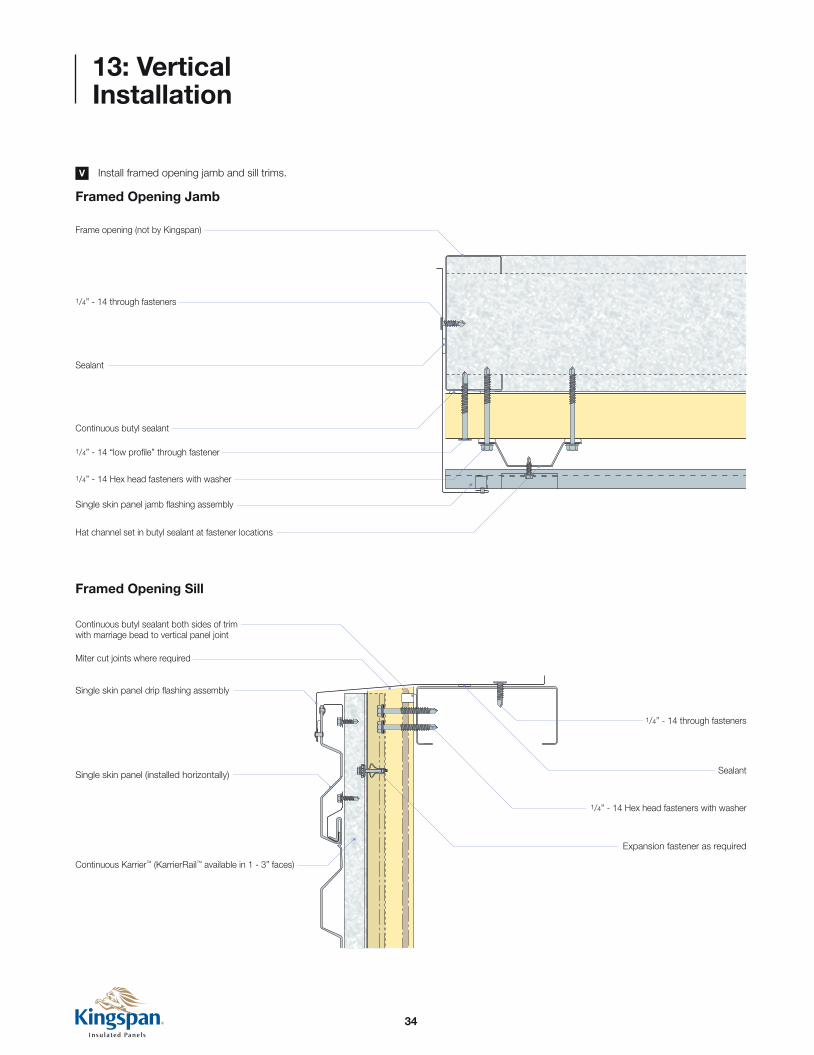
Install framed opening jamb and sill trims.V
Framed Opening Jamb
Sealant
Frame opening (not by Kingspan)
1/4” - 14 through fasteners
1/4” - 14 “low profile” through fastener
1/4” - 14 Hex head fasteners with washer
Single skin panel jamb flashing assembly
Hat channel set in butyl sealant at fastener locations
Continuous butyl sealant
Framed Opening Sill
1/4” - 14 Hex head fasteners with washer
1/4” - 14 through fasteners
Sealant
Expansion fastener as required
Continuous Karrier™ (KarrierRail™ available in 1 - 3” faces)
Single skin panel (installed horizontally)
Single skin panel drip flashing assembly
Continuous butyl sealant both sides of trim with marriage bead to vertical panel joint
Miter cut joints where required
35
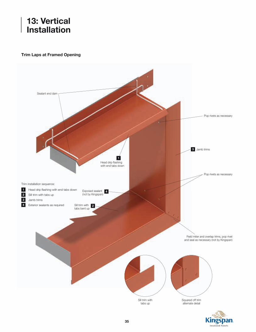
13: Vertical Installation
Trim Laps at Framed Opening
Jamb trims
Pop rivets as necessary
Pop rivets as necessary
Exposed sealant (not by Kingspan)
Sill trim with tabs bent up
Field miter and overlap trims, pop rivet and seal as necessary (not by Kingspan)
Sealant end dam
Head drip flashing with end tabs down
Squared off trim alternate detail
Sill trim with tabs up
Trim installation sequence:
Head drip flashing with end tabs down
Sill trim with tabs up
Jamb trims
Exterior sealants as required
1
2
3
4 2
3
1
4
36
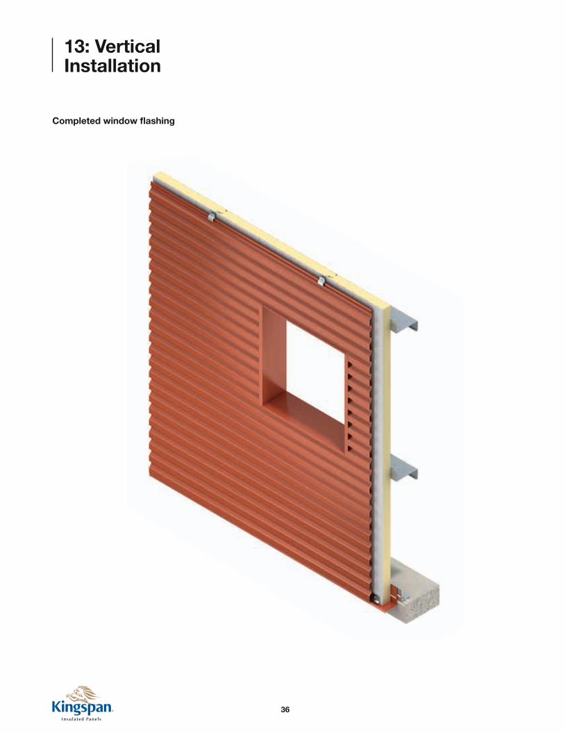
13: Vertical Installation
Completed window flashing

37
Framed Opening Head
1/4” - 14 Hex head fasteners with washer
Framed opening (not by Kingspan)
Expansion fastener as required
Continuous Karrier™ (KarrierRail™ available in 1 - 3” faces)
Single skin panel (installed horizontally)
Single skin panel continuous starter/flashing
Single skin panel drip flashing assembly
Continuous butyl sealant both sides of trim with marriage bead to vertical panel joint
Exposed sealant (not by Kingspan)
Door/window frame (not by Kingspan)
14: Vertical Construction Details
DisclaimerThese details are designed to show how single skin metal panels integrate with the KarrierPanel™ system. Please consult the rainscreen panel manufacturer you are using for installation instructions, exact trim profiles and project specific details.
NOTESee page 35 for more information on framed opening trim installation.
Framed Opening Sill
1/4” - 14 Hex head fasteners with washer
1/4” - 14 through fasteners
Sealant
Expansion fastener as required
Continuous Karrier™ (KarrierRail™ available in 1 - 3” faces)
Single skin panel (installed horizontally)
Single skin panel drip flashing assembly
Continuous butyl sealant both sides of trim with marriage bead to vertical panel joint
Exposed sealant (not by Kingspan)
Miter cut joints where required
Door/window frame (not by Kingspan)
Vertical KarrierPanel™ with Horizontal Metal Rainscreen Details
38
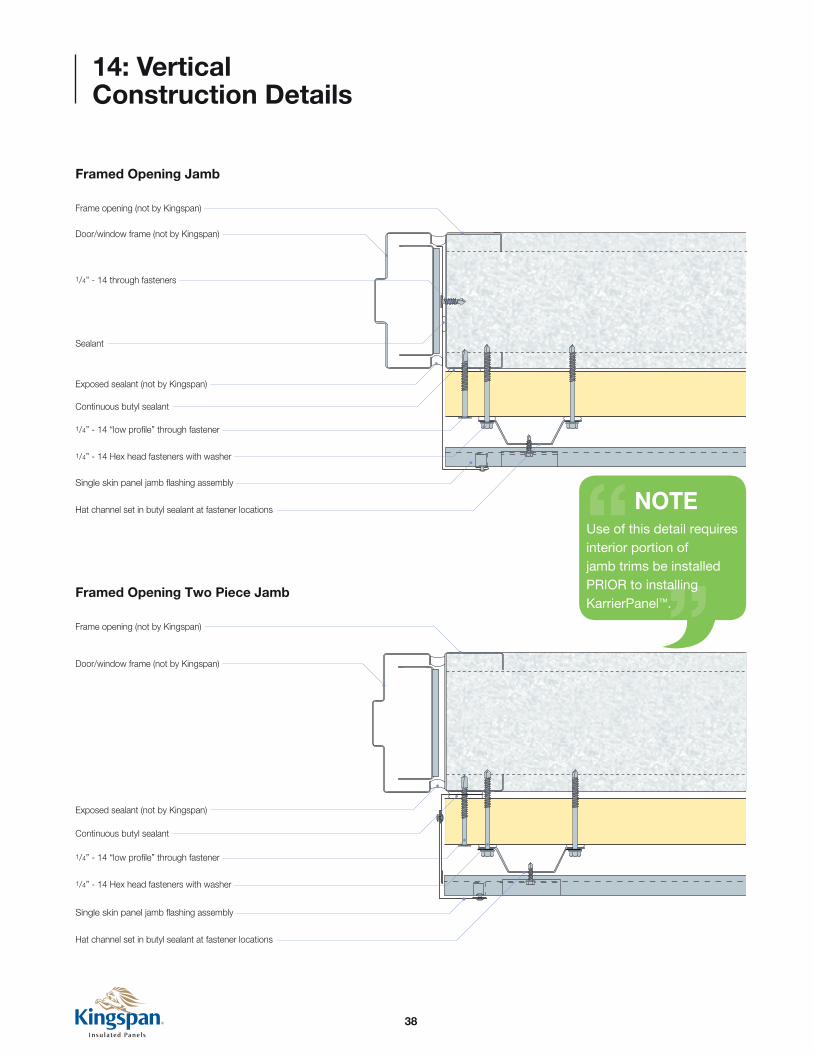
Framed Opening Jamb
Sealant
Door/window frame (not by Kingspan)
Frame opening (not by Kingspan)
1/4” - 14 through fasteners
1/4” - 14 “low profile” through fastener
1/4” - 14 Hex head fasteners with washer
Single skin panel jamb flashing assembly
Hat channel set in butyl sealant at fastener locations
Continuous butyl sealant
Exposed sealant (not by Kingspan)
Framed Opening Two Piece Jamb
Door/window frame (not by Kingspan)
Frame opening (not by Kingspan)
1/4” - 14 “low profile” through fastener
1/4” - 14 Hex head fasteners with washer
Single skin panel jamb flashing assembly
Hat channel set in butyl sealant at fastener locations
Continuous butyl sealant
Exposed sealant (not by Kingspan)
14: Vertical Construction Details
NOTEUse of this detail requires interior portion of jamb trims be installed PRIOR to installing KarrierPanel™.

39
14: Vertical Construction Details
Base - Flush
Base at Notched Concrete
1/4” - 14 Hex head fasteners with washer
Base angle with minimum 3” vertical leg for panel attachment set in sealant (not by Kingspan)Expansion fastener as required
Continuous Karrier™ (KarrierRail™ available in 1 - 3” faces)
Single skin panel (installed horizontally)
Base flashing
Continuous butyl sealant below base flashing
Continuous butyl sealant
Single skin panel continuous starter/flashing
Continuous butyl sealant both sides of trim with marriage bead to vertical panel joint
Fastener to concrete (not by Kingspan)
Set Karrier™ (KarrierRail™ in butyl sealant at fastener locations
1/4” - 14 Hex head fasteners with washer
Expansion fastener as required
Continuous Karrier™ (KarrierRail™ available in 1 - 3” faces)
Set KarrierRail™ in butyl sealant at fastener locations
Single skin panel (installed horizontally)
Single skin panel continuous starter/flashing
Base flashing
Continuous butyl sealant below base flashing
Base angle with minimum 3” vertical leg for panel attachment set in sealant (not by Kingspan)
Fastener to concrete (not by Kingspan)
Continuous butyl sealant both sides of trim with marriage bead to vertical panel joint
40
14: Vertical Construction Details
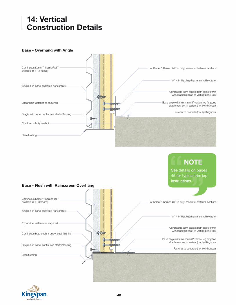
Base - Overhang with Angle
Base - Flush with Rainscreen Overhang
Single skin panel (installed horizontally)
Continuous butyl sealant below base flashing
1/4” - 14 Hex head fasteners with washer
Base angle with minimum 3” vertical leg for panel attachment set in sealant (not by Kingspan)
Expansion fastener as required
Continuous Karrier™ (KarrierRail™ available in 1 - 3” faces)
Base flashing
Base flashing
Continuous butyl sealant
Set Karrier™ (KarrierRail™ in butyl sealant at fastener locations
Single skin panel continuous starter/flashing
Continuous butyl sealant both sides of trim with marriage bead to vertical panel joint
Fastener to concrete (not by Kingspan)
Single skin panel (installed horizontally)
1/4” - 14 Hex head fasteners with washer
Base angle with minimum 3” vertical leg for panel attachment set in sealant (not by Kingspan)
Expansion fastener as required
Continuous Karrier™ (KarrierRail™
available in 1 - 3” faces) Set Karrier™ (KarrierRail™ in butyl sealant at fastener locations
Single skin panel continuous starter/flashing
Continuous butyl sealant both sides of trim with marriage bead to vertical panel joint
Fastener to concrete (not by Kingspan)
NOTESee details on pages 45 for typical trim lap instructions.

41
14: Vertical Construction Details
Will vary with field condition
Will
vary
with
fie
ld c
ondi
tion
Field cut
Outside Corner with Flat Trim
Will vary with field condition
Will
vary
with
fie
ld c
ondi
tion
Field cut
Inside Corner with Flat Trim
1/4” - 14 Hex head fasteners with washer
3/4” Phil pan head
3/4” Phil pan head
3/4” Phil pan head
Hat channel set in butyl sealant at fastener locations
Hat channel set in butyl sealant at fastener locations
Hat channel set in butyl sealant at fastener locations
Single skin panel inside corner assembly
Outside corner trim
Single skin panel (installed horizontally)
Hat channel set in butyl sealant at fastener locations
Horizontal support (not by Kingspan)
Horizontal support (not by Kingspan)
Single skin panel (installed horizontally)
Pop rivets
Pop rivets
Inside corner trim
Inside corner trim
Outside corner trim
Continuous butyl sealant
F.I.P. insulation as required (by others)
F.I.P. insulation as required (by others)
1/4” - 14 “low profile” through fasteners
Pop rivets
Pop rivets
Continuous butyl sealant
Continuous butyl sealant
1/4” - 14 “low profile” fastener with 11/8” bonded washer
1/4” - 14 “low profile” fastener with 11/8” bonded washer
Single skin panel (installed horizontally)
1/4” - 14 Hex head fasteners with washer
Single skin panel outside corner assembly
1/4” - 14 Hex head fasteners with washer
1/4” - 14 Hex head fasteners with washer

42
14: Vertical Construction Details
1/4” - 14 Hex head fasteners with washer
1/4” - 14 “low profile” fastener with 11/8” bonded washer
Continuous butyl sealant
Structural supports (not by Kingspan)
Cap trim
Backer rod and sealant (not by Kingspan)
Hat channel set in butyl sealant at fastener locations
Single skin panel (installed horizontally)
Single skin panel cap trim assembly
Panel Termination

43
14: Vertical Construction Details
NOTENumbers indicate order of panel installation.
NOTEFor wall elevations requiring stack joints, it is recommended that each column of panels is installed at the same time to maintain proper vertical reveal alignment.
2
Stack Joint
3 7
1/4” - 14 Hex head fasteners with washer
1/4” - 14 Hex head fasteners with washer
Horizontal supports (not by Kingspan)
Expansion fastener as required
Expansion fastener as required
Fastener as required (not by Kingspan)
Continuous Karrier™ (KarrierRail™ available in 1 - 3” faces)
Continuous Karrier™ (KarrierRail™ available in 1 - 3” faces)
Note: Field notch KarrierRail™ as required
Continuous Karrier™ (KarrierRail™ available in 1 - 3” faces)
Continuous butyl sealant both sides of trim with marriage bead to vertical panel joint
Continuous butyl sealant both sides of trim with marriage bead to vertical panel joint
Fastener to parapet backer (not by Kingspan)
Membrane roof and parapet backer (not by Kingspan)
Single skin panel (installed horizontally)
Single skin panel (installed horizontally)
F.I.P. insulation as required (by others)
Expansion fastener as required
Parapet blocking (not by Kingspan)
Single skin panel parapet assembly
Wrap membrane over panel face (not by Kingspan)
1/4” - 14 Hex head fasteners with washer
Parapet
1 15 39 53 27 411 6
76 104 88 12

44
14: Vertical Construction Details
Low Eave
Rake
1/4” - 14 Hex head fasteners with washer
1/4” - 14 Hex head fasteners with washer
Eave strut (not by Kingspan)
Expansion fastener as required
Expansion fastener as required
Continuous Karrier™ (KarrierRail™ available in 1 - 3” faces)
Continuous Karrier™ (KarrierRail™ available in 1 - 3” faces)
Rake angle (not by Kingspan)
Continuous butyl sealant both sides of trim with marriage bead to vertical panel joint
Continuous butyl sealant both sides of trim with marriage bead to vertical panel joint
F.I.P. insulation as required (by others)
F.I.P. insulation as required (by others)
Refer to 900/1000 Series roof panel details for additional information
Refer to 900/1000 Series roof panel details for additional information

45
14: Vertical Construction Details
Trim Lap
Min. 3˚
trim lap
Min. 3˚
trim lap
(2) beads butyl sealant
Trim Lap with Notched Hem
Trim Lap with Lap Strip
8” long lap strip
(2) beads butyl sealant
Min. 3˚
trim lap
Min. 3˚
trim lap
(2) beads butyl sealant
Field notch hem(s) as required (not by Kingspan)
Nom. 1/4”
gap

46
15: Horizontal Installation
NOTECare must be taken to properly seal all framed openings. Sealant MUST be installed between trims and supporting steel AND between trims and back side of panels.
Verify that all structural supports are properly aligned before
installing panels (refer to Section 8 Structural Alignment -
Horizontal Panels).
Install continuous mending plates at all vertical reveal locations.
Using a level, mark the centerline of all vertical reveal joints on
mending plates to match locations shown on shop drawings.
Verify all framed opening locations. Apply butyl sealant to
outside face of steel supports/studs around framed openings.
Install head drip flashing and tack in place as necessary.
Apply butyl sealant to head drip flashing as shown on opposite page.
This serves to form both a weather and vapor seal to the back side
of the panels.
A
B
C
IMPORTANT INSTALLATION NOTES n Minimum width of load-bearing steel exposed behind two horizontal panels at vertical joint is 5” nominal (approx. 127mm) which could be provided by standard double steel stud configuration with steel backer plate. Optional I-beam or HSS steel sections. n Minimum bearing face for intermediate support is 1.625” (approx. 42mm). n Where long runs of integrated strip windows are installed, the vertical panel joints should terminate above and continue below the window units. n Visually check all internal and external tongue-and-groove joints between two adjacent panels to ensure panels are engaged fully and the gaps do not exceed tolerances. n Details shown in this guide are for reference only. Consult project shop drawings for actual details required.

47
15: Horizontal Installation
Continuous butyl sealant
Drip flashing
Door/window frame (not by Kingspan)
Exposed sealant (not by Kingspan)
One Piece Head Detail with Drip Edge
(Typical framed opening head conditions)
Framed opening (not by Kingspan)
Pop rivets
Sill framing (not by Kingspan)
Field applied butyl end dams (typical)
Header framing (not by Kingspan)
Jamb framing (not by Kingspan)
Interior header trim

48
1/4” - 14 Hex head fasteners with 11/8” bonded washer
1/4” - 14 Hex head fasteners with 11/8” bonded washerBase flashing
Base flashing
Fastener to concrete (not by Kingspan) Fastener to concrete
(not by Kingspan)
Vertical supports (not by Kingspan) Vertical supports
(not by Kingspan)Continuous butyl sealant both sides of trim
Continuous butyl sealant both sides of trim
Base channel set in sealant (not by Kingspan)
Continuous butyl sealant below base flashing
Base channel set in sealant (not by Kingspan)
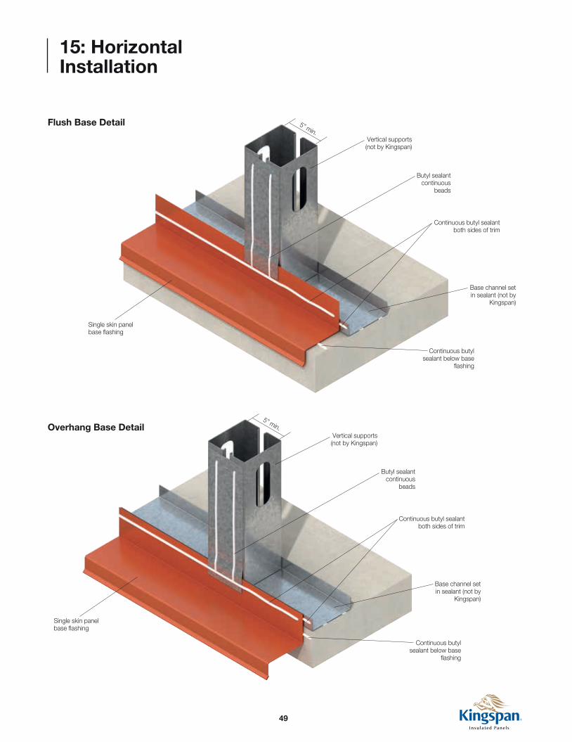
15: Horizontal Installation
Panel Attachment at the Base
Install base trim per project shop drawings. Trim must be level
and set in butyl sealant.
Apply beads of butyl sealant on vertical mending plates as
shown.
D
E
49
15: Horizontal Installation
Butyl sealant continuous
beads
Vertical supports (not by Kingspan)
Base channel set in sealant (not by
Kingspan)
5” min.
Continuous butyl sealant both sides of trim
Continuous butyl sealant below base
flashing
Flush Base Detail
5” min.
Single skin panel base flashing
Butyl sealant continuous
beads
Vertical supports (not by Kingspan)
Base channel set in sealant (not by
Kingspan)
Continuous butyl sealant both sides of trim
Continuous butyl sealant below base
flashing
Single skin panel base flashing
Overhang Base Detail

50
F.I.P. insulation as required (by others)
Field miter cut panels
Pop rivets
Continuous butyl sealant at panel joint
1/4” -14 Hex head fasteners with
washer
Continuous KarrierRail™
Expansion Fastener at KarrierRail™ (below)
Inside corner trim
Set KarrierRail™
in butyl sealant at fastener locations
Continuous butyl sealant with marriage
bead to horizontal panel joint
P2
P1
NOTECut panels in field as necessary for framed openings (see section 9).
Mitre Cut Corner Detail
Butyl sealant behind panel
Vertical mending plate
1/4” - 14 hex head fasteners with washer
KS Horizontal panel(P1)
Marriage bead
Line of vertical reveal
Centerline of mending plate
Stainless steel hidden fastener
clips
(See Vertical Joint Assembly - Panel P1)
Vertical support (not by Kingspan)
Outside corner trim
15: Horizontal Installation
Panel Installation - Bottom Row
Starting from the corner, measure to the centerline of the first
vertical mending plate.
Cut panel P1 to length. Mitre cut corner as shown in detail.
Set panel P1 as shown. Notch top flanges of rail at corner as
necessary to accommodate mitre cut panel.
Fasten panel and rail into supporting steel with clips and
fasteners as indicated on shop drawings.
Once panel is secured, apply butyl sealant over the interior male
lip at both panel ends to create marriage beads to the inside
corner trim (left edge of panel) and vertical mending plate (right
edge of panel).
Cut panel P2 to length as required, and install panel and rail
with fasteners per shop drawings. Gaps between the ends
of panels P1 and P2 larger than 1/4” should be filled with
expandable foam insulation.
F
J
H
G
K
I

51
15: Horizontal Installation
NOTEVerify panels are completely engaged, with proper sealant contact and joint reveals.
CAUTIONDo not over-tighten fasteners as damage to the panel core as well as facings will result.
Intermediate Fastener PositionVertical Joint Assembly at Corner- Panel P1
Panel fastener with KarrierRail™
Marriage beads of butyl sealant (at vertical joint)
Steel stud at vertical joint
Mending plate
P1
P2
Vertical Joint Assembly
Panel fastener with KarrierRail™
Marriage bead of butyl sealant (at vertical joint)
Mending plate
Continuous vertical butyl sealant
P1
Steel stud at vertical joint
Panel fastener with KarrierRail™
Steel stud framing
P1
52
P1
P3
P4P2
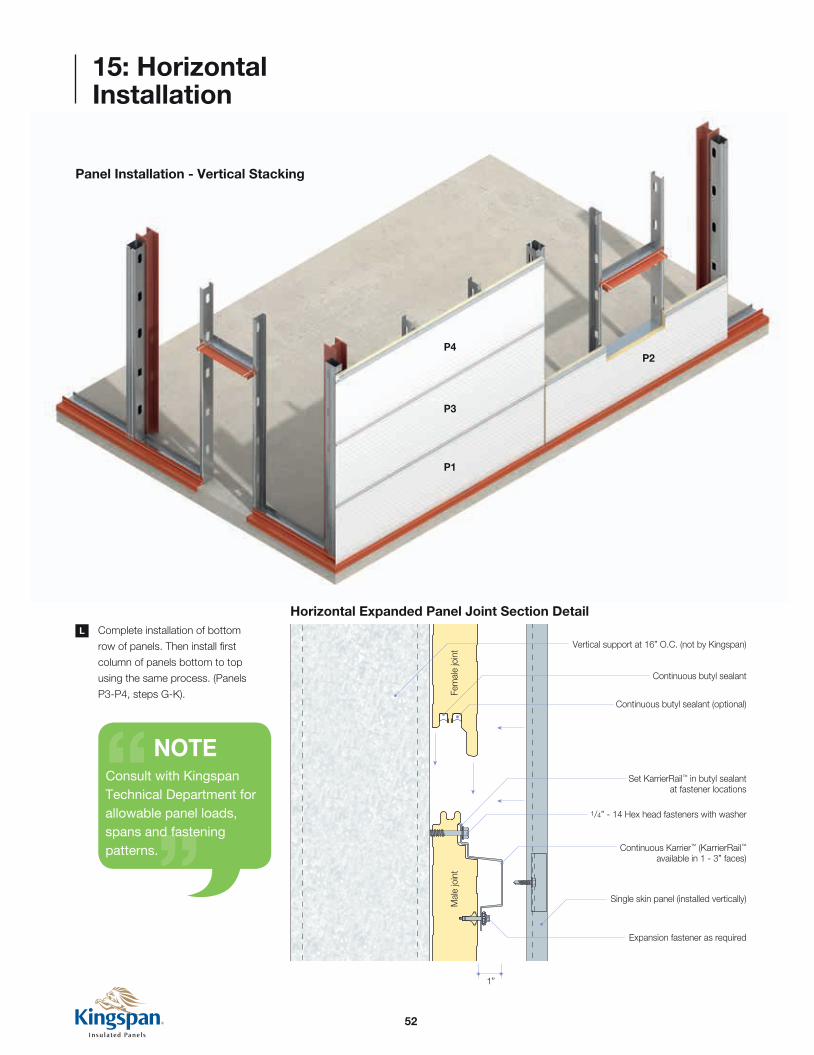
Horizontal Expanded Panel Joint Section Detail
1/4” - 14 Hex head fasteners with washer
Set KarrierRail™ in butyl sealant at fastener locations
Expansion fastener as required
Continuous Karrier™ (KarrierRail™
available in 1 - 3” faces)
Single skin panel (installed vertically)Mal
e jo
int
1”
Fem
ale
join
t Vertical support at 16” O.C. (not by Kingspan)
Continuous butyl sealant
Continuous butyl sealant (optional)
15: Horizontal Installation
Panel Installation - Vertical Stacking
Complete installation of bottom
row of panels. Then install first
column of panels bottom to top
using the same process. (Panels
P3-P4, steps G-K).
L
NOTEConsult with Kingspan Technical Department for allowable panel loads, spans and fastening patterns.

53
15: Horizontal Installation
Once the first building elevation is completed (P1-P7), start
around the corner on next elevation using the same sequence
and method (P8-12).
M
NOTENumbers indicate order of panel installation.
NOTETo minimize panel cutting, panel lengths should be pre-determined to align with framed opening jambs.
Assembly Sequence
P8
P9
P7
P1
P3
P4P2
P6
P5
P10
P11
P12

54
15: Horizontal Installation
Install P8 into corner as shown. (Mitre cut panel and notch
KarrierRail™ as required).
Install butyl sealant marriage beads from interior corner trim to
interior male joint (right edge of panel) and door jamb (left edge
of panel).
Install P9 with marriage beads to mending plate (left edge of
panel) and door jamb (right edge of panel).
Install remaining panels, repeating steps N-P as necessary.
N
O
P
Q
Outside Corner - Detail
F.I.P. insulation as required (by others)
Outside corner trim
Field miter cut panels
Pop rivets
Continuous butyl sealant at panel joint
Notch the KarrierRail™ as necessary to allow for the installation of the corner trim and/or membrane material
1/4” -14 Hex head fasteners with washer
Continuous KarrierRail™
Expansion Fastener at KarrierRail™ (below)
Set KarrierRail™ in butyl sealant at fastener locations
Continuous butyl sealant with marriage bead to horizontal panel joint
Inside corner trim
Vertical support (not by Kingspan)

55
P8
P9
P7
P1
P3
P4P2
P6
P5
P10
P11
P12
Corner Condition
15: Horizontal Installation
56
15: Horizontal Installation
P8
P9
P7
P1
P3
P4P2
P6
P5
P10
P11
P12
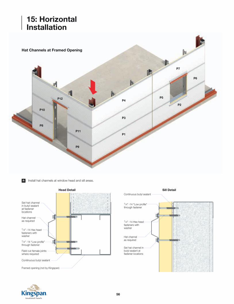
Hat Channels at Framed Opening
Install hat channels at window head and sill areas.
Head Detail
R
1/4” -14 Hex head fasteners with washer
1/4” -14 “Low profile” through fastener
Framed opening (not by Kingspan)
Hat channel as required
Set hat channel in butyl sealant at fastener locations
Field cut female joints where required
Continuous butyl sealant
1/4” -14 Hex head fasteners with washer
Hat channel as required
Set hat channel in butyl sealant at fastener locations
Continuous butyl sealant
1/4” -14 “Low profile” through fastener
Sill Detail

57
15: Horizontal Installation
Install rainscreen panel per manufacturer’s instructions.S
NOTERainscreen orientation may be rotated 90° by adding hat channels over the top of the KarrierRail™. Contact Kingspan Technical Services for more information.
Install continuous flashing along base of
panels and secure with fasteners
per rainscreen details.
Install rainscreen panels and secure to
KarrierRail™ with clips and fasteners per
rainscreen details.
Engage panel and repeat until
wall is covered.

58
15: Horizontal Installation
T Install framed opening jamb and sill trims.
Continuous butyl sealant with marriage bead to horizontal panel joint
Set hat channel in butyl sealant at fastener locations
Set hat channel in butyl sealant at fastener locations
1/4” -14 through fastener
1/4” -14 through fastener
Sealant
Sealant
1/4” -14 Hex head fasteners with washer
1/4” -14 Hex head fasteners with washer
1/4” -14 Hex head fasteners with washer
1/4” -14 “Low Profile” through fastener
Set KarrierRail™ in butyl sealant at fastener locations
Expansion fastener at KarrierRail™ (below)
Single skin panel (installed vertically)
Single skin panel (installed vertically)
Hat channel as required
Single skin panel jamb flashing assembly
Single skin panel sill trim assembly
Field cut panel where required
Field cut male joints where required
Continuous KarrierRail™
Continuous butyl sealant

59
Jamb trims
Pop rivets as necessary
Pop rivets as necessary
Exposed sealant (not by Kingspan)
Sill trim with tabs bent up
Field miter and overlap trims, pop rivet and seal as necessary (not by Kingspan)
Sealant end dam
Head drip flashing with end tabs down
Squared off trim alternate detail
Sill trim with tabs up
Trim installation sequence:
Head drip flashing with end tabs down
Sill trim with tabs up
Jamb trims
Exterior sealants as required
1
2
3
4 2
3
1
4
15: Horizontal Installation
Trim Laps at Framed Opening

60
15: Horizontal Installation
Completed window flashing

61
DisclaimerThese details are designed to show how single skin metal panels integrate with the KarrierPanel™ system. Please consult the rainscreen panel manufacturer you are using for installation instructions, exact trim profiles and project specific details.
16: Horizontal Construction Details
1/4” -14 Hex head fasteners with washer
1/4” -14 “Low profile” through fastener
Continuous butyl sealant
Framed opening (not by Kingspan)
Door/window frame (not by Kingspan)
Hat channel as required
Single skin panel (installed vertically)
Set hat channel in butyl sealant at fastener locations
Set hat channel in butyl sealant at fastener locations
Single skin panel drip flashing assembly
Field cut female joints where required
Continuous butyl sealant
Exposed sealant (not Kingspan)
Framed Opening Head - Detail
Horizontal KarrierPanel™ with Vertical Metal Rainscreen Details
Framed Opening Sill - Detail
1/4” -14 Hex head fasteners with washer
1/4” -14 Hex head fasteners with washer
Exposed sealant (not by Kingspan)
Field cut male joints where required
Single skin panel sill trim assembly
Set hat channel in butyl sealant at fastener locations
Single skin panel (installed vertically)
Hat channel as required
Set hat channel in butyl sealant at fastener locations
Sealant
Door/window frame (not by Kingspan)
1/4” -14 Through fastener
1/4” -14 “Low profile” through fastener
Continuous butyl sealant
62
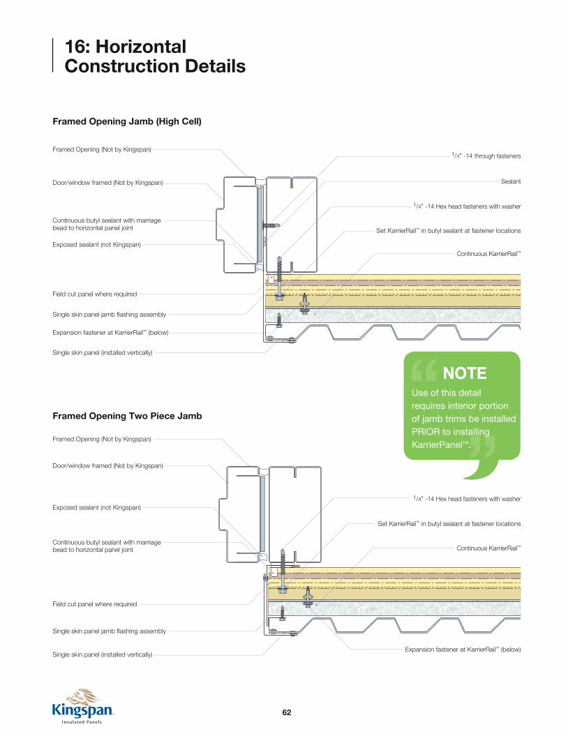
Framed Opening (Not by Kingspan)
Framed Opening (Not by Kingspan)
Door/window framed (Not by Kingspan)
Door/window framed (Not by Kingspan)
Continuous butyl sealant with marriage bead to horizontal panel joint
Continuous butyl sealant with marriage bead to horizontal panel joint
1/4” -14 through fasteners
Sealant
1/4” -14 Hex head fasteners with washer
1/4” -14 Hex head fasteners with washer
Set KarrierRail™ in butyl sealant at fastener locations
Set KarrierRail™ in butyl sealant at fastener locations
Expansion fastener at KarrierRail™ (below)
Expansion fastener at KarrierRail™ (below)
Single skin panel (installed vertically)
Single skin panel (installed vertically)
Single skin panel jamb flashing assembly
Single skin panel jamb flashing assembly
16: Horizontal Construction Details
NOTEUse of this detail requires interior portion of jamb trims be installed PRIOR to installing KarrierPanel™.
Framed Opening Jamb (High Cell)
Framed Opening Two Piece Jamb
Field cut panel where required
Field cut panel where required
Exposed sealant (not Kingspan)
Exposed sealant (not Kingspan)
Continuous KarrierRail™
Continuous KarrierRail™
63
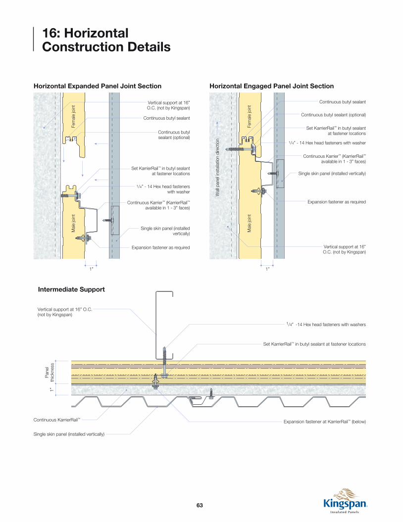
16: Horizontal Construction Details
Horizontal Expanded Panel Joint Section Horizontal Engaged Panel Joint Section
1/4” - 14 Hex head fasteners with washer
Set KarrierRail™ in butyl sealant at fastener locations
Expansion fastener as required
Continuous Karrier™ (KarrierRail™ available in 1 - 3” faces)
Single skin panel (installed vertically)
Mal
e jo
int
1” 1”
Fem
ale
join
t Vertical support at 16” O.C. (not by Kingspan)
Continuous butyl sealant
Continuous butyl sealant (optional)
1/4” - 14 Hex head fasteners with washer
Set KarrierRail™ in butyl sealant at fastener locations
Expansion fastener as required
Continuous Karrier™ (KarrierRail™ available in 1 - 3” faces)
Single skin panel (installed vertically)
Mal
e jo
int
Wal
l pan
el in
stal
latio
n di
rect
ion
Fem
ale
join
tVertical support at 16” O.C. (not by Kingspan)
Continuous butyl sealant
Continuous butyl sealant (optional)
Intermediate Support
Vertical support at 16” O.C. (not by Kingspan)
1/4” -14 Hex head fasteners with washers
Continuous KarrierRail™
Single skin panel (installed vertically)
Set KarrierRail™ in butyl sealant at fastener locations
Expansion fastener at KarrierRail™ (below)
1”P
anel
th
ickn
ess

64
16: Horizontal Construction Details
Vertical Joint
Vertical Joint between Studs
Vertical support
Vertical support
Continuous mending plate
Continuous butyl sealant with marriage bead to horizontal panel joint
Continuous mending plate
Continuous butyl sealant with marriage bead to horizontal panel joint
1”P
anel
th
ickn
ess
1”P
anel
th
ickn
ess
1/4” -14 Hex head fasteners with washer
Set KarrierRail™ in butyl sealant at fastener locations
Continuous KarrierRail™ Expansion fastener at KarrierRail™ (below)
Single skin panel (installed vertically)
Expansion fastener at KarrierRail™ (below)
Single skin panel (installed vertically)
Fill gaps 1/4” or larger with F.I.P. insulation (not by Kingspan)
5” min.
Vertical support at 16” O.C.
1/4” -14 Hex head fasteners with
washer
Set KarrierRail™ in butyl sealant at fastener locations
Continuous KarrierRail™ Fill gaps 1/4” or larger with F.I.P. insulation (not by Kingspan)
Triple stud
5” min.Optional framing

65
16: Horizontal Construction Details
Base - Flush
Continuous butyl sealant below base flashing
Single skin panel base flashing
Set hat channel in butyl sealant at fastener locations
Hat channel as required
Single skin panel (installed vertically)
1/4” -14 Hex head fasteners with 11/8” bonded washer
1/4” -14 Hex head fasteners with washer
Vertical supports (not by Kingspan)
Fastener to concrete (not by Kingspan)
Base channel set in sealant (not by Kingspan)
Continuous butyl sealant both sides of trim
Base - Flush with Extrusion
Continuous butyl sealant below base extrusion
Set hat channel in butyl sealant at fastener locations
Set hat channel in butyl sealant at fastener locations
Hat channel as required
Single skin panel (installed vertically)
1/4” -14 Hex head fasteners with washer
Vertical supports (not by Kingspan)
1/4” -14 Hex head fasteners with washer
1/4” -14 Hex head fasteners with washer
Fastener to concrete (not by Kingspan)
Continuous butyl sealant
Base channel set in sealant (not by Kingspan)
Base channel set in sealant (not by Kingspan)
Aluminum base extrusion
Fill void with compressible foam closure

66
16: Horizontal Construction Details
Base - Overhang
Base at Notched Concrete
Continuous butyl sealant below base flashing
Continuous butyl sealant
Single skin panel base flashing
Set hat channel in butyl sealant at fastener locations1/4” -14 Hex head fasteners with washer
Hat channel as required
Single skin panel (installed vertically)
Single skin panel base flashing
1/4” -14 Hex head fasteners with 11/8” bonded washer
Vertical supports (not by Kingspan)
Fastener to concrete (not by Kingspan)
Base channel set in sealant (not by Kingspan)
Continuous butyl sealant both sides of trim
Continuous butyl sealant
1/4” -14 Hex head fasteners with washer
Set hat channel in butyl sealant at fastener locations
Set hat channel in butyl sealant at fastener locations
Hat channel as required
Single skin panel (installed vertically)
1/4” -14 Hex head fasteners with 11/8” bonded washer
Vertical supports (not by Kingspan)
Fastener to concrete (not by Kingspan)
Base channel set in sealant (not by Kingspan)
Continuous butyl sealant both sides of trim

67
16: Horizontal Construction Details
Base - Flush with Rainscreen Overhang
Set hat channel in butyl sealant at fastener locations
Hat channel as required
Single skin panel (installed vertically)
1/4” -14 Hex head fasteners with 11/8” bonded washer
1/4” -14 Hex head fasteners with washer
Vertical supports (not by Kingspan)
Fastener to concrete (not by Kingspan)
Base channel set in sealant (not by Kingspan)
Continuous butyl sealant both sides of trimSet hat channel in butyl sealant at fastener locations
Base flashing
Continuous butyl sealant below base flashing

68
16: Horizontal Construction Details
Outside Corner (High Cell) - Detail
Outside Corner (Low Cell) - Detail
Vertical support (not by Kingspan)
Inside corner trim
Continuous butyl sealant with marriage bead to horizontal panel joint
Continuous butyl sealant at panel joint
Single skin panel (installed vertically)
Pop rivets
Field miter cut panels
F.I.P. Insulation as required (by others)
Outside corner trim
Single skin panel outside corner assembly
Single skin panel (installed vertically)
1/4” -14 Hex head fasteners with washer
Continuous KarrierRail™
Expansion fastener at KarrierRail™ (blow)
Set KarrierRail™ in butyl sealant at fastener locations
Continuous butyl sealant at panel joint
Single skin panel (installed vertically)
Pop rivets
Field miter cut panels
F.I.P. Insulation as required (by others)
Outside corner trim
Single skin panel outside corner assembly
Single skin panel (installed vertically)
Vertical support (not by Kingspan)
Inside corner trim
Continuous butyl sealant with marriage bead to horizontal panel joint
1/4” -14 Hex head fasteners with washer
Continuous KarrierRail™
Expansion fastener at KarrierRail™ (blow)
Set KarrierRail™ in butyl sealant at fastener locations
69
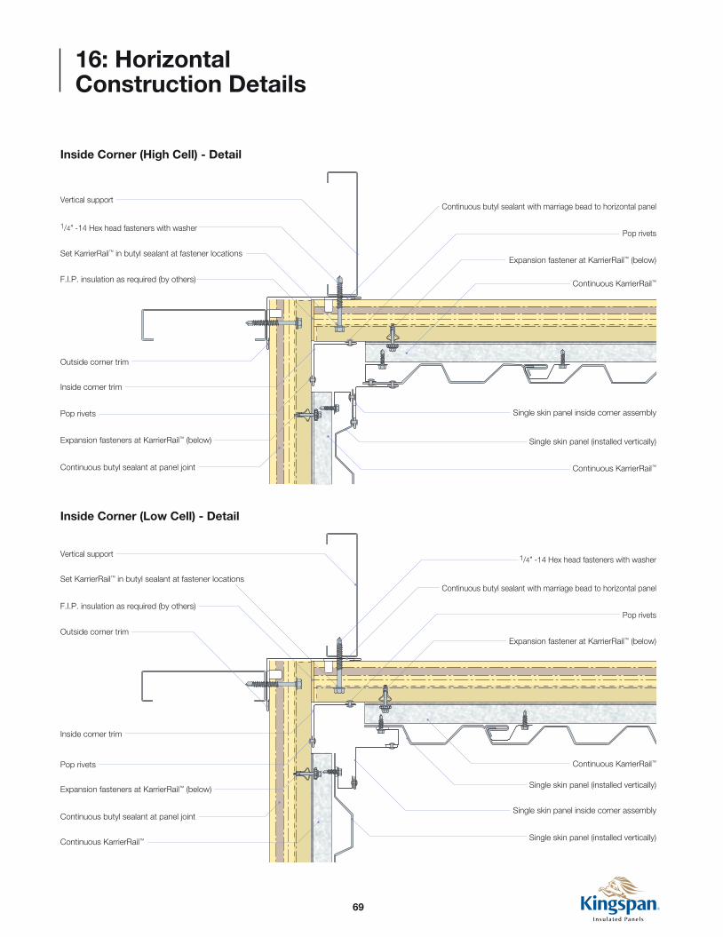
16: Horizontal Construction Details
Inside Corner (High Cell) - Detail
Inside Corner (Low Cell) - Detail
Continuous KarrierRail™
Continuous KarrierRail™
Single skin panel (installed vertically)
Single skin panel (installed vertically)
Single skin panel inside corner assembly
Expansion fasteners at KarrierRail™ (below)
Continuous butyl sealant at panel joint
Set KarrierRail™ in butyl sealant at fastener locations
F.I.P. insulation as required (by others)
Outside corner trim
Inside corner trim
Pop rivets
1/4” -14 Hex head fasteners with washerVertical support
Expansion fastener at KarrierRail™ (below)
Continuous butyl sealant with marriage bead to horizontal panel
Pop rivets
Continuous KarrierRail™
Continuous KarrierRail™
Single skin panel (installed vertically)
Single skin panel inside corner assembly
Expansion fasteners at KarrierRail™ (below)
Continuous butyl sealant at panel joint
Set KarrierRail™ in butyl sealant at fastener locations
F.I.P. insulation as required (by others)
Outside corner trim
Inside corner trim
Pop rivets
1/4” -14 Hex head fasteners with washer
Vertical support
Expansion fastener at KarrierRail™ (below)
Continuous butyl sealant with marriage bead to horizontal panel
Pop rivets
70
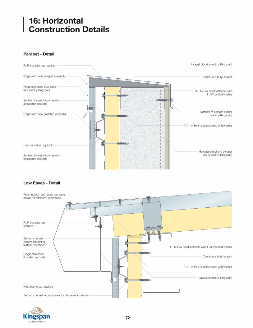
16: Horizontal Construction Details
Parapet - Detail
Low Eaves - Detail
1/4” -14 Hex head fasteners with 11/8” bonded washer
Fastener to parapet backer (not by Kingspan)
Membrane roof and parapet backer (not by Kingspan)Set hat channel in butyl sealant
at fastener locations
Hat channel as required
Single skin panel (installed vertically)
Set hat channel in butyl sealant at fastener locations
Wrap membrane over panel face (not by Kingspan)
Single skin panel parapet assembly
F.I.P. Insulation as required
1/4” -14 Hex head fasteners with washer
1/4” -14 Hex head fasteners with 11/8” bonded washer
Refer to 900/1000 series roof panel details for additional information
1/4” -14 Hex head fasteners with washer
Continuous butyl sealant
Continuous butyl sealant
Parapet blocking (not by Kingspan)
Eave strut (not by Kingspan)
Set hat channel in butyl sealant at fastener locations
Set hat channel in butyl sealant at fastener locations
Single skin panel (installed vertically)
Hat channel as required
F.I.P. Insulation as required

71
16: Horizontal Construction Details
Rake - Detail
1/4” -14 Hex head fasteners with 11/8” bonded washer
Refer to 900/1000 series roof panel details for additional information
1/4” -14 Hex head fasteners with washer
Continuous butyl sealant
Rake angle (not by Kingspan)
Set hat channel in butyl sealant at fastener locations
Set hat channel in butyl sealant at fastener locations
Single skin panel (installed vertically)
Hat channel as required
F.I.P. Insulation as required

72
16: Horizontal Construction Details
Panel Termination (High Cell) - Detail
Structural supports (not by Kingspan)
Cap trim
Backer rod and sealant (not by Kingspan)
Continuous KarrierRail™
Expansion fastener as required
Single skin panel (installed vertically)
Single skin panel cap trim assembly
1/4” -14 Hex head fasteners with washer
Continuous butyl sealant both sides of trim with marriage bead to horizontal panel joint
Set KarrierRail™ in butyl sealant at fastener locations
73
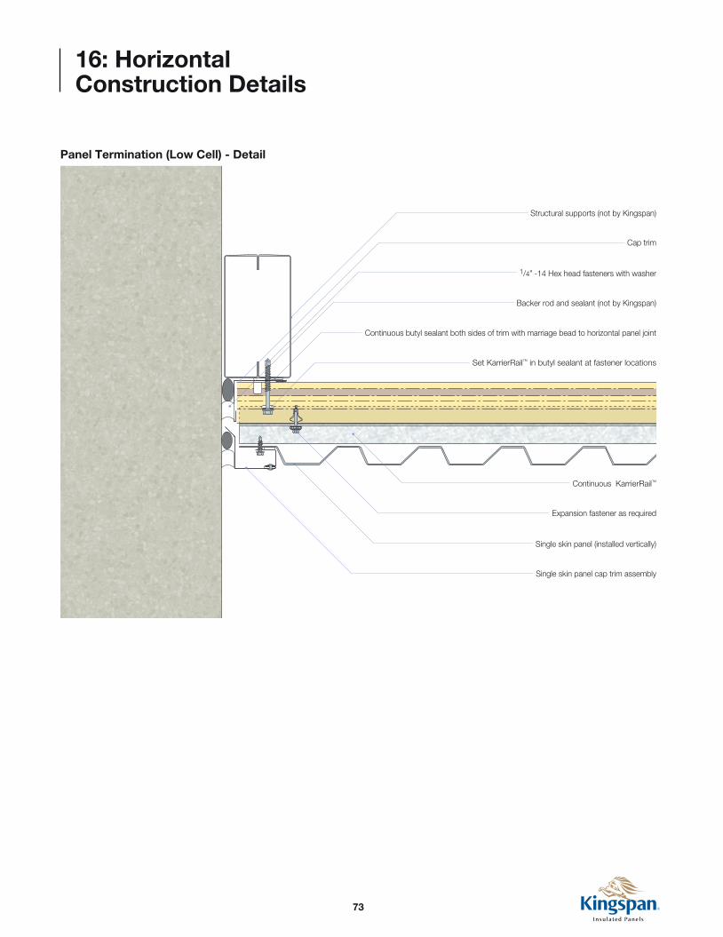
16: Horizontal Construction Details
Panel Termination (Low Cell) - Detail
Structural supports (not by Kingspan)
Cap trim
Backer rod and sealant (not by Kingspan)
Continuous KarrierRail™
Expansion fastener as required
Single skin panel (installed vertically)
Single skin panel cap trim assembly
1/4” -14 Hex head fasteners with washer
Continuous butyl sealant both sides of trim with marriage bead to horizontal panel joint
Set KarrierRail™ in butyl sealant at fastener locations
74
16: Horizontal Construction Details
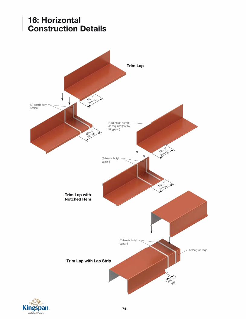
Trim Lap
Min. 3˚
trim lap
Min. 3˚
trim lap
(2) beads butyl sealant
Trim Lap with Notched Hem
Trim Lap with Lap Strip
8” long lap strip
(2) beads butyl sealant
Min. 3˚
trim lap
Min. 3˚
trim lap
(2) beads butyl sealant
Field notch hem(s) as required (not by Kingspan)
Nom. 1/4”
gap

75
16: Horizontal Construction Details
Mending Plate “Shingle” Lap Detail
(2) beads of butyl sealant
Min
. 3”
trim
lap
(2) beads of butyl sealant

76
16: Horizontal Construction Details
Base Extrusion - Optional
Base extrusion
NOTELap strips for horizontal extrusions should be set in two rows of butyl sealant at each end. Extrusions should be field drilled with weep holes within 2” of the ends of the lap strips to allow adequate drainage.

77
Notes
78
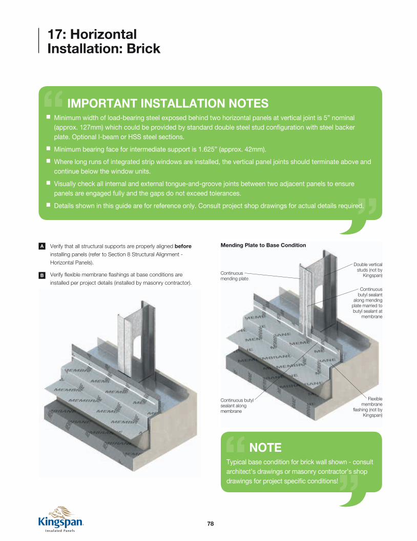
Double vertical studs (not by
Kingspan)Continuous mending plate
Continuous butyl sealant
along mending plate married to butyl sealant at
membrane
Flexible membrane
flashing (not by Kingspan)
Continuous butyl sealant along membrane
Mending Plate to Base Condition
NOTETypical base condition for brick wall shown - consult architect’s drawings or masonry contractor’s shop drawings for project specific conditions!
Verify that all structural supports are properly aligned before
installing panels (refer to Section 8 Structural Alignment -
Horizontal Panels).
Verify flexible membrane flashings at base conditions are
installed per project details (installed by masonry contractor).
A
B
17: Horizontal Installation: Brick
IMPORTANT INSTALLATION NOTES n Minimum width of load-bearing steel exposed behind two horizontal panels at vertical joint is 5” nominal (approx. 127mm) which could be provided by standard double steel stud configuration with steel backer plate. Optional I-beam or HSS steel sections. n Minimum bearing face for intermediate support is 1.625” (approx. 42mm). n Where long runs of integrated strip windows are installed, the vertical panel joints should terminate above and continue below the window units. n Visually check all internal and external tongue-and-groove joints between two adjacent panels to ensure panels are engaged fully and the gaps do not exceed tolerances. n Details shown in this guide are for reference only. Consult project shop drawings for actual details required.
79
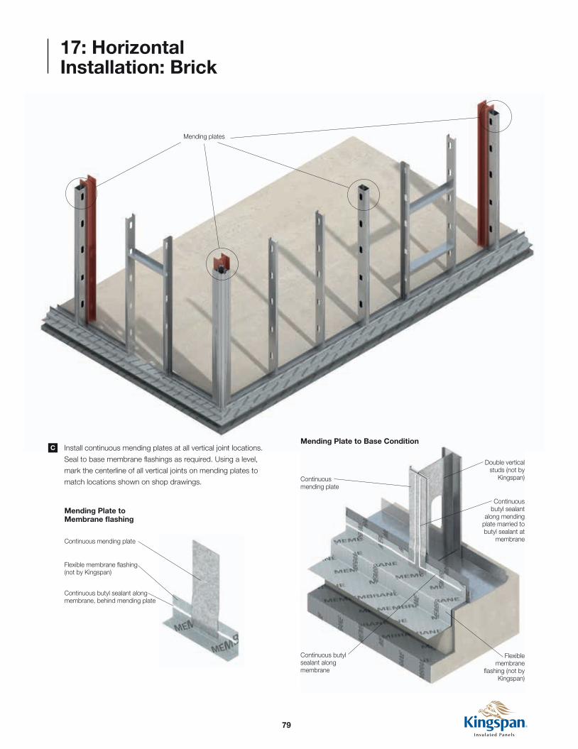
Install continuous mending plates at all vertical joint locations.
Seal to base membrane flashings as required. Using a level,
mark the centerline of all vertical joints on mending plates to
match locations shown on shop drawings.
C
17: Horizontal Installation: Brick
Mending plates
Double vertical studs (not by
Kingspan)Continuous mending plate
Continuous butyl sealant
along mending plate married to butyl sealant at
membrane
Flexible membrane
flashing (not by Kingspan)
Continuous butyl sealant along membrane
Mending Plate to Base Condition
Mending Plate to Membrane flashing
Continuous mending plate
Continuous butyl sealant along membrane, behind mending plate
Flexible membrane flashing (not by Kingspan)

80
17: Horizontal Installation: Brick
Verify that masonry contractor has installed membrane wraps at
all window locations similar to below.
D
Jamb to Sill Membrane Wraps - Typical
F.O. Jamb
F.O. Sill
Formed Corner Patch Self Adhering Membrane
Formed Corner Patch - Installed
Sill and Jamb Continuous Membranes
Formed corner patch
Sill vapor membrane
Corner patch
DisclaimerALL membrane and brick details shown here are informational only, and are provided to show typical interfaces and sequence of installation between the panel system and other materials.
Consult the architect’s drawings or masonry contractor’s approved shop drawings for project specific details.

81
17: Horizontal Installation: Brick
F.O. Jamb
F.O. Head
Formed Corner Patch Self Adhering Membrane
Membrane Corner Patch Self Adhering Membrane
Head and jamb continuous membranes
Corner patch
Formed corner patch
Jamb membrane
Jamb to Head Membrane Wraps - Typical
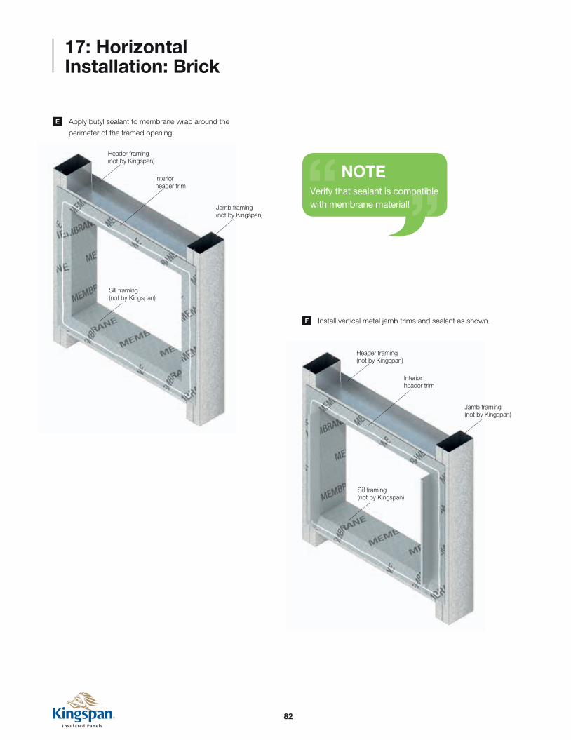
82
17: Horizontal Installation: Brick
Apply butyl sealant to membrane wrap around the
perimeter of the framed opening.
Install vertical metal jamb trims and sealant as shown.
E
F
NOTEVerify that sealant is compatible with membrane material!
Sill framing (not by Kingspan)
Header framing (not by Kingspan)
Jamb framing (not by Kingspan)
Interior header trim
Sill framing (not by Kingspan)
Header framing (not by Kingspan)
Jamb framing (not by Kingspan)
Interior header trim

83
17: Horizontal Installation: Brick
Install interior portion of outside corner trims at all corners.
Starting from the lower left corner, field cut bottom edge of
panel to remove panel joints.
G
H
First Panel Attachment at the Base
Typical Brick Wall Base Condition
Metal corner trim
Set panel in continuous butyl sealant
Panel thickness
Stud wall
Flexible membrane flashing (not by Kingspan)
Waterproofing membrane below grade (not by Kingspan)
Vertical metal stud wall column (not by Kingspan)
Continuous butyl sealant
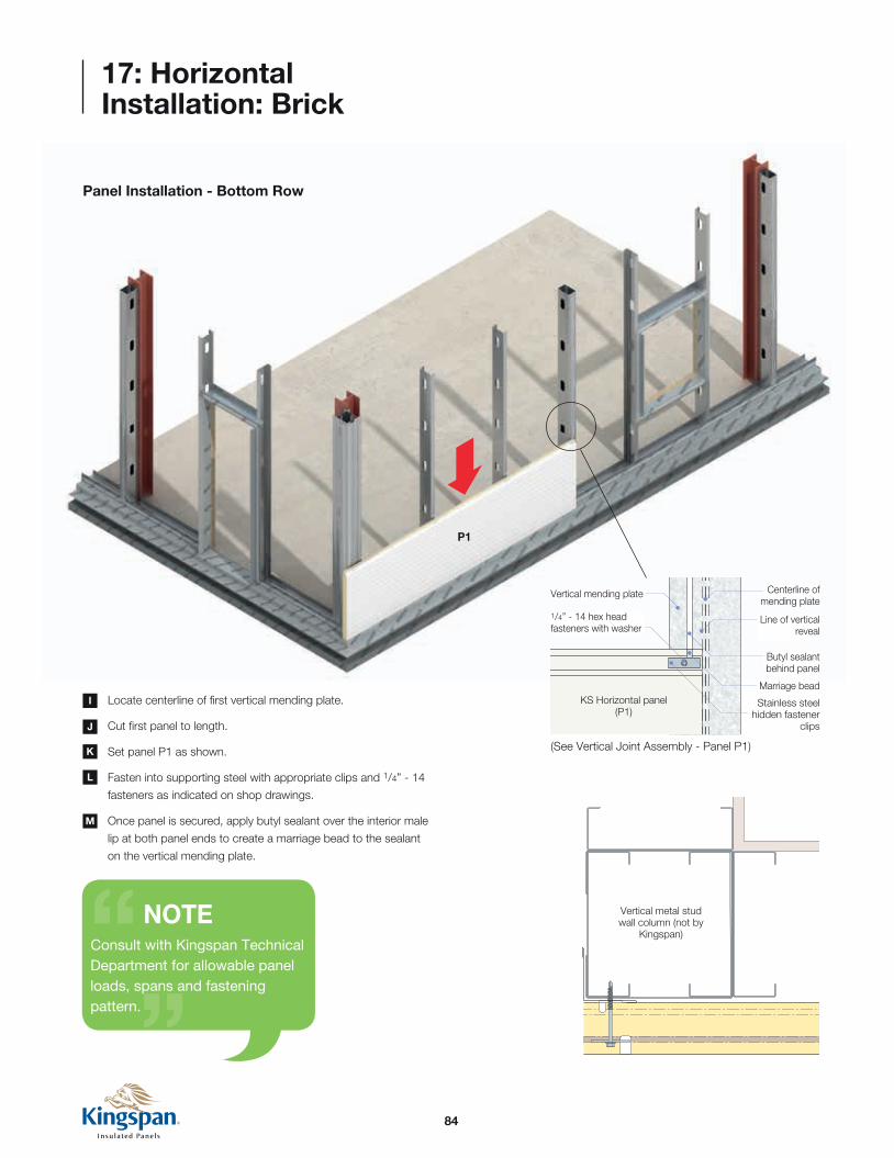
84
17: Horizontal Installation: Brick
Panel Installation - Bottom Row
Locate centerline of first vertical mending plate.
Cut first panel to length.
Set panel P1 as shown.
Fasten into supporting steel with appropriate clips and 1/4” - 14
fasteners as indicated on shop drawings.
Once panel is secured, apply butyl sealant over the interior male
lip at both panel ends to create a marriage bead to the sealant
on the vertical mending plate.
J
L
K
M
I
NOTEConsult with Kingspan Technical Department for allowable panel loads, spans and fastening pattern.
P1
Butyl sealant behind panel
Vertical mending plate
1/4” - 14 hex head fasteners with washer
KS Horizontal panel(P1)
Marriage bead
Line of vertical reveal
Centerline of mending plate
Stainless steel hidden fastener
clips
(See Vertical Joint Assembly - Panel P1)
Vertical metal stud wall column (not by
Kingspan)

85
Metal Jamb Flashing
12 GA. stainless steel hidden fastener clip with 1/4” -14 Hex head fastener
without washer (1 per panel, per support) set clip in butyl sealant
Metal jamb flashing (set in butyl sealant)
1/4” -14 through fastener with 1/8” bonded washer (as
required for wind load)
Sill flashing
Horizontal Kingspan panel
P2
P1
17: Horizontal Installation: Brick
Panel Installation - Bottom Row
Place panel P2 in position. Verify that the vertical edge of the
panel is lined up with the centerline of the mending plate.
Panel to slide into J trim at framed opening locations.
N
O
NOTECut panels in field as necessary for framed openings (see section 9).
(See Vertical Joint Assembly - Panel P1)
Butyl sealant behind panel
Vertical mending plate
KS Horizontal panel(P1)
KS Horizontal panel(P2)
Marriage beads
Line of vertical reveal
Centerline of mending plate
Stainless steel hidden fastener
clips1/4” - 14 hex head fasteners with washer
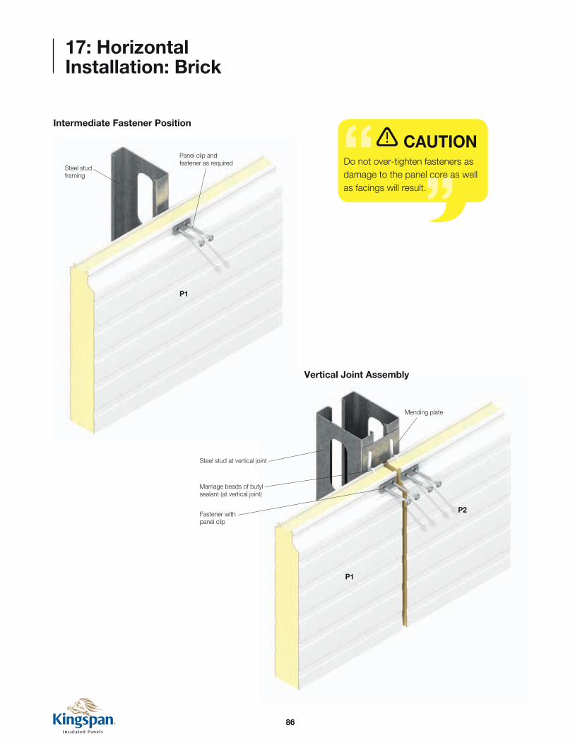
86
17: Horizontal Installation: Brick
CAUTIONDo not over-tighten fasteners as damage to the panel core as well as facings will result.
Intermediate Fastener Position
Panel clip and fastener as required
Steel stud framing
Fastener with panel clip
Marriage beads of butyl sealant (at vertical joint)
Steel stud at vertical joint
Mending plate
P1
P1
P2
Vertical Joint Assembly
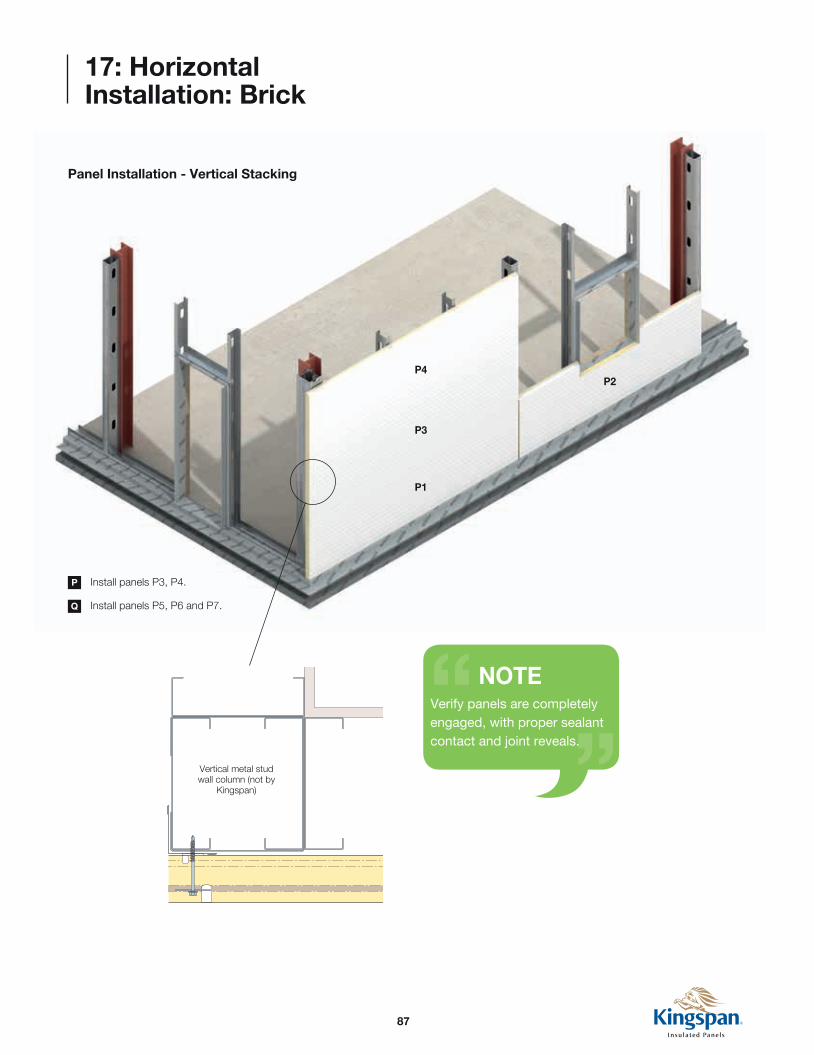
87
17: Horizontal Installation: Brick
Panel Installation - Vertical Stacking
Install panels P3, P4.
Install panels P5, P6 and P7.
P
Q
NOTEVerify panels are completely engaged, with proper sealant contact and joint reveals.
Vertical metal stud wall column (not by
Kingspan)
P1
P3
P4P2

88
P8
P9
P7
P1
P3
P4P2
P6
P5
P10
P11
P12
Assembly Sequence
17: Horizontal Installation: Brick
Vertical metal stud wall column (not by
Kingspan)
Self adhering membrane (not by Kingspan)
Break metal flashing
Set panel in butyl sealant with marriage bead to panel joint
12 GA. stainless steel hidden fastener clip (1 per panel, per support) set clip in butyl sealant
Fill horizontal panel reveal with butyl sealant and marriage bead to exterior panel joint
Metal Jamb Flashing
12 GA. stainless steel hidden fastener clip (1 per panel, per support) set clip in butyl sealant
Continuous butyl sealant at panel joints
12 GA. stainless steel hidden fastener clip with 1/4” -14 Hex head fastener
without washer (1 per panel, per support) set clip in butyl sealant
Metal jamb flashing
(set in butyl sealant)
1/4” -14 through fastener with 1/8” bonded washer
(as required for wind load)
Once the first elevation is completed (P1-P7), start around the
corner on next elevation using the same sequence and method
for P8-12.
Install outside corner trims as required.
R
S
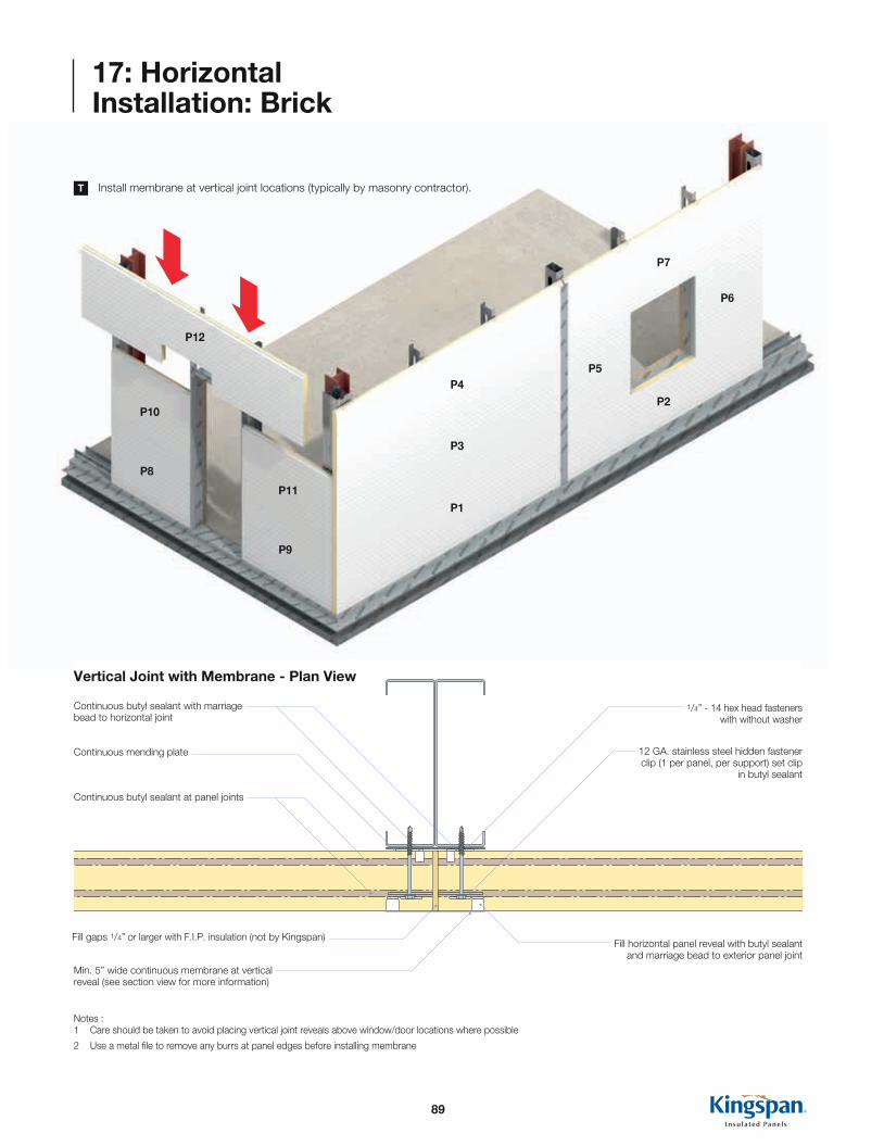
89
P8
P9
P7
P1
P3
P4P2
P6
P5
P10
P11
P12
Continuous butyl sealant at panel joints
Continuous butyl sealant with marriage bead to horizontal joint
Fill gaps 1/4” or larger with F.I.P. insulation (not by Kingspan)
Min. 5” wide continuous membrane at vertical reveal (see section view for more information)
Continuous mending plate
1/4” - 14 hex head fasteners with without washer
12 GA. stainless steel hidden fastener clip (1 per panel, per support) set clip
in butyl sealant
Fill horizontal panel reveal with butyl sealant and marriage bead to exterior panel joint
Notes :1 Care should be taken to avoid placing vertical joint reveals above window/door locations where possible
2 Use a metal file to remove any burrs at panel edges before installing membrane
Vertical Joint with Membrane - Plan View
17: Horizontal Installation: Brick
Install membrane at vertical joint locations (typically by masonry contractor).T

90
17: Horizontal Installation: Brick
Panel Jamb Membrane
Panel Jamb/Sill Membrane
Membrane jamb flashing
Membrane corner flashing
Verify masonry contractor has installed jamb and sill wraps, sill
pans as shown.
U
DisclaimerALL membrane and brick details shown here are informational only, and are provided to show typical interfaces and sequence of installation between the panel system and other materials.Consult the architect’s drawings or masonry contractor’s approved shop drawings for project specific details.

91
17: Horizontal Installation: Brick
Panel Sill Membrane
Jamb Membrane
Membrane flashing with upturned ends to form end dams (by Mason)
Membrane jamb flashing

92
17: Horizontal Installation: Brick
KingTies Fastened Into Panel Supports
Install KingTie - HB wing nut with pintle to
masonry (spacing to be determined by the
engineer of record).
Lay bricks on base membrane inserting
KingTies as required.
Panels are now ready to receive brick system (by masonry contractor). V

93
17: Horizontal Installation: Brick
Base Layering - Typical
Vertical metal stud wall (not Kingspan)
Mortar net (not Kingspan)
Drip flashing (not by Kingspan)
Horizontal Kingspan panel
Face brick (by Mason)
12 GA. Stainless steel hidden fastener clip with 1/4” - 14 hex head fastener without washer (1 per panel, per support) set clip in butyl sealant
Flexible membrane
flashing (not by Kingspan)
Brick tie-HB wing nut 2-seal with Pintle (spacing to be determined by the engineer of record)
1/4” -14 through fasteners with 11/8” bounded washer (as required for wind load)
Flexible membrane flashing (not by Kingspan)
Masonry filler block (not by Kingspan)
Metal base channel (not by Kingspan)
Concrete slab & foundation (not by
Kingspan)Note:1 Use a metal file to remove any burrs at panel edges before installing membrane
2 Architect and/or contractor must verify compatibility of membrane materials with adjoining sealant materials
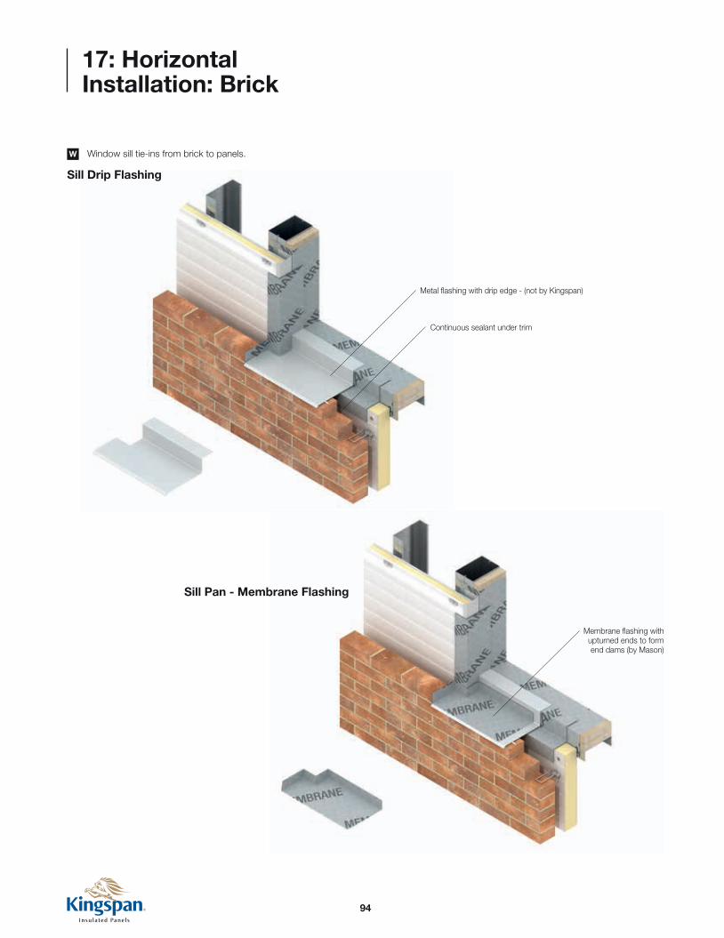
94
17: Horizontal Installation: Brick
Sill Drip Flashing
Sill Pan - Membrane Flashing
Continuous sealant under trim
Membrane flashing with upturned ends to form end dams (by Mason)
Metal flashing with drip edge - (not by Kingspan)
Window sill tie-ins from brick to panels.W
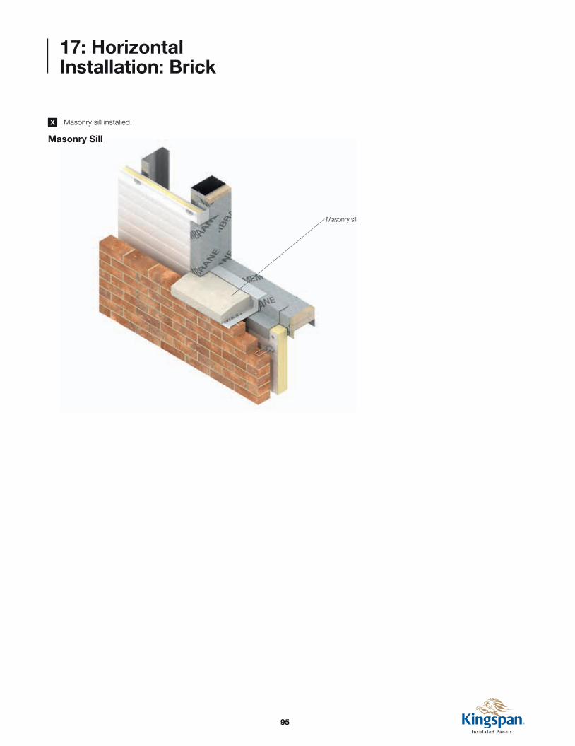
95
17: Horizontal Installation: Brick
Masonry sill
Masonry Sill
Masonry sill installed. X

96
17: Horizontal Installation: Brick
Completed Window Sill/Jamb Assembly - Typical
Vertical metal stud wall (not by Kingspan)
Metal jamb flashing (set in butyl sealant)
Brick tie-HB wing nut 2-seal with Pintle (spacing to be determined by the engineer of record)
Masonry sill
Set flashing in continuous sealant (by Mason)
Membrane flashing with upturned ends to form end dams (by Mason)
Membrane flashing with upturned ends to form end
dams (by Mason)
Self adhering vapour barrier at window rough opening
(not by Kingspan)
1/4” -14 through fasteners with 11/8” bounded washer
(as required for wind load)
Self adhering vapour barrier at window rough opening (not by Kingspan)
Metal flashing with drip edge
Membrane jamb flashing
Face brick (not by Kingspan)
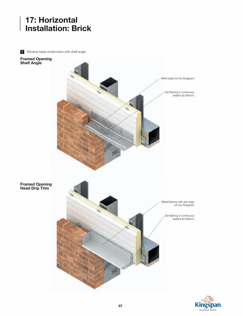
97
17: Horizontal Installation: Brick
Framed Opening Shelf Angle
Framed Opening Head Drip Trim
Shelf angle (not by Kingspan)
Set flashing in continuous sealant (by Mason)
Metal flashing with drip edge (not by Kingspan)
Set flashing in continuous sealant (by Mason)
Window head construction with shelf angle.Y

98
17: Horizontal Installation: Brick
Framed Opening Header Flashing
Self adhering membrane with upturned ends to form end
dams (by Mason)

99
17: Horizontal Installation: Brick
Completed Window Sill/Jamb Assembly - Typical
Self adhering vapour barrier at window rough opening
(not by Kingspan)
Self adhering membrane with upturned ends to form end
dams (by Mason)
Mortar net (not by Kingspan)
Membrane termination bar, fasteners and sealant (by Mason)
12 GA. Stainless steel hidden fastener clip with 1/4” - 14 hex head fastener without washer (1 per panel, per support) set clip in butyl sealant
Set flashing in continuous
sealant (by Mason)
Set panel in continuous butyl sealant
Shelf angle (not by Kingspan)
Brick (not by Kingspan)
1/4” -14 through fasteners with 11/8” bounded washer
(as required for wind load)
Vertical metal stud wall (not by Kingspan)
Brick tie-HB wing nut 2-seal with Pintle (spacing to be determined by the engineer of record)
Metal flashing with drip edge
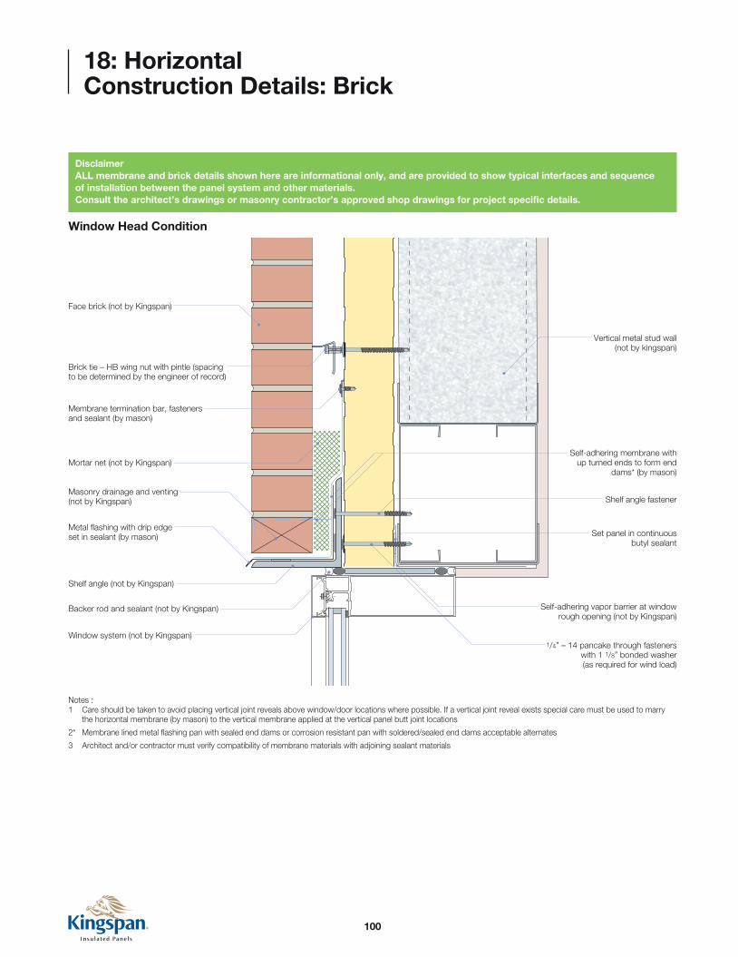
100
18: Horizontal Construction Details: Brick
Window Head Condition
1/4” – 14 pancake through fasteners with 1 1/8” bonded washer (as required for wind load)
Face brick (not by Kingspan)
Masonry drainage and venting (not by Kingspan)
Metal flashing with drip edge set in sealant (by mason)
Backer rod and sealant (not by Kingspan)
Shelf angle (not by Kingspan)
Window system (not by Kingspan)
Self-adhering vapor barrier at window rough opening (not by Kingspan)
Mortar net (not by Kingspan)
Vertical metal stud wall (not by kingspan)
Membrane termination bar, fasteners and sealant (by mason)
Set panel in continuous butyl sealant
Shelf angle fastener
Self-adhering membrane with up turned ends to form end
dams* (by mason)
Brick tie – HB wing nut with pintle (spacing to be determined by the engineer of record)
Notes :1 Care should be taken to avoid placing vertical joint reveals above window/door locations where possible. If a vertical joint reveal exists special care must be used to marry the horizontal membrane (by mason) to the vertical membrane applied at the vertical panel butt joint locations
2* Membrane lined metal flashing pan with sealed end dams or corrosion resistant pan with soldered/sealed end dams acceptable alternates
3 Architect and/or contractor must verify compatibility of membrane materials with adjoining sealant materials
DisclaimerALL membrane and brick details shown here are informational only, and are provided to show typical interfaces and sequence of installation between the panel system and other materials.Consult the architect’s drawings or masonry contractor’s approved shop drawings for project specific details.

101
18: Horizontal Construction Details: Brick
Window Head Condition (alternate - vertical panel joint located above window)
Continuous mending plate
Continuous butyl sealant at vertical panel butt joint
Membrane terminator bar, fastener and sealant (by mason)
Vertical metal stud wall (not by Kingspan)
Min. 5” wide continuous membrane at vertical reveal
Continuous butyl sealant at both panel joints
Fill horizontal panel reveal with butyl sealant and marriage bead to exterior panel joint
Install clip/fastener at panel ends prior to installation of membrane
Min. 5” wide membrane at vertical reveal (see vertical panel joint - section) lap Min. 3” vertically onto mending plate
3” M
in. l
ap
Self adhering membrane with upturned ends to form end dams (by mason) - see window header detail
Self adhering membrane with upturned ends to form end dams (by mason) see window header detail
Membrane termination bar, fasteners and sealant (by mason)
Notes :1 Brick and panel fastening not shown for clarity

102
18: Horizontal Construction Details: Brick
Window Jamb Condition
Window Sill Condition
Window system (not by Kingspan)
Metal jamb flashing (set in butyl sealant)
Backer rod and sealant (not by Kingspan)
Fill horizontal panel reveal with butyl sealant and marriage bead to exterior panel joint
12 GA. stainless steel hidden fastener clip (1 per panel, per support) set clip in butyl sealant
1/4” - 14 hex head fasteners with without washer
Set panel in butyl sealant with marriage bead to panel joint
Self adhering membrane (not by Kingspan)
Continuous butyl sealant at panel joints
Brick tie - HB wing nut with pintle (spacing to be determined by the engineer of record)
Facing brick (not by Kingspan) Self adhering membrane with transition to end dams at sill
below (not by Kingspan)Notes :1 Use a metal file to remove any burrs at panel edges before installing membrane2 Architect and/or contractor must verify compatibility of membrane materials with adjoining sealant materials
1/4” - 14 pancake through fasteners with 11/8” bonded washer (as required for wind load)
Window system (not by Kingspan)Self adhering membrane
(not by Kingspan)
Backer rod and sealant (not by Kingspan)
Membrane flashing with upturned ends to form end dams (by mason)
Metal flashing with drip end set in sealant (by mason)
Set panel in continuous butyl sealant
Brick tie - HB wing nut with pintle (spacing to be determined by the engineer of record)
Facing brick (not by Kingspan)

103
18: Horizontal Construction Details: Brick
Base Condition - Typical
Note:1 Use a metal file to remove any burrs at panel edges before installing membrane
2 Architect and/or contractor must verify compatibility of membrane materials with adjoining sealant materials
Vertical metal stud wall (not Kingspan)
Mortar net (not Kingspan)
Horizontal Kingspan panel
Face brick (by Mason)
12 GA. Stainless steel hidden fastener clip with 1/4” - 14 hex head fastener without washer (1 per panel, per support) set clip in butyl sealant
Flexible membrane
flashing (not by Kingspan)
Brick tie-HB wing nut 2-seal with Pintle (spacing to be determined by the engineer of record)
1/4” -14 through fasteners with 11/8” bounded washer (as required for wind load)
Flexible membrane flashing (not by Kingspan)
Masonry filler block (not by Kingspan)
Metal base channel (not by Kingspan)
Concrete slab & foundation (not by
Kingspan)
Drip flashing (not by Kingspan)

104
18: Horizontal Construction Details: Brick
Vertical Transition
Notes :1 Use a metal file to remove any burrs at panel edges before installing membrane
2 Architect and/or contractor must verify compatibility of membrane materials with adjoining sealant materials
Metal ‘J’ flashing
Set panel in butyl sealant with marriage bead to panel joint
Fill horizontal panel reveal with butyl sealant and marriage bead to exterior panel joint
Continuous butyl sealant at panel joints
Self adhering membrane (not by Kingspan)
Brick tie - HB wing nut with pintle (spacing to be determined by the engineer of record)
Facing brick (not by Kingspan)
1/4” - 14 hex head fasteners without washer
12 GA. stainless steel hidden fastener clip (1 per panel, per support) set clip in butyl sealant
Backer rod and sealant (not by Kingspan)
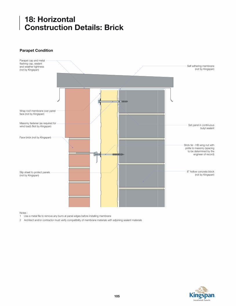
105
18: Horizontal Construction Details: Brick
Parapet Condition
Parapet cap and metal flashing cap, sealant and weather tightness (not by Kingspan)
Wrap roof membrane over panel face (not by Kingspan)
Masonry fastener (as required for wind load) (Not by Kingspan)
Face brick (not by Kingspan)
Slip sheet to protect panels (not by Kingspan)
Notes :1 Use a metal file to remove any burrs at panel edges before installing membrane
2 Architect and/or contractor must verify compatibility of membrane materials with adjoining sealant materials
Self adhering membrane (not by Kingspan)
Set panel in continuous butyl sealant
Brick tie - HB wing nut with pintle to masonry (spacing
to be determined by the engineer of record)
8” hollow concrete block (not by Kingspan)

106
18: Horizontal Construction Details: Brick
Expansion Joint - horizontal
Face brick (by mason)
1/4” - 14 through fasteners with 11/8” bonded washer (as required for wind load)
1/4” - 14 through fasteners with 11/8” bonded washer (as required for wind load)
Mortar net (not by Kingspan)
Self adhering membrane (not by Kingspan)
Masonry drainage and venting (by mason)
Metal flashing with drip edge set in sealant (by mason)
Backer rod and sealant (not by Kingspan)
Flexible membrane flashing (not by Kingspan)
Flexible membrane flashing (not by Kingspan)
Flexible membrane flashing (not by Kingspan)
Set panel in continuous butyl sealant
Set panel in continuous butyl sealant
Vertical metal stud wall (not by Kingspan)
Rigid insulation (not by Kingspan)
Shelf angle (not by Kingspan)
Shelf angle concrete fastener
Slip track (not by Kingspan)
Compressible insulation (not by Kingspan)
Brick tie - HB wing nut with pintle (spacing to be determined by the engineer of record)

107
19: Fastener Information
Chart based on data from fastener manufacturers laboratory test
results. Since actual job site conditions will vary, chart is a basic
guideline. If in doubt, field drilling and pull tests are recommended.
If #14 type ‘B’ plated fasteners are to be used, pre-drilling is
required. Use the drill bit sizes listed below.
Suggested Fastener Driving SpeedsQuarter inch diameter self drilling, self tapping TEK type and B point
self tapping type.
Note: Proper tools are required to produce consistent drilling and minimize potential fastener or application failures due to over or under driven fasteners. A torque control or depth sensing nose piece for the screw gun is recommended for proper installation.
Carbon and 410 Stainless 1,800 rpm
Stainless 1,000 rpm
Recommended TEK type for 1/4” diameter (self-drilling, self tapping) fasteners
Steel Thickness TEK Threads/inch16 Ga. (.060) #2, #3 14
14 Ga. (.075) #2, #3 14
12 Ga. (.105) #3 141/8” (.125) #3 14
10 Ga. (.134) #3 143/16” (.187) #3 141/4” (.250) #3, #5 14 (#3) / 20 minimum (#5)3/8” (.375) #5 20 minimum1/2” (.500) #5 20 minimum
Pilot hole chart for 1/4” diameter B Point fasteners (self tapping)
Steel Thickness Drill Size16 Ga. (.060) #8 (.199)
14 Ga. (.075) #7 (.201)
12 Ga. (.105) #7 (.201)1/8” (.125) #2 (.221)
10 Ga. (.134) #2 (.221)3/16” (.187) #2 (.221)1/4” (.250) #2 (.221)3/8” (.375) #2 (.221)1/2” (.500) #1 (.228)

108
19: Fastener Information
To install type ‘B’ fastener, pre-drill using the correct drill size from
chart on previous page. Insert fastener through KarrierRail™ and
tighten down until assembly is snug. Panels are to be fastened at
every support. Fastener requirements are based on design loads.
Consult Kingspan Technical Services for allowable panel and
fastener design loads.
Do not use impact tools. Do not over tighten.
After drilling always remove metal chips that
ave fallen onto flashings or panels.
NOTEThe rail replaces the use of individual panel clips, and should be fastened with two fasteners at every structural location. Expansion fasteners or similar must be used to attached the exposed edge of the KarrierRail™ to the panel face, with spacing determined by Kingspan’s Technical Services department.
NOTEContact Kingspan’s Technical Services Department for specific project fastening recommendations.
2”-6
”
KS42SL (Shadowline) Panel
42” Coverage (36”, 30” & 24” optional)
Shadowline
ShadowlineExterior face
Interior face
1/4” - 14 Hex head fasteners with washer
Continuous Karrier™ (KarrierRail™ available
in 1 - 3” faces)
KarrierRail™

109
KarrierPanel™ with Brick
19: Fastener Information
To install type ‘B’ fastener, pre-drill using the correct drill size from
chart on previous page. Insert fastener through clip and tighten
down until assembly is snug. Panels are to be fastened at every
support. Fastener requirements are based on design loads. Consult
Kingspan Technical Services for allowable panel and fastener design
loads. Do not use impact tools. Do not over tighten.
After drilling always remove metal chips that have fallen onto
flashings or panels.
NOTEContact Kingspan’s Technical Services Department for specific project fastening recommendations.
1/4” - 14 Hex head fasteners with washer
Stainless steel hidden fastener clip (1 per panel, per support)
set clip in butyl sealant
Standard: Stainless steel two-hole hidden fastener clip
Optional: Stainless steel one-hole hidden fastener clip
5/16” Ø
3/4”1”
21/4”
5/16” Ø
3/4”21/4”

110
20: Materials, Tools & Hardware
Tools and Sealants
Fastening Hardware
Electric snips Circular saw with fine tooth carbide blade
Power nibbler Power drill Drive bits and sockets
Expandable foam Caulking gun Laser or gravity levelers Grip clamp
Primary fastener Through fastener (primary fastener extended by 1”)
Low profile fastener Secondary fastener
Brick Tie (KingTie)
Rivet fastener
Hidden fastener wall panel clip
KarrierRail™
Knife and Scraper

111
Notes

11/2017
USADeLand, FL 877-638-3266
Modesto, CA 800-377-5110
Columbus, OH 888-332-5862
CanadaCaledon, ON 866-442-3594
Langley, BC 877-937-6562
For the product offering in other markets please contact your local sales representative or visit www.kingspanpanels.com
Care has been taken to ensure that the contents of this publication are accurate, but Kingspan Limited and its subsidiary companies do not accept responsibility for errors or for information that is found to be misleading. Suggestions for, or description of, the end use or application of products or methods of working are for information only and Kingspan Limited and its subsidiaries accept no liability in respect thereof.