Installation Guide...Installation Guide 3 Introduction This booklet will answer the needs of pipe...
42
PVC PIPE FOR HDD & OTHER TRENCHLESS APPLICATIONS MUNICIPAL SYSTEMS We Build Tough Products for Tough Environments ® Installation Guide
Transcript of Installation Guide...Installation Guide 3 Introduction This booklet will answer the needs of pipe...

PVC PIPE FOR HDD & OTHER TRENCHLESS APPLICATIONS
M U N I C I P A L S Y S T E M S
We Build Tough Products for Tough Environments®
Installation Guide

Installation Guide 1
TABLE OF CONTENTS
Introduction . . . . . . . . . . . . . . . . . . . . . . . . . . . . . . . . . . . . . . . . . . . . 3
Terrabrute® CR PVC Pipe for HDD & Other Trenchless Applications 6
Pull Strength . . . . . . . . . . . . . . . . . . . . . . . . . . . . . . . . . . . . . . . . . . 6Applications . . . . . . . . . . . . . . . . . . . . . . . . . . . . . . . . . . . . . . . . . . 6
Standards and Specifications 7
Dimensions 7Minimum Bending Radius – TerraBrute® CR Pipe . . . . . . . . 8Joint Deflection Radius & Minimum Allowable Radius . . . . 8Maximum Allowable Pull Force . . . . . . . . . . . . . . . . . . . . . . . . . 8
Joint Assembly Instructions 9
Additional Considerations for Trenchless Installations with PVC 14
Pull Head 14
Cutting Pipe 17
Accessories 19
Restrainers 19
Service Connections 20Tapping . . . . . . . . . . . . . . . . . . . . . . . . . . . . . . . . . . . . . . . . . . . . . 20
Pressure Testing Procedures 23Basis for Hydrostatic Pressure Test . . . . . . . . . . . . . . . . . . . . 24Preparations for the Hydrostatic Pressure Test . . . . . . . . . 25Determination of Test Pressure . . . . . . . . . . . . . . . . . . . . . . . 27Steps of the Hydrostatic Pressure Test . . . . . . . . . . . . . . . . 27Procedures for Gravity Sewer Testing . . . . . . . . . . . . . . . . . 29Above Grade Testing . . . . . . . . . . . . . . . . . . . . . . . . . . . . . . . . 29Hydrostatic Pressure Testing . . . . . . . . . . . . . . . . . . . . . . . . . . 30Drill Stem . . . . . . . . . . . . . . . . . . . . . . . . . . . . . . . . . . . . . . . . . . . . 32

2 Installation Guide
NovaFormTM PVC Liner for Sewer & Culverts 35
Standards & Specifications 36Material . . . . . . . . . . . . . . . . . . . . . . . . . . . . . . . . . . . . . . . . . . . . . 36
Extruded Pipe . . . . . . . . . . . . . . . . . . . . . . . . . . . . . . . . . . . . . . . 36
Marking . . . . . . . . . . . . . . . . . . . . . . . . . . . . . . . . . . . . . . . . . . . . . 36
Colour Coding . . . . . . . . . . . . . . . . . . . . . . . . . . . . . . . . . . . . . . . 37
Packaing . . . . . . . . . . . . . . . . . . . . . . . . . . . . . . . . . . . . . . . . . . . . 37
Pipe Data 37Weather Conditions . . . . . . . . . . . . . . . . . . . . . . . . . . . . . . . . . . 37
Installation 38

Installation Guide 3 Installation Guide 3
Introduction
This booklet will answer the needs of pipe installers looking for general recommendations on how to install TerraBrute® CR and NovaFormTM pipes . Out-of-the-ordinary conditions not covered here should be referred to the engineer or field inspectors to provide on-site solutions . In such cases IPEX’s advice is always available . Our objective is to encourage the use of methods that lead to a professional installation that will ensure the maximum service life for the pipe .
The Engineer who designs the pipeline will determine how it is to be installed . It is not our intention that the Guide should assume that responsibility unless the Engineer so directs .
This booklet is an addition to our “Pressure Pipe Installation Guide” and “Sewer Pipe Installation Guide” and sets out the preferred methods of installation based on IPEX’s experience and on a number of published reports from other industry sources . Users will find additional helpful advice in “Recommended Practice for the Installation of PVC Pressure Pipe”, AWWA C605, published by the American Water Works Association .
Readers are invited to order a copy of the PVC Pipe Association Handbook of PVC Pipe - Design and Construction 5th Edition” (Hardcover Published December 2012) . This comprehensive reference manual, with over 600 pages, covers all aspects of design and installation for PVC pipe & fittings .
Visit uni-bell .org to order .

4 Installation Guide
NOTES
Installation Guide 5 Installation Guide 5
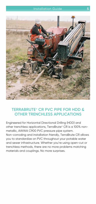
TERRABRUTE® CR PVC PIPE FOR HDD & OTHER TRENCHLESS APPLICATIONS
Engineered for Horizontal Directional Drilling (HDD) and other trenchless applications, TerraBrute® CR is a 100% non-metallic, AWWA C900 PVC pressure pipe system . Non-corroding and installation friendly, TerraBrute CR allows you to standardize on PVC throughout your potable water and sewer infrastructure . Whether you’re using open-cut or trenchless methods, there are no more problems matching materials and couplings . No more surprises .

6 Installation Guide
Pull Strength
Developed in consultation with leading trenchless technology research experts, and rigorously tested in the field, TerraBrute CR trenchless PVC pressure pipe easily withstands the high tensile and bending forces that occur during HDD and other types of trenchless installation .
TerraBrute CR’s patented non-metallic “ring-and-pin” gasketed joint design outperforms all other restrained PVC pipe joints on the market, providing more than twice the pull strength of other HDD systems – up to 120,000 lbs . (Ultimate) for 300mm / 12" pipe . Unlike competing square-shoulder designs, TerraBrute CR’s rounded bell shoulders slide by roots, rocks and other debris that can protrude into the borehole . And unlike HDPE, TerraBrute CR requires no relaxation time before installation of fittings or services .
TerraBrute CR is an integral bell restrained joint PVC pipe . It is AWWA C900 pipe with slight modification that allows the joints to be locked, and the pipe used for “pulled in place” applications like horizontal directional drilling (HDD) or pipe bursting .
TerraBrute CR’s patented locking system allows pipe to be assembled one length at a time, thus minimizing disturbance to the surrounding area and making TerraBrute CR the ideal choice for HDD projects located in tight areas .
Applications
TerraBrute pipes can be installed for the following:
• Horizontal Directional Drilling (HDD)
• Pipe Bursting
• Bridge Crossings
• Seismic Zones
• Casing
• Steep Slopes
This manual covers general installation recommendations as well as application specific recommendations .

Installation Guide 7 Installation Guide 7
STANDARDS AND SPECIFICATIONSCodes and standards applicable to the products with description of the products covered .
AWWA C900: TerraBrute CR is made with pipe conforming to AWWA C900 . However once the pipe is grooved on the spigot end its dimensions do not match those published in the C900 standard . Because of this small dimensional difference the pipe, once grooved, does not strictly conform to the C900 standard . It is important to note however, that TerraBrute CR is subjected to the same testing program as IPEX’s Blue Brute (C900) pipe .
CSA B137 .3: TerraBrute CR is certified to CSA B137 .3,
NQ 3660-950 NSF
Factory Mutual, Underwriter’s Laboratories and BNQ: TerraBrute CR is made from pipe that is Factory Mutual FM1612 Approved, ULC/UL 1285 Listed and BNQ NQ 3624-250 Certified .
DIMENSIONS
When planning an HDD or pipe bursting project with TerraBrute CR, it must be remembered that it is a gasketed cast iron outside diameter (CIOD) pipe . This means that it will have a larger outside diameter than an IPSOD HDPE pipe of the same nominal size . In addition, the bell is the largest diameter on the pipe and must be accounted for when planning pre-ream operations .
Dimensions
Nominal Diameter
Pressure Rating (2:1 safety factor)
Maximum OD
(Bell OD)
Average ID
mm in psi mm in mm in100 4 305 165 6 .49 104 4 .09150 6 305 230 9 .06 149 5 .87200 8 235 288 11 .33 204 8 .03 250 10 235 355 14 .00 250 9 .84300 12 235 416 16 .36 297 11 .69

8 Installation Guide
Maximum Allowable Bending – TerraBrute® CR Pipe Allowable Pipe Bending (Degrees)
& Allowable Pipe Joint Deflection (Degrees)
Nominal Size Allowable Pipe Bending (Degrees)
Allowable Pipe Joint Deflection
(Degrees)Total
mm in
100 4 5 .7 8 .5 14 .2
150 6 4 8 .5 12 .5
200 8 3 7 .5 10 .5
250 10 2 .5 5 7 .5
300 12 2 .1 5 7 .1
Joint Deflection Radius & Minimum Allowable Radius
Joint Deflection Radius * Min . Allowable Radius **
m ft m ft
40 .4 132 .7 24 .2 79 .4
40 .4 132 .7 27 .5 90 .2
45 .8 150 .3 32 .7 107 .4
68 .8 225 .5 45 .8 150 .3
68 .8 225 .5 48 .4 158 .8
* Bending radius with joint deflection only (no bending)
** Joint deflection and pipe bending
Maximum Allowable Pull Force
Nominal Size Allowable* Pulling Force
mm in kN lbs
100 4 50 11200
150 6 110 24700
200 8 115 25800
250 10 187 .5 42100
300 12 275 61800
*Using a 2:1 Safety Factor

Installation Guide 9 Installation Guide 9
JOINT ASSEMBLY INSTRUCTIONS
The TerraBrute CR locking mechanism has been designed for easy installation . In fact, it is not much different than assembling a standard C900 joint .
General Recommendations:
Pipe joints should be assembled using manual effort wherever possible . However if mechanical assistance is required, a pipe stop should be used to prevent over insertion . This can be easily accomplished by installing a standard restrainer grip ring or a clamp aligned with the insertion line on the spigot .
1 Locate the insertion line on the spigot end of each pipe . If the line is missing, it can be marked as follows . (see chart below)
Insertion LineL
Pipe Size Insertion Line Depth (L)
mm in mm in
100 4 195 7 .7
150 6 218 8 .6
200 8 253 10 .0
250 10 268 10 .6
300 12 293 11 .5

10 Installation Guide
2 Lube the spigot and gasket as you normally would when assembling a standard C900 joint .
3 Using a bar and block for smaller sizes (4" - 8") or mechanical means for larger sizes, line up the two pipes in a straight line and push the spigot into the bell . The pipe should be pushed until the line marked on the spigot is aligned with the end of the bell . Care must be taken not to over-insert the pipe as the locking pins may not line up with the inner groove .
While this can be easily controlled when using manual effort, it can be more difficult when using mechanical means such as a backhoe . In these cases it is recommended that a “pipe stop” be installed on the insertion line to prevent over insertion . A standard restrainer ring that can be removed after assembly will accomplish this .

Installation Guide 11 Installation Guide 11
4 Once the holes on the bell are aligned with the inner groove, line up the pins on the external half ring with the holes in the bell so that the half ring covers either the left or right side of the pipe .
SAFETY GLASSES MUST BE WORN DURING PIN
CAUTION
SAFETY GLASSESREQUIRED

12 Installation Guide
INSTALLATION .
5 Using a 1 lb hammer, tap in the pins starting at the top of the pipe working your way down . The pins should be tapped until they bottom out on the inner groove or are flush with the ring . A good technique to ensure proper alignment, is to tap each pin on the ring 1/4 to 1/2 of the way in before hammering in fully . If the pins will not go all the way in, check to see if the rings, holes, and inner groove are properly aligned on all sides .
6 Check to make sure all of the pins are fully inserted before starting the next joint .

Installation Guide 13
ATTENTION
Installation Guide 13
ExternalRing
Pin must be bottomed out on groove
Insertion Line
Hole in Bell
InnerGroove
InnerGroove
Ensure the inner groove is completely aligned with holes before inserting pins . All pins must be bottomed out on the inner groove after insertion .
When connecting to standard C900 pipe or fittings, cut off grooved portion and chamfer pipe edges as shown in the Installation Manual . DO NOT use the TerraBrute CR insertion mark as a guide for insertion into standard pipe or fittings – it is designed for the extended bell of TerraBrute CR .

14 Installation Guide
ADDITIONAL CONSIDERATIONS FOR TRENCHLESS INSTALLATIONS WITH PVC
PULL HEAD
A proper pull head, designed to the specification of the pipe and to achieve the maximum allowable pull force recommendation is required . A conceptual design is available on demand .
In HDD installations it is important for the pull head to be water tight in order to prevent the drilling fluid from coming in or the ballast water from seeping out .
Pulling Head Installation and Pipe End Sealing
Product Use Warnings
• Connections to the pull head clevis should be such that the pull head and the attached pipe are NOT allowed to rotate .
• The pull head clevis should NOT be modified to fit a non-compatible pulling mechanism .
• Components of the pulling mechanism, such as sub-assemblies, swivels, clasps and pins that will be located between the pull head and the pulling mechanism must be rated at or above the allowable pulling force for the TerraBrute CR pipe sections being installed .
Pull Head Sealing Pipe End
3) Seal pull headSeal all holes withwashers and/orsilicon caulking
Washers
Seal End
Through bolts withsmooth shank
2) Use plastic and tape
1) Install sewer plugAttach tether fromplug to pull head
Listed in orderof preference:
• Use pulling head to achieve maximum allowable pull force recommendation for the pipe
• Do not exceed maximum recommended allowable pull force for the given pipe selection

Installation Guide 15 Installation Guide 15
• NEVER exceed the maximum allowable pull force for the TerraBrute CR pipe being installed .
• The end of the pipe being installed should be sealed prior to installation of the pull head to minimize the amount of foreign substance entering the interior of the pipe during pull-in . (see “Installing the Pull Head”)
Installing the Pull Head
1 . CAUTION: Some pull heads are not designed to stop the drilling mud or other liquids from entering the pipe . Seal the end of the pipe using one of the following methods in order of most preferable to least preferable:
a . Insert a clean inflatable sewer plug into the end of the pipe ensuring that the plug has been inserted deeper than the deepest bolt holes . Inflate the plug until it seals with the inside of the pipe and tie off the plug to a cross bolt for easy retrieval . For extra sealing, follow step b or c below . Go to step 2 .
b . If a clean sewer plug is not available, use a piece of thick plastic (possibly a garbage bag) and “Gorilla Tape” to seal the end of the pipe . The plastic or bag should be slid onto the end of the pipe and taped to the outer diameter of the pipe . Taping should then be done as shown in the diagram to seal the pipe-end as much as possible . Got to step 2 .
c . If “Gorilla Tape” is not available, a minimum of 10 .5 ml duct tape can be used . However, duct tape is not ideal for this application . Go to step 2 .
2 . Measure the outside of the pull head for the barrel length of the pull head to be used . Be sure not to measure past the barrel of the pull head into the cone portion . Measure the same distance from the end of the pipe on which the pull head will be installed and mark the position with a line using the marker .
3 . Insert the pull head over the pipe until the pull head barrel reaches the general location of the line marked in step 2 . The pull head is heavy and designed with a tight clearance so proper equipment should be used to mount the pull head . It might be necessary to push the pull head on with a piece of equipment .

16 Installation Guide
4 . Use a sharp (preferably new) hole saw or drill bit to drill holes in the pipe using the holes in the pull head as a template . When drilling, it is important to allow the teeth of the hole saw to do the cutting – putting additional pressure on the drill during this step could damage the pipe .
5 . Cut the all thread stock to the proper size .
CAUTION: When cutting all thread it is possible for the threads to bend and not allow the installation of the smooth shank pull head nuts . Use the file to clean the threads and ensure that the pull head nuts can be threaded onto the all thread . Cross-threading will not give the proper amount of strength to the assembly and must be avoided . Each size pipe is different so care should be taken to ensure that the all thread will reach across the pipe .
NOTE: The all thread can always be trimmed but cannot be lengthened, so if there is any question as to the length, it is recommended that the all thread be cut longer than needed . If necessary, it can be cut again .
6 . After complete installation of all hardware, “Gorilla Tape” should be used to seal the pull head as much as possible . “Gorilla Tape” should be installed over the pull head nuts and wrapped entirely around the pull head . Duct tape may be used, but is not preferred and may not result in a complete seal .
7 . Use “Gorilla Tape” to seal off the edge of the pull head to the pipe in order to prevent (as much as possible) drilling mud leaking up the pull head .
NOTE: Silicone caulking can be used in concert with the “Gorilla Tape” to help seal the pull head . However, the caulking should only be used for sealing and cannot be used in lieu of the “Gorilla Tape . Again, duct tape may be used, but not preferable .
This process must be repeated for each individual pull . The pull head cannot be cut off and re-fused onto the end of the pipe as this could cause the pipe to fail at the pull head connections .
Please contact IPEX at 1-800-463-9572 with any questions regarding pull head installation or use .

Installation Guide 17 Installation Guide 17
CUTTING PIPE
Introduction
TerraBrute CR pipe is made to water and wastewater industry PVC piping standards . Like regular PVC pipe, generally recommended practices for working with and handling PVC pipe apply to TerraBrute CR pipe . However, lengths of TerraBrute CR pipe, are subject to stresses not generally experienced by standard 20 foot lengths of bell and spigot PVC pipe . These stresses are related to the configuration of the pipe and/or the method of installation . The purpose of this section is to provide recommendations regarding the proper procedures and requirements for cutting TerraBrute CR pipe .

18 Installation Guide
Management of ‘Pulling’ Energy
The installation of TerraBrute CR pipe, particularly trenchless installations, will result in residual energy in the pipe after the installation has been completed . Such residual energy is the result of pulling the pipe into position, taking advantage of the tensile capacity of the pipe and joint .
In order to minimize or relieve the residual energy from pulling, it is recommended that the lead end of the installed pipe length be pushed back gently in the reverse direction of the installation . This compressive force will act to relieve residual tension on the pipe after being pulled . Ideally, the back end of the installed pipe should move slightly, showing that the entire pipe string has been compressively moved back through the final installation alignment . While this is ideal, it may not be possible in certain circumstances and installations, such as HDD installations .

Installation Guide 19 Installation Guide 19
ACCESSORIES
TerraBrute CR pipes are made to the same dimensions as regular AWWA C900 and C905 PVC pipe and can be used with the same fittings and accessories . Fused joints are fully restrained and do not require mechanical restraints; however, both ends of a fused string of pipe must be restrained to the system it ties into .
RESTRAINERS
TerraBrute CR pipe to a bell and spigot system
TerraBrute CR products offer a fully restrained joint once assembled . As such, the assembled string of pipe ends up acting as a somewhat monolithic pipe . Once installed and pressurised, several phenomenon can generate « pull out » forces at the connection points between the fused or restrained section and the rest of the network or accessories (valves, tees, elbows, couplings, etc…) attached to it .
These forces can mainly be generated by:
• Movement in the bore hole
• Poisson Effect
• Pressure surges
• Water Temperature changes
In order to prevent the fused/restrained section from pulling out of a conventional gasketed joint; it must be restrained, through the use of a thrust block or mechanical restrainer, at both ends of the string to the rest of the system . The required length of gasketed joints to be restrained is project specific .
A conservative design would be to consider the fused/restrained string of pipe as a dead-end .

20 Installation Guide
SERVICE CONNECTIONS
Tapping
Direct tapping for services is not recommended, tapped couplings or saddles MUST be used .
However, If you take the responsibility of Direct Tapping PVC in Trenchless Installations
In addition to the recommendations presented in the IPEX “BLUE BRUTE® PIPE TAPPING GUIDE”, installers MUST follow these recommendations when direct tapping TerraBrute CR pipes:
• DO NOT DIRECT TAP PIPE THAT HAS BEEN GOUGED OR DAMAGED DURING THE INSTALLATION PROCESS,
• DO NOT DIRECT TAP IN A BENT SECTION OF THE PIPE,• DO NOT DIRECT TAP PIPE UNDER TENSION .
It is the installer’s responsibility to verify that the pipe is undamaged, unbent and not under tension before direct tapping .
The use of a saddle or tapped coupling is recommended to tap TerraBrute CR pipes . The following should be considered when using a saddle:
Use a saddle designed for PVC pipes .
• The spacing recommended for direct taps is conservative for a saddle tap .
• Tap no closer than 600 mm (24") from both the back of the bell and the spigot insertion line from joint .
• Stagger multiple taps and keep them at least 450 mm (18") apart lengthwise . Thus, the minimum spacing along the same line is 900 mm (36") .
• Do not tap a curved pipe if the radius of the bend is less than 300 times the pipe outside diameter .
It is the installer’s responsibility to ensure that the tap is properly done and provide warranty .

Installation Guide 21 Installation Guide 21
Tapping Types for Pressure Application
Saddles and Sleeves
• IPEX recommends that all taps be performed with an appropriate saddle or sleeve
• Must be specifically designed for PVC
• Install per manufacturer’s instructions
Direct Tapping
Saddle or Sleeve
Wet Tap
Dry Tap
NO!
OKOK
OK
Threadeddirect tap
Saddle
Smooth bore hole
(under pressure)
(NO pressure)
Pipe Wall
Pipe Wall
Saddle
Sleeve

22 Installation Guide
Equipment
Sizes Allowed
If a greater size tap is required than is shown below, alternate methods are available to accommodate the required size .
OK
NO! NO! NO!
OK
Spade Bit ‘Twist’ Drill Hole Saw
Shell Cutter
Tapping Machineutilizing saddle
• Use appropriate tapping machine
• Use appropriate PVC shell cutter, made for use with manufacturer specific tapping machine
• Use tapping machine per manufacturer’s recommendations and instructions
Pipe Size Recommended Tap Sizes
(In) 3/4" 1" 1-1/2" 2" 4" 6"
6 • •
8 • •
10 • •
12 • •
14 • •
16 • • • •
18 • • • •
20 • • • • •
24 • • • • •

Installation Guide 23 Installation Guide 23
PRESSURE TESTING PROCEDURES
The pressure test is a key event in the installation of all TerraBrute CR products, including C-905®, and FPVCTM . There are, in a lot of installations, more events beyond the pressure test that define completion of the project . For pipe supply and fusion services however, the pressure test can define completion of services in the manner expected .
Basis for Hydrostatic Pressure Test
In the majority of waterworks projects to date, the pipeline owner has determined the test pressure and duration of the pressure test for an installation . The range of pressures has been from operating pressure of the system to 150% of the rated pressure of the pipe . The durations have been from 30 minutes to 24 hours . The normal average parameters have been 150% of the operating pressure of the system for a duration of 1 to 2 hours .
The primary standard used in pressure testing of PVC pressure water mains is the AWWA C605 “Underground Installation of Polyvinyl Chloride (PVC) Pressure Pipe and Fittings for Water” . This standard states that the hydrostatic pressure test shall be performed at no less than 125% of the maximum anticipated sustained working pressure of the pipe, for a duration of 2 hours, unless this pressure exceeds the design pressure of the pipe or any of the appurtenances on the pipeline while performing the test .
AWWA C605 also contains the description of a “Test Allowance” . This allowance is used for a typical gasketed pipe installation, and is defined as the “quantity of water that must be supplied to the pipe section being tested to maintain a pressure within 5 psi (34 kPa) of the specified hydrostatic test pressure” .
Installations requiring more water than what is permitted by the test allowance will not be accepted . This information regarding “Test Allowance” is for reference and those sections that contain gasketed fittings and connections or areas of other pipe technology . The following table provides the hydrostatic test makeup water allowance per 1000 feet:

24 Installation Guide
Procedures for the Hydrostatic Pressure Test
Hydrostatic test makeup water allowances per 1,000 ft (305 m) of PVC pipe* – gph†
Avg . Test Pressure Nominal Pipe Diameter, in . (mm)
psi (kPa) 4 (100) 6 (150) 8 (200) 10 (250) 12 (300)14 (350) 16
(400)
300 (2,070) 0 .47 0 .70 0 .94 1 .17 1 .40 1 .64 1 .87
275 (1,900) 0 .45 0 .67 0 .90 1 .12 1 .34 1 .57 1 .79
250 (1,720) 0 .43 0 .64 0 .85 1 .07 1 .28 1 .50 1 .71
225 (1,550) 0 .41 0 .61 0 .81 1 .01 1 .22 1 .42 1 .62
200 (1,380) 0 .38 0 .57 0 .76 0 .96 1 .15 1 .34 1 .53
175 (1,210) 0 .36 0 .54 0 .72 0 .89 1 .07 1 .25 1 .43
150 (1,030) 0 .33 0 .50 0 .66 0 .83 0 .99 1 .16 1 .32
125 (860) 0 .30 0 .45 0 .60 0 .76 0 .91 1 .06 1 .21
100 (690) 0 .27 0 .41 0 .54 0 .68 0 .81 0 .95 1 .08
75 (520) 0 .23 0 .35 0 .47 0 .59 0 .70 0 .82 0 .94
50 (340) 0 .19 0 .29 0 .38 0 .48 0 .57 0 .67 0 .76
Avg . Test Pressure Nominal Pipe Diameter, in . (mm)
psi (kPa) 18 (450)
20 (500)
24 (610)
30 (760)
36 (915)
42 (1,070)
48 (1,220)
300 (2,070) 2 .11 2 .34 2 .81 3 .51 4 .21 4 .92 5 .62
275 (1,900) 2 .02 2 .24 2 .69 3 .36 4 .03 4 .71 5 .38
250 (1,720) 1 .92 2 .14 2 .56 3 .21 3 .85 4 .49 5 .13
225 (1,550) 1 .82 2 .03 2 .43 3 .04 3 .65 4 .26 4 .86
200 (1,380) 1 .72 1 .91 2 .29 2 .87 3 .44 4 .01 4 .59
175 (1,210) 1 .61 1 .79 2 .15 2 .68 3 .22 3 .75 4 .29
150 (1,030) 1 .49 1 .66 1 .99 2 .48 2 .98 3 .48 3 .97
125 (860) 1 .36 1 .51 1 .81 2 .27 2 .72 3 .17 3 .63
100 (690) 1 .22 1 .35 1 .62 2 .03 2 .43 2 .84 3 .24
75 (520) 1 .05 1 .17 1 .40 1 .76 2 .11 2 .46 2 .81
50 (340) 0 .86 0 .96 1 .15 1 .43 1 .72 2 .01 2 .29

Installation Guide 25 Installation Guide 25
Preparations for the Hydrostatic Pressure Test
The pressure test is done after installation of the TerraBrute CR pipeline . The line is installed, and in the case of open cut, backfilled except for any mechanical connections made to the pipe . In the cases of horizontal directional drilling, pipe bursting, and slipline applications, the pipe is completely installed and the ends where connections are made or are to be made left exposed . Also, for any of the above that require service connections, taps, blow-off valves, air bleeds, etc . these should be installed to the extent possible before the test . The determination of what to test is based on the rating of the in-line or attached fittings or devices . Each component must be reviewed to determine if it can handle the prescribed test pressure . Normally those that can’t handle 125% of the operating pressure are removed or isolated from the test . In situations where this can’t be done, the test pressure is lowered . For example, a pressure relief valve by its design is set to typically release at a pressure slightly above operating pressure .
The test is run from the lowest accessible elevation point in the test section . This is because the pressure in the pipe is made up of two components . First there is the line pressure (dynamic pressure) generated by the attached test pump . Second is the static pressure generated from changes in elevation . With water, for every 2 .3’ (+/-) that the line elevation is higher than the test location, an additional 1 psi (+/-) of head pressure is added to the line pressure as measured at the test point . So if the test pressure is 150 psi and the pipe being tested has an elevation increase of 23 feet, the high point will see a pressure of 140 psi .
Another reason for testing from the lowest point is to gain some advantage in purging the entrapped air in the pipe . Air in the line during the pressure test is problematic and a safety concern . Air is very compressible . As it compresses, it stores energy, that when released can create a serious safety hazard . This does not pertain to the PVC pipe as much as it does to the end caps, restraints, and testing hardware . It is far more likely for testing hardware to become compromised during a test, and create a safety hazard . With an air pocket behind it, the end cap or other testing hardware can become a projectile . Air changes in volume with changes in temperature . It takes considerably longer to reach test pressure by compressing air than it does water .

26 Installation Guide
Air is removed from the test section by venting and by flushing . In the case of venting, this may involve tapping into the PVC line to relieve air at high points . This could mean an excavation and tap saddle/sleeve operation . In most systems, air relief stations are included in the design for larger diameter transmission lines . Flushing is moving water through the line at high velocity, usually more than 3 ft/sec . This is more cost effective, but requires a disposal method for the water flushed if not done while the system is connected . Water is run at high velocity to move air along, and then the flow is stopped to allow the air trapped in the water during flow to migrate to the next high point in the system . This is repeated multiple times to remove air . Generally, moving approximately three volumes of water through the pipeline, with one volume being equal to the amount of water in the pipeline when full, provides sufficient flushing time . The recommendations of the current AWWA C605 and AWWA M23 should be followed for all flushing procedures .
The following figure is an example of flow rates and tap sizes needed to produce sufficient velocity to flush a water main:
Recommended Flushing Parameters
Required Flow and Openings to Flush Pipelines (40 psi Residual Pressure in Water Main)
Pipe Dia . In .
Flow Required to Produce 2 .5 fps
Velocity in Main gpm
Size of Tap on Main by
Number
Hydrant Size Outlets
4 100 15/16 1 2-1/2
6 220 1-3/8 1 2-1/2
8 390 1-7/8 1 2-1/2
10 610 2-5/16 1 2-1/2
12 880 2-13/16 1 2-1/2
16 1565 3-5/8 2 2-1/2
* With a 40 psi pressure in the main with the hydrant flowing to atmosphere, a 2-1/2 inch Hydrant outlet will discharge approximately 1000 gpm and a 4-1/2 inch hydrant nozzle will discharge approximately 2500 gpm

Installation Guide 27 Installation Guide 27
Normally testing is done with the line isolated from the balance of the system . To do this, end caps with taps for filling/draining water, measuring pressure, and connecting the test pump must be installed with the appropriate restraints . These are usually restraining glands designed for PVC or an equal type of PVC restraint . These parts must be procured with the end test pressure in mind . PVC restraints have a maximum pressure rating associated with them . There are special restraints that can increase the restraint pressure rating . In most cases, the end test hardware determines the maximum test pressure and not the pipe . All components of the system should be installed, checked, cured, and otherwise verified that they are capable of handling the test pressures associated with the test . This includes proper curing of any thrust or kick blocks installed on the pipeline .
The pressure test should be done with clean potable water in the case of water mains . Do not test with non-potable water . This could contaminate the system making disinfection harder and more costly .
Determination of Test Pressure
Test pressure is normally based upon the working pressure of the piping system . Working pressure is the long term pressure at which the system is expected to operate . This is nearly always different, and less than the pressure class or pressure rating of the pipe .
Steps of the Hydrostatic Pressure Test
The following steps are typically followed in a hydrostatic pressure test on a water main:
1 Complete installation of the pipe line .
2 Determine the test pressure .
3 Determine what appurtenances that meet the test pressure will be installed prior to the test and those that won’t . Complete their installation . From a pipe supply stand point, the less “other devices” installed the more straight-forward the pipe pressure test is . These include mechanical flanges, MJ fittings or threaded connections that will be susceptible points for a leak to occur .

28 Installation Guide
4 There are multiple different options for removing all of the air prior to a pressure test . Each one of the options outlined below will work as long as it is done properly . The most important item is to remove the maximum amount of air possible out of the line no matter how it is accomplished .
• Install a ductile iron mechanical flange with an offset threaded connection tap to fill and vent at the highest point of the line, add pressure to the line, and vent air from the line .
• Install PVC tap saddles at the ends of the pipe orientated at the highest point of the line, add pressure to the line, and vent air from the line .
• Install end caps to the pipe with threaded connection taps for water filling the line, adding pressure to the line, and venting air from the line .
Note: The end caps are usually tapped in the center . If venting is done from this location, it is highly likely that air will be trapped above the tap location . As a result, IPEX recommends installing screwed pipe fittings on the inside of the tap that allow an elbow and a pipe nipple pointing up toward the top of the end cap . This should come within 1/4" of the inside diameter of the PVC pipe being tested . Because the vent piping is on the inside of the end cap, it sees little to no pressure and therefore does not need to be watertight . Depending on the line configuration, the air vent can be reduced in size . If the line also will be flushed to remove air, then the vent line needs to be sized to handle the flow required for flushing . The end cap may also be tapped off-center and placed so that this off-center tap is at the top of the pipe cross-section, allowing a vent to be placed there that will remove the air that would normally be trapped at this location with a center-only type ductile iron cap arrangement .
If there are many changes in vertical direction, normally air vents are designed into the system . Where possible, these should be installed prior to a pressure test to facilitate venting of the line . Temporary taps and corporation valves or air relief valves can also serve to vent air pockets encountered during a pressure test situation, or they may be placed on the top of the pipe immediately before the end cap, to vent the trapped air above a center-only tapped DI end cap .

Installation Guide 29 Installation Guide 29
5 Fill line with water .
6 Vent line at all available and necessary locations .
7 Use flushing technique to remove air if venting alone does not remove air .
8 Connect positive displacement pressure test pump to the system .
9 Apply pressure with test pump to the predetermined test pressure .
10 Isolate pump from pipe for duration of test .
11 Apply any leak rate determination if applicable to the pressure test .
Procedures for Gravity Sewer Testing (Low Pressure Air Test)
It is normal to test the integrity of a gravity sewer installation to confirm there is little or no infiltration or exfiltration from the new pipe . This is normally done with air . There are two main best practice standards that relate to the testing of sewer pipe with low-pressure air: 1 .) ASTM F1417 – “Standard Test Method for Installation Acceptance of Plastic Gravity Sewer Lines Using Low-Pressure Air”; and 2 .) UNI-B-6 – “Recommended Practice for Low-Pressure Air Testing of Installed Sewer Pipe .”
Generally, sewer pipe plugs are placed in the section to be tested . One is equipped with an air inlet and the other has a valve to release the air . One of the plugs, or the piping that the compressor attaches to, has a gauge to record the pressure in the pipe during the test . This is done at very low pressure, around 5 psi . Never test gravity lines (or pressure lines) with high pressure air .
Above Grade Testing
Pressure testing a fused PVC line prior to installation is often requested . The issue is testing to show that the fusion joints are good prior to putting the pipe into the ground . While this is a legitimate concern, in practice it is very difficult and potentially unsafe to test above ground .
The fused pipe will be hundreds of feet in length with grade changes likely . This makes filling and removing air a time consuming proposition . The pipe is unsupported

30 Installation Guide
allowing it to move . As pressure is added to the line after air is removed, the pipe will try to straighten itself causing movement over the ground . This movement is difficult to control and given the weight involved of a water filled line, an unsafe situation can develop . Finally, the end hardware must be secured above grade for such a test . If there is air in the line and the end hardware is not sufficiently restrained, the release of the end cap results in a fast moving projectile .
After pipe is fused above grade, it is subjected to tensile pull-in forces as well as bending . A test prior to installation therefore will miss any adverse effect of these . The only meaningful pressure test is one done after installation, on a line that is ready for acceptance into the system .
Hydrostatic Pressure Testing
1. Basics for Test
• Determine test pressure and duration from the appropriate standards or specifications .
• General industry practice for testing is a one hour test at 150% of the long-term working pressure for the pipeline .
• Perform all testing under supervision and adhere to all applicable local standards .
• WARNING - Pressurized pipelines and attached appurtenances represent a potential safety hazard due to misinstallation, mis-handling or mis-testing of the pipeline .
• It is recommended that all pipelines be tested AFTER installation and burial, if applicable .
• Testing is to be completed hydrostatically . Removal of air is MANDATORY .
• General guidelines for hydrostatic pressure testing of PVC water piping systems can be found under AWWA C605 – Underground Installation of Polyvinyl Chloride (PVC) Pressure Pipe and Fittings for Water .

Installation Guide 31 Installation Guide 31
2. Check Appurtenances
• All restraint devices are installed per manufacturers’ recommendations and appropriate torque
• All devices must be rated for test pressure
• Set up test at lowest elevation
• Remove air at the highest elevation(s)
3. Purge Air
• Use designed air relief valves, air flushing with water, temporary testing air relief at end caps, or taps in line
• Assure all air is removed prior to test
• Let air settle out of test water before final venting
4. Perform Test
• Pressurize line
• Hold for test period
• Fix leaks, if any found
• Retest if necessary
Designed airrelief valve
Saddle tap (typ.)
End capwith restraint
Line valvewith restraint
End capwith restraint
Designedair relief valve
Vent at tap
Temp. TestingAir Relief
End capwith restraint
Flush with water
Gauge
Test pump
End capwith restraint
Shut-off valves
Makeupwater

32 Installation Guide
Drill StemThese tables are to be used as a reference only and should be validated with the drill stem supplier .
Rod vs Pipe Deflection
Rod Length, ft Allowable Deflection per Rod Length
DIPS (in)
Radius (ft)
30 20 15 10 6° Change % Change ° Change % Change ° Change % Change ° Change % Change ° Change % Change
4 100 17 .19 30 .9% 11 .46 20 .3% 8 .59 15 .1% 5 .73 10 .0% 3 .44 6 .0%
6 144 11 .94 21 .1% 7 .96 14 .0% 5 .97 10 .5% 3 .98 7 .0% 2 .39 4 .2%
8 189 9 .09 16 .0% 6 .06 10 .6% 4 .55 8 .0% 3 .03 5 .3% 1 .82 3 .2%
10 231 7 .44 13 .1% 4 .96 8 .7% 3 .72 6 .5% 2 .48 4 .3% 1 .49 2 .6%
12 275 6 .25 11 .0% 4 .17 7 .3% 3 .13 5 .5% 2 .08 3 .6% 1 .25 2 .2%
14 319 5 .39 9 .4% 3 .59 6 .3% 2 .69 4 .7% 1 .80 3 .1% 1 .08 1 .9%
16 363 4 .74 8 .3% 3 .16 5 .5% 2 .37 4 .1% 1 .58 2 .8% 0 .95 1 .7%
18 406 4 .23 7 .4% 2 .82 4 .9% 2 .12 3 .7% 1 .41 2 .5% 0 .85 1 .5%
20 450 3 .82 6 .7% 2 .55 4 .4% 1 .91 3 .3% 1 .27 2 .2% 0 .76 1 .3%
24 538 3 .19 5 .6% 2 .13 3 .7% 1 .60 2 .8% 1 .06 1 .9% 0 .64 1 .1%
30 667 2 .58 4 .5% 1 .72 3 .0% 1 .29 2 .2% 0 .86 1 .5% 0 .52 0 .9%
36 798 2 .15 3 .8% 1 .44 2 .5% 1 .08 1 .9% 0 .72 1 .3% 0 .43 0 .8%
42 927 1 .85 3 .2% 1 .24 2 .2% 0 .93 1 .6% 0 .62 1 .1% 0 .37 0 .6%
Rod vs Pipe Deflection
Rod Length, ft Allowable Deflection per Rod Length
IPS (in)
Radius (ft)
30 20 15 10 6° Change % Change ° Change % Change ° Change % Change ° Change ° Change % Change
3 73 23 .55 43 .6% 15 .70 28 .1% 11 .77 20 .8% 7 .85 13 .8% 4 .71 8 .2%
4 94 18 .29 33 .0% 12 .19 21 .6% 9 .14 16 .1% 6 .10 10 .7% 3 .66 6 .4%
6 138 12 .46 22 .1% 8 .30 14 .6% 6 .23 10 .9% 4 .15 7 .3% 2 .49 4 .4%
8 180 9 .55 16 .8% 6 .37 11 .2% 4 .77 8 .4% 3 .18 5 .6% 1 .91 3 .3%
10 224 7 .67 13 .5% 5 .12 9 .0% 3 .84 6 .7% 2 .56 4 .5% 1 .53 2 .7%
12 266 6 .46 11 .3% 4 .31 7 .5% 3 .23 5 .6% 2 .15 3 .8% 1 .29 2 .3%
14 292 5 .89 10 .3% 3 .92 6 .9% 2 .94 5 .1% 1 .96 3 .4% 1 .18 2 .1%
16 333 5 .16 9 .0% 3 .44 6 .0% 2 .58 4 .5% 1 .72 3 .0% 1 .03 1 .8%
18 375 4 .58 8 .0% 3 .06 5 .3% 2 .29 4 .0% 1 .53 2 .7% 0 .92 1 .6%
20 417 4 .12 7 .2% 2 .75 4 .8% 2 .06 3 .6% 1 .37 2 .4% 0 .82 1 .4%
24 500 3 .44 6 .0% 2 .29 4 .0% 1 .72 3 .0% 1 .15 2 .0% 0 .69 1 .2%

Installation Guide 33 Installation Guide 33
Rod vs Pipe Deflection
Rod Length, ft Allowable Deflection per Rod Length
DIPS (in)
Radius (ft)
30 20 15 10 6° Change % Change ° Change % Change ° Change % Change ° Change % Change ° Change % Change
4 100 17 .19 30 .9% 11 .46 20 .3% 8 .59 15 .1% 5 .73 10 .0% 3 .44 6 .0%
6 144 11 .94 21 .1% 7 .96 14 .0% 5 .97 10 .5% 3 .98 7 .0% 2 .39 4 .2%
8 189 9 .09 16 .0% 6 .06 10 .6% 4 .55 8 .0% 3 .03 5 .3% 1 .82 3 .2%
10 231 7 .44 13 .1% 4 .96 8 .7% 3 .72 6 .5% 2 .48 4 .3% 1 .49 2 .6%
12 275 6 .25 11 .0% 4 .17 7 .3% 3 .13 5 .5% 2 .08 3 .6% 1 .25 2 .2%
14 319 5 .39 9 .4% 3 .59 6 .3% 2 .69 4 .7% 1 .80 3 .1% 1 .08 1 .9%
16 363 4 .74 8 .3% 3 .16 5 .5% 2 .37 4 .1% 1 .58 2 .8% 0 .95 1 .7%
18 406 4 .23 7 .4% 2 .82 4 .9% 2 .12 3 .7% 1 .41 2 .5% 0 .85 1 .5%
20 450 3 .82 6 .7% 2 .55 4 .4% 1 .91 3 .3% 1 .27 2 .2% 0 .76 1 .3%
24 538 3 .19 5 .6% 2 .13 3 .7% 1 .60 2 .8% 1 .06 1 .9% 0 .64 1 .1%
30 667 2 .58 4 .5% 1 .72 3 .0% 1 .29 2 .2% 0 .86 1 .5% 0 .52 0 .9%
36 798 2 .15 3 .8% 1 .44 2 .5% 1 .08 1 .9% 0 .72 1 .3% 0 .43 0 .8%
42 927 1 .85 3 .2% 1 .24 2 .2% 0 .93 1 .6% 0 .62 1 .1% 0 .37 0 .6%
Rod vs Pipe Deflection
Rod Length, ft Allowable Deflection per Rod Length
IPS (in)
Radius (ft)
30 20 15 10 6° Change % Change ° Change % Change ° Change % Change ° Change ° Change % Change
3 73 23 .55 43 .6% 15 .70 28 .1% 11 .77 20 .8% 7 .85 13 .8% 4 .71 8 .2%
4 94 18 .29 33 .0% 12 .19 21 .6% 9 .14 16 .1% 6 .10 10 .7% 3 .66 6 .4%
6 138 12 .46 22 .1% 8 .30 14 .6% 6 .23 10 .9% 4 .15 7 .3% 2 .49 4 .4%
8 180 9 .55 16 .8% 6 .37 11 .2% 4 .77 8 .4% 3 .18 5 .6% 1 .91 3 .3%
10 224 7 .67 13 .5% 5 .12 9 .0% 3 .84 6 .7% 2 .56 4 .5% 1 .53 2 .7%
12 266 6 .46 11 .3% 4 .31 7 .5% 3 .23 5 .6% 2 .15 3 .8% 1 .29 2 .3%
14 292 5 .89 10 .3% 3 .92 6 .9% 2 .94 5 .1% 1 .96 3 .4% 1 .18 2 .1%
16 333 5 .16 9 .0% 3 .44 6 .0% 2 .58 4 .5% 1 .72 3 .0% 1 .03 1 .8%
18 375 4 .58 8 .0% 3 .06 5 .3% 2 .29 4 .0% 1 .53 2 .7% 0 .92 1 .6%
20 417 4 .12 7 .2% 2 .75 4 .8% 2 .06 3 .6% 1 .37 2 .4% 0 .82 1 .4%
24 500 3 .44 6 .0% 2 .29 4 .0% 1 .72 3 .0% 1 .15 2 .0% 0 .69 1 .2%

34 Installation Guide
NOTES

Installation Guide 35 Installation Guide 35
NOVAFORMTM PVC LINER FOR SEWER & CULVERTS
• NovaForm PVC Liner is available in sizes ranging from 150mm (6") to 750mm (30") for use in the rehablilitation of sewers and culverts .
• Factory made to ASTM F1504, NovaForm is extruded and coiled onto reels . Once on the jobsite, it is conditioned using heat and pulled into an existing sewer or culvert by mechanical means .
• NovaForm PVC liner is plugged and expanded using steam and air, allowing it to fit snuggly against the host pipe . As air is introduced, the pipe cools and hardens, producing a fully functional and rehabilitated pipe .

36 Installation Guide
Extruded Pipe
Extruded NovaForm PVC liner conforms to the following standards:
ASTM F1504 Standard specification for Folded/Formed Poly (Vinyl Chloride) Pipe for Existing Sewer and Conduit Rehabilitation .
Marking
NovaForm PVC Liners are marked as prescribed in the above applicable standards to indicate size of the pipe, material designation, compliance to standard, manufacturers name or trademark and length marker and linear distance .
STANDARDS & SPECIFICATIONS
NovaForm PVC Liner is manufactured and packaged onto a reel for transport and installation according to ASTM F1504 . Made to order, varying lengths can be accommodated depending on the project’s needs .
Material
Poly Vinyl Chloride (PVC) used in the manufacturing of NovaForm PVC Liner complies with ASTM D1784, standard specification for Rigid Poly (Vinyl Chloride) (PVC) compounds and Chlorinated Poly (Vinyl Chloride)(CPVC) compounds, having a minimum cell classification of 12334 and with minimal physical properties as tested below:
Tensile Strength Test Method D638 3,600psi (25MPa)
Tensile Modulus Test Method D638 155,000psi (1069MPa)
Flexural Strength Test Method D790 4,100psi (28MPa)
Flexural Modulus Test Method D790 145,000psi (1000MPa)
Heat Deflection Temperature
(tested @ 264psi)Test Method D648 115˚F (46˚C)

Installation Guide 37 Installation Guide 37
Weather Conditions
NovaForm PVC Liner installations can be performed year round, so long as the proper precautions are taken:
• Product conditioning is performed inside a shelter/tarped area to minimize heat losses to the elements: wind, rain, snow, etc .
• Host pipe is cleaned sufficiently to allow it to be lined . Any imperfections in the host pipe will be transferred to the NovaForm Liner and compromise the integrity of the system .
• Host pipe infiltration is minimal . As NovaForm PVC Liner requires heat to expand, any cold sinks produced through water infiltration minimizes the effectiveness during the processing phase .
SizeAverage
Installed OD Min .
Wall Thickness(mm) (in) (mm) (in)
150mm (6") 151 .89 (5 .98) 4 .3 (0 .17)
200mm (8") 202 .44 (7 .97) 5 .7 (0 .23)
250mm (10") 252 .98 (9 .96) 7 .2 (0 .28)
300mm (12") 303 .53 (11 .95) 7 .4 (0 .29)
375mm (15") 379 .48 (14 .94) 7 .6 (0 .30)
450mm (18") 457 .20 (18 .00) 6 .8 (0 .27)
600mm (24") 609 .60 (24 .00) 8 .7 (0 .34)
750mm (30") 762 .00 (30 .00) 10 .8 (0 .43)
* Installed OD and wall thickness are functions of existing host pipe . Consult IPEX if host pipe internal dimensions vary from installed OD’s .
Colored Coding
NovaForm PVC Liner is colour coded white .
Packaging
NovaForm PVC Liner is manufactured and coiled onto 4ft wide reels . Larger reels are available upon request . Special care shall be used when loading and unloading product during transport .
PIPE DATA

38 Installation Guide
INSTALLATION
The NovaForm PVC Liner installation involves five key stages, briefly outlined below .
For any lining technology, host pipe preparation is key to a successful installation .
This step is common to many rehabilitation technologies and involves common practices such as:
• Identifying any conditions in the existing host pipe that could impede or prevent the proper installation of the liner .
• Accurately recording the position of all service connections .
• Remediating large quantities of groundwater infiltration, roots, collapsed pipe, dropped joints or offsets more than 12 .5% of the inside pipe diameter, protruding taps, amongst other common defects .
• Cleaning/Flushing the line .
• Bypass control (if required) .
• Traffic Control (if required) .
For more information on these preparatory works, industry associations such as NASSCO should be consulted for more information .
Prior to pulling the NovaForm PVC Liner into the existing host pipe, it first must be softened to allow it to be pulled from the shipping reel . This is typically accomplished by applying steam to the product until heated thoroughly . Thermocouples within the product reel allow the installer to monitor the temperature of the product during this stage .
1
2
3
4
5
1
2
3
4
5

Installation Guide 39 Installation Guide 39
In order to process the NovaForm PVC Liner, it first must be pulled into place . This is typically accomplished through mechanical means by using a winch . A cable from the winch is fed from the downstream manhole (“B” side) to the upstream manhole (“A” side) and attached to the end of the NovaForm PVC Liner . It is then pulled into place using a series of rollers and shaping devices until it reaches the downstream manhole .
Once in place, NovaForm PVC Liner is processed . Processing generally involves the following steps:
• The conditioning of pipe ends (“A” and “B” sides) in order to insert plugs which allow the passage of steam and air through the product .
• Additional conditioning throughout the entire product sufficiently to allow for expansion .
• Product expansion by increasing the steam pressure in the line, gradually .
• Transition to air to complete the expansion process and cool the liner . Once sufficiently cooled, the product and processing is completed .
Finishing involves the reinstatement of service connections
and trimming of the liner ends . This step is performed with the aid of CCTV and robotic cutters . Common to many lining technologies, additional details on the finishing phase of the NovaForm PVC Liner installation process can be found through industry associations such as NASSCO .
1
2
3
4
5
1
2
3
4
51
2
3
4
5

40 Installation Guide
NOTES

i p e x n a . c o m
About the IPEX Group of Companies
As leading suppliers of thermoplastic piping systems, the IPEX Group of Companies provides our customers with some of the world’s largest and most comprehensive product lines . All IPEX products are backed by more than 50 years of experience . With state-of-the-art manufacturing facilities and distribution centers across North America, we have established a reputation for product innovation, quality, end-user focus and performance .
Markets served by IPEX group products are:
• Electrical systems• Telecommunications and utility piping systems• Industrial process piping systems• Municipal pressure and gravity piping systems• Plumbing and mechanical piping systems• Electrofusion systems for gas and water• Industrial, plumbing and electrical cements• Irrigation systems• PVC, CPVC, PP, PVDF, PE, ABS, and PEX pipe and fittings
IPEX USA LLC . Toll free: (800) 463-9572 ipexna .com
CUSTOMER SERVICE CENTER
IGMNNAIP171001RU © 2019 IPEX MN0312U
Products are manufactured by IPEX Inc and distributed in the United States by IPEX USA LLC .Go Trenchless with PVC™, TerraBrute® CR and NovaForm™ are trademarks of IPEX Branding Inc .
This literature is published in good faith and is believed to be reliable . However, it does not represent and/or warrant in any manner the information and suggestions contained in this brochure . Data presented is the result of laboratory tests and field experience .
A policy of ongoing product improvement is maintained . This may result in modifications of features and/or specifications without notice .