Installation Guide for the KJ Jeep Liberty 2-inch … Guide for the KJ Jeep Liberty 2-inch Budget...
4
Revised 07 April 06 5. Disconnect the upper end of the strut assembly by removing the four nuts that secure it to the body compartment. Note: On vehicles equipped with cruise control, you may choose to move the cruise control vacuum diaphragm out of the way by loosening the bolts above the strut assembly on the inside of the engine compartment. Front Installation 1. Lift the vehicle off the ground and secure it with jackstands. 2. Remove the tires. 3. Loosen the hose clamps to remove the air box from the air intake hose. 4. Pull the air filter assembly from the vehicle and set aside. Installation Guide for the KJ Jeep Liberty 2-inch Budget Boost Kit Part #001301200(BB2K) Each BB2K includes: 2 front strut spacers 2 rear coil-spring spacers 8 nyloc nuts 8 flat washers Think safety first when installing your new suspension kit. The TeraFlex Sus- pension kit you are about to install was designed specifically for the Jeep KJ Liberty. Tera Manufacturing, Inc. 5251 South Commerce Dr. Murray, Utah 84107 Phone/801.288.2585 Fax/801.713.2313 www.teraflex.biz INSTALLATION GUIDE
Transcript of Installation Guide for the KJ Jeep Liberty 2-inch … Guide for the KJ Jeep Liberty 2-inch Budget...
Revised 07 April 06
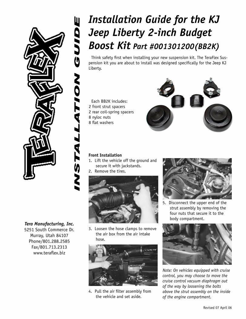
5. Disconnect the upper end of the strut assembly by removing the four nuts that secure it to the body compartment.
Note: On vehicles equipped with cruise control, you may choose to move the cruise control vacuum diaphragm out of the way by loosening the bolts above the strut assembly on the inside of the engine compartment.
Front Installation1. Lift the vehicle off the ground and
secure it with jackstands.2. Remove the tires.
3. Loosen the hose clamps to remove the air box from the air intake hose.
4. Pull the air filter assembly from the vehicle and set aside.
Installation Guide for the KJ Jeep Liberty 2-inch Budget Boost Kit Part #001301200(BB2K)
Each BB2K includes:2 front strut spacers2 rear coil-spring spacers8 nyloc nuts8 flat washers
Think safety first when installing your new suspension kit. The TeraFlex Sus-pension kit you are about to install was designed specifically for the Jeep KJ Liberty.
Tera Manufacturing, Inc.5251 South Commerce Dr.
Murray, Utah 84107Phone/801.288.2585Fax/801.713.2313www.teraflex.biz
IN
STA
LL
AT
IO
N G
UID
E
dbrimley
Text Box
TeraFlex, Inc. 5680 W Dannon Way West Jordan, UT 84081 Phone/801.288.2585 Fax/801.713.2313 www.teraflex.com

Revised 07 April 06
Removing the battery/battery trayNote: Removal of the battery and bat-tery tray allows easier access to the four nuts that secure the upper end of the strut assembly.6. Remove the battery cables starting
with the negative side first and then the positive terminal.
7. Remove the battery. 8. Remove the fuse box to access the
bolts that secure the battery tray.9. With the fuse box out of the way,
you will need to remove the three (3) 13mm bolts that secure the battery tray in position.
Note: Do not disconnect any wiring. Just move the fuse/relay box slightly to the side.
10. Be careful not to break any elec-trical wires that are attached to the battery tray. The connectors that attach the wires to the tray can be easily disconnected.
11. Disconnect the battery sensor from the bottom of the battery tray.
Strut Removal12. You can begin to remove the strut
after the four nuts at the top of the strut assembly have been removed.
13. Use a 21mm wrench to remove the nut that secures the ball joint of the A-arm to the top of the knuckle.
Note: ‘Pickle-fork” style tools can damage the ball joint or boot. Instead, a few simple blows from a hammer will cause the A-arm to separate from the knuckle without damaging the boot.
14. Use a 21mm socket to remove the nut that secures the fork to lower A-arm assembly.
15. Use a 21 mm socket to remove the bolt that secures the top of the fork to the bottom of the strut assembly.
16. Remove the sway bar link at the lower “A” arm.
17. With the bolts removed from the fork, there is enough room to drop the strut from original position. A pry bar is helpful to separate the fork from the bottom of the strut assembly.
18. When the fork is removed, pull the strut assembly from the vehicle.
19. Install the strut spacer on top of the strut using the original flange nuts.
20. Lift the strut assembly into posi-tion. Attach the four top nuts using the new nuts and washers.
Reassemble the fork to the bottom of the strut.
Note:If necessary remove lower A arm bolts to allow more droop.21. Attach the bottom of the fork to
the lower A-arm with the factory bolt. Torque the bolts to factory specifications.
22. A jack stand is a convenient way to raise the knuckle into position so that the upper A-arm can be connected to the knuckle. Torque to factory specifications.
Revised 07 April 06
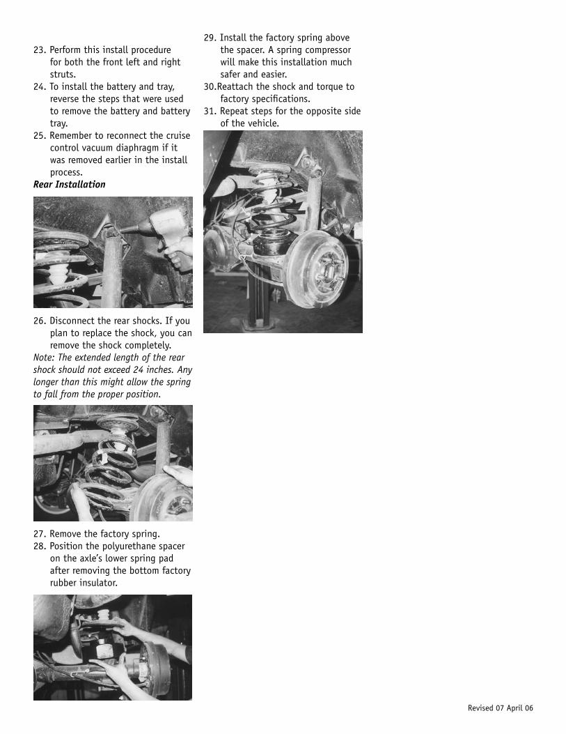
29. Install the factory spring above the spacer. A spring compressor will make this installation much safer and easier.
30.Reattach the shock and torque to factory specifications.
31. Repeat steps for the opposite side of the vehicle.
23. Perform this install procedure for both the front left and right struts.
24. To install the battery and tray, reverse the steps that were used to remove the battery and battery tray.
25. Remember to reconnect the cruise control vacuum diaphragm if it was removed earlier in the install process.
Rear Installation
26. Disconnect the rear shocks. If you plan to replace the shock, you can remove the shock completely.
Note: The extended length of the rear shock should not exceed 24 inches. Any longer than this might allow the spring to fall from the proper position.
27. Remove the factory spring. 28. Position the polyurethane spacer
on the axle’s lower spring pad after removing the bottom factory rubber insulator.

Revised 07 April 06
MAINTENANCE INFORMATION:It is the buyer’s responsibility to have all suspension, drivetrain, steering, and other components checked for proper tightness and torque after the first 100 miles and every 3000 miles after that.
NOTICE TO INSTALLER: The enclosed “Warning to Driver” sticker must be installed in the vehicle in driver’s view. This sticker is to act as a constant safety reminder when operating the vehicle. It is your responsibility as the equipment installer to install the provided sticker and to forward the product instructions to the vehicle’s owner for review. If a “Warning to Driver” sticker or product installation guide were not included in the kit, FREE replacement stickers and instructions are available by request. It is the installer’s duty to ensure a safe and controllable vehicle after the modifications have been performed.
WARNING: Neither the seller nor the manufacturer will be liable for any loss, damage, or injury directly or indirectly arising from the use of or inability to determine the use of these products. Before using, the user shall determine the suitability of the products for its intended use, and the user shall assume all responsibility and risk in connection therewith.
WARNING TO DRIVER: This vehicle has been modified to enhance off road performance and has unique handling characteristics. Use in harsh environments can cause extreme stress on the components. Vehicle should be inspected after being off road to make sure that all the components are in working order and safe to travel on the highway. All fasteners should be checked so that they are at the correct torque specifications as the vibration and stresses from off roading may cause critical fasteners to work loose. Extra care should be taken to inspect the critical components, steering, and brake systems. During each oil change components such as arms, tie rod ends, etc should be greased and checked for excessive wear. Any worn components should be replaced. When returning to the pavement always set or restore tire air pressure to the factory recommendation and connect or engage any disabled sway bar mechanisms. Because of the higher center of gravity and larger tires, this vehicle handles and reacts differently than many passenger cars, both on and off road. You must drive it safely! Extreme care should be taken to prevent vehicle rollover or loss of control, which can result in serious injury or death. Avoid sudden sharp turns or abrupt maneuvers. Generally, braking performance and capabilities are decreased when significantly larger/heavier tires are used, especially when used in combination with transfer case low-range reduction kits. Take this into consideration while driving. Do not add, alter or fabricate any factory or aftermarket parts to increase vehicle height over the intended height of the TeraFlex product purchased. Mixing component brand is not recommended. TeraFlex Inc. will not be responsible for any altered product or any improper installation or use of our products. We will be happy to answer any questions concerning the design, function, and correct use of our products. It is ultimately the buyer’s responsibility to have all bolts/nuts checked for tightness after the first 100 miles and then every 3000 miles. Wheel alignment, steering system, suspension and drive line systems must be inspected by a qualified professional mechanic at least every 3000 miles.
TERAFLEX PRODUCT WARRANTY: Tera Manufacturing warrants TeraFlex Suspension products to the original retail purchaser to be free of defects in material and workmanship for as long as the original purchaser owns the vehicle on which products were originally installed. Failure to complete regular maintenance (grease every 3000 miles) on TeraFlex FlexArms will void this warranty. All other conditions of the standard TeraFlex product warranty apply. All TeraLow products are covered by TeraFlex’s two (2) year warranty to be free of defects in material and workmanship for two years from date purchased. Tera axles are covered by a 12-month warranty to be free of defects in materials and workmanship. This warranty does not cover or include product finish, improperly installed or applied products, improperly maintained products, products or components used for racing or competition or damage due to abuse or neglect, products that fail due to the use of larger tire and wheel combinations. All returns must be accompanied by an original invoice. It is the customer’s responsibility to remove the product from the vehicle. Shipping charges are the responsibility of the customer. Tera Manufacturing will pay the return freight if the product meets the terms of warranty. This warranty is for the replacement or repair of defective TeraFlex products only and does not include freight charges, labor charges for removal of or installation of TeraFlex or related products or components, costs incurred due to down time of the vehicle, or lost profits due to vehicle down time. A returned goods authorization number (RGA#) must accompany any returned products. For more information please contact a TeraFlex customer service representative.
COPYRIGHT©Copyright 2008. All rights reserved, TeraFlex Inc. Reproduction of this catalog and/or any of its contents without written permission is strictly prohibited.TeraFlex® is a registered trademark of TeraFlex Inc. All trade names and logos including but not limited to TeraFlex, FlexArms, RockGuard, Monster, and LCG are protected by law and duplication of trade names and/or logos are strictly prohibited.TeraFlex Inc. reserves the right to update, discontinue, redesign, modify finish, part number or component build parts if deemed necessary without written notice. TeraFlex Inc., and any associated dealers are not responsible for misprints or typographical errors that may have inadvertently been made within this instruction sheet.
Jeep® and the Jeep® grill are registered trademarks of Chrysler LLC, and have no affiliation with TeraFlex Inc.
PRODUCT INFORMATION& WARRANTY
TeraFlex, Inc. 5241 South Commerce Dr. Murray, Utah 84107Phone/801.288.2585 Fax/801.713.2313 www.teraflex.biz