InstallatIon GuIde - fccid.io · MODEL XT30/XT50 XT SERIES™ INSTALLATION GUIDE FCC NOTICE This...
27
INSTALLATION GUIDE XT SERIES™ PANELS
-
Upload
truongthien -
Category
Documents
-
view
216 -
download
0
Transcript of InstallatIon GuIde - fccid.io · MODEL XT30/XT50 XT SERIES™ INSTALLATION GUIDE FCC NOTICE This...

InstallatIon GuIde
Xt serIes™ Panels

MODEL XT30/XT50XT SERIES™
INSTALLATION GUIDE FCC NOTICE
This equipment has been tested and found to comply with the limits for a Class B digital device, pursuant to part 15 of the FCC Rules. These limits are designed to provide reasonable protection against harmful interference in a residential installation. This equipment generates, uses and can radiate radio frequency energy and, if not installed and used in accordance with the instructions, may cause harmful interference to radio communications. However, there is no guarantee that interference will not occur in a particular installation. If this equipment does cause harmful interference to radio or television reception, which can be determined by turning the equipment off and on, the user is encouraged to try to correct the interference by one or more of the following measures:
Reorient or relocate the receiving antenna.•
Increase the separation between the equipment and receiver.•
Connect the equipment into an outlet on a circuit different from that to which the receiver is •connected.
Consult the dealer or an experienced radio/TV technician for help.•
This device has been designed to operate with the antennas listed in the Accesory Devices section, and having a maximum gain of 1.8 dB. Antennas not included in this list or having a gain greater than 1.8 dB are strictly prohibited for use with this device. The required antenna impedance is 50 ohms.
If necessary, the installer should consult the dealer or an experienced radio/television technician foradditionalsuggestions.Theinstallermayfindthefollowingbooklet,preparedbytheFederal
Communications Commission, helpful:
“How to identify and Resolve Radio-TV Interference Problems.”
ThisbookletisavailablefromtheU.S.GovernmentPrintingOffice,WashingtonD.C.20402
StockNo.004-000-00345-4
©2008DigitalMonitoringProducts,Inc.
InformationfurnishedbyDMPisbelievedtobeaccurateandreliable.
This information is subject to change without notice.

XT30/XT50 Installation Guide Digital Monitoring Productsi
table of Contents
Panel Specifications1.1 Power Supply .........................................11.2 Communication .......................................11.3 Panel Zones ............................................11.4 Keypads/Expansion .................................11.5 Number of Zones ....................................11.6 Outputs ..................................................11.7 EnclosureSpecifications ..........................1
Introduction2.1 Description .............................................22.2 SystemConfigurations .............................22.3 BeforeYouBegin ....................................22.4 About this Guide .....................................22.5 NRTL Compliance Instructions .................2
System Components3.1 Description .............................................33.2 WiringDiagram .......................................33.3 LightningProtection ................................33.4 Accessory Devices ...................................33.4 Accessory Devices continued ...................43.5 XT30/XT50WiringDiagram .....................4
Installation4.1 MountingtheEnclosure ...........................54.2 MountingKeypads ..................................54.3 InstallationSpecifications ........................5
Primary Power Supply5.1 AC terminals 1 and 2 ...............................65.2 Transformer Types ..................................6
Secondary Power Supply6.1 Battery Terminals 3 and 4 ........................76.2 Earth Ground ..........................................76.3 Replacement Period ................................76.4 Discharge/Recharge ................................76.5 Battery Supervision .................................76.6 XT30/XT50 Power Requirements ..............76.7 XT30/XT50 Standby Battery Calculations ..8
Bell Output7.1 Terminals 5 and 6 ...................................9
Keypad Data Bus8.1 Description .............................................98.2 Terminal 7 - RED.....................................98.3 Terminal 8 - YELLOW ..............................98.4 Terminal 9 - GREEN.................................98.5 Terminal 10 - BLACK ...............................98.6 ProgrammingConnection ........................98.7 KeypadAddressing ..................................9
Smoke and Glassbreak Detector Output9.1 Terminal 11 ............................................9
Burglary Zones10.1 Description ...........................................1010.2 Operational Parameters .........................1010.3 Zone Response Time .............................1010.4 KeyswitchArmingZone .........................10

Digital Monitoring Products XT30/XT50 Installation Guideii
table of Contents
Powered Zone for 2-Wire Smoke Detectors11.1 Terminals 25 and 26 ..............................11
Annunciator Outputs12.1 Description ...........................................1212.2 HarnessWiring .....................................1212.3 Model 860 Relay Module ........................12
Telephone RJ Connector13.1 Description ...........................................1313.2 FCCRegistration ...................................1313.3 Notification ...........................................13
Ethernet Connector J114.1 Description ...........................................1414.2 Ethernet LEDs ......................................14
Reset Jumpers J1615.1 Description ...........................................14
Flash Load Jumper J1816.1 Description ..........................................14
Cellular Connections17.1 Cellular ...............................................15
On-Board 1100 Series Wireless Antenna Connections18.1 Wireless Antenna .................................15
NRTL Listed Specifications19.1 Introduction .........................................1619.2 Bypass Reports .....................................1619.3 Current Draw ........................................16
Household Burglar-Alarm System Units ANSI/UL 102320.1 Bell Cutoff ............................................1620.2 Entry Delay ..........................................1620.3 Exit Delay .............................................1620.4 Wireless External Contact ......................1620.5 Wireless Supervision Time .....................1620.6 Wireless Audible Annunciation ...............1620.7 Panel location .......................................16
Digital Burglar Alarm Communicator System Units ANSI/UL 163521.1 Entry Delay ..........................................1621.2 Exit Delay .............................................1621.3 Test Frequency .....................................1621.4 Automatic Bell Test ...............................1621.5 Central Station ......................................16
Household Fire Warning System ANSI/UL 985 NFPA 72 Specifications22.1 BellOutputDefinition ............................1722.2 Household System ................................1722.3 HouseholdFireWarning ........................1722.4 Wireless External Contact ......................1722.5 Wireless Supervision Time .....................1722.6 WirelessFireVerification ........................17

XT30/XT50 Installation Guide Digital Monitoring Productsiii
table of Contents
California State Fire Marshal Specifications23.1 BellOutputDefinition ............................17
False Alarm Reduction Programmable Options ANSI/SIA CP-01-200724.1 ShippingDefaultsandProgramming .......1824.2 CallWaiting ..........................................1924.3 Entry Delay ..........................................1924.4 Local Bell .............................................1924.5 Minimum Installation Requirements ........19
Troubleshooting25.1 TroubleshootingSection ........................2025.2 Common LCD Keypad Displays ...............20
Wiring Diagrams26.1 MultipleIndicatingCircuitModules .........21ListingsandApprovals .......................................22

XT30/XT50 Installation Guide Digital Monitoring Products1
Panel sPeCIfICatIons
Panel Specifications1.1 Power Supply
TransformerInput: Plug-in—16.5VAC40VA,Model321 Wire-in—16.5VAC40VA,Model320StandbyBattery: 12VDC7.7Ah(40VAtransformerchargesupto2batteries)AuxiliaryOutput: 12VDCat500mABellOutput: 12VDCat1.5AmpsSmokeDetectorOutput: 12VDCat100mAAll circuits inherent power limitedNote:PleaseseeNRTL(NationalRecognizedTestingLaboratory)ListedSpecificationssectionforaNRTL
certificatedapplication.
1.2 CommunicationBuilt-inSDLCDigitalDialercommunicationtoDMPModelSCS-1RReceiversBuilt-innetworkcommunicationtoDMPModelSCS-1RReceiversBuilt-incellularcommunicationtoDMPModelSCS-1RReceiversBuilt-inCID(ContactID)dialercommunicationtonon-DMPreceivers
1.3 Panel ZonesNine1kOhmEOLburglaryzones:zones1to9One3.3kOhmEOLClassBpoweredfirezonewithresetcapability:zone10
1.4 Keypads/ExpansionYoucanconnectuptofivesupervisedkeypads.
• 32-characteralphanumerickeypadsYoucanconnectunsupervisedkeypads.
• 32-characteralphanumerickeypads• SecurityCommand™, Thinline™, Aqualite™,ClearTouch™,andIconkeypads
Inaddition,thefollowingzoneexpanderscanbeadded:• One,four,eightand16-zoneexpansionmodules• Single-zonePIRandglassbreakdetectors
1.5 Number of ZonesOnboardzones1-10•Fivekeypadbusaddresseswithzones11-14,21-24,31-34,41-44,and51-54(hardwiredorwireless)•Zonenumbers31to34and41to44cansupport1100SeriesKeyFobsorDMPwirelessoutputmodules•XT50has20additionalonboardwirelesszonesnumbered80-99•
1.6 OutputsTheXT30/XT50panelsprovidefouropencollectoroutputsratedfor50mAeach.AModel300OutputHarnessis required. The open collector outputs provide the ground connection for a positive voltage source.
1.7 Enclosure SpecificationsTheXT30/XT50panelshipsstandardina340enclosurewithEOLresistors,batteryleads,user’sguide,andprogrammingsheet.Allenclosuresareconstructedusing20-gaugecoldrolledsteel.
Enclosure Model
Size Color
340 12.5”Wx9.5”Hx2.75”D Gray(G)
349 12.5”Wx11.25”Hx3.5”D Gray(G)

Digital Monitoring Products XT30/XT50 Installation Guide2
IntroduCtIon
Introduction2.1 Description
TheDMPXT30/XT50panelsare12VDCcombinationburglaryandresidentialfirealarmpanelswithbatterybackup.TheXT30andXT50panelsprovidenineon-boardburglaryzonesandoneon-board12VDCClassBpoweredfirezone.Thefirezonehasaresetcapabilitytoprovidefor2-wiresmokedetectors,relays,orotherlatchingdevices.ThepanelscancommunicatetoDMPSCS-1RReceiversusingSDLCdigitaldialer,IPNetwork,orCellularreportingformats.ContactIDreportingisalsoavailabletoCIDcompatiblereceivers.TheXT30has10onboardzonesand5keypadbusaddressesfor20hardwiredorwirelesszonesforatotalof30zones.TheXT50has10onboardzones,5keypadbusaddressesfor20hardwiredorwirelesszones,and20additionalonboardwirelesszonesforatotalof50availablezones.
2.2 System ConfigurationsThe panels can be programmed to operate as either an All/Perimeter system that provides one perimeter areaandoneinteriorarea,orasaHome/Sleep/Awaysystemthatprovidesoneperimeter,oneinterior,andone bedroom area. The bedroom area provides for any protection devices the user wants disarmed during theirsleepinghoursandarmedintheAwaymode.Inaddition,theXT30/XT50canoperateasafourareasystem.
2.3 Before You BeginBeforeinstallingthepanel,werecommendyoureadthroughtheentirecontentsofthisguide.Familiarizeyourselfwiththefeaturesofthepanelandthekeypointstorememberduringtheinstallation.Besuretoread and understand all of the caution statements printed in bold italics. In addition to this installation guide,youshouldalsoreadthroughandfamiliarizeyourselfwiththeseotherproductdocuments:
• XT30/XT50ProgrammingGuide• XT30/XT50User’sGuide
2.4 About this GuideTheinformationcontainedinthisguideisorganizedintofivesections:
• The Table of Contents at the front of this guide lists all of the headings and the page number where the information can be found.
• TheIntroduction section gives you an overview of the various components that go into a panelsystemanddiagramssometypicalsystemconfigurations.
• TheInstallation sectionbeginswithmountinginstructionsfortheenclosureandtakesyouthroughtheproper way to power up the panel prior to programming.
• TheWiring Diagram section provides common system drawings for the panels.Caution notesThroughoutthisguideyouwillseecautionnotescontaininginformationyouneedtoknowwheninstallingthepanel.Thesecautionsareindicatedwithayieldsign.Wheneveryouseeacautionnote,makesureyoucompletely read and understand its information. Failing to follow the caution note can cause damage to the equipmentorimproperoperationofoneormorecomponentsinthesystem.Seetheexampleshownbelow.
Always ground the panel before applying power to any devices: The panel must be properly grounded before connecting any devices or applying power to the panel. Proper grounding protects against ElectrostaticDischarge(ESD)thatcandamagesystemcomponents.
Remove All Power From the Panel! Remove all AC and Battery power from the panel before installing or connecting any modules, cards, or wires to the panel.
2.5 NRTL Compliance InstructionsForapplicationsthatmustconformtoalocalauthoritiesinstallationstandardoraNRTL(NationalRecognizedTestingLaboratory)certificatedsystem,pleaseseetheNRTLListedSpecificationssectionneartheendofthisguide for additional instructions.

XT30/XT50 Installation Guide Digital Monitoring Products3
system ComPonents
System Components
3.1 DescriptionThebasicXTSeriessystemismadeupofanalarmpanelwithbuiltincommunications,anenclosure,a16.5VACtransformer,anda12VDCbattery.Youcanaddkeypadstothesystemandauxiliarydevicestothepanel’sopencollectoroutputstoexpandthesystem.Combinedcurrentrequirementsofadditionalmodulesmayrequireanauxiliarypowersupply.RefertotheStandbyBatteryPowerCalculationsectioninthisguidewhen calculating power requirements.
3.2 Wiring DiagramThe system wiring diagram in Figure 1 on the following page, shows some of the accessory devices you can connect for use in various applications. A description of each module follows.
3.3 Lightning ProtectionMetalOxideVaristorsandTransientVoltageSuppressorshelpprotectagainstvoltagesurgesoninputandoutput circuits. This transient protection provides additional resistance to electrical surges such as lighting. AdditionalsurgeprotectionisavailablebyinstallingtheDMP370or370RJLightningSuppressors.
3.4 Accessory DevicesZone and Output Expansion Modules
710BusSplitter/Repeater Allowsyoutoincreasekeypadwiringdistanceto2500feet.
711SinglePointZoneExpander ProvidesoneClassBzoneforconnectingburglarydevicesandnon-poweredfiredevices.
714,714-8,714-16ZoneExpander ProvidesClassBzonesforconnectingburglaryandnon-poweredfiredevices.
712-8ZoneExpander Provides8zonesforconnectingburglarydevices.
715,715-8,715-16ZoneExpander
Provides12VDCClassBpoweredzonesforconnectingsmokedetectors,glassbreakdetectors,andother2-or4-wiredevices.
860RelayOutputModule Providesthreeadditionalsocketsforexpansionofuptofourrelays.
Interface Card
734WiegandInterfaceCard Provides system codeless entry, and arming and disarming using access control readers.
DMP Two-Way Wireless Devices
1100D/1100DH/1100DIWirelessReceiver
Supportstransmittersinresidentialorcommercialwirelessoperationoffofthekeypadbus.OnlyneededforXT30
1101UniversalTransmitter Provides both internal and external contacts that may be used at the same time to yield two individualreportingzonesfromonewirelesstransmitter.
1102UniversalTransmitter Provides an external contact.
1114Four-ZoneExpander Providesfourwirelesszones
1116RelayOutput Provides one Form C relay
1117LEDAnnunciator Provides a visual system status indicator
1121PIRMotionDetector Provides motion detection with pet immunity.
1125PIRMotionDetector Providesmultiplelensconfigurations,dualcoverageareaselection,andsensitivityadjustments.
1129GlassbreakDetector Detects the shattering of framed glass mounted in an outside wall and provides full-pattern coverage and false-alarm immunity.
1131RecessedContact Provides concealed protection for doors, windows or other applications needing a discreet contact.
1139BillTrap Providesasilentalarmoptionforretailandbankingcashdrawers.
1142BCTwo-buttonPanicBeltClip Transmitter
Provides portable two-button panic operation.
1142Two-buttonPanicTransmitter
Provides permanently mounted under-the-counter two-button panic operation.
1145(Four-Button) 1146(Two-Button) 1147(One-Button)
KeyFobtransmittersdesignedtoclipontoakeyringorlanyard.

Digital Monitoring Products XT30/XT50 Installation Guide4
system ComPonents
3.4 Accessory Devices continued1161ResidentialSmokeDetector Residentialsmokedetectorwithsounder.
1162ResidentialSmokeDetector Residentialsmoke/heatdetectorwithsounderandfixedrate-of-riseheatdetector
Keypads
ePAD™VirtualKeypads Allows users to control the security system from any computer in the world using the Internet.
LCDkeypads Allowsyoutocontrolthepanelfromvariousremotelocations.Connectuptofivekeypads.Model690,790,693/793SecurityCommand™keypads,7060,7063,7070,7073,7160,7163,7170,7173Thinline™keypads,7060A,7063A,7070A,7073AAqualite™keypads,7360,7363Thinline Icon Serieskeypads,or7760ClearTouch™keypadtothekeypadbususingterminals7,8,9,and10.
Cellular Antennas
383RubberduckStubAntenna ProvidesSMARubberduckAntennaforcellularconnection.
384MagneticMountAntenna ProvidesSMAMagneticMountAntennaforcellularconnection.
385DualBandSmartdiscAntenna ProvidesSMADualBandSmartdiscAntennaforcellularconnection.
3.5 XT30/XT50 Wiring Diagram
16 to 18 gauge wire
Maximum AC Wire distance ñ
16 gauge wire: 70 feet18 gauge wire: 40 feet
REDBLACK
Cold Water Pipe Earth Ground
ss
ss
USE MARKINGCommercial Burglary Control Unit (DACT)Household Fire and Burglary Warning System Control Unit.
NFPA 72This equipment should be installed in accordance with Chapter 11 of the National Fire Alarm Code, ANSI/NFPA 72-2002, (National Fire Protection Association, Batterymarch Park, Quincy, MA 02269). Printed information describing proper installation, operation, testing, maintenance, evacuation planning, and repair service is to be provided with this equipment. Warning: Ownerís instruction notice, not to be removed by anyone except occupant.
HOUSEHOLD FIRE WIRINGRecognized limited energy cable must be used for connection of all initiating, indicating, and supplementary devices.
POWER LIMITEDAll circuits on the Model XT30/XT50 comply with the requirements for inherent power limitation and are Class 2.
TYPES OF SERVICESuitable for DACT Central Station. Suitable for Household Fire and Household Burglary. Test weekly.SIA CP-01-2007 minimum system is XT30 or XT50, local Bell, and off premise DACT communication to an SCS-1R receiver plus ANSI/SIA CP-01-2007 classified compatible DMP keypads as indicated in the installation guide.
J3Phone Line
Outputs
J111 2 3 4
J1Ethernet
J16Reset
J20Wireless Antenna
connection
J7 RJ Supervision
J19 Celllular Antenna
connectionXT30/XT50
Command Processorô Panel
RED
PROG
J8Programmer Header J8 Use DMP Model 330 Harness
AC Wiring must be in conduit and exit out the left side of the enclosure.
Wiring on terminals 5 through 26 must exit right and maintain a 1/4" separation from the AC and battery positive wiring.
Terminals 5-20 are Power Limited.
Listed Resistors1.0k Ohm - DMP Model 3113.3k Ohm - DMP Model 309
Plug into 120 VAC 60 Hz outlet not controlled by switch.
Zone 10 compatibility identifier: A
Maximum operating range: 8.8 VDC - 14.2 VDC.
DMP TransformersModel 321 ñ 16.5 VAC 40 VA Class 2 plug-in.Model 320 ñ 16.5 VAC 40 VA Class 2 wire-in.
Verification Zone10
Control Unit Delay
13.6 sec.
Smoke Model
______
DetectorDelay
____sec.
Heat detectors, manual pull stations, or any other shorting device. Unlimited number of units.
1K Ohm EOLon each zone
3.3K Ohm EOLSwitched Voltage Output
Zone 10KeypadBus
Smoke Zones 1 to 9Bell
Secondary Power Supply1.2 Amps maximum charging current. Use only 12 VDC rechargeable batteries. Replace every 3 to 5 years.
Minimum voltage on Auxiliary output to process Sensor trips is 10.4 VDC.
For Wireless Devices, Control Unit delay is 0 (zero).
Bell ó 10.2 - 13.9 VDCTotal current: 1.5 Amps max. w/ 40 VAAUX (RED) ó Up to 500mA auxiliary current at 10.2 - 13.9 VDC from Terminal 7Smoke Output: ó 100mA at 10.2 - 13.9 VDC Terminal 11
Smoke Detector
1k Ohm
ss
To Keypad or Zone
Expander
For NRTL listed applications the maximum current from a combination of bell output, auxillary output, and smoke output is 1.6 amps.
Figure 1: System Wiring Diagram

XT30/XT50 Installation Guide Digital Monitoring Products5
InstallatIon
Installation4.1 Mounting the Enclosure
The metal enclosure must be mounted in a secure, dry place to protect the panel from damage due to tampering or the elements. It is not necessary to remove the PCB when installing the enclosure. The PCB maybeinstalledinthestandard340smallenclosureorintheoptional349mediumenclosure.
Enclosure Mounting Holes
Dual 1/2" and 3/4" Conduit Knockout
Battery Shelf
Enclosure Mounting Holes
J1111
XT30/XT50
Phone JackConnector
Command ProcessorReset
J16
J4
J111234
Slide panel PCB into lower enclosure slots
Panel PCB
screw
Panel PCB
screw
Model 349 Enclosure
Slide panel PCB between formed metal supports
Dual 1/2" and 3/4" Conduit Knockouts
Battery Shelf
Enclosure Mounting Holes
Enclosure Mounting
Hole
Enclosure Mounting
Hole Phone Jack Connector
J4
Command Processor Reset
J16
J11
1234
XT30/XT50 Panel PCB
screw
Panel PCB
screw
Model 340 Enclosure
Figure 2: Standard 340 Enclosure (left) or Optional 349 Enclosure (right)
4.2 Mounting KeypadsDMPkeypadshaveremovablecoversthatallowthebasetobemountedonawallorotherflatsurfaceusingthe screw holes provided on each corner.
Formountingkeypadsonsolidwalls,orforapplicationswhereconduitisrequired,useaDMP695or696keypadconduitbackbox.
4.3 Installation SpecificationsSeveralfactorsdeterminetheperformancecharacteristicsofthekeypadbus:thelengthofwireused,thenumberofdevicesconnected,andthevoltageateachdevice.Whenplanningakeypadbusinstallation,keepinmindthefollowingfourspecifications:
1.DMPrecommendsusing18or22-gaugeunshielded wireforallkeypadcircuits.Do not use twisted pair orshieldedwireforkeypadbusdatacircuits.
2.Onkeypadbuscircuits,tomaintainauxiliarypowerintegritywhenusing22-gaugewiredonotexceed500feet.Whenusing18-gaugewiredonotexceed1,000feet.Toincreasethewirelengthortoadddevices, install an additional power supply. Note:Eachpanelallowsaspecificnumberofsupervisedkeypads.Addadditionalkeypadsintheunsupervisedmode.Refertothepanelinstallationguideforthespecificnumberofsupervisedkeypadsallowed.
3.Maximumdistanceforanyonebuscircuit(lengthofwire)is2,500feetregardlessofthewiregauge.This distance can be in the form of one long wire run or multiple branches with all wiring totaling no morethan2,500feet.Aswiredistancefromthepanelincreases,DCvoltageonthewiredecreases.
4.Maximumvoltagedropbetweenthepanel(orauxiliarypowersupply)andanydeviceis2.0VDC.Ifthevoltage at any device is less than the required level, add an auxiliary power supply at the end of the circuit.Whenvoltageistoolow,thedevicescannotoperateproperly.
Foradditionalinformationrefertothe710InstallationSheet(LT-0310)andortheLX-Bus/KeypadBusWiringApplicationNote(LT-2031).
Digital Monitoring Products XT30/XT50 Installation Guide6
InstallatIon
Primary Power Supply
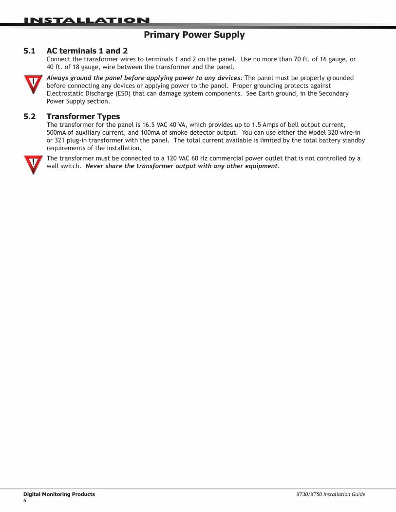
5.1 AC terminals 1 and 2Connectthetransformerwirestoterminals1and2onthepanel.Usenomorethan70ft.of16gauge,or 40ft.of18gauge,wirebetweenthetransformerandthepanel.
Always ground the panel before applying power to any devices: The panel must be properly grounded before connecting any devices or applying power to the panel. Proper grounding protects against ElectrostaticDischarge(ESD)thatcandamagesystemcomponents.SeeEarthground,intheSecondaryPowerSupplysection.
5.2 Transformer TypesThetransformerforthepanelis16.5VAC40VA,whichprovidesupto1.5Ampsofbelloutputcurrent,500mAofauxiliarycurrent,and100mAofsmokedetectoroutput.YoucanuseeithertheModel320wire-inor321plug-intransformerwiththepanel.Thetotalcurrentavailableislimitedbythetotalbatterystandbyrequirements of the installation.
Thetransformermustbeconnectedtoa120VAC60Hzcommercialpoweroutletthatisnotcontrolledbyawall switch. Never share the transformer output with any other equipment.

XT30/XT50 Installation Guide Digital Monitoring Products7
InstallatIon
Secondary Power Supply
6.1 Battery Terminals 3 and 4Connecttheblackbatteryleadtothenegativebatteryterminal.ThenegativeterminalconnectstotheenclosuregroundinternallythroughtheXT30orXT50circuitboard.Connecttheredbatteryleadtothepositivebatteryterminal.Observepolaritywhenconnectingthebattery.
Add a second battery in parallel usingtheDMPModel318DualBatteryHarness. DMP requires each battery be separated by a PTC in the battery harness wiring to protect each battery from a reversal or short within the circuit. See Figure 4.
Use sealed lead-acid batteries only: Use12VDCsealedlead-acidrechargeable battery. Batteries suppliedbyDMPhavebeentestedtoensureproperchargingwithDMPproducts.
GEL CELL BATTERIES CANNOT BE USED WITH THE XT30/XT50 PANEL.
6.2 Earth GroundTerminal4ofthepanelmustbeconnectedtoearthgroundusing14gaugeorlargerwiretoprovidepropertransientsuppression.DMPrecommendsconnectingtoametalcoldwaterpipeorgroundrodonly.Donotconnect to electrical conduit or a telephone company ground.
6.3 Replacement PeriodDMPrecommendsreplacingthebatteryevery3to5yearsundernormaluse.
6.4 Discharge/RechargeThepanelbatterychargingcircuitfloatchargesat13.9VDCatamaximumcurrentof1.2Ampsusinga40VAtransformer. The total current available is reduced by the combined auxiliary current draw from terminals 7,11,and25.Thevariousbatteryvoltagelevelsarelistedbelow:
BatteryTrouble: Below 11.9VDCBatteryRestored: Above 12.6VDC
6.5 Battery SupervisionThe panel tests the battery once every hour when AC power is present. This test occurs 15 minutes past eachhourandlastsforfiveseconds.Aloadisplacedonthebatteryandifitsvoltagefallsbelow11.9VDCalow battery is detected. If AC power has failed, a low battery is detected any time the battery voltage falls below11.9VDC.
If a low battery is detected with AC power present, the test is repeated every two minutes until the battery chargesabove12.6VDC;thebatteryrestoredvoltage.Ifafaultybatteryisreplacedwithafullychargedbattery, the restored battery will not be detected until the next two-minute test is done.
6.6 XT30/XT50 Power RequirementsDuring AC power failure, the panel and all auxiliary devices connected draw their power from the battery. Alldevicesmustbetakenintoconsiderationwhencalculatingthebatterystandbycapacity.Onthefollowingpageisalistofthepowerrequirementsofthepanel.AddtheadditionalcurrentdrawofDMPkeypads,smokedetectoroutput,andanyotherauxiliarydevicesusedinthesystemforthetotalcurrentrequired. The total is then multiplied by the total number of standby hours required to arrive at the total Ampere-hours required.
AC
1 2 3 4
+BAC –B
318 Battery Harness
Panel Red and Black Battery Cables
Red
Black
BatteryBattery
Red
Black
5 6
BELL GND
To AC
14 AWG toEarth Ground
XT30/XT50Command Processor
Panel
PTCTo BellCircuit
Figure 4: Wiring Multiple Batteries

Digital Monitoring Products XT30/XT50 Installation Guide8
InstallatIon
6.7 XT30/XT50 Standby Battery Calculations
Standby Battery Power Calculations Alarm CurrentXT30 PanelXT50 Panel Built-in Network (additional current) Built-in Cellular (additional current)
Active Zones 1-9 Active Zone 10 2-Wire Smoke Detectors Panel Bell Output
xxxxxx
125mA145mA145mA17mA1.6mA
4mA0.1mA
______mA____________________________________
Qty ______Qty ______Qty ______
1500mA
xxxx
125mA145mA145mA65mA*2mA30mA0.1mA
Max.
______mA__________________________________________
263GDigitalCellularCommunicator x 17mA ______ Qty ______ x 65mA ______
1100D Wireless Receiver x 40mA ______ Qty ______ x 40mA ______
1100DHWirelessHighPowerReceiver x 160mA ______ Qty ______ 160mA ______
1100DI Wireless In-Line Receiver x 30mA ______ Qty ______ 30mA ______690 Security Command Keypad x 77mA ______ Qty ______ x 84mA ______693 Security Command Keypad x 92mA ______ Qty ______ x 120mA ______790 Security Command Keypad
Active Zones (EOL Installed)x 77mA
1.6mA____________
Qty ______Qty ______
xx
84mA*2mA
____________
793 Security Command Keypad Active Zones (EOL Installed)
x 92mA1.6mA
____________
Qty ______Qty ______
xx
120mA*2mA
____________
7060/7160 Thinline/7060A Aqualite Keypad x 72mA ______ Qty ______ x 87mA ______7063/7163 Thinline/7063A Aqualite Keypad x 85mA ______ Qty ______ x 100mA ______7360 Thinline Icon Keypad7363 Thinline Icon Keypad7070/7170 Thinline/7070A Aqualite Keypad
Active Zones (EOL Installed)
xxx
60mA73mA72mA1.6mA
________________________
Qty ______Qty ______Qty ______Qty ______
xxxx
67mA80mA87mA*2mA
________________________
7073/7173 Thinline/7073A Aqualite Keypad Active Zones (EOL Installed)
x 85mA1.6mA
____________
Qty ______Qty ______
xx
100mA*2mA
____________
734WiegandInterfaceModule Active Zones (EOL Installed)
xx
15mA1.6mA
____________
Qty ______Qty ______
xx
15mA*2mA
____________
738A Ademco Wireless Interface Module x 75mA ______ Qty ______ x 75mA ______708 Bus Extender Module (one pair) x 20mA ______ Qty ______ x 20mA ______710 Bus Splitter/Repeater Module x 30mA ______ Qty ______ x 30mA ______714 Zone Expansion Modules
Active Zones (EOL Installed)xx
7mA1.6mA
____________
Qty ______Qty ______
xx
7mA*2mA
____________
712-8 Zone Expansion Module Active Zones (EOL Installed)
xx
17mA1.6mA
____________
Qty ______Qty ______
xx
17mA*2mA
____________
714-8, 714-16 Zone Expansion Module Active Zones (EOL Installed)
xx
20mA1.6mA
____________
Qty ______Qty ______
xx
20mA*2mA
____________
715 Zone Expansion Module Active Zones (EOL Installed) 2-Wire Smokes
xxx
7mA4mA.1mA
__________________
Qty ______Qty ______Qty ______
xxx
7mA*30mA
.1mA
__________________
715-8, 715-16 Zone Expansion Modules Active Zones (EOL Installed) 2-Wire Smokes
x 20mA4mA.1mA
__________________
Qty ______ x 20mA*30mA
.1mA
__________________
Aux. Powered Devices on Terminals 7 and 11 Other than Keypads and Modules
______mA ______mA
Total Standby
Total Standby______mA x number of Standby Hours
needed
Total Alarm
* Based on 10% of active zones in alarm condition.
______mA
______ =
______mA
+
Total
Total Alarm
________mA-hours
________mA-hours
________mA-hours
X .001
= ________Amp-hrs
______mA
Required

XT30/XT50 Installation Guide Digital Monitoring Products9
InstallatIon
Bell Output
7.1 Terminals 5 and 6Nominal12VDCissuppliedbyterminal5onthepaneltopoweralarmbellsorhorns.Theoutputisratedforamaximumof1.5Ampswitha40VAtransformer.Thisoutputcanbesteady,pulsed,orTemporalCode3dependingupontheBellActionspecifiedinOutputOptionsprogramming.Terminal6isthegroundreferenceforthebellcircuit.Ifusingahornorsiren,a1k0hm1/2Wresistershouldbeaddedacrossthebellcircuitfor supervision.
Keypad Data Bus
8.1 DescriptionTerminals7,8,9,and10ofthepanelaredesignatedasthekeypaddatabus.Inadditiontokeypads,theXT30/XT50allowstheconnectionofanycombinationofzoneexpansionmodules,5845LXGlassbreakDetectors,and6155LXPIRstothekeypadbusuptothemaximumoffivedevices.
8.2 Terminal 7 - REDNominal12VDCissuppliedatterminal7topowerkeypadsandzoneexpanders.Thisisalsowherepowerforanyauxiliarydeviceissupplied.Thegroundreferenceforterminal7isterminal10.Themaximumoutputisratedat500mA.AllauxiliarydevicestotaledtogethermustnotexceedtheTerminal7maximumcurrent rating of 500mA.
8.3 Terminal 8 - YELLOWDatareceivefromkeypadsandzoneexpanders.
8.4 Terminal 9 - GREENDatatransmittokeypadsandzoneexpanders.
8.5 Terminal 10 - BLACKTerminal10isthegroundreferenceforLCDkeypads,zoneexpanders,andanyauxiliarydevicesbeingpoweredbyterminals7and11.
8.6 Programming ConnectionAlocking4-pinheader(J8)isprovidedtoconnectakeypadwhenusingaDMPModel330ProgrammingCable.Thisprovidesaquickandeasyconnectionforprogrammingthepanel.
8.7 Keypad AddressingKeypadBusexpansionzonesarenumberedingroupsoffourcorrespondingtotheaddress.Example:address1iszones11-14andaddress5iszones51-54.Thereareamaximumof20zonespossibleontheKeypadBus.Allkeypadzonesterminatewitha1k0hmEOLresister.
Address XT30/XT50 Zone Number
1 11-142 21-243 31-344 41-445 51-54
8.8 OVC LEDTheOvercurrentLED(OVC)lightsRedwhenthedevicesconnectedtotheKeypadBusandLX-Bus(es)drawmorecurrentthanthepanelisratedfor.TheOVCislocatedaboveOutputs1and2onthepanelandturnsasteadyRedwhenlit.WhentheOVCLEDlightsRed,theLX-Bus(es)andKeypadbusareshutdown.
Smoke and Glassbreak Detector Output
9.1 Terminal 11Nominal12VDCat100mAmaximum(sharedbyterminal25)issuppliedatterminal11topower4-wiresmokedetectorsorotherauxiliarypowereddevices.Thisoutputcanbeturnedoffbytheuserfor5secondsusingtheSensorResetoptionintheUserMenu.Terminal10isthegroundreferenceforterminal11.

Digital Monitoring Products XT30/XT50 Installation Guide10
InstallatIon
Burglary Zones
10.1 DescriptionOnXT30/XT50panels,terminals12to24arethenineburglaryzones.Forprogrammingpurposes,thezonenumbersare1to9.Thezoneconfigurationsonterminals12to24aredescribedbelow.
Terminal Function Terminal Function 12 Zone1voltagesensing 19 Groundforzones5&6 13 Groundforzones1&2 20 Zone6voltagesensing 14 Zone2voltagesensing 21 Zone7voltagesensing 15 Zone3voltagesensing 22 Groundforzones7,8,&9 16 Groundforzones3&4 23 Zone8voltagesensing 17 Zone4voltagesensing 24 Zone9voltagesensing 18 Zone 5 voltage sensingThevoltagesensingterminalmeasuresthevoltageacrossthe1kOhmEnd-of-Lineresistorandthezone’sgroundterminal.Drycontactsensingdevicescanbeusedinseries(normally-closed)orinparallel(normally-open)withanyoftheburglaryprotectionzones.
10.2 Operational ParametersEachburglaryprotectionzonedetectsthreeconditions:open,normal,andshort.
The parameters for each are listed below:
Condition Resistance on zone Voltage on zone terminal Open over1300ohms over2.0VDC Normal 600to1300ohms 1.2to2.0VDC Short under600ohms under1.2VDC
1K OhmNormallyClosed
1K OhmNormally Open
1K OhmCombination Normally Open
and Normally Closed
Figure 5: Protection Zone Contact Wiring
10.3 Zone Response TimeAconditionmustbepresentonazonefor500millisecondsbeforeitisdetectedbythepanel.Ensuredetectiondevicesusedontheprotectionzonesareratedforusewiththisdelay.
10.4 Keyswitch Arming ZoneYoucanuseamomentarykeyswitchonazoneprogrammedasanArmingtypeforuseinarminganddisarming the system without a code.

XT30/XT50 Installation Guide Digital Monitoring Products11
InstallatIon
Powered Zone for 2-Wire Smoke Detectors
11.1 Terminals 25 and 26Aresettable2-wireClassBpoweredzoneisprovidedonterminals25(positive)and26(negative)ofthepanel.Forprogrammingpurposes,thezonenumberis10ontheXT30/XT50.ThezoneusesaModel309,3.3kOhmEOLresistor(providedwiththepanel)andhasanoperatingrangeof8.8to13.9VDC.
Thecompatibilityidentifieris:A.
Caution:Sensorresetonzone10willdroppowertodevicesonthiszone,causingthepaneltosenseanopenconditiononallzonetypesotherthanFire,FireVerify,andSupervisory.Whenevernon-Fireandnon-Supervisoryzonetypesareusedonzone10,maketheappropriateadjustmentstothezone’sArmedActionto prevent false alarms from occurring.
Manufacturer Model Detector ID Base Base
ID# of
Detectors
Zone Expansion Modules
Detection Systems DS250, DS250TH B MB2W, MB2WL A 10 715, 715-8, 715-16, 725
Detection Systems DS250HD B MB2W, MB2WL A 10 715, 715-8, 715-16
Detection Systems DS282, DS282TH B 10 715, 715-8, 715-16, 725
DMP/Hochiki SLK-835 HD-5 HSB-200, HSB-200N HB-55 7 715, 715-8,
715-16
DMP/Hochiki SLR-835 HD-3 NS6-100 HB-55 7 715, 715-8, 715-16, 725
DMP/Hochiki SLR-835B HD-6 7 715, 715-8, 715-16, 725
Sentrol/ESL 429AT, 521B, 521BXT S09A 12 715, 715-8, 715-16

Digital Monitoring Products XT30/XT50 Installation Guide12
InstallatIon
Annunciator Outputs
12.1 DescriptionThefourannunciatoroutputscanbeprogrammedtoindicatetheactivityofthepanel’szonesorconditionsoccurring on the system. Annunciator outputs do not provide a voltage but instead switch-to-ground voltage from another source. The outputs can respond to any of the conditions listed below:
1) Activationbyzonecondition:Steady,Pulse,Momentary,orFollower 6) Ambushalarm2) Manuallyfromthekeypad 7) ExitandEntrytimers3) Communicationfailure 8) SystemReady4) Armedareaannunciation 9) LatetoClose5) FireAlarmorFireTrouble
12.2 Harness WiringTheopencollectoroutputsareaccessiblebyinstallingtheDMP300Harnessonthe4-pinheaderlabeledJ11.The output locations are shown below.
Output Color Wire Output Color Wire 1 Red 1 3 Green 3 2 Yellow 2 4 Black 4
12.3 Model 860 Relay ModuleConnectaModel860RelayModuletothepaneltoproviderelaysfortheannunciatoroutputsthatcanbeused for electrical isolation between the alarm panel and other systems or for switching voltage to control variousfunctions.Themoduleincludesonerelayandprovidesthreeadditionalsocketsforexpansionofuptofourrelays.Powerissuppliedtotherelaycoilsfromthepanelkeypadbus.The860mountsinsidethepanelenclosureusingthe3-holemountingconfiguration.Plasticstandoffsareprovidedwiththemoduleforeaseofinstallation.A4-wireharnessisalsoprovidedthatconnectstheModel860tothepanel.
Relay Contact Rating: 1Ampat30VDC
XT30/XT50 Installation Guide Digital Monitoring Products13
InstallatIon
Telephone RJ Connector
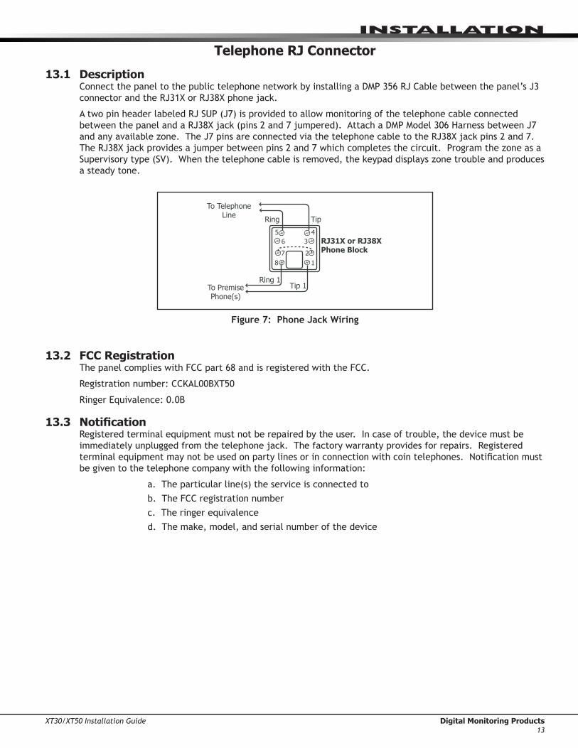
13.1 DescriptionConnectthepaneltothepublictelephonenetworkbyinstallingaDMP356RJCablebetweenthepanel’sJ3connectorandtheRJ31XorRJ38Xphonejack.
AtwopinheaderlabeledRJSUP(J7)isprovidedtoallowmonitoringofthetelephonecableconnectedbetweenthepanelandaRJ38Xjack(pins2and7jumpered).AttachaDMPModel306HarnessbetweenJ7andanyavailablezone.TheJ7pinsareconnectedviathetelephonecabletotheRJ38Xjackpins2and7.TheRJ38Xjackprovidesajumperbetweenpins2and7whichcompletesthecircuit.ProgramthezoneasaSupervisorytype(SV).Whenthetelephonecableisremoved,thekeypaddisplayszonetroubleandproducesa steady tone.
To Telephone Line
RJ31X or RJ38X Phone Block
87
65 4
3
21
Ring Tip
To Premise Phone(s)
Ring1Tip 1
Figure 7: Phone Jack Wiring
13.2 FCC RegistrationThe panel complies with FCC part 68 and is registered with the FCC.
Registrationnumber:CCKAL00BXT50
RingerEquivalence:0.0B
13.3 NotificationRegistered terminal equipment must not be repaired by the user. In case of trouble, the device must be immediatelyunpluggedfromthetelephonejack.Thefactorywarrantyprovidesforrepairs.Registeredterminalequipmentmaynotbeusedonpartylinesorinconnectionwithcointelephones.Notificationmustbe given to the telephone company with the following information:
a.Theparticularline(s)theserviceisconnectedto b. The FCC registration number c. The ringer equivalence d.Themake,model,andserialnumberofthedevice
Digital Monitoring Products XT30/XT50 Installation Guide14
InstallatIon
Ethernet Connector J1
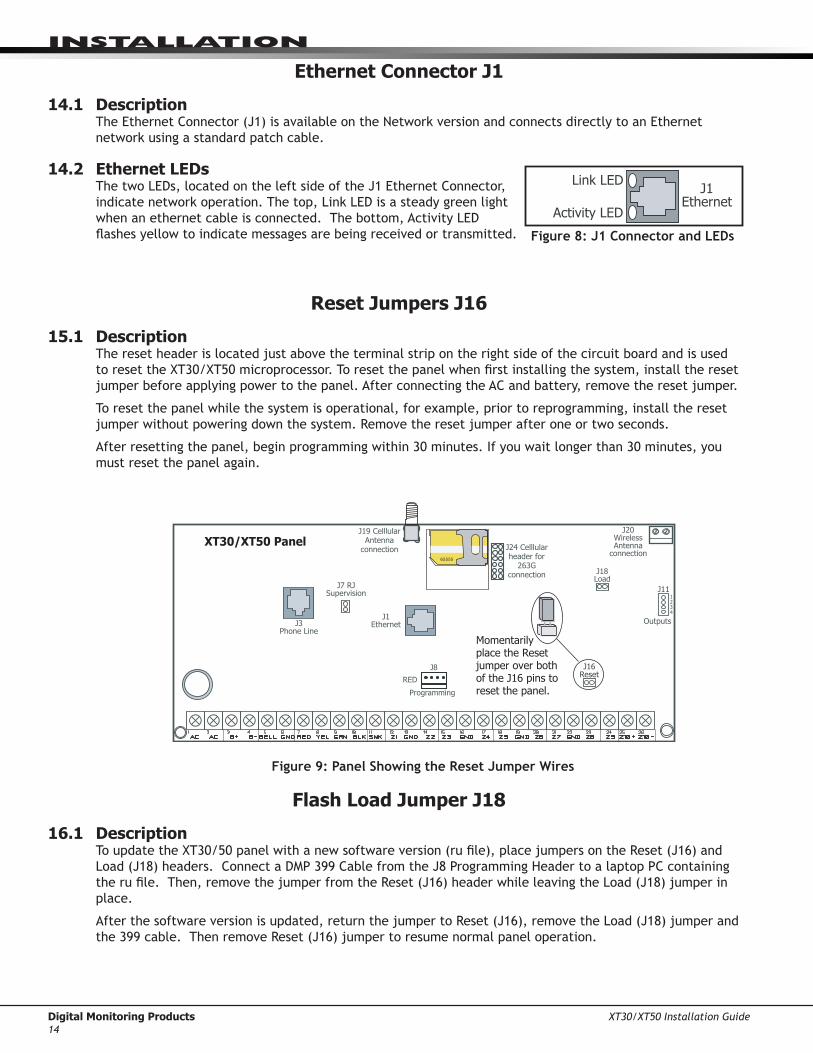
14.1 DescriptionTheEthernetConnector(J1)isavailableontheNetworkversionandconnectsdirectlytoanEthernetnetworkusingastandardpatchcable.
14.2 Ethernet LEDsThetwoLEDs,locatedontheleftsideoftheJ1EthernetConnector,indicatenetworkoperation.Thetop,LinkLEDisasteadygreenlightwhenanethernetcableisconnected.Thebottom,ActivityLEDflashesyellowtoindicatemessagesarebeingreceivedortransmitted.
Reset Jumpers J16
15.1 DescriptionThe reset header is located just above the terminal strip on the right side of the circuit board and is used toresettheXT30/XT50microprocessor.Toresetthepanelwhenfirstinstallingthesystem,installtheresetjumper before applying power to the panel. After connecting the AC and battery, remove the reset jumper.
To reset the panel while the system is operational, for example, prior to reprogramming, install the reset jumper without powering down the system. Remove the reset jumper after one or two seconds.
Afterresettingthepanel,beginprogrammingwithin30minutes.Ifyouwaitlongerthan30minutes,youmust reset the panel again.
XT30/XT50 Panel
J3Phone Line
Outputs
J111 2 3 4J1
Ethernet
J20Wireless Antenna
connection
J7 RJ Supervision
J24 Celllular header for
263G connection
J19 Celllular Antenna
connection65555
Momentarily place the Reset jumper over both of the J16 pins to reset the panel.
J16Reset
J18Load
REDProgramming
J8
Figure 9: Panel Showing the Reset Jumper Wires
Flash Load Jumper J18
16.1 Description ToupdatetheXT30/50panelwithanewsoftwareversion(rufile),placejumpersontheReset(J16)andLoad(J18)headers.ConnectaDMP399CablefromtheJ8ProgrammingHeadertoalaptopPCcontainingtherufile.Then,removethejumperfromtheReset(J16)headerwhileleavingtheLoad(J18)jumperinplace.
Afterthesoftwareversionisupdated,returnthejumpertoReset(J16),removetheLoad(J18)jumperandthe399cable.ThenremoveReset(J16)jumpertoresumenormalpaneloperation.
Figure 8: J1 Connector and LEDs
J1Ethernet
Link LED
Activity LED

XT30/XT50 Installation Guide Digital Monitoring Products15
InstallatIon
Cellular Connections
17.1 Cellular TheXT30/XT50Cellularoptionisavailablebuilt-inatthefactoryorasanoptionaladd-onmodule,Model263G.TheJ19SMAcellularantennaconnectorisprovidedforthebuilt-incellularversionandprotrudesthrough the top of the enclosure.
Ifthepanelisnotpurchasedwithbuilt-incellular,thentheJ24headerisprovidedtoconnecta263GDigitalCellularCommunicatorasanadd-on.The263GDigitalCellularCommunicatorprovidesacellularantennaconnectionthatprotrudesthroughthetopoftheenclosuresimilartoJ19.
Figure 10: Cellular and 1100 Series Wireless Antenna Connections
On-Board 1100 Series Wireless Antenna Connections
18.1 Wireless Antenna TheXT50WirelessAntennaterminalblockJ20islocatedatthetoprightcornerofthecircuitboard.Theantenna installs through a small opening in the top of the enclosure and is attached to the panel using the right terminal. The left terminal is not used.
TheXT50built-inwirelessoperateswithDMP1100Seriestransmitters.Seesection3.4foralistofaccessorydevices.
18.2 LED OperationTwoLEDsdisplayreceiveroperationandactivity.Refertothetablebelowasrequired.
OperationGreenLED-Flashestoindicatedataisbeingtransmittedfromthereceiver.YellowLED-Flashestoindicatedataisbeingreceivedfromatransmitter.
Outputs
J111 2 3 4
J1Ethernet
J16Reset
J201100 Series
Wireless Antenna
connection
J24 Celllular header for
263G connection
J19 Celllular Antenna
connector65555
Built-in Cellular Module Connect
antenna to rightside
only
J18Load
RED
Programming
J8
1100 SeriesAntenna(XT50)
Model 383supplied
with panel
Digital Monitoring Products XT30/XT50 Installation Guide16
ComPlIanCe
NRTL Listed Specifications
19.1 IntroductionTheprogrammingandinstallationspecificationscontainedinthissectionmustbecompletedwheninstallingtheXT30/XT50inaccordancewithanyoftheANSI/ULburglarystandards.Additionalspecificationsmayberequired by a particular standard.
19.2 Bypass ReportsThebypassreportsmustbeprogrammedasYESforallNRTL(NationalRecognizedTestingLaboratory)Listedburglary applications.
19.3 Current DrawThetotalcurrentdrawfromacombinationofauxiliary,smoke,andbelloutputterminalsmustnotexceed1.6 Amps.
Household Burglar-Alarm System Units ANSI/UL 102320.1 Bell Cutoff
The bell cutoff time cannot be less than four minutes.
20.2 Entry DelayThemaximumentrydelayusedmustnotbemorethan45seconds.
20.3 Exit DelayThe maximum exit delay used must not be more than 60 seconds.
20.4 Wireless External ContactWhenused,theExternalContactof1101or1102mustbeprogrammedNormallyClosed.
20.5 Wireless Supervision TimeTheZoneInformationSupervisionTimecannotbesetto0(zero).
20.6 Wireless Audible AnnunciationTheWirelessAudibleoptionmustbeselectedasDAYforresidentialapplications.
20.7 Panel locationMountpanelinsideprotectedareaorhavetamperswitchinstalledonenclosure.Zone1maybeprogrammedfor Alarm on Tamper.
Digital Burglar Alarm Communicator System Units ANSI/UL 163521.1 Entry Delay
The maximum entry delay used must not be more than 60 seconds.
21.2 Exit DelayThe maximum exit delay used must not be more than 60 seconds.
21.3 Test FrequencyTheTestFrequencyoptionmustbeprogrammedtosendareportonceevery24hours.
21.4 Automatic Bell TestThisoptionmustbeprogrammedasYES.
21.5 Central StationDigitalDialerCentralStation(DACT)serviceforcommercialapplicationcanbeprovidedunderUL1635byaddingalistedlocalaudiblesignalapplianceandplacingtheXT30orXT50panelintotheModel350AAttackResistantEnclosure.

XT30/XT50 Installation Guide Digital Monitoring Products17
ComPlIanCe
Household Fire Warning System ANSI/UL 985 NFPA 72 Specifications
22.1 Bell Output DefinitionThebelloutputoftheModelXT30/XT50mustbeprogrammedtooperatesteadyonburglaryalarmsandpulsedonfirealarms.SeetheXT30/XT50ProgrammingGuide.
22.2 Household SystemAn alarm sounding device must be installed indoors so that it is clearly heard in all sleeping areas.
22.3 Household Fire WarningRecognizedlimitedenergycablemustbeusedforconnectionofallinitiating,indicating,andsupplementarydevices.
22.4 Wireless External ContactWhenused,theExternalContactof1101or1102mustbeprogrammedNormallyClosed.SeetheXT30/XT50ProgrammingGuide.
22.5 Wireless Supervision TimeTheZoneInformationSupervisionTimemustbe3minutesforfiredevices.SeetheXT30/XT50ProgrammingGuide.
22.6 Wireless Fire VerificationWhenused,theModel1161and1162wirelesssmokedetectorsmustnotbeprogrammedasFireVerification(FV)zonetype.SeetheXT30/XT50ProgrammingGuide.
California State Fire Marshal Specifications23.1 Bell Output Definition
ThebelloutputoftheModelXT30/XT50mustbeprogrammedtooperatesteadyonburglaryalarmsandtemporalonfirealarms.

Digital Monitoring Products XT30/XT50 Installation Guide18
ComPlIanCe
False Alarm Reduction Programmable Options ANSI/SIA CP-01-2007
24.1 Shipping Defaults and Recommended Programming
SIA CP-01 FEATURE PARAGRAPH # AND
DESCRIPTION
DMP PROGRAMMING GUIDE LT-0981
SECTION #REQUIREMENT RANGE SHIPPING
DEFAULTRECOMMENDED PROGRAMMING*
4.2.2.1ExitTime 8.6ExitDelay Required (Programmable) 45sec.-250sec. 60
Seconds 60Seconds
4.2.2.2ProgressAnnunciation
13.14PrewarnAddress Allowed
Individualkeypadsmay be disabled per zone
All keypadsenabled
Allkeypadsenabled
4.2.2.3ExitTimeRestart 8.6ExitDelay RequiredOption For re-entry during
exit time Enabled Enabled
4.2.2.5AutoStayArmonUnvacatedPremises
8.17OccupiedPremise - SeeInstallGuide
RequiredOption(exceptforremotearming)
OccupiedPremiseNO/YESoption Enabled
EnabledYesfor Residential Applications
4.2.4.4ExitTimeandProgress Annunciation/Disable - for Remote Arm
NotAvailableonRemote Arming AllowedOption
Progress Annunciation Always disabled for Remote Arming
NotAvailable
Remote Arming not allowed for CP-01 installations.
4.2.3.1EntryDelay(s) 8.5EntryDelay Required (Programmable) 30sec.–240Sec.** 30
Seconds Atleast30Seconds**
4.2.5.1AbortWindow–forNon-FireZones 3.3TransmitDelay RequiredOption Disablebyzoneor
zonetype
EnabledNTDYEXZone
Enabled
4.2.5.1AbortWindowTime–forNon-FireZones
3.3TransmitDelay Required (Programmable)
20sec.,30sec.,or40sec.**
30Seconds Atleast20Seconds**
4.2.5.1.2AbortAnnunciation 3.3TransmitDelay RequiredOption
Annunciate that no alarm was transmitted
Yes Yes
4.2.5.4.1CancelAnnunciation
AlwaysEnabled-NotProgrammable RequiredOption
Annunciate that a Cancel was transmitted(S49)
Always Enabled Yes
4.2.6.1&4.2.6.2Duress Feature
UserCode+1=AmbushCodeNotAvailable
AllowedOption
No1+derivativeofanother user code/no duplicates with other user codes
Code+1Always Disabled
NotProgrammable
4.3.1CrossZoning 13.16CrossZone RequiredOption Yes/NoZoneProgramming No
Enabledusingtwoormore programmed zones
4.3.1ProgrammableCross Zoning Time 8.7CrossZoneTime Allowed 4sec.-250sec. 0Seconds Perwalkpathin
protected premises
4.3.2SwingerShutdown NotAvailable—AlwaysOn Required
Forallnon-firezones,shutdownafter 1 trip
Always On AlwaysOn
4.3.2SwingerShutdownDisable 13.13SwingerBypass Allowed For non-police
responsezones Yes Enabled(allzones)
4.3.3FireAlarmVerification 13.5ZoneType RequiredOption FV Type Zone No
Yes as required (unlesssensorscanselfverify)
4.5CallWaitingCancel 3.17FirstTelephoneNumber RequiredOption Include*70Pin
TelephoneNumber Disabled Enabledifuserhascall waiting
*ProgrammingatinstallationmaybesubordinatetootherNRTLrequirementsfortheintendedapplication. **ForNRTLInstallations,combinedEntryDelayandTransmitDelayshouldnotexceed1minute.

XT30/XT50 Installation Guide Digital Monitoring Products19
ComPlIanCe
False Alarm Reduction Programmable Options ANSI/SIA CP-01-2007 (continued)
24.2 Call WaitingTheCallWaitingdefaultsettingisdisabled.TocanceltheCallWaitingfeature,program*(star)70P(pause),thestandardtelephonecodeprefixthatcancelscallwaiting,intothetelephonenumberstring.CancelCallWaitingfortelephonelinesthathaveCallWaitingoperationalonthetelephoneline.SeetheXT30/XT50ProgrammingGuide.
Caution: A call waiting cancel programmed on a non-call waiting telephone line, would prevent communication to the central station.
24.3 Entry DelayOnlyuseEntryDelay1.DonotuseEntryDelay2.SeetheXT30/XT50ProgrammingGuide.
24.4 Local BellAllnon-firezonessuchasNight,Day,Exit,Aux1andAux2mustbeprogrammedforlocalbellenabledwitha bell cutoff time set to a minimum of 6 minutes to provide a cancel window of 5 minutes or greater. This doesnotapplytomanuallyoperatedzonetypessuchasPanicandEmergency.
24.5 Minimum Installation RequirementsSIACP-01-2007minimumsysteminstallationrequirementsincludeanXT30orXT50,alocalBell,andoffpremiseDACTcommunicationtoanSCS-1Rreceiverplusoneofthefollowingcompatiblekeypads. 690,693,790,793SecurityCommand™keypads 7060,7063,7070,7073,7160,7163,7170,or7173Thinline™keypads 7060A,7063A,7070A,or7073AAqualite™keypads 7360or7363Thinline™Iconkeypads 7760ClearTouch™keypad

Digital Monitoring Products XT30/XT50 Installation Guide20
troubleshootInG
Troubleshooting
25.1 Troubleshooting SectionThissectionoftheInstallationGuideprovidestroubleshootinginformationforusewheninstallingorservicinganXT30/XT50system.
Problem Possible Cause Possible Solutions
Keypad displays “SERVICE REQUIRED”
J16 Jumper is installed. Remove the J16 reset jumper.
Openorshortonthegreendatawiretothe keypad.
Check for broken or shorted wires between the panel and the keypad.
Bad keypad or zone expander. Replace with a new or repaired keypad or zone expander.
Keypad display is not functional. When a key is pressed, only a short beep is emitted.
Open or short on the yellow data wire to the keypad.
Check for broken or shorted wires between the panel and the keypad.
Bad keypad or zone expander. Replace with a new or repaired keypad or zone expander.
Keypad beeps when keys are pressed, but will not allow the user to arm or disarm, or enter the User Menu.
Twoormorekeypadsareassignedtothesame address.
Set each keypad on the system to a unique address.
Wireless Green LED is off.
HouseCodeisnotprogrammed. ProgramHouseCodeinSystemOptions.
Panel is reset.
Panel is powered off. Turn power on.
PanelisrunningandWirelssGreenLEDisnotflashing.
Problem with wireless circuitry.
ProblemwithWirelssProgramming.
WirelessYellowLEDflashesmultipletimes.
Transmitterishavingtroublecommunicatingwithreceiver. Retry
Non-DMPtransmittersareattemptingtotalk with receiver.
WirelessYellowLEDneverflashes. Transmitterisnotgettingthroughtoreceiver.
Re-programserialnumber.
Move transmitter closer.
Check for hardware problems
Power LED
Overcurrent LED
Keypad LED
25.2 Common LCD Keypad DisplaysListedbelowareseveralkeypadmessagesyoumayseeonthedisplay.FollowtheinstructionsinthePossibleSolutionscolumntocorrecttheproblem.
Message Meaning Possible Solutions
INVALID CODE Theusercodeyouhaveenteredisnotrecognizedby the system. Checktheusercodeandtryagain.
LATE TO CLOSE Thesystemwasnotarmedatitsscheduledclosingtime.
Users still on the premise should arm the system or extend the schedule to a later time.
AC TROUBLE Thesystemisnotgettingproperpower. CheckthattheACconnectionsaregood.
BATTERY TROUBLE Thebatteryiseitherlowormissing. Checkthatthebatteryconnectionsaregoodandthebatteryisstillgood.
SYSTEM TROUBLE or SERVICE REQUIRED
There is a problem with one or more components in the system.
Make sure the J16 jumper is removed from the panel. Make sure there is not a short or open conditiononthegreendatawiretothekeypad.You may also need to check that all of the keypads andexpansionmodulesonthebusaregood.

XT30/XT50 Installation Guide Digital Monitoring Products21
WIrInG dIaGrams
Wiring Diagrams26.1 Multiple Indicating Circuit Modules Installation
J3Ph
one
Line
Out
puts
J11 1 2 3 4
J1Et
hern
et
J16
Rese
t
J20
Wire
less
An
tenn
a co
nnec
tion
J7 R
J Su
perv
isio
n
J24
Celll
ular
he
ader
for
26
3G
conn
ectio
n
J19
Celll
ular
An
tenn
a co
nnec
tion
65
55
5
J18
Load
RED Programming
J8
S
AU
XIL
IAR
Y P
OW
ER
SU
PP
LY
12 o
r 24
VD
C5
Am
p M
axim
um P
ow
er S
up
ply
Tro
uble
Con
tact
s
N/C
NO
TE
: If a
n a
uxi
liary
su
pp
ly is
no
t use
d,
term
inal
s 3
and
4 o
n th
e 86
6 In
dic
atin
gC
ircu
it M
odul
e ca
n be
jum
pere
d to
geth
erto
su
pp
ly b
ell p
ow
er fr
om
the
XT
30 p
anel
.
Eac
h 8
66 In
dic
atin
g C
ircu
it M
od
ule
in a
larm
dra
ws
up
to 3
5mA
fro
m it
ste
rmin
al 3
ala
rm in
pu
t.
The
Au
xilia
ry P
ow
er S
up
ply
an
d In
dic
atin
g C
ircu
it M
od
ule
trou
ble
cont
act z
one
mus
t be
pro
gra
mm
ed a
s a
Su
per
viso
ryT
ype
zon
e an
d m
ust
be
sele
cted
for
dis
pla
y in
the
keyp
adst
atu
s lis
t.
= S
uper
vise
d C
ircui
tS
1 2 3 4 5 6 7 8
Au
xilia
ry P
ow
er
Gro
und
Ala
rm In
put
Bel
l Po
wer
+ In
pu
t
Bel
l Pow
er Ð
Inp
ut
Bel
lA
+ O
utp
ut -
Bel
lA
Ð O
utpu
t
Bel
l B +
Ou
tpu
t
Bel
l Tro
uble
Bel
l Tro
uble
Bel
l B Ð
Out
put
9 10 11
UL
Lis
ted
, Po
lari
zed
Ind
icat
ing
Dev
ices
.
Sty
le Z
No
tific
atio
n C
ircu
it M
od
ule
DM
P M
odel
865
85m
A a
t 12
VD
C
AU
XIL
IAR
Y P
OW
ER
SU
PP
LY
Po
wer
Su
pp
lyT
roub
le C
onta
cts
N
/C
12 o
r 24
VD
C5
Am
p M
axim
um
S S
1 2 3 4 5 6 7 8
Au
xilia
ry P
ow
er
Gro
und
Ala
rm In
put
Bel
l Po
wer
Inp
ut
Bel
l Out
put +
Bel
l Ou
tpu
t -
Bel
l Tro
ubl
e
Bel
l Tro
uble
UL
Lis
ted
, Po
lari
zed
no
tific
atio
n D
evic
es.
10k
Ω E
OL
Res
isto
r D
MP
Mo
del
308
No
tific
atio
n C
ircu
it M
od
ule
DM
P M
odel
866
37m
A a
t 12
VD
C
1kΩ
Op
tion
al M
od
ule
inst
alla
tion
Eac
h 8
65 N
otif
icat
ion
Cir
cuit
Mo
du
lein
ala
rm d
raw
s u
p to
85m
A fr
om
its
term
inal
3 a
larm
inp
ut.
S S S S
S S S S S
S
Sty
le W
SS
SS
S

LT-09801.01©2008DigitalMon
itoringProd
ucts,Inc.
800-641-4282
www.dmp.com
MadeintheUSA
INTRUSION•FIRE•ACCESS•NETWORKS
2500NorthPartnershipBoulevard
Springfield,Missouri65803-8877
8165
Listings and ApprovalsCaliforniaStateFireMarshal(CSFM)ETL: ANSI/SIACP-01 FalseAlarmReduction ANSI/UL1023 HouseholdBurglar ANSI/UL985 HouseholdFireWarning ANSI/UL1635 DigitalBurglarFCCPart15ID:CCKPC0096FCCPart68RegistrationIDCCKAL00BXT50IndustryCanadaID:5251A-PC0096