
Installation guide 1U Enterprise
22
Installation guide 1U Enterprise Revision 1.0
Transcript of Installation guide 1U Enterprise

Installation guide
1U Enterprise
Revision 1.0
Prosody X Installation guide
2 of 22
PROPRIETARY INFORMATION The information contained in this document is the property of Aculab plc and may be the subject of patents pending or granted, and must not be copied or disclosed without prior written permission. It should not be used for commercial purposes without prior agreement in writing.
All trademarks recognised and acknowledged.
Aculab plc endeavours to ensure that the information in this document is correct and fairly stated but does not accept liability for any error or omission.
The development of Aculab’s products and services is continuous and published information may not be up to date. It is important to check the current position with Aculab plc.
Copyright © Aculab plc. 2011 – 2012 all rights reserved.
Document Revision Rev Date By Detail
1.0.d1 27/10/11 EBJ First draft of Prosody X installation guide.
1.0.d2 25/11/11 DF Update following 1st review.
1.0.d3 28/11/11 EBJ Added chassis front layout and reformatted document.
1.0.d4 03/01/12 DF Updated to add multiple prosody configurations.
1.0.d5 04/01/12 EBJ Added new appendix and reformatted document.
1.0 05/01/12 EBJ First Release.

Prosody X Installation guide
CONTENTS
1 Getting started ........................................................................................................................ 5 1.1 Unpacking and assembly ............................................................................................................ 5
1.1.1 Chassis packaging................................................................................... 5 1.1.2 Prosody X location ................................................................................... 5 1.1.3 Rack mounting 19 inch equipment........................................................... 5 1.1.4 Free standing ........................................................................................... 5 1.1.5 Airflow and cooling................................................................................... 5 1.1.6 Power connection .................................................................................... 6 1.1.7 Earth connection ...................................................................................... 6 1.1.8 Electrostatic discharge precautions ......................................................... 6 1.1.9 1U chassis physical details ...................................................................... 6
1.2 Powering the Prosody X on......................................................................................................... 7 1.3 Powering the Prosody X off ........................................................................................................ 7 1.4 E1/T1 trunk numbering ................................................................................................................ 7 1.5 Ethernet connections................................................................................................................... 8 1.6 Cabling .......................................................................................................................................... 8
1.6.1 Cable pinouts ........................................................................................... 9 1.6.2 75 Ohm E1 trunk connection ................................................................... 9 1.6.3 Cable lengths ......................................................................................... 10
1.7 Ethernet equipment legacy compatibility ................................................................................ 10 1.8 System initialisation................................................................................................................... 10 1.9 Initial hardware checks.............................................................................................................. 11 1.10 Multiple ProsodyX configurations ............................................................................................ 11 1.11 Common set-up problems......................................................................................................... 11
1.11.1 System TDM clock not configured ......................................................... 11 1.11.2 Ethernet IP address out of range ........................................................... 11
2 Hardware maintenance ........................................................................................................ 12 2.1 Servicing ..................................................................................................................................... 12 2.2 Cooling fan failure...................................................................................................................... 12 2.3 Moving an installed Prosody X ................................................................................................. 12 2.4 Basic fault finding ...................................................................................................................... 12
Appendix A: USA/Canada approval details ............................................................................. 13
Appendix B: Approval details for UK and other EU countries............................................... 15
Appendix C: Approval details for Australia ............................................................................. 16
Appendix D: Warranty and support.......................................................................................... 17 D.1 Warranty...................................................................................................................................... 17 D.2 Returns procedure ..................................................................................................................... 17 D.3 Spare parts and accessories..................................................................................................... 17 D.4 Contact information ................................................................................................................... 17 D.5 Prosody X technical support..................................................................................................... 17
Appendix E: Safety information................................................................................................ 18 E.1 AC Power requirements............................................................................................................. 18 E.2 AC Power cords ......................................................................................................................... 18 E.3 Circuit definition......................................................................................................................... 18 E.4 Grounding the Prosody X.......................................................................................................... 19 E.5 Serviceable parts ....................................................................................................................... 19 E.6 Regulatory marking.................................................................................................................... 19
3 of 22
Prosody X Installation guide
E.7 USA/Canada federal communication commission warnings .................................................19 Appendix F: Sicherheitshinweise ............................................................................................. 20
F.1 Wechselspannungsanforderungen (AC) ..................................................................................20 F.2 Wechselspannung Anschluss..................................................................................................20 F.3 Definition des Stromkreises. .....................................................................................................20 F.4 Prosody X - Erdung ....................................................................................................................21 F.5 Wartungsteile..............................................................................................................................21 F.6 Regulierungszeichen .................................................................................................................21
Appendix G: Earthing requirements for Scandinavia ............................................................. 22
Appendix H: Technical Specifications ..................................................................................... 22
Appendix I: Prosody X documentation references ................................................................. 22
TABLE OF FIGURES
Figure 1-1 1U chassis front layout (4 trunk shown) ........................................................ 7 Figure 1-2 RJ45 pin numbering ...................................................................................... 9 Figure 1-3 75 Ohm E1 Balun ........................................................................................ 10
4 of 22

Prosody X Installation guide
1 Getting started
1.1 Unpacking and assembly 1.1.1 Chassis packaging
The Prosody X box contains the following accessories:
• One IEC 60320 type C13 power cord
• Standard 19 inch rack locating brackets (fitted to chassis)
• Four low profile adhesive feet (fitted to chassis, removable)
The chassis packaging is made from material which can be recycled.
1.1.2 Prosody X location The chassis must be installed in a restricted access location in accordance with IEC 60950-1: 2005 Clause 1.7.14.
1.1.3 Rack mounting 19 inch equipment
WARNING
THE CHASSIS WEIGHS UP TO 3KG. THE WEIGHT SHOULD BE TAKEN INTO CONSIDERATION WHEN EQUIPMENT CABINETS AND MOUNTING HARDWARE ARE PURCHASED AND INSTALLED. CONSULT YOUR COMPANY HEALTH & SAFETY PROCEDURES AND POLICIES FOR GUIDANCE ON LIFTING AND HANDLING.
Care must be taken to prevent a hazardous condition due to uneven mechanical loading.
The unit may also be located on a shelf in a 19 inch cabinet
1.1.4 Free standing The unit is also suitable for free standing operation, in which case the standard rack mounting brackets may be removed. In free standing installations care must be taken to provide adequate strain relief to all cables to prevent damage to the unit if accidentally moved.
1.1.5 Airflow and cooling
CAUTION
The chassis uses forced air-cooling internally. It is imperative that Prosody X systems are operated with all covers fitted and that none of the ventilation holes/slots on the front, or rear of the chassis are obstructed. Installation in a rack should be such that the airflow required for safe operation is not compromised.
When rack mounted in a closed or multi-unit cabinet, the operating environment of the cabinet environment may be greater than the room ambient. In this case consideration should be given to maintaining an operating environment that does not exceed 40 °C.
5 of 22
Prosody X Installation guide
1.1.6 Power connection The Prosody X is supplied as an AC powered system. The Prosody X will auto adjust to the supplied voltage in AC installations (100 to 240 volts AC ± 10% at 50 to 60Hz ± 3Hz). The internal power supply is rated at a maximum of 55W, however the unit is designed to consume no more than 25W during normal operation (see Appendix D).
Consideration should be given to the connection of the equipment to the supply circuit and the effect that overloading of the circuits might have on overcurrent protection and supply wiring. Appropriate consideration of equipment nameplate ratings should be used when addressing this concern.
1.1.7 Earth connection Reliable earthing of rack mounted equipment must be maintained. Particular attention should be given to supply connections other than direct connections to the branch circuit, such as mains distribution strips that are typically located inside equipment cabinets. See note below:
NOTE
Read the safety information in before installing any equipment.
1.1.8 Electrostatic discharge precautions
During installation and maintenance, handle all connectors by their plastic casing or connector shield. Do not touch metal parts within any socket as you plug connectors in.
Before plugging in any interface cables, ground yourself to dissipate any static charge you may be carrying.
These precautions will minimise the chance of any ESD damage to the Prosody X.
1.1.9 1U chassis physical details The Prosody X chassis is designed to fit into 19 inch rack mounting cabinets commonly found in telecoms switch room environments.
Pin Width Depth Height Weight # With rack mounts 435mm 210mm 45mm max 3kg Without rack mounts
430mm 210mm 45mm max 3kg
# Subject to variation between different system capacities
6 of 22
Prosody X Installation guide
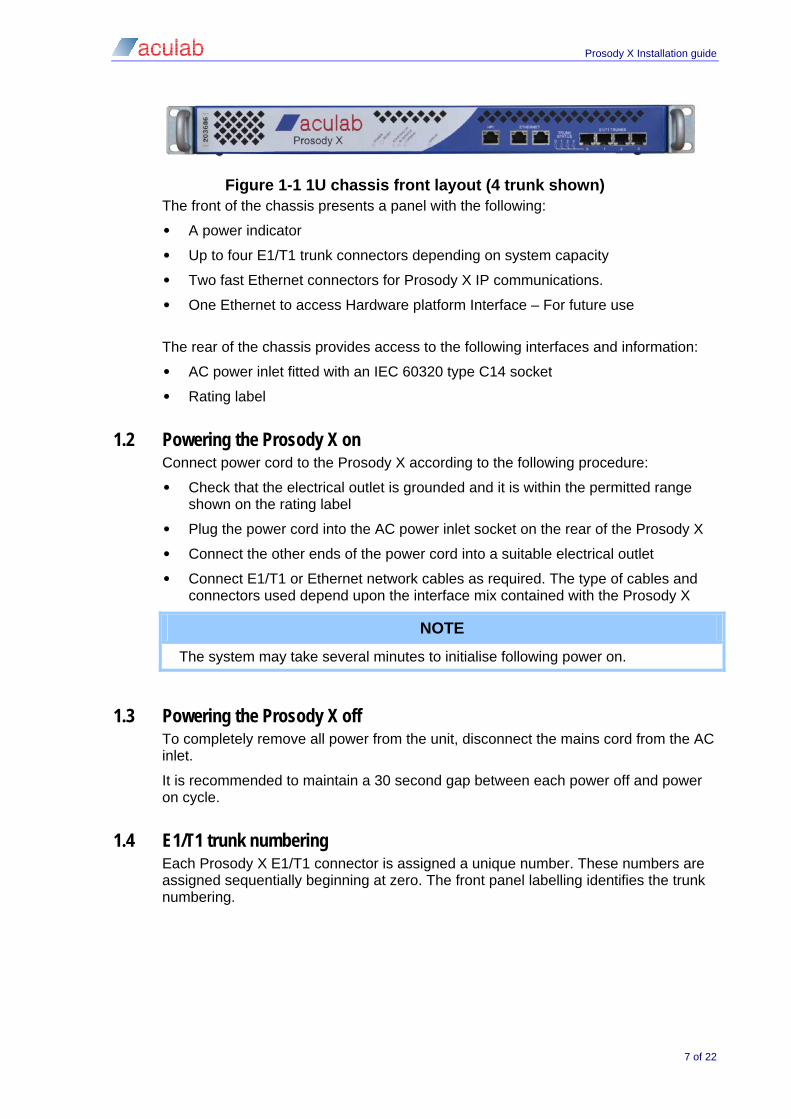
Figure 1-1 1U chassis front layout (4 trunk shown) The front of the chassis presents a panel with the following:
• A power indicator
• Up to four E1/T1 trunk connectors depending on system capacity
• Two fast Ethernet connectors for Prosody X IP communications.
• One Ethernet to access Hardware platform Interface – For future use
The rear of the chassis provides access to the following interfaces and information:
• AC power inlet fitted with an IEC 60320 type C14 socket
• Rating label
1.2 Powering the Prosody X on Connect power cord to the Prosody X according to the following procedure:
• Check that the electrical outlet is grounded and it is within the permitted range shown on the rating label
• Plug the power cord into the AC power inlet socket on the rear of the Prosody X
• Connect the other ends of the power cord into a suitable electrical outlet
• Connect E1/T1 or Ethernet network cables as required. The type of cables and connectors used depend upon the interface mix contained with the Prosody X
NOTE
The system may take several minutes to initialise following power on.
1.3 Powering the Prosody X off To completely remove all power from the unit, disconnect the mains cord from the AC inlet.
It is recommended to maintain a 30 second gap between each power off and power on cycle.
1.4 E1/T1 trunk numbering Each Prosody X E1/T1 connector is assigned a unique number. These numbers are assigned sequentially beginning at zero. The front panel labelling identifies the trunk numbering.
7 of 22
Prosody X Installation guide
1.5 Ethernet connections Each Ethernet connection has a unique MAC address and will be assigned an initial IP address when connected to the network. Please consult the specific application documentation for information on configuring IP addresses.
The Prosody X IP communication interfaces are designed to connect to full duplex Ethernet switch equipment, which can sustain the required data throughput with little or no packet loss. There are two Prosody X IP communication interfaces as this can offer additional redundancy, if required, in a correctly configured network. Assuming both interfaces are connected and have valid layer 1 connections, the Prosody X will default to one interface to carry IP traffic rather than performing load sharing.
Design of a redundant Ethernet network is beyond the scope of this document, however at a minimum, each Prosody X IP communication interface would connect to a separate Ethernet switch.
1.6 Cabling The Prosody X is connected to other network equipment via CAT 5, 5e, 6 or 6e cables. There are two types of interface and they have different pin assignments.
The pin-out of the RJ45/48 connectors for both E1/T1 and Ethernet connections are detailed below. For E1/T1 and 10/100 Ethernet connections:
Receive on the Prosody X should be connected to transmit on the network equipment
Transmit on the Prosody X should be connected to receive on the network equipment
Cross-over cables will be required in instances where two connector sockets with the same signal pinouts are connected together.
NOTE
E1/T1 crossover cables are wired differently to 10/100 Ethernet crossover cables.
NOTE
Shielded cables are recommended in all instances.
Ample strain relief should be fitted when installing all cables, both signal and power. Any damage caused by inadequate strain relief to cards or power connectors will not be covered by your warranty.
Both E1/T1 and Ethernet cables may be connected and disconnected while the unit is active.
Bear in mind that disconnecting an active E1/T1 trunk will cause an alarm condition both within the Prosody X unit and at the corresponding network end of the cable. You may wish to check with the network operator if there is a requirement for advance notification of E1/T1 trunk installation and maintenance.
CAUTION
When making a telephony network connection, to minimize the risk of fire, only telecommunications line cord of 26 AWG or larger may be used.
8 of 22
Prosody X Installation guide
1.6.1 Cable pinouts
120 Ohm E1 or 100 Ohm T1 The 8-contact RJ45 Plug on the cable between each E1/T1 trunk and the 100 or 120 Ohm network trunk must be wired as follows:
Pin Signal Direction 1 Rx+ input 2 Rx- input 4 Tx+ output 5 Tx- output
10/100Base-T (Prosody X IP communication) The 8-contact RJ45 Plug on the cable between the card and an 10/100Base-T network must be wired as follows:
Pin Signal Direction 1 Tx+ output 2 Tx- output 3 Rx+ input 6 Rx- input
Cat 5 cabling is recommended for 10/100Base-T Ethernet connections. All eight wires are normally populated on off the shelf Ethernet patch cables.
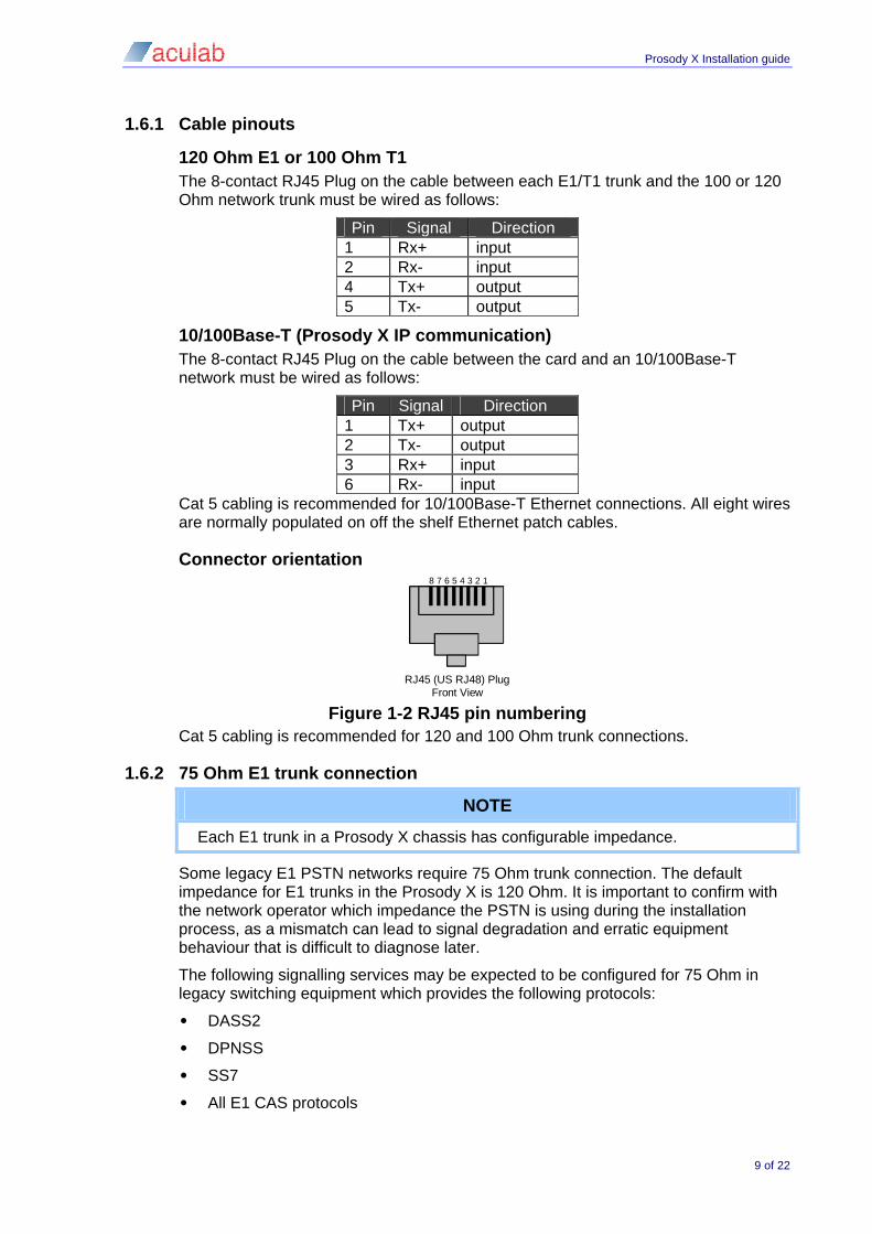
Connector orientation
RJ45 (US RJ48) Plug Front View
8 7 6 5 4 3 2 1
Figure 1-2 RJ45 pin numbering
Cat 5 cabling is recommended for 120 and 100 Ohm trunk connections.
1.6.2 75 Ohm E1 trunk connection
NOTE
Each E1 trunk in a Prosody X chassis has configurable impedance.
Some legacy E1 PSTN networks require 75 Ohm trunk connection. The default impedance for E1 trunks in the Prosody X is 120 Ohm. It is important to confirm with the network operator which impedance the PSTN is using during the installation process, as a mismatch can lead to signal degradation and erratic equipment behaviour that is difficult to diagnose later.
The following signalling services may be expected to be configured for 75 Ohm in legacy switching equipment which provides the following protocols:
• DASS2
• DPNSS
• SS7
• All E1 CAS protocols
9 of 22
Prosody X Installation guide
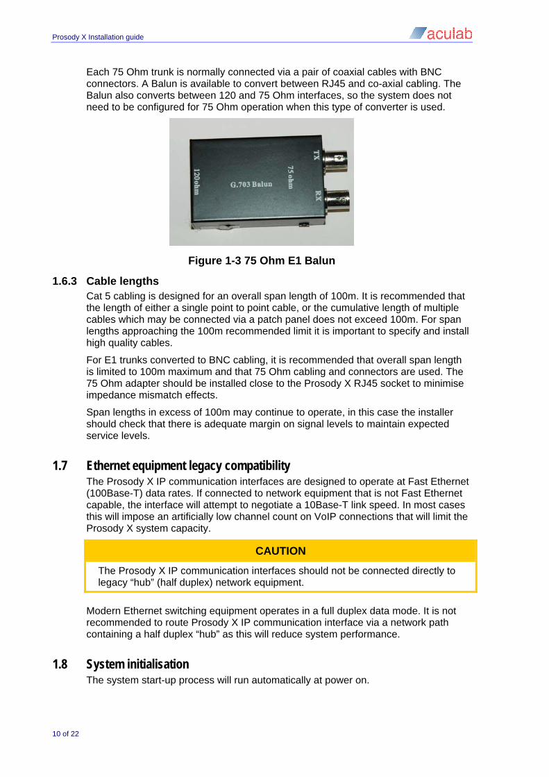
Each 75 Ohm trunk is normally connected via a pair of coaxial cables with BNC connectors. A Balun is available to convert between RJ45 and co-axial cabling. The Balun also converts between 120 and 75 Ohm interfaces, so the system does not need to be configured for 75 Ohm operation when this type of converter is used.
Figure 1-3 75 Ohm E1 Balun
1.6.3 Cable lengths Cat 5 cabling is designed for an overall span length of 100m. It is recommended that the length of either a single point to point cable, or the cumulative length of multiple cables which may be connected via a patch panel does not exceed 100m. For span lengths approaching the 100m recommended limit it is important to specify and install high quality cables.
For E1 trunks converted to BNC cabling, it is recommended that overall span length is limited to 100m maximum and that 75 Ohm cabling and connectors are used. The 75 Ohm adapter should be installed close to the Prosody X RJ45 socket to minimise impedance mismatch effects.
Span lengths in excess of 100m may continue to operate, in this case the installer should check that there is adequate margin on signal levels to maintain expected service levels.
1.7 Ethernet equipment legacy compatibility The Prosody X IP communication interfaces are designed to operate at Fast Ethernet (100Base-T) data rates. If connected to network equipment that is not Fast Ethernet capable, the interface will attempt to negotiate a 10Base-T link speed. In most cases this will impose an artificially low channel count on VoIP connections that will limit the Prosody X system capacity.
CAUTION
The Prosody X IP communication interfaces should not be connected directly to legacy “hub” (half duplex) network equipment.
Modern Ethernet switching equipment operates in a full duplex data mode. It is not recommended to route Prosody X IP communication interface via a network path containing a half duplex “hub” as this will reduce system performance.
1.8 System initialisation The system start-up process will run automatically at power on.
10 of 22

Prosody X Installation guide
1.9 Initial hardware checks When the Prosody X is turned on, the STARTING UP indicator will turn on and the unit will go through the boot sequence. Using the AIT/ACT guide, the card can be configured. Configuring the card is indicated by LOADING. When complete, the IN SERVICE indicator on the front panel will turn on.
1.10 Multiple ProsodyX configurations To configure multiple ProsodyX, please refer to the AIT/ACT guide.
1.11 Common set-up problems 1.11.1 System TDM clock not configured
Where one or more E1 or T1 trunks are connected to network equipment, correct operation depends on TDM clock synchronisation.
A common set-up problem concerns the configuration of the system TDM clock which is required to synchronise the Prosody X to other E1/T1 equipment. This should be set to recover the clock from a network source or PSTN, where available. The recovered clock source will default to E1/T1 trunk 1 and may be re-configured to any other connected E1/T1 trunk via the ACT or Switch API.
It is not possible to synchronise one Prosody X to multiple network sources that are not synchronised to each other. An example of this scenario can be two or more E1/T1 trunks, each connected to a separate carrier network.
1.11.2 Ethernet IP address out of range All Ethernet end points in a network require a valid and unique IP address. Consult the network administrator for information on the available range of IP addresses.
11 of 22

Prosody X Installation guide
2 Hardware maintenance
2.1 Servicing There are no user serviceable parts inside the Prosody X chassis. The unit may optionally be powered off for inspection every year and to remove any dust that accumulates internally. This should only be performed by qualified technical personnel.
2.2 Cooling fan failure The unit relies on forced air cooling to maintain the internal electronics within rated operating temperatures. The unit has two cooling fans visible at the rear the unit is designed to continue operating with a single fan failure. It is strongly recommended that the unit is scheduled for fan replacement in the event of any fan failure. Fan operation can be checked by accessing the system status page via the application specific browser interface.
Contact your supplier for advice on fan replacement if the unit is out of warranty.
2.3 Moving an installed Prosody X A Prosody X should not be moved while operating. If a Prosody X has to be moved, the power must be disconnected to prevent equipment damage or risk to operator safety. Please follow the application specific system shutdown procedure prior to powering down an operating Prosody X.
2.4 Basic fault finding The following list provides examples of possible reasons for the unit not operating correctly.
Symptom Possible cause Unit does not power up Check power cabling and fuses. E1/T1 trunk non-operational
Check layer 1 information. Possible cable disconnection, network/user protocol configuration or incorrect TDM clock recovery/synchronisation configuration.
No Prosody X IP communication
Check cabling and IP address.
12 of 22

Prosody X Installation guide
Appendix A: USA/Canada approval details This section applies only to E1/T1 trunk interfaces configured for T1 operation.
FCC connection requirements This equipment complies with Part 68 of the FCC rules and the requirements adopted by the ACTA. On the exterior of the cabinet of this equipment is a label that contains, among other information, a product identifier in the format US:AAAEQ##TXXXX. If requested, this number must be provided to the telephone company.
ACTA Registration Number: US:5TCXDNANCapplianX
Ringer Equivalence Number (REN): NAN
Facility Interface Code (FIC): 04DU9.1SN, 04DU9.BN, 04DU9.DN & 04DU.1KN
Service Order Code (SOC): 6.0P
USOC Jack Type: RJ48C
A FCC compliant telephone cord and modular plug is provided with this equipment. This equipment is designed for connection to the telephone network or premises wiring using a compatible modular jack that is Part 68 compliant. See Installation Instructions for details.
The REN is used to determine the quantity of devices that may be connected to the telephone line. Excessive RENs on the telephone line may result in the devices not ringing in response to an incoming call. Typically, the sum of RENs should not exceed five (5.0). To be certain of the number of devices that may be connected to a line (as determined by the total RENs) contact the local telephone company.
If this equipment causes harm to the telephone network, the telephone company will notify you in advance that temporary discontinuance of service may be required. But if advance notice isn't practical, the telephone company will notify the customer as soon as possible. Also, you will be advised of your right to file a complaint with the FCC if you believe it is necessary.
The telephone company may make changes to its facilities, equipment, operations or procedures that could affect the operation of the equipment. If this happens the telephone company will provide advance notice so you can make the necessary modifications to maintain uninterrupted service.
If trouble is experienced with this equipment, for repair or warranty information, please contact:
Aculab, Inc,
Customer Service,
100 River Ridge Drive, Suite 101,
Norwood, MA 02062,
Tel: +1 781 433 6000 / Fax: +1 781 352 4250
There are no user serviceable components on the card. If the equipment is causing harm to the telephone network, the telephone company may request that you disconnect the equipment until the problem is resolved.
Connection to party line service is subject to state tariffs. (Contact the state public utility commission, public service commission or corporation commission for information.)
13 of 22

Prosody X Installation guide
Systems Facility Interface Codes (FIC), Service Order Codes (SOC), USOC Jack Codes and Ringer Equivalence Numbers (REN) are shown in the table below for each trunk where applicable:
Trunk FIC SOC USOC Jack REN Trunk 0 – 7 T1 04DU9.1SN 6.0P RJ48C NAN Trunk 0 – 7 T1 04DU9.BN 6.0P RJ48C NAN Trunk 0 – 7 T1 04DU9.DN 6.0P RJ48C NAN Trunk 0 – 7 T1 04DU9.1KN 6.0P RJ48C NAN
UL requirements This product has been assessed against UL60950-1 and is a listed accessory component under UL file number E178354.
Approval number USA Approval type FCC part 68 XD component registration
Approval number US:5TCXDNANCapplianX
Approval holder Aculab plc, Lakeside, Bramley Road, Mount Farm, Milton Keynes. MK1 1PT, UK
FCC approves the apparatus for connection to public T1 services as specified in the approval certificate, this appendix, and the 'Installation guide' subject to the conditions set out in these documents.
14 of 22

Prosody X Installation guide
Appendix B: Approval details for UK and other EU countries
15 of 22

Prosody X Installation guide
Appendix C: Approval details for Australia Approval types
C-Tick Mark (EMC Australia)
A-Tick Mark (Telecom Australia)
Supplier Identification N4292
Approval Holder Approval Specialists
The current contact details for the Australia office is available from the Aculab company web site at www.aculab.com.
Approval by the ACA for connection to primary rate ISDN will be held by Approval Specialists, and subject to the conditions set out in this appendix.
Usage and type The Prosody X is principally designed for use connected to a 2048 Kbps integrated services digital network (primary rate ISDN) with TS038 signalling including the New Zealand Primary Rate ISDN network (not currently covered by approval).
Other types of private circuit use are also appropriate, and other signalling systems are available or planned.
The Australian approvals are only applicable when the Prosody X is used with Aculab supplied signalling software appropriate for use in the country covered by the Approval.
Approved functionality • Call initiation
• Call clearing
• Call answering
• Application program generated by the user
• Independent Operation of the network interfaces (one or more interfaces attached to the network)
16 of 22

Prosody X Installation guide
Appendix D: Warranty and support D.1 Warranty
The standard warranty of 2 years applies to all Prosody X 1U Enterprise components. All cover is return to supplier.
NOTE
Please contact your supplier for warranty enquiries. The standard warranty does not cover damage, deterioration or malfunction resulting from:
• Accident, misuse, neglect, fire, water, lighting, or other acts of nature, unauthorized product modification, or failure to follow instructions supplied with the product.
• Repair or attempted repair by anyone not authorized by your supplier.
• Causes external to the product such as electric power fluctuations or failure.
• Normal wear and tear.
• Any other causes which do not relate to a product defect.
D.2 Returns procedure Under the standard warranty, a faulty Prosody X should be returned to Aculab PLC by following the Returned Material Authorisation procedure.
D.3 Spare parts and accessories Please take a note of the serial number on the Prosody X when contacting your supplier for spare parts, and ensure you mention the parts are for a Prosody X chassis.
The serial number is normally located at the front of each unit.
Spare and replacement power cords are available from Aculab PLC.
E1 75 Ohm BNC cable adapter kits are available from Aculab PLC
D.4 Contact information Warranty and support information is provided with your Prosody X. Your warranty and support terms will include any specific contact details.
D.5 Prosody X technical support Always have the serial number available prior to contacting technical support.
NOTE
Please contact your supplier for first line technical support enquiries.
General Prosody X information:
www.aculab.com
17 of 22

Prosody X Installation guide
Appendix E: Safety information E.1 AC Power requirements
The rating plate details the permitted voltage and frequency range for that particular unit.
CAUTION
Under no circumstance connect the Prosody X to a power source with voltage or frequency different to that stated. Contact your local supplier for advice if your power input is different to that shown on the rating label.
The Prosody X can operate with the following AC power inputs:
Power input type AC chassis (Amps) North America – 115VAC 60Hz 0.6 max, 0.2
continuous
UK and Europe – 230VAC 50Hz 0.3 max, 0.1 continuous
WARNING
THIS EQUIPMENT IS NOT DESIGNED FOR USE WITH AN I.T. POWER SUPPLY (A POWER DISTRIBUTION SYSTEM THAT HAS NO DIRECT CONNECTION TO GROUND, AND WHERE THE EXPOSED CONDUCTIVE PARTS OF THE ELECTRICAL INSTALLATION ARE GROUNDED).
E.2 AC Power cords The Prosody X is supplied with moulded IEC60320 input power cords. Within the United Kingdom these will be ASTA (Association of Short Circuit Testing Authorities) approved power cords with moulded 13A 3 Pin plugs. These should be fused at 5A.
Within Europe these will be moulded 3 Pin plugs with suitable European agency approval marks. Additionally the cords will be <HAR> marked.
Within North America these will be moulded 3 Pin plugs with UL and CSA type approval.
The power cords supplied will be terminated suitable for your local requirements. In cases where no plug is fitted or if a plug needs to be changed, the plug may only be fitted by a person competent to fit a plug of the type suitable for the required power outlet. If a power cord needs to be replaced, an appropriately approved power cord must be used.
E.3 Circuit definition The Ethernet (Prosody X IP communication and Hardware Platform interface ) and USB interfaces are Safety Extra Low Voltage (SELV) circuits. SELV circuits are so designed and protected that under normal conditions the maximum voltage between any two accessible circuit parts, one of which may be body or ground, does not exceed 42.4 volts (peak AC) or 60VDC, even in the presence of a single fault.
E1/T1 interfaces are Telecommunication Network Voltage (TNV) circuits operating within the limits of SELV. The E1/T1 interfaces have transient voltage protection circuits built in.
18 of 22

Prosody X Installation guide
NOTE
Where equipment is intended to be electrically connected to other equipment, interconnection circuits shall be selected to provide continued conformance with the requirements of Clause 2.3 of IEC60950-1 for SELV circuits, and with the requirements of clause 6 for TNV circuits, after making connections between equipment.
NOTE
Make sure that the integrity of the SELV system is maintained when connection is made through any other interface within the system. If in any doubt seek competent advice.
E.4 Grounding the Prosody X The Prosody X must be grounded as detailed below:
• Use a grounded 3 connection IEC60320 AC power cable
E.5 Serviceable parts The Prosody X has no user serviceable parts inside.
E.6 Regulatory marking The CE Marking has been applied to the Prosody X to demonstrate compliance with the following European standards:
• EN55022 and EN55024 for electromagnetic compatibility.
• EN60950 for electrical safety.
E.7 USA federal communication commission warnings This equipment has been tested and found to comply with the limits for a class A digital device, pursuant to part 15 of the FCC rules. These limits are designed to provide reasonable protection against harmful interference when the equipment is operated in a commercial environment. This equipment generates uses and can radiate radio frequency energy, and if not installed in accordance with the instruction manual may cause harmful interference to radio communications.
The device complies with part 15 of the rules. Operation is subject to the following two conditions:
• This device may not cause harmful interference, and
• This device must accept any interference received, including interference that may cause undesired operation.
No changes or modifications to the Prosody X are allowed without explicit written permission from Aculab. Any changes or modifications could void the end users authority to operate the device and invalidate the warranty.
19 of 22

Prosody X Installation guide
Appendix F: Sicherheitshinweise F.1 Wechselspannungsanforderungen (AC)
Das Typenschild gibt die erlaubte Stromstärke und den Frequenzbereich für dieses System wieder.
VORSICHT
Schliessen Sie Prosody X unter keinen Umständen an eine andere als die angegebene Stromquelle mit dem vorgegebenen Frequenzbereich an. Setzen Sie sich mit einem für ihre Region zuständigen Lieferanten in Verbindung, wenn Ihre Spannungsversorgung vor Ort nicht der auf dem Typenschild angegebenen entspricht.
Prosody X kann mit folgenden Eingangsspannungen (AC) betrieben werden:
Power input type AC chassis (Amps) North America – 115VAC 60Hz 0.6 max, 0.2
continuous
UK and Europe – 230VAC 50Hz 0.3 max, 0.1 continuous
WARNUNG
DIESES GERÄT IST NICHT FÜR DEN EINSATZ MIT EINEM KALTGERÄTESTECKER VORGESEHEN (EIN SPANNUNGSVERSORGUNGSSYSTEM, DAS NICHT DIREKT GEERDET IST und WO DIE EXPONIERTEN, LEITENDEN TEILE DER ELEKTRISCHEN INSTALLATION GEERDET SIND)
F.2 Wechselspannung Anschluss Prosody X wird mit IEC60320 eingeformten Netzkabel geliefert. Innerhalb Europas handelt es sich um dreipolige Stecker mit den passenden European Agency Prüfzeichen. Zusätzlich sind die Kabel mit <HAR> anerkannten Markierungen versehen.
Innerhalb Nordamerikas handelt es sich um dreipolige Stecker mit UL und CSA Typenzulassung.
Die mitgelieferten Netzkabel entsprechen Ihren Bedürfnissen vor Ort. Falls noch kein Stecker vorhanden ist oder ein Stecker ausgetauscht werden muss, darf der Stecker nur von jemandem angebracht werden, der dazu autorisiert ist. Wenn ein Spannungsversorgungs-kabel ausgetauscht werden muss, muss ein dementsprechend zugelassenes Spannungs-versorgungskabel verwendet werden.
F.3 Definition des Stromkreises. Die Ethernet-(VoIP-Traffic und Systemadministration) und USB-Anschlüsse sind Safety Extra Low Voltage (SELV) Schaltungen. SELV-Schaltungen sind so konzipiert und geschützt, dass unter normalen Bedingungen die maximale Stromstärke zwischen zwei beliebigen zugänglichen Teilen des Stromkreises, von denen jeweils einer Masse oder Erde sein kann, 42.4 Volt (Spitzenwert Wechselstrom) oder 60V DC nicht überschritten wird, auch im Falle eines Fehlers.
20 of 22

Prosody X Installation guide
E1/T1 Schnittstellen sind Telecommunication Network Voltage (TNV) Schaltungen, die den Bedingungen von SELV entsprechen. Die E1/T1 Schnittstellen verfügen über eingebaute Transient-Spannungs-Schutz-Schaltungen.
HINWEIS
Wenn Sie eine elektrische Verbindung zwischen den Geräten erstellen möchten, sollten Sie gekoppelte Schaltungen wählen, um die kontinuierliche Konformität mit den Anforderungen der Klausel 2.3 des IEC60950-1 für SELV-Schaltungen, und mit den Anforderungen der Klausel 6 für TNV-Schaltung, die nach Verbindungen zwischen Geräten dauerhaft eingehalten werden, erfüllen.
HINWEIS
Stellen Sie sicher, dass die Integrität des SELV-Systems erhalten bleibt, wenn eine Verbindung durch irgendeinen anderen ’Interface Port’ innerhalb des Systems hergestellt wird. Bei Unklarheiten wenden Sie sich bitte an unsere qualifizierten Mitarbeiter.
F.4 Prosody X - Erdung Prosody X muss wie folgt geerdet werden:
• Verwenden Sie ein geerdetes 3-poliges Wechselstromkabel des Typs IEC60320
F.5 Wartungsteile Prosody X beinhaltet keine Teile, die vom Benutzer gewartet werden müssen.
F.6 Regulierungszeichen Das CE-Prüfzeichen gewährleistet, dass Prosody X den folgenden europäischen Standards entspricht.
• EN55022 und EN55024 für elektromagnetische Kompatibilität.
• EN60950 für elektrische Sicherheit
21 of 22

Prosody X Installation guide
22 of 22
Appendix G: Earthing requirements for Scandinavia Finland “Laite on liitettävä suojamaadoituskoskettimilla varustettuun pistorasiaan”
Norway “Apparatet må tilkoples jordet stikkontakt”
Sweden “Apparaten skall anslutas till jordat uttag”
Denmark “For tilslutning af de øvrige ledere, se medfølgende installationsvejledning”
Appendix H: Technical Specifications Operating temperature: 0 deg to 40 °C
Minimum storage Temperature: -20 °C
Operating humidity: 20% to 80% non condensing
Storage humidity: 10% to 90% non condensing
AC power input voltage: 90 to 264 VAC
AC power input frequency: 47 to 63Hz
Maximum rated power consumption: 55W
Typical steady state power consumption: 25W Standby power consumption: 2W
E1 Trunks meet ITU G.703/G.704 recommendations:
• Default 120 Ohm termination (75 Ohm configuration option)
T1 Trunks meet ANSI T1.403 recommendations:
• Fixed 100 Ohm termination
Appendix I: Prosody X documentation references General Prosody X documentation:
www.aculab.com