Installation | Configuration | Support | Maintenance | Use...
71
800.205.7186 • www.codeblue.com IP1500 and IP2500 Series Speakerphones Administrator Guide Installation | Configuration | Support | Maintenance | Use
Transcript of Installation | Configuration | Support | Maintenance | Use...

800.205.7186 • www.codeblue.com
IP1500 andIP2500 Series
Speakerphones
Administrator GuideInstallation | Configuration | Support | Maintenance | Use

Code Blue • 259 Hedcor Street • Holland, MI 49423 USA • 800.205.7186 • www.codeblue.com GU-137-Ppage 2 of 71
IP1500 and IP2500 SeriesAdministrator Guide
Table of Contents Section Page 2 Introduction....................................................................................4 3 Getting Started...............................................................................5 3.1 What’s included with the IP1500 and IP1501...................... 6 3.2 What’s included with the IP2500 and IP2501.......................7 4 Connectors, Ports and Switch List ..............................................8 4.1 IP1500/2500 Printed Circuit Board Layout...........................8 4.2 Wiring Diagram - IP1500 and IP1501..................................9 4.3 Wiring Diagram - IP2500 and IP2501................................10 5 Installation....................................................................................11 5.1 Surface Mount IP1500 .......................................................11 5.2 Flush Mount IP1501...........................................................12 5.3 Surface Mount IP2500 .......................................................14 5.4 Flush Mount IP2501...........................................................15 6 Provisioning the Phone...............................................................19 6.1 Determine the IP Address..................................................19 6.2NetworkConfiguration.......................................................22 6.3ConfiguringVoIPSettings..................................................24 6.4ConfiguringtheSystemSettings........................................29 6.5ConfiguringSystemOptionsandScripts............................33 7 CLI (Command Line Interface)....................................................46 8 In-Call Commands.......................................................................47 9 Factory Reset...............................................................................4810 Compatibility................................................................................5011 Configuring for Cisco Unified Communications Manager 9....5112 Avaya IP Office Integration Guide.............................................. 5513 Using the IP1500 and IP2500 Speakerphones .........................6214 Button and Activation Specifications........................................6315 Speaker Specifications...............................................................6416 Remote Mount Beacon/Strobe Installation...............................6517 Troubleshooting the IP1500 and IP2500 Speakerphone..........66

Code Blue • 259 Hedcor Street • Holland, MI 49423 USA • 800.205.7186 • www.codeblue.com GU-137-Ppage 3 of 71
IP1500 and IP2500 SeriesAdministrator Guide
18 Technical Specifications.............................................................6719 Regulatory....................................................................................68 14.1 ETL Required Labeling......................................................6820 Warranty.......................................................................................6921 Technical Services and Support................................................7022 Download Information.................................................................71

Code Blue • 259 Hedcor Street • Holland, MI 49423 USA • 800.205.7186 • www.codeblue.com GU-137-Ppage 4 of 71
IP1500 and IP2500 SeriesAdministrator Guide
2 IntroductionThankyouforchoosingtheCodeBlueIP1500andIP2500SeriesfullduplexVoIPspeakerphone(s),intercomandpagingdevice(s)forindoorandoutdoorapplications.Thesespeakerphonesarebuilttomeetthelatestregulations,withstandtheharshestelementsandbeproactivesolutionsforwhenyouneedthemmost.Thisguideprovidesbasicandadvancedconfigurationinformationforobtain-ingthebestperformancewiththeIP1500andIP2500Seriesspeakerphone(s).
Thesedevicesarelistedasnon-emergencysignalingandarenon-monitoredindoor/outdoorcom-munication units.
IP1500 Surface Mount
IP1501 Flush Mount
IP2500-s Surface Mount
IP2501-d Flush MountIP2501-s Flush Mount
IP2500-d Surface Mount

Code Blue • 259 Hedcor Street • Holland, MI 49423 USA • 800.205.7186 • www.codeblue.com GU-137-Ppage 5 of 71
IP1500 and IP2500 SeriesAdministrator Guide
3 Getting Started ThischapterprovidesinformationforobtainingthebestperformancewiththeIP1500andIP2500Seriesspeakerphone.ItisstronglyrecommendedthattheentireguideisreadbeforeconfiguringyourIP1500andIP2500Seriesspeakerphonetoensureyougetmaximumperformance.
Throughout this guide you will see the following two references:Calling party: Thisisthepersonactivatingthespeakerphonebypressingabutton.Called party:Thisisthepersonreceivingthecallfromthespeakerphone;typicallyaguard,911operator,dispatchofficer,etc.
Thesespeakerphonesprovidespowerful,yetflexibleIPcommunication,anddeliverexcellentvoicequalityforyourspeakerphone,intercomandpagingsolution.

Code Blue • 259 Hedcor Street • Holland, MI 49423 USA • 800.205.7186 • www.codeblue.com GU-137-Ppage 6 of 71
IP1500 and IP2500 SeriesAdministrator Guide
3.1 What’s included with the IP1500 and IP1501 Series
IP1500 Surface Mount
Quantity Part No. Description 1 SurfaceMountBox Included1 Mounting Bracket Included4 No. 4 Security Screws Included4 No. 4 Screws Not Included1 FourSquareBox Not Included1 InstallationandSetUpGuide Included
AStandardDrilledSpannerInsertBitisrequiredtotheaccessunit–Not Included
IP1501 Flush Mount
Quantity Part No. Description 1 Faceplate Included1 WeatherproofBackBox Included4 No. 6 Security Screws Included1 No. 6 Screws Included
AStandardTamper-ResistantInsertBitisrequiredtoaccessunit–Not Included

Code Blue • 259 Hedcor Street • Holland, MI 49423 USA • 800.205.7186 • www.codeblue.com GU-137-Ppage 7 of 71
IP1500 and IP2500 SeriesAdministrator Guide
3.2 What’s included with the IP2500 and IP2501 Series
IP2500-s and IP2500-d Surface Mount
Quantity Part No. Description 1 SurfaceMountBox Included1 Mounting Plate Included2 Retaining Screws Included4 No. 8 Screws Included1 Standard Security Bit Included1 InstallationandSetUpGuide Included
IP2501-s and IP2500-d Flush Mount
Quantity Part No. Description 1 FaceplateAssembly Included1 WeatherproofBackBox Included4 Retaining Screws Included1 Standard Security Bit Included1 InstallationandSetUpGuide Included
MountinghardwareforBackBox Not Included

Code Blue • 259 Hedcor Street • Holland, MI 49423 USA • 800.205.7186 • www.codeblue.com GU-137-Ppage 8 of 71
IP1500 and IP2500 SeriesAdministrator Guide
4 Connectors, Ports and Switch ListTheIP1500andIP2500Serieshasacompactdesignsmallenoughandislightenoughtoensureaneasyinstallationatanyneworexistinglocation.TheIP1500/2500hasonePoELANport(IEEE802.310/100EthernetPort)forconnectingtoanetwork.Asingle,normallyopenauxiliaryoutputisavailabletotriggerdoorlocks,lights,gatesoranyothersecuritydevice.
Theinternalcomponentsconsistofamicrophoneconnector,aspeakerconnector,onePoELANport,abuttonconnector(s),onenormallyopenauxiliaryoutputandPCBmountinghardware.
4.1 IP1500 and IP2500 Series Printed Circuit Board Layout
LED Button Connector
AuxiliaryOutputN.O.
PoE LAN Port
SpeakerConnector
MicrophoneConnector
The IP1500 and IP1501 Series is solely poweredbyPoE,802.3atandafClass0uponinitialization.

Code Blue • 259 Hedcor Street • Holland, MI 49423 USA • 800.205.7186 • www.codeblue.com GU-137-Ppage 9 of 71
IP1500 and IP2500 SeriesAdministrator Guide
4.2 Wiring Diagram IP1500 and IP1501 Series
TheIP1500andIP1501SerieshasonePoELANportfornetworkconnectivityandonenormallyopenauxiliaryoutputrelayfortriggeringdevicessuchasaLEDbeacon/strobe,camerapresetacti-vationinputs,gatecontrolorthirdpartycontrollers.Therelaycanbeprogrammedtoholdtherelayclosedforthedurationofthecall,foraspecifictimeperiodortoggledforaspecifictimeperiodupontheoperator’srequest.

Code Blue • 259 Hedcor Street • Holland, MI 49423 USA • 800.205.7186 • www.codeblue.com GU-137-Ppage 10 of 71
IP1500 and IP2500 SeriesAdministrator Guide
4.3 Wiring Diagram IP2500 and IP2501 Series
TheIP2500andIP2501SerieshasonePoELANportfornetworkconnectivityandonenormallyopenauxiliaryoutputrelayfortriggeringdevicessuchasaLEDbeacon/strobe,camerapresetacti-vationinputs,gatecontrolorthirdpartycontrollers.Therelaycanbeprogrammedtoholdtherelayclosedforthedurationofthecall,foraspecifictimeperiodortoggledforaspecifictimeperiodupontheoperator’srequest.TheIP2500andIP2501Seriesalsohastheoptionofanadditionalbuttonfor non-emergency calls.

Code Blue • 259 Hedcor Street • Holland, MI 49423 USA • 800.205.7186 • www.codeblue.com GU-137-Ppage 11 of 71
IP1500 and IP2500 SeriesAdministrator Guide
5 Installation TheIP1500andIP2500Seriescomesinsurfaceandflushmountoptions.Thesurfacemountal-lowsthemountingbrackettobeinstalledduringroughinandthefaceplatewithelectronicsduringcompletion.Thefaceplateontheflushmountisfiveinchessquareandprovidesanoverlaptothemountingboxtoeliminateadditionaltrimwork.
5.1 Surface Mount IP1500 Series
IP1500SurfaceMount:4.50”wx4.50”hx2.00”d
BackView
4.56
1.38 1.80
.64
3.28
6X .15 THRU ALL .28 X 82°
4.56
VerticalOrientation
NOTE:Threadsealmustbeappliedtoexternalcasescrews.

Code Blue • 259 Hedcor Street • Holland, MI 49423 USA • 800.205.7186 • www.codeblue.com GU-137-Ppage 12 of 71
IP1500 and IP2500 SeriesAdministrator Guide
5.2 Flush Mount IP1501 Series
IP1500FlushMount:4.00”wx5.00”h
5.00
5.00
2.16
.58
1.47
1.72
3/4" Conduit ThreadBottomView
IP1500Faceplate-BacksideGrounding IP1501BaseFaceplate-BacksideGrounding
Groundlugwillbeplacedonastudwithbaremetalononesideandakepnutholdingitinplace.Thelugusedforthe1500requiresa#6eyelettypelug.

Code Blue • 259 Hedcor Street • Holland, MI 49423 USA • 800.205.7186 • www.codeblue.com GU-137-Ppage 13 of 71
IP1500 and IP2500 SeriesAdministrator Guide
Four
• Mounttheweatherproofbackboxtoaninsidewall or onto a surface.
• Connect a minimum of CAT 5e cable to the Eth-ernetswitchport(PoELAN)forconnectivitytothe network.
• Attachthefaceplatetothebackboxwiththefour-#6securityscrewsprovided.
• ConnectanyauxiliarydevicetotheN.O.auxoutput1
VerticalOrientation
NOTE:Threadsealmustbeappliedtothefourfaceplatesecurityscrews.

Code Blue • 259 Hedcor Street • Holland, MI 49423 USA • 800.205.7186 • www.codeblue.com GU-137-Ppage 14 of 71
IP1500 and IP2500 SeriesAdministrator Guide
5.3 Surface Mount IP2500 Series
IP2500SeriesSurfaceMount:7.25”wx7.25”hx2.00”d
7.41
7.17
3.59
3.70
1.56 4.28
2.09
3.39
.88KNOCK OUT
1.70 2.00 2.00
1.10
.88KNOCK OUT
2.03
7.41
7.17
3.59
3.70
1.56 4.28
2.09
3.39
.88KNOCK OUT
1.70 2.00 2.00
1.10
.88KNOCK OUT
2.03
BackView
• First,removethetworetainingscrews,onefromeach side of the case
• Removetherearmountingplatebyslidingitdownward
• Usethemountingplateasyourguideonthewall,markthemountingandconduitholes
• Removetherearmountingplateandcreatethe requiredholes,attachthemountingplatetothewall
• Pull CAT 5e cable through the conduit hole in therearmountingplate
• ConnectCAT5ecabletotheEthernetportonthe PCB
• SlidetheIP2500Seriescasedown,starting fromthetopoftherearmountingplate
• Replacethetworetainingscrews
BottomView
VerticalOrientation
NOTE:Bydesign,nomaingasketisneededtosealtheenclosures.Theinstallerisresponsibleforsealingallscrewswiththreadseal,aswellasapplyingtheproperconduitforaweather-tightseal.

Code Blue • 259 Hedcor Street • Holland, MI 49423 USA • 800.205.7186 • www.codeblue.com GU-137-Ppage 15 of 71
IP1500 and IP2500 SeriesAdministrator Guide
5.4 Flush Mount IP2501 Series
IP2501SeriesFlushMount:9.00”wx9.00”h
9.00
9.00
3.60
4.13
1.75
.88
9.00
9.00
3.60
4.13
1.75
.88
BackView BottomView
IP2500SeriesFaceplate-BacksideGrounding IP2501SeriesBaseFaceplate-BacksideGrounding
Groundlugwillbeplacedonastudwithbaremetalononesideandakepnutholdingitinplace.Thelugusedforthe2500requiresa#6eyelettypelug.

Code Blue • 259 Hedcor Street • Holland, MI 49423 USA • 800.205.7186 • www.codeblue.com GU-137-Ppage 16 of 71
IP1500 and IP2500 SeriesAdministrator Guide
1. Removethefourfaceplatescrewsfromthe backbox
2. Usingthebackboxasyourguideonthe wall,marktheroughopeningsize
3. Createtherequiredopeningandconduit runs
4. Pull CAT 5e cable through the conduit hole inthebackbox
5. ConnectCAT5ecabletotheEthernetport on the PCB
6. Attachfaceplatetobackbox
7. Replacethefourfaceplatescrews
VerticalOrientation

Code Blue • 259 Hedcor Street • Holland, MI 49423 USA • 800.205.7186 • www.codeblue.com GU-137-Ppage 17 of 71
IP1500 and IP2500 SeriesAdministrator Guide
Special Warning: High Voltage – Range 37 - 57V DC <12.96 watts (27mA)
Grounding TheIP2500seriesisUL2017safetyrated.DuetothestandardPoE802.3afpowersuppliedbytheremote(IEEE802.3afor“at”rated)PoESwitch,theIP2500hasaprotectiveearthingterminalcableavailable.Theremustbeanuninterruptiblesafetyearthgroundattachedtothegroundinglanyardprovided.Wheneveritislikelythattheprotectionhasbeenimpaired,disconnecttheEthernetcableuntilthegroundhasbeenrestored.Thisisanon-emergency,non-monitoredproductline.
GroundterminationspointshavebeenmarkedinaccordancewithUL2017standards.Approvediconshavebeenappliedtoindicationthegroundinglocation.
Ground Wire ConnectionLocatethe18ggreengroundwire,whichisterminatedwitharinglugthathasbeensecuredtoafaceplatestud.Thelooseendofthegreengroundwiremustbesecuredtoanearthgroundnearby.
Iftheenclosurehasmarkedgroundinglocation,andagreengroundingscrewisavailable,pleaseuseitwheneverlocalcodesdictateearthgroundisrequired.Groundterminationlocationscanbelabelledusingthefollowinggraphicsymbol:
Ground Images sample:
Therearenouser-serviceablepartsinsidetheseproducts.Anyservicing,adjustment,maintenanceorrepairmustbeperformedonlybyservice-trainedpersonnel.Theseproductsdonothaveapowerswitch;theyarepoweredonwhentheEthernetPoEcableispluggedin.
ELECTRICAL SAFETY WARNINGS Thisdeviceissuitableforuseinnon-hazardouslocationsonly.
WARNING:ExplosionHazard–Donotreplacethedeviceunlesspowerhasbeenswitchedoffor theareaisknowntobenon-hazardous.
WARNING: Donotoperatetheequipmentinthepresenceofflammablegassesorfumes.Operating electricalequipmentinsuchanenvironmentconstitutesadefinitesafetyhazard.
WARNING: IftheequipmentisusedinamannernotspecifiedbyCodeBlueCorp.,theprotection providedbytheequipmentmaybeimpaired.
WARNING: Donotperformanyservicesontheunitunlessqualifiedtodoso.Donotsubstitute unauthorizedpartsormakeunauthorizedmodificationstotheunit.
WARNING: Properlygroundtheunitbeforeconnectinganythingelse.Unitsnotproperlygrounded mayresultinasafetyriskandcouldbehazardousandmayvoidthewarranty.Seethe groundingtechniquesectionforproperwaystogroundtheunit.
WARNING: Donotoperatetheequipmentinamannernotspecifiedbythismanual.
WARNING: Donotworkonequipmentorcablesduringperiodsoflightningactivity.
WARNING: InstallonlyinaccordancewithLocal&NationalCodesofAuthoritiesHaving Jurisdiction. (Revised2010-11-15)5

Code Blue • 259 Hedcor Street • Holland, MI 49423 USA • 800.205.7186 • www.codeblue.com GU-137-Ppage 18 of 71
IP1500 and IP2500 SeriesAdministrator Guide
Shield Patch CableNote:Beforeapplyingpowertothegroundedswitch,youmustuseavoltmetertoverifythereisnovoltagedifferencebetweenthepowersupply’snegativeoutputterminalandtheswitchchassisgroundingpoint.Iftheuseofshieldedcablesisrequired,itisgenerallyrecommendedtoonlyconnecttheshieldatoneendtopreventgroundloopsandinterferewithlowlevelsignals(i.e.thermocouples,RTD,etc.).Cat5ecablesmanufacturedtoEIA-568Aor568Bspecificationsarerequired for use with switches.
IntheeventallCat5epatchcabledistancesareshort(i.e.allEthernetdevicesarelocatedthesamelocalcabinetand/orreferencedtothesameearthground),itispermissibletousefullyshieldedcablesterminatedtochassisgroundatbothendsinsystemsvoidoflowlevelanalogsignals.

Code Blue • 259 Hedcor Street • Holland, MI 49423 USA • 800.205.7186 • www.codeblue.com GU-137-Ppage 19 of 71
IP1500 and IP2500 SeriesAdministrator Guide
6 Provisioning the PhoneIfnoDHCPserverisavailable,downloadandinstallTFTPD32fromtftpd32.jounin.nettoturnacom-puterintoaDHCPserver.
6.1 Determine the IP Address
AllIP1500andIP2500SeriesspeakerphonesareDHCPbydefault.Aprogrammingvideoisavail-able at www.codeblue.com/support/how-to-videos.
1. Connectthespeakerphonetoyournetwork.TheLEDwillflashmomentarilyandanaudiblebeepwillbeheardoutofthespeakertoindicatetheOSisloading.TheIP1500/2500speakerphonewillacquireIPNetworksettingsfromyourDHCPserver.
2. CheckyourDHCPleaserecordsorutilizeanetworkscannersuchasSoftPerfect’sNetworkScannertomatchtheMACaddressofthespeakerphonetothecorrectIPaddressinyourleasetableoroutputofthenetworkscanner.
Lease Table and Network Scanner Example
Code Blue • 259 Hedcor Street • Holland, MI 49423 USA • 800.205.7186 • www.codeblue.com GU-137-Ppage 20 of 71
IP1500 and IP2500 SeriesAdministrator Guide
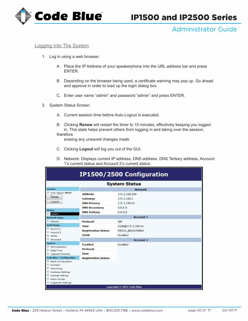
Logging Into The System
1. Log in using a web browser.
A. PlacetheIPAddressofyourspeakerphoneintotheURLaddressbarandpress ENTER.
B. Dependingonthebrowserbeingused,acertificatewarningmaypopup.Goahead andapproveinordertoloadupthelogindialogbox.
C. Enterusername“admin”andpassword“admin”andpressENTER.
2. System Status Screen.
A. CurrentsessiontimebeforeAuto-Logoutisexecuted.
B. Clicking Renewwillrestartthetimerto10minutes,effectivelykeepingyoulogged in.Thisstatehelpspreventothersfromlogginginandtakingoverthesession,therefore erasinganyunsavedchangesmade.
C. Clicking LogoutwilllogyououtoftheGUI.
D. Network:DisplayscurrentIPaddress,DNSaddress,DNSTertiaryaddress,Account 1’s current status and Account 2’s current status.

Code Blue • 259 Hedcor Street • Holland, MI 49423 USA • 800.205.7186 • www.codeblue.com GU-137-Ppage 21 of 71
IP1500 and IP2500 SeriesAdministrator Guide
LoggingOutOfTheSystem
1. Tologoutofthespeakerphone,simplyclickonLogout under Session(see farleft-handcolumn). Thespeakerphonewillalsologyououtautomaticallyafter10minutes. Youwillbepromptedforconfirmation.
2. Click OKtocompletethelogoutprocessorCanceltocontinueconfiguringyour speakerphone.

Code Blue • 259 Hedcor Street • Holland, MI 49423 USA • 800.205.7186 • www.codeblue.com GU-137-Ppage 22 of 71
IP1500 and IP2500 SeriesAdministrator Guide
6.2 Network Configuration
OnceyouhaveobtainedtheDHCPaddressofthespeakerphoneyoucanloginandsetastaticIPaddress.
1. Click on the NetworkmenuitemunderNetworkSetup(seefarleft-handcolumn).
2. UnderGeneral,clickonStatic IP for Connection Type.
3. Enter your desired IP settings under Static IP Address.
4. Onceyouhaveenteredyoursettings,clickonSave Changes.
NotethatifyouhavemovedyourspeakerphonetoanetworkyourPCcannotaccess,youwillhavetoconfigureyourPCtoaccessthatnetworkbeforeconfigurationcancontinue.
Code Blue • 259 Hedcor Street • Holland, MI 49423 USA • 800.205.7186 • www.codeblue.com GU-137-Ppage 23 of 71
IP1500 and IP2500 SeriesAdministrator Guide
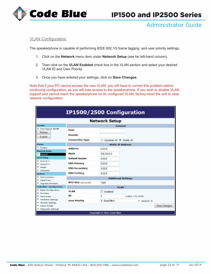
VLANConfiguration
ThespeakerphoneiscapableofperformingIEEE802.1Qframetagginganduserprioritysettings.
1. Click on the Network menu item under Network Setup(seefarleft-handcolumn).
2. Then click on the VLAN EnabledcheckboxintheVLANsectionandselectyourdesired VLANIDandUserPriority.
3. Onceyouhaveenteredyoursettings,clickonSave Changes.
NotethatifyourPCcannotaccessthenewVLAN,youwillhavetocorrectthisproblembeforecontinuingconfiguration,asyouwillloseaccesstothespeakerphone.IfyouwishtodisableVLANsupportandcannotreachthespeakerphoneonitsconfiguredVLAN,factory-resettheunittoclearnetworkconfiguration.

Code Blue • 259 Hedcor Street • Holland, MI 49423 USA • 800.205.7186 • www.codeblue.com GU-137-Ppage 24 of 71
IP1500 and IP2500 SeriesAdministrator Guide
6.3 Configuring VoIP Settings
TheIP1500andIP2500SeriesspeakerphonesareanadvancedVoIPdevicescapableofconnectiv-itytoVoIPsystemsviaSIPandIAX2protocols.Built-incodecsprovidemultipleoptionsforcommu-nicatingwithyourVoIPsystemorCodeBlue’sToolVoxMediaGateway.STUNservercapabilitiesarealsobuiltinforhelpingtraversefirewallswhenconnectingtheunitoutsideofthehostingnet-work.
ConfiguringVoIPAccounts
ThespeakerphonecanregistertoVoIPsystemsusingeithertheSIPorIAXprotocols,andhastheabilitytoregistertotwoseparateVoIPsystemssimultaneouslytoprovideredundancy.
Eachofthespeakerphone’stwoaccounts,availableunderVoIPSetupasAccount1andAccount2,canbeconfiguredaseitherSIPorIAX,subjecttothelimitationthatyoucanonlyhaveoneofthetwoaccountsconfiguredasIAX.Ifyouwishtouseonlyoneaccount,setAccount2toDisabled.

Code Blue • 259 Hedcor Street • Holland, MI 49423 USA • 800.205.7186 • www.codeblue.com GU-137-Ppage 25 of 71
IP1500 and IP2500 SeriesAdministrator Guide
ConfiguringaSIPAccount
Eitherofthespeakerphone’stwoaccountscanbeconfiguredtoregistertoaVoIPsystemviaSIP.
Configurationisasfollows:
• SettheVoIPProtocoltoSIP&RTP.
• ForDescription,enteranamethespeakerphonewilluseinternallytorefertothisaccount.
• ForUsername/Number,enterthenumberthatthespeakerphonewilluseforSIPaddressing.ThiswilloftenbetheextensionnumberinaVoIP-basedPBX.
• ForDisplayName,enterthedisplaynamethespeakerphonewillsendinSIPtransactions.Thiswilloftenbethecallingnameoftheextension.
• ForDomain,enterthedomainthespeakerphonewillregisterto.
• ForOutboundProxy,enteraSIPproxythespeakerphoneshouldsendoutboundcallsto.Ifthisisthesameasthedomain,youcanleavethisfieldblank.
• ForOutboundProxyPort,enteranIPportnumberthespeakerphonewillsendoutboundcallsto.Typically,thisshouldbeleftat0.
• ForRegistrationLifetime,enterthetimeinsecondsthespeakerphonewillrequestthatitsregistrationbevalidfor.Thespeakerphonewillautomaticallyre-registerbeforethistimeperiod expires.
• CheckKeep-AliveifyouwantthespeakerphonetoperiodicallysendOPTIONSrequeststotheSIPserver,e.g.tokeepaNATconnectionalive.
• CheckSTUNifyouwanttoenableSTUNsupportforthisaccount.
• YoucanadjusttheDTMFThreshholdvalueifyouhavedifficultieswiththespeakerphoneactivatingin-callcommandswhennoDTMFispresent.
• ForUsernameandPassword,settheusernameandpasswordthespeakerphonewillusetoauthenticatetothedomainandoutboundproxy.Note that the username is used for authentication only and need not matchtheUsername/NumberfieldiftheVoIPsystemdoesnotexpectitto.
• VLANuserprioritiescanbeadjustedfor SIP and RTP audio.

Code Blue • 259 Hedcor Street • Holland, MI 49423 USA • 800.205.7186 • www.codeblue.com GU-137-Ppage 26 of 71
IP1500 and IP2500 SeriesAdministrator Guide
ConfiguringanIAXAccount
Eitherofthespeakerphone’stwoaccountscanbeconfiguredtoregistertoaVoIPsystemviaIAX.(Note,however,thatonlyoneofthetwoaccountsmaybeconfiguredasIAX-thespeakerphonedoesnotsupporttwosimultaneousIAXaccounts.)
Configurationisasfollows:
• SettheVoIPProtocoltoIAX.
• ForDescription,enteranamethespeakerphonewilluseinternallytorefertothisaccount.
• ForUsername/Number,enterthenumberthatthespeakerphonewilluseforIAXaddressing.ThiswilloftenbetheextensionnumberinaVoIP-basedPBX.
• ForDisplayName,enterthedisplaynamethespeakerphonewillsendinIAXtransactions.Thiswilloftenbethecallingnameoftheextension.
• ForDomain,enterthedomainthespeakerphonewilluseinitsIAXaddress.
• ForRegistrar,entertheaddressoftheIAXserverthespeakerphoneshouldregisterandsendoutboundcallsto.Ifthisisthesameasthedomain,youcanleavethisfieldblank.
• ForRegistrarPort,enteranIPportnumberthespeakerphonewillregisterandsendoutboundcallsto.Typically,thisshouldbeleftat0.
• ForUsernameandPassword,settheusernameandpasswordthespeakerphonewillusetoauthenticatetothedomainandoutboundproxy.NotethattheusernameisusedforauthenticationonlyandneednotmatchtheUsername/NumberfieldiftheVoIPsystemdoesnotexpectitto.
• ForRegistrationLifetime,enterthetimeinsecondsthespeakerphonewillrequestthatitsregistrationbevalidfor.Thespeakerphonewillautomaticallyre-registerbeforethistimeperiod expires.
• YoucanadjusttheDTMFThreshholdvalueifyouhavedifficultieswiththespeakerphoneactivatingin-callcommands when no DTMF is present.

Code Blue • 259 Hedcor Street • Holland, MI 49423 USA • 800.205.7186 • www.codeblue.com GU-137-Ppage 27 of 71
IP1500 and IP2500 SeriesAdministrator Guide
ConfiguringMediaSettings
FortheSIPprotocol,youcanspecifyaportrangefromwhichthespeakerphonewillselectIPportsto offer to the other system for use with RTP communication.
Thespeakerphonecanuseanyoneofasuiteofcodecsforvoicecommunication.Whichcodecisusedisdependentonnegotiationwiththeremotesystem,butyoucanuseCodecSelectiontospecifyalistofpreferredcodecsthatwillbeofferedinnegotiation.
• To add codecs to the Preferredlist,highlightthemintheAvailable list and click Add.
• ToremovecodecsfromthePreferredlist,highlightthemandclickRemove.
• Tochangetheorderpreferredcodecsareoffered,highlightthemandclickeitherMove Up or Move Downtoreorganizethem.
NotethatsomecodecscorruptDTMFtones,e.g.G.729.IfRFC2833out-of-bandDTMFsignalingisnotinuse,besuretoconfigureyourcodecsappropriatelyoryoumaynotbeabletousein-callcom-mands.Besuretotestyourconfigurationtomakesureallfeaturesareavailable.

Code Blue • 259 Hedcor Street • Holland, MI 49423 USA • 800.205.7186 • www.codeblue.com GU-137-Ppage 28 of 71
IP1500 and IP2500 SeriesAdministrator Guide
ConfiguringAdvancedSettings
ThespeakerphonecanbeconfiguredtoutilizeaSTUNserverfortransversaloffirewalldevicesforthesetupofaVoIPcall.
1. Click on Advanced under VoIP Setup(seefarleft-handcolumn)toconfiguretheSTUN serverIPaddressandPort.
2. Uponcompletion,clickSave Changes.
Code Blue • 259 Hedcor Street • Holland, MI 49423 USA • 800.205.7186 • www.codeblue.com GU-137-Ppage 29 of 71
IP1500 and IP2500 SeriesAdministrator Guide
6.4 Configuring the System Settings
ThespeakerphonesystemadministrationisprovidedundertheSystemSettingsdialog,whichal-lows you to change the following:
• Administrative Logon Credentials
• Syslog Service Reporting
• Secure HTTP Server
• Date and Time
• Upgrade Firmware

Code Blue • 259 Hedcor Street • Holland, MI 49423 USA • 800.205.7186 • www.codeblue.com GU-137-Ppage 30 of 71
IP1500 and IP2500 SeriesAdministrator Guide
System Administration Settings
TheAdministrationpageunderSystemcontainsseveralsystemsettings:
• The System InfosectiondisplaystheMACaddressandfirmwareversionrunningonthespeak-erphone.
• The Administratorsectionallowschangingoftheadministratorusernameandpassword.Entera new Username,ifdesired,andenterthenewPassword and again in the Confirmboxtochangetheseparameters.
• ThespeakerphonecansendRFC5424SyslogmessagestoaSyslogserverbyspecifyingitinthe Syslog section. NotethatSyslogmessagesareonlyusefulforadvancedtroubleshootingandarenotintendedfor general monitoring.
• Anewprivatekeyandcertificatecanbeuploadedtothespeakerphone’sSecure HTTP Server ifyoudonotwishtousethesystem’sbuilt-inkeyandcertificate.ThekeyshouldbePKCS#8,DER-formattedandthecertificateX.509,DER-formatted.
Whenyouarefinishedmakingchanges,clickSave Changes.Youcanalsorebootthedevicedirect-lyfromthispagebyclickingReboot Now.
Code Blue • 259 Hedcor Street • Holland, MI 49423 USA • 800.205.7186 • www.codeblue.com GU-137-Ppage 31 of 71
IP1500 and IP2500 SeriesAdministrator Guide
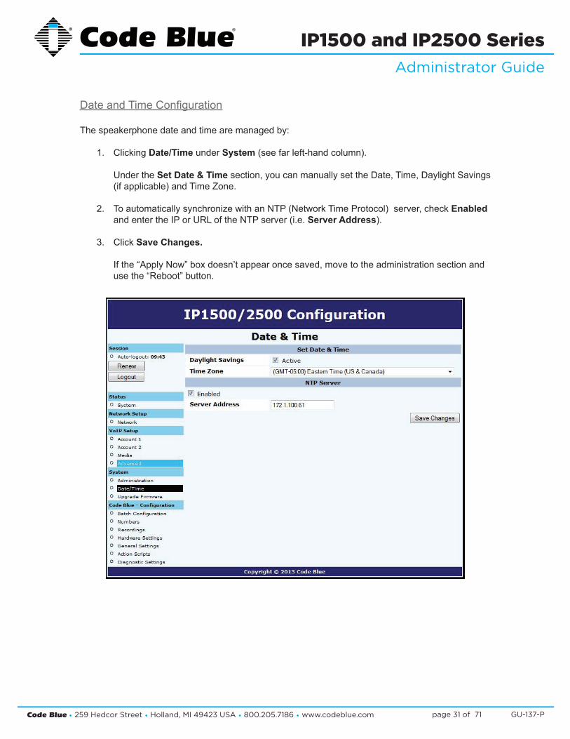
DateandTimeConfiguration
Thespeakerphonedateandtimearemanagedby:
1. Clicking Date/Time under System(seefarleft-handcolumn). Under the Set Date & Timesection,youcanmanuallysettheDate,Time,DaylightSavings (ifapplicable)andTimeZone.
2. ToautomaticallysynchronizewithanNTP(NetworkTimeProtocol)server,checkEnabled andentertheIPorURLoftheNTPserver(i.e.Server Address).
3. Click Save Changes. Ifthe“ApplyNow”boxdoesn’tappearoncesaved,movetotheadministrationsectionand usethe“Reboot”button.

Code Blue • 259 Hedcor Street • Holland, MI 49423 USA • 800.205.7186 • www.codeblue.com GU-137-Ppage 32 of 71
IP1500 and IP2500 SeriesAdministrator Guide
UpgradingtheIP1500/2500Firmware
Thespeakerphonefirmwarefilecanbechangedby:
1. Select Upgrade Firmware under System (seefarlefthandcolumn).
2. Click Browse(orSelect File)andselecttheappropriatefirmwarefile.
3. Click the Upgrade button.
4. Thespeakerphonewillupdate,automaticallybackupthenewfirmwareand reboot.Oncethisiscomplete,yournewfirmwarewillbeinuseandshouldbedisplayed nexttoCurrent Version.
Note:FirmwareversionisalsoreportedintheAdministration section.

Code Blue • 259 Hedcor Street • Holland, MI 49423 USA • 800.205.7186 • www.codeblue.com GU-137-Ppage 33 of 71
IP1500 and IP2500 SeriesAdministrator Guide
6.5 Configuring System Options and Scripts
Thespeakerphonehasadvancedconfigurationsettings,whichallowforcompletecontrolofthehardwareandhowthesystemperforms.Amemorycapacityof1MBprovidesformultiplephonenumberandrecordedmessagecapabilities.Incomingcallrouting,SNMPandadvanceddiagnosticsenhancedwithadvancedscriptingcapabilitiesprovideforflexibleconfigurations.
BatchConfiguration
ThespeakerphonecanbeconfiguredfromaTFTPserver,e.g.UPD.
1. Click on Batch Configuration under Code Blue(seefarleft-handcolumn).
2. Enter the TFTP Server IP address and TFTP Server Port.
3. Click on Fetch ConfigurationtopulltheconfigurationfilesfromyourTFTPserver.
4. Click on Verify Integritytovalidatetheconfigurationfilesaresuitableforuse. Ifyouarenotofferedthechangeto“ApplyNow”,movetotheAdministrationdialogand manuallyclickonthe“Reboot”button.
ThisfunctionalitycanbeusedinlieuofUPD’sprogramfunctionalitytohavethespeakerphonepullitsconfigurationinsteadofhavingitpushedfromUPD.
Code Blue • 259 Hedcor Street • Holland, MI 49423 USA • 800.205.7186 • www.codeblue.com GU-137-Ppage 34 of 71
IP1500 and IP2500 SeriesAdministrator Guide
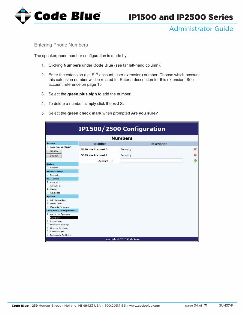
Entering Phone Numbers
Thespeakerphonenumberconfigurationismadeby:
1. Clicking Numbers under Code Blue(seefarleft-handcolumn).
2. Entertheextension(i.e.SIPaccount,userextension)number.Choosewhichaccount thisextensionnumberwillberelatedto.Enteradescriptionforthisextension.See accountreferenceonpage15.
3. Select the green plus sign to add the number.
4. Todeleteanumber,simplyclickthered X.
5. Select the green check markwhenpromptedAre you sure?

Code Blue • 259 Hedcor Street • Holland, MI 49423 USA • 800.205.7186 • www.codeblue.com GU-137-Ppage 35 of 71
IP1500 and IP2500 SeriesAdministrator Guide
Recordings Administration
Thespeakerphonerecordingconfigurationismadeby:
1. Selecting Recordings under Code Blue(seefarleft-handcolumn).
2. Click on Select recording fileandchoosethefileyouwishtouploadtothespeakerphone. Click Open.
3. EntertheDescriptionwithintheDescriptionField.
4. Click on the green plus signtoaddtherecordingandwaitforittofinish. DuringtheuploadprocessthescreenwilldisplayUploading file… Atthispointdonotrefreshthepageorclickawayfromthepageorthefilewillnotbe uploaded.OncethefileuploadiscompleteyouwillseeDownload Recording and a new lineforuploadingadditionalrecordings.
5. Todeleteanumber,simplyclickthered X.
6. Select the green check markwhenpromptedAre you sure.
Thespeakerphonesupportsthefollowingformatsandallfilesmustcontainmono(singlechannel)data.
• FilecontainingrawPCMuLawdata(extension.ulaw)• Wavefilecontainingmono8KHzor16KHzLinearPCMdata(extension.wav)
Note:Audiofileswillconsumememoryspacewithinthe1MBsharedmemoryallocation.

Code Blue • 259 Hedcor Street • Holland, MI 49423 USA • 800.205.7186 • www.codeblue.com GU-137-Ppage 36 of 71
IP1500 and IP2500 SeriesAdministrator Guide
HardwareSettings
Thespeakerphonehardwaresettingsareconfiguredby:
1. Selecting Hardware Settings under Code Blue(seefarleft-handcolumn).
2. SelecttheappropriateButton Count, Keypad Available settings under the Interface section.
3. CheckingAuxOutput1willenabletheauxoutputrelay.Bydefault,theportissettoenable (ToggleState)whenusedinanActionScript. When Momentary togglechoicehasbeenselected,thecalledpartynowhastheability toactivatetheauxoutputremotelyforthetimeperiodchosenviaDTMFtonesfromtheir phoneskeypad. Note: Momentary toggleisintendedforremotecontrolusebythecalledparty.It’s importanttounderstandthatscripteduseoftheauxoutputnotbeusedonanyauxoutput portthathasbeenselectedtoactinthemomentary(remotecontrolaspect)togglefunction. Also it is not recommended to use the General Settings > Incoming Calls > Aux Output 1 Enable on Incoming Callcheckbox.
4. Withselectionsmade,clickSave Changes.

Code Blue • 259 Hedcor Street • Holland, MI 49423 USA • 800.205.7186 • www.codeblue.com GU-137-Ppage 37 of 71
IP1500 and IP2500 SeriesAdministrator Guide
GeneralSettings
TheIP1500/2500speakerphonegeneralconfigurationcanbeaccessedby:
1. Clicking on General Settings under Code Blue(seefarleft-handcolumn).
2. Inthissectionyoucanselecthowmanyringsthespeakerphonewillwaitbeforeanswering an incoming call.
3. ClickthedownarrownexttoAnswerIntochangesettings.
4. The Aux Output 1checkbox,whenchecked,willenabletheAux Output 1 on incoming call and is disabled when incoming call is terminated. This feature was not intended to be used with Aux Outputsconfiguredwiththe momentarily toggle (Hardware Settings Dialog) choice.
Thespeakerphonecanalsobeconfiguredwithastandardlocationmessage.
1. Click on the down arrownexttoLocation Recording to select this recording as the default Location Message.
» Thelocationmessagemustbeuploadedbeforethischoicecanbemade.SeeRecording’s dialog.
2. Onceyouhaveconfiguredtheoptionsonthispage,clickSave Changes.

Code Blue • 259 Hedcor Street • Holland, MI 49423 USA • 800.205.7186 • www.codeblue.com GU-137-Ppage 38 of 71
IP1500 and IP2500 SeriesAdministrator Guide
ActionScriptConfiguration
ActionScriptsarebasedonHardwareSettingsmadeearlierinthesetupprocess.Forexample,ifyourspeakerphonehastwophysicalbuttonsandonlyonebuttonwasselectedinHardware Set-tings “Interface” “Button Count”somescriptschoiceswillbemissing.
Scripting RequirementsTheActionScriptinthespeakerphonecanbeveryextensive,yetonlyifallthecorrectfeaturesareenabled.Understandingalltheabilitiesofthephoneisrequired,onlythencantheuserconfigurethespeakerphoneformaximumfunctionality.
NumbersLoadphonenumbersforallofyourplannedcallsfromthisspeakerphone.
RecordingsRecordallmessageanduploadthemtothisspeakerphone.
Hardware SettingsEnsurethespeakerphonefeaturesarerepresentedintheHardwareSettingsportionoftheGUI.
Diagnostic SettingsWhenusingremotemonitoringservices,forexampleSNMPServerserviceorCodeBlue’sToolVoxServerw/UPDapplication,thespeakerphonewillsendSNMPtrapsorusethe“ActionScripts”togeneratecallstoamonitoringserviceandplaypre-recordedmessagesasanotificationanissuehas been detected.
SCRIPTING BASIC CALL
ThespeakerphonehasGUIinterfaceforbuildingscripts.ScriptingcanconsistofasingleactionorcombinationofactionsrelatedtoabuttonpressorAuxiliaryOutputTriggeralone.
• Click on Action Scripts under Code Blue(seefarleft-handcolumn)toprogramtheactionscriptsyouwishtheunittoperformduringbuttonactiva-tion or diagnostic condition.
• Toprogram,selectaButton or Diagnostic condition from theoptionlistbyclickingonthe down arrow across from Scriptfor:Forthisexampleselect Button #1 Pressed.
• Click on Add Action.
(Continued on next page)

Code Blue • 259 Hedcor Street • Holland, MI 49423 USA • 800.205.7186 • www.codeblue.com GU-137-Ppage 39 of 71
IP1500 and IP2500 SeriesAdministrator Guide
SCRIPTING BASIC CALL (continued)
• From the Select Actiondropdown,choosePlace Call.
• Bydefault,thefirstnumberplacedinmem-orywillbepresenthere.Ifanothernumberisdesired,usethedrop-downarrowtolocateandselectanotherphonenumber.
• Click on the Save Script button. This completesthebasicprogrammingneededtoplaceacall.
Other Basic Script ChoicesScriptinginthespeakerphoneallowsfornon-phonecallscriptingtobeprogrammedtomeetuniqueneeds of the customer.
1. Forexample,use“Button #1 Pressed”asseenintheexample“Basic Call”.
2. Instead of choosing “Place Call,” select “Control Aux Output”.
3. Bydefault,theAuxiliary1ispresented (butnoteonlythoseAuxOutputs selectedinHardwareSettingswillbe availableinthislist).
(Continued on next page)

Code Blue • 259 Hedcor Street • Holland, MI 49423 USA • 800.205.7186 • www.codeblue.com GU-137-Ppage 40 of 71
IP1500 and IP2500 SeriesAdministrator Guide
SCRIPTING BASIC CALL (continued)
4. NextchoiceistoEnablethisAuxOutputand/orsettheDuration for this Aux Output Action.Inthisexample,requesta10-seconddurationuponthetouchofbutton1.
5. NextclickonSave Script. Thisscriptisnowreadytobetested.TouchButton1totest.
Combining Multiple Actions in One “Script -- Advance Programming”Thefollowingexamplewouldbethemostcommonconfigurationdeployed.
1. Using Action Scripts > Script for:“Button#1Pressed”. Addthefollowingasseenintheexample: A.ControlAuxOutput–Enable B.PlaceCall–withmessagesforCallingpartyandCalledParty C.ControlAuxOutput–Disable
2. TheScriptshouldlooklikethis: Click Save Script whenfinished.

Code Blue • 259 Hedcor Street • Holland, MI 49423 USA • 800.205.7186 • www.codeblue.com GU-137-Ppage 41 of 71
IP1500 and IP2500 SeriesAdministrator Guide
ACTION SCRIPT PARAMETERS
WithintheScriptsaremanysettingscontrollingthenextstepintheprocessoftheActionScript:Du-rationoftheprocess,Enable/Disablefeatures,orevenareactivationofanAuxOutputwithatimedlimitation.ThefollowingwillprovidedetailedexplanationsintotheseScriptcontrols.
Note:Scripts,PhoneNumbersandRecordingsallsharea1Mbmemorycap.
Playing a Message MessagescanbesettoplayanytimeupontheactivationofaScriptorduringacall.
Plus,theycanbesettorepeatasshownhere:
Place Call Placing a Calliswheretheadministratorsetsupwhichnumberswillbeattemptedandtheorder.Theadministratorcouldchoosemultiplenumbersstoredin“Numbers”orthesamenumbercanberepeatedmanytimes.“Ifnotanswered,then”Call.Selectadditionalnumberstobedialed.
Dialing/Answer Timeout:Thedefaulttimeis60secondsandcanbesteppeddowntoaslittleasfiveseconds,beforethecallattempttimesout.
Maximum Call Duration: Thedefaulttimeis600seconds(10minutes).Durationrange0001to9999seconds(1secondupto166.65minutes).Thirtysecondsbeforethetimerexhaustsanaudibletonewillplaytonotifybothpartiesthecallisabouttoterminate,unlessthetimerisdisabledthroughaDuringcallCommand(DTMFtone3).
While Dialing:StandardRingbackisthedefaultsetting.Otherchoices:AmessagecanbesettoplaytothepersonattheIP1500/2500and/orDoNothing,untilthecallisconnected.
(Continued on next page)

Code Blue • 259 Hedcor Street • Holland, MI 49423 USA • 800.205.7186 • www.codeblue.com GU-137-Ppage 42 of 71
IP1500 and IP2500 SeriesAdministrator Guide
ACTION SCRIPT PARAMETERS (continued)
Place Call(continued)When Answered: The default setting is Normal Two-Way Conversation, the optionistoPlay Custom Messages. A messagecanbesettoplayLocally(atthespeakerphone)and/orRemotely(tothe Called Party).
ChoosingthisoptionwilladdanotheroptiontothePlacecallsequence,And Then.The And Then choice allows the call to continue through to normal two-way conversationmodeorHang Up and resetthespeakerphone.
Note:Inthisfeature,itisprohibitedtousethesameexactmessageinbothlocalandremotelyse-lection.
In Call Commands: The default is Enabled. All Remote Control DTMF tone commands areavailableforusebythecalledparty.ThealternatechoiceisDisabled,effectivelylockingout all DTMF tone commands from the Called Parties control. Control AUX Output
• AuxOutputscanbeactivatedanddeactivatedthroughoutaScript.
• AuxOutputscanalsobesettoactivateonincomingansweredcalls.
• ItisstronglyadvisedthatwhenthisfeatureisusednootherconfigurationsareenabledforanAuxOutputwithMomentaryToggleselectedinHardware Settings.

Code Blue • 259 Hedcor Street • Holland, MI 49423 USA • 800.205.7186 • www.codeblue.com GU-137-Ppage 43 of 71
IP1500 and IP2500 SeriesAdministrator Guide
SampleApplicationusingDualAccountsontheIP1500/2500Phone
Ifusingbothaccountsonaspeakerphone,youmustthensetup2numbers(one“via Account 1” and the other “via Account 2”),andanactionscriptwithasingledialstepwith“call first number” and “if not answered then call second number”.
Useoutcomesdependentonthenetwork:
1. Ifserver1isconsideredregisteredandresponds,thecallgoesthroughtoserver 1 immediately.
2. Ifserver1isconsideredregisteredandunresponsive,itwillbe tried for the time listed in Dialing/Answer timeout,butnomorethan30seconds;then server2willbetried.
3. Ifserver1isnotconsideredregistered,server1willbeskipped andserver2willbetriedimmediately.

Code Blue • 259 Hedcor Street • Holland, MI 49423 USA • 800.205.7186 • www.codeblue.com GU-137-Ppage 44 of 71
IP1500 and IP2500 SeriesAdministrator Guide
AuxiliaryOutputExpandedFunctionality&UseCase
Thespeakerphonev2AuxOutputabilitieshasbeenexpandedforuniqueusecases:SecurityPer-sonal Access Control.
Example:
Gate or Door ControlEitheroutputcanbeconfiguredtoactivateuponthecalledpartiesuseoftheDTMFkeys4or5onHisorHerphone,forapredeterminedtimeperiodneededbytheGateMechanism(example-4seconds).
SettingupAuxiliaryOutput1toMomentarilyTogglefor4seconds.
Aux Output Momentary Toggle is best used for remote control operations and should not be com-bined with Scripted Timed Aux Output timers or Incoming Calls > Aux Output > Enable when an Incoming Call is active.

Code Blue • 259 Hedcor Street • Holland, MI 49423 USA • 800.205.7186 • www.codeblue.com GU-137-Ppage 45 of 71
IP1500 and IP2500 SeriesAdministrator Guide
ConfiguringDiagnostics
Diagnostic SettingsThespeakerphonediagnosticsettingsareconfiguredby:
• Selecting Diagnostic Settings in the Code Blue Configuration.
• Click the Enablecheckbox.
• InputtheSNMP Server IP address and SNMP Server Port number to monitorthespeakerphonewithanSNMP management software or with CodeBlue’sToolVoxGateway,withUnitProgramming&Diagnostic(UPD)Software.
• PoEPowerFailure:PoEpoweristhesolepowersourceandifaninterruptioninserviceisexpe-rienced,noTrapwillbesentduetolossofPoEenergy.ThePoEswitchshouldalertyoutoPoEswitch state.
Others – (Tests)Microphonetestingisdisabledbydefault,andenablingwillshowanumberofreoccurringtestroutines.Themicrophoneissupportedbythespeaker’sabilitytogeneratetonesatthescheduleintervals.
• Thetestconsistsofbeepsfromthespeaker,whichwillbereceivedbythemicrophone. The maximum number of beeps: 10 beeps Oncethemicrophonedetectsthebeeps,thetestiscompleteuntilthenextscheduledtestis present. The beep tone volume choices are soft, loud, or soft to loud. Beeptonevolumesettingshouldbesettoanticipateambientnoiselevelatthetimeofthe test.
• The test schedule choices are: Every15minutes Hourly Daily Weekly
Testingondemand:Whenmicrophonespeakertestingisenabled,theadministratormayselecttoRun Test whileloggedintothespeakerphone.TheresultsofthetestwillonlybepresentinafailedSNMPtrap,whichwouldappearintheSNMPserverlogsorUPDDiagnosticReportslogs.TheMIBvalueisCODEBLUE-MIB::micSpeakerFailure.

Code Blue • 259 Hedcor Street • Holland, MI 49423 USA • 800.205.7186 • www.codeblue.com GU-137-Ppage 46 of 71
IP1500 and IP2500 SeriesAdministrator Guide
7 CLI (Command Line Interface) Thespeakerphonehasextensivecommandsthatcanbeusedbytelnettingintothedevice.Youcanusewindowstelnetordownloadacommonfreetelnetclient,“putty”.TelnettotheIPAddressofthespeakerphone:useport23ifunsure.
LoginisthesameasthroughtheWebGUI. admin admin
Youcantype“help”toseealistofavailablecommands.The most commonly used:
Format c: codeblue–Usingthiscommand,youformatthephoneandreturnittofactory default.Thiscommandmustthenbefollowedupwithareboot.
Reboot–Makethephonereboot.
Ping IP Address or Domain Name–PingtheIPPBXtoseeifthephonecanreachits registrar.
Button 1 –Selectbutton1-4andinitiateabuttonpushremotely.Thisisveryhandyforre- motetesting.Button1istheredbutton.Button2istheblackbuttonifequipped.

Code Blue • 259 Hedcor Street • Holland, MI 49423 USA • 800.205.7186 • www.codeblue.com GU-137-Ppage 47 of 71
IP1500 and IP2500 SeriesAdministrator Guide
8 In-Call Commands ThespeakerphoneprovidesenhancedfunctionalitythroughtheutilizationofInCallCommands.ThesecommandsareDTMForphonekeypadentriesmadebytheCalledparty.Belowisalistandexplanationofeachcommand.
In-Call Command Function Description1 Play Location Message Plays the Location Recordings selected in
GeneralSettings3 DeactivateCallTimer DeactivatestheMaximumcalldurationtimer
settingintheoperationalscriptcurrentlyrunning
4 Activate/DeactivateAuxiliary1 ToggleAuxiliary1state;activateordeactivate
6 MicVolumeUp Increasethemicrophonegain;usedtoincreasetheCalledpartyvolume
7 MicVolumeDown Decreasethemicrophonegain;usedtodecreasetheCalledpartyvolume
8 SpeakerVolumeUp Increasethespeakervolume;usedtoincreasetheCallingpartyvolume
9 SpeakerVolumeDown Decreasethespeakervolume;usedtodecreasetheCallingpartyvolume
Note:SomeVoIPcodecsdonotfullysupportDTMFTonesignallyandmaynotfunctionasintended.

Code Blue • 259 Hedcor Street • Holland, MI 49423 USA • 800.205.7186 • www.codeblue.com GU-137-Ppage 48 of 71
IP1500 and IP2500 SeriesAdministrator Guide
9 Factory Reset Thesystemcanberesetviatwodifferentmethods.
1st Method:
Thespeakerphonecanberesetbyfollowingthestepsbelow:Usethe7pinresetplug(sentwithyourorder)inordertoperformafullreset. 4&5LongReset=HardReset,setseverythingbacktodefault2&3ShortReset=Resetsnetworkconfiguration
• UnplugtheRJ45fromthePoEswitchport• UnplugbuttonanddisconnecttheLEDharness• Shorttheappropriate2pinstogetherforshortorlongreset(seepicbelow)• PlugtheRJ45backintothePoEswitchport• Uponhearingtwoshortbeeps,unithasbeenreset• Wait10secondsforphonetoreboot• Unplugpowersource• Removethejumperandreconnectthebuttons• Reconnect7pinharness• Reconnect PoE
TheResetisnowcomplete.
(Continued on next page)

Code Blue • 259 Hedcor Street • Holland, MI 49423 USA • 800.205.7186 • www.codeblue.com GU-137-Ppage 49 of 71
IP1500 and IP2500 SeriesAdministrator Guide
Factory Reset (continued)
2nd Method:
Ifyouhavetelnetaccesstotheunit,youcandefaulttheunitthroughthecommandline.
• Using Windows Telnet Open<IPAddress><port>
• Enter Username: admin and Password: admin• Attheprompt,typeformat c: codeblue• Aftersuccessfullyformattingthephone,type reboot
Code Blue Technical Support: 800-205-7186Technicalsupporthoursarefrom8a.m.to5p.m.,MondaythroughFridayEasternStandardTime

Code Blue • 259 Hedcor Street • Holland, MI 49423 USA • 800.205.7186 • www.codeblue.com GU-137-Ppage 50 of 71
IP1500 and IP2500 SeriesAdministrator Guide
10 Compatibility ThespeakerphoneisaSIPversion2.0(RFC3261)deviceandiscompatiblewithIPGatewaysandPBXsthatcanregisterthirdpartySIPdevicestothem.
YoumustverifythattheIPPBXyouareregisteringthespeakerphonetocanhandlethirdpartySIPdeviceswhetherthroughlicensingand/orHardwareadd-ons.
SomeexamplesofmainstreamIPPBXsthespeakerphonehasregisteredtoasathirdpartySIPdeviceare:
AsteriskCisco Call Manager
and many others…

Code Blue • 259 Hedcor Street • Holland, MI 49423 USA • 800.205.7186 • www.codeblue.com GU-137-Ppage 51 of 71
IP1500 and IP2500 SeriesAdministrator Guide
PREPARATION
1. Record the MAC address and determine the current IP address for each IP1500/2500/5000 deviceyouwishtousewithCUCM.
2. DeterminewhichpartitionyouwillputtheIP1500/2500/5000directorynumbersinto.
3. ObtainonedirectorynumberforeachIP1500/2500/5000device.
a. IfyouaregoingtousetheIP1500/2500/5000’sdualaccountconfigurationtoregis tertoredundantCUCMservers,obtainaseconddirectorynumberforeach IP1500/2500/5000device.
4. DeterminewhichcallingsearchspaceyouwillassigntotheIP1500/2500/5000.
IP5000 CONFIGURATION
RefertotheIP1500/2500/5000AdministrationANDUserGuidelocatedonourwebsite
Clear Existing Configuration
Ifnecessary,cleartheIP1500/2500/5000’sexistingconfiguration.ThiswillresetittoDHCP,somakesureyouhavethecapabilitytofindthedevice’sIPaddressagainifyoudothis.Foreachunit:
1. OpenaTelnetclientandconnecttotheIP1500/2500/5000.
2. Loginusingtheusernameadminandthedefaultpasswordadmin.
3. Typeformatc:codeblueandpressEnter.
4. TyperebootandpressEnter.
Configure Account(s)
1. LogintotheIP1500/2500/5000viaitswebinterface.Thedefaultusernameandpassword are admin and admin.
2. Select Account 1.
3. ForVoIPProtocol,selectSIP&RTP.
4. UnderSIPConfiguration,forUsername/Number,enterthedirectorynumberyouassigned earlier.
5. ForDisplayName,entercallerIDtext.
6. ForDomain,enterthehostnameorIPaddressoftheCUCMnodeyouwishtoregisterthis account to.
11 Configuring for Cisco Unified Communications Manager 9

Code Blue • 259 Hedcor Street • Holland, MI 49423 USA • 800.205.7186 • www.codeblue.com GU-137-Ppage 52 of 71
IP1500 and IP2500 SeriesAdministrator Guide
7. InsureKeep-Aliveisenabled.
8. UnderProxyAuthentication,forUsername,entertheusernameyouassignedtheCUCM enduser,e.g.thehexadecimalrepresentationoftheMACaddressorthelocal-usevariant for a secondary account.
9. ForPassword,enterthepasswordyouenteredintoDigestCredentialsundertheCUCM end user.
10. ClickSave.
11. Repeatsteps3-10withAccount2ifyouareusingthesecondaccount.
Other Settings
RefertotheIP1500/2500/5000AdministrationANDUserGuidetocompletethesetupoftheIP1500/2500/5000,includingNumbers,GeneralSettings,HardwareSettings,andActionScripts.Whenfinished,clickApplyNowtorestartthephone;itshouldnowregistertoCUCMandbeabletoplacecallsintheassignedcallingsearchspaceaswellasreceivecallsatthedirectorynumberitisconfiguredwith.
Note: if you are setting up the IP1500/2500/5000 with secondary account support, make sure that you create each failover number twice.
UCM CONFIGURATION
AllUCM-sideconfigurationisdonewithintheCiscoUnifiedCMAdministrationwebinterface.
Create Phone Security Profile
1. NavigatetoSystem>Security>PhoneSecurityProfile.
2. DoaFindon“Third-party”tolocatetheThird-partySIPDeviceBasic-StandardSIPNon- SecureProfile.ClicktheCopyicon.
3. Check Enable Digest Authentication.
4. ChangetheNameandDescriptiontoCodeBlueIP1500-2500-5000Profile.
5. ClickSave.
Configure End Users
ForeachIP5000device,configureanewenduserforSIPauthentication.
1. NavigatetoUserManagement>EndUser.
2. Click Add New.
3. FortheUserID,enterthehexadecimalversionoftheMACaddress;e.g.00:50:C2:17:7B:E8

Code Blue • 259 Hedcor Street • Holland, MI 49423 USA • 800.205.7186 • www.codeblue.com GU-137-Ppage 53 of 71
IP1500 and IP2500 SeriesAdministrator Guide
would become 0050c2177be8.
a. UseoftheMACaddressasuserIDisonlyarecommendation.Iflocalconfiguration permits,youcanuseanyotherformofuserID;justbesuretorecordwhichuserID goeswithwhichphoneandwhichofthephone’saccounts.
4. FillintheLastnamefieldwithadescriptionofthestation.
5. CreateandrecordasecureSIPpasswordandfillintheDigestCredentialsandConfirm DigestCredentialsfieldswiththispassword.Youwillbeenteringthispasswordlaterinto the IP1500/2500/5000.
6. ClickSave.
Configuring End Users for Secondary Accounts
If you are going to use the IP1500/2500/5000’s secondary account functionality to register to a separatedirectorynumbertoaseparateCUCMnodeforfailoversupport,repeattheaboveprocessusing a local-use-only MAC address. A local-use-only MAC address has the U/L bit set to 1 to indi-cate the address is locally administered.
SinceallIP1500/2500/5000units’MACaddressesstartwith0,youcancreatealocally-administeredaddressthatisunlikelytoconflictwithotherlocally-administeredaddressessimplybysettingtheU/Lbitsimplymeanschangingthesecond0toa2,e.g.0250c2177be8.
Configure Phones and Directory Numbers
ForeachIP5000device,configureanewPhoneandassociateddirectorynumber.
1. NavigatetoDevice>Phone.
2. Click Add New.
3. ForPhoneType,selectThird-partySIPDevice(Basic).
4. EntertheMACAddressofthephoneinhexadecimalformat;e.g.00:50:C2:17:7B:E8would become 0050c2177be8.
5. ForDevicePool,selectDefault(orsomeotherlocally-configureddevicepool).
6. ForPhoneButtonTemplate,selectThird-partySIPDevice(Basic).
7. ForCallingSearchSpace,selectthecallingsearchspacetheIP1500/2500istouse.
8. ForDeviceSecurityProfile,selectCodeBlueIP1500-2500-5000Profile.
9. ForSIPProfile,selectStandardSIPProfile.
10. ForDigestUser,selecttheendusermatchingtheMACaddressofthephone,orthealter nateuserIDyoucreatedwhenyouwereconfiguringtheenduser.

Code Blue • 259 Hedcor Street • Holland, MI 49423 USA • 800.205.7186 • www.codeblue.com GU-137-Ppage 54 of 71
IP1500 and IP2500 SeriesAdministrator Guide
11. ClickSave.
12. Ontheleftsideofthescreen,clickLine[1]-AddanewDN.
13. Fill in the Directory Number.
14. ForRoutePartition,selectthepartitionthedirectorynumberresidesin.
15. UnderLine1,forDisplay(InternalCallerID),enteradescriptivenameforCallerIDpur poses.
16. IfyouwishtoreturnabusysignalforsilentmonitoringiftheIP1500/2500/5000isinuse, disable Call Waiting:underMultipleCall/CallWaitingSettings,ForbothMaximumNumberofCallsand BusyTrigger,enter1.
17. ClickSave.
Configuring Phones and Directory Numbers for Secondary Accounts
IfyouaregoingtousetheIP1500/2500/5000’ssecondaryaccountfunctionality,repeattheaboveprocesswithalocal-use-onlyMACaddressasoutlinedinConfiguringEndUsersforSecondaryAc-counts,andspecifyadistinctdirectorynumber.
Integrating InformaCast Utilizing Cisco Call Manager
AccesstotheInformaCastemergencynotificationsystemproducedbySinglewireSoftwarefre-quentlyisincludedwithCiscoUnifiedCommunicationManager(CUCM).CodeBlue’sVoIPspeak-erphones(IP1500/2500/5000)canberegisteredandconfiguredwithCUCMasSIPdevicesthatarecompatiblewithIPGatewaysandPBXsthatcanregisterthird-partySIPdevices.RefertoSection10.4 of this guide for additional details.
TosendaudiopagesfromInformaCasttoCodeBluespeakerphones,selecttheCodeBluedevicesasendpointphonesforthemessages.TheCodeBluephoneswillhavetheabilitytoanswerandplaytheaudiobydefault.

Code Blue • 259 Hedcor Street • Holland, MI 49423 USA • 800.205.7186 • www.codeblue.com GU-137-Ppage 55 of 71
IP1500 and IP2500 SeriesAdministrator Guide
12 Avaya IP Office Integration Guide
Introduction
ThisAvayaIPOfficeIntegrationGuideprovidesgeneralinstructionsforintegrationoftheIP1500/2500/5000 Series PhoneswithanIPOfficeinstallation.Readthisinstructionsetcompletelybefore starting any installation. For detailed IP1500/2500/5000setupinstructions,pleaseconsulttheIP1500/2500/5000 Guides.
Prerequisites
• AvayaIPOfficeManagerVersion9pre-installed• SIPDeviceLicensingfor3rdPartyIPEndpoints• NetworkaccesstotheIPOfficeManager,IP1500/2500/5000 Series Phones and allnetworkservices(SIP,HTTP,FTP,RTP/SRTP)
IP Office Manager Basic Configuration
Basic instructions for integrating IP1500/2500/5000 Series PhoneswithanAvayaIPOfficeR7Managerareincluded.AdvancedsetupofIPOfficeManagerfeaturesisoutsidethescopeofthisdocument.
1. UsingIPOfficeR7Manager,connecttotheIPOfficeControlUnit.

Code Blue • 259 Hedcor Street • Holland, MI 49423 USA • 800.205.7186 • www.codeblue.com GU-137-Ppage 56 of 71
IP1500 and IP2500 SeriesAdministrator Guide
2. LogintoAvayaIPOfficeManager:
3. SIPExtensionSupportisrequiredforIP1500/2500/5000 integration. Select System > LAN1 (or LAN2) > VoIPinIPOfficeManager:

Code Blue • 259 Hedcor Street • Holland, MI 49423 USA • 800.205.7186 • www.codeblue.com GU-137-Ppage 57 of 71
IP1500 and IP2500 SeriesAdministrator Guide
4. Check that SIP Registrar Enable is enabled.
5. Select the SIP Registrar sub-tab.6. In Domain Name,entertheFullyQualifiedDomainName(FQDN)ortheIPad
dressassociatedwiththecorrectLANportontheIPOfficeControlUnit.Deselect Auto-create Extn/User. Click OK.

Code Blue • 259 Hedcor Street • Holland, MI 49423 USA • 800.205.7186 • www.codeblue.com GU-137-Ppage 58 of 71
IP1500 and IP2500 SeriesAdministrator Guide
7. ASIPextensionwillneedtobecreatedforeachIP1500/2500/5000 Series Phone. Right click on Extension,selectNew and then click on SIP Extension.
8. Enterthefollowingfieldstocreateanewextension: • Extension ID: AuniqueextensiontoidentifythelogicalextensioninIPOffice.By default,IPextensionsstartat8000. • Base Extension:ThisistheextensionusedtocalltheIP1500/2500/5000 Series Phone. • Force Authorization: Select to force authentication of the IP1500/2500/5000 Series Phone.

Code Blue • 259 Hedcor Street • Holland, MI 49423 USA • 800.205.7186 • www.codeblue.com GU-137-Ppage 59 of 71
IP1500 and IP2500 SeriesAdministrator Guide
9. Select the VoIP tab and select the Compression Mode. The default of the IP1500/2500/5000 Series Phone is G.711 U-LAW and will work in most cases. More information on audio codecs can be found in the IP1500/2500/5000 Series Phone Guides. Set DTMF Support to RFC2833.
10. Each IP1500/2500/5000 Series PhoneshouldhaveauniqueUser.Rightclick on User and select New.

Code Blue • 259 Hedcor Street • Holland, MI 49423 USA • 800.205.7186 • www.codeblue.com GU-137-Ppage 60 of 71
IP1500 and IP2500 SeriesAdministrator Guide
11. Enterthefollowingfieldstocreateanewuser; • Name: Thiswillbedisplayedastheuser’snameinIPOfficeManager,andis usedastheusernameforSIPregistrationwhenconfiguringthe IP1500/2500/5000 Series Phone. • Extension: This should match the Base ExtensionconfiguredfortheSIPexten- sioninStep8.Thisisalsousedasthephonenumberwhenconfiguringthe IP1500/2500/5000 Series Phone.
12. Select the Telephony tab and then the Call Settings sub-tab. Disable Call Waiting On and Answer Call Waiting on Hold.Callwaitingisnotsupportedon the IP1500/2500/5000 Series Phone.

Code Blue • 259 Hedcor Street • Holland, MI 49423 USA • 800.205.7186 • www.codeblue.com GU-137-Ppage 61 of 71
IP1500 and IP2500 SeriesAdministrator Guide
13. Select the Supervisor sub-tab. In the Login Codefieldenterapasswordtobe used by the IP1500/2500/5000 Series Phoneforauthentication.AvayaIPOffice willonlyacceptnumbersinthisfield.
14. IfaddingmultipleIP1500/2500/5000 Series Phones,repeatSteps7-13foreach device.

Code Blue • 259 Hedcor Street • Holland, MI 49423 USA • 800.205.7186 • www.codeblue.com GU-137-Ppage 62 of 71
IP1500 and IP2500 SeriesAdministrator Guide
Thespeakerphonecanbeconfiguredformultipleuses.Themainfunctionistoprovide2-wayvoicecommunications.Pressingtheredbuttonwillactivatetheconfiguredscriptprogrammedforbutton#1.
Button#1activationoverridesanyotheractionthespeakerphoneisperformingatthetimeofthebuttonpress.Forexampleifthespeakerphone:
1. Isbeingprogrammedatthetime2. Was in a monitoring call3. Was in the middle of a diagnostic test4. Iscurrentlyinaninformation(button#2)call.
Button#2, INFO or CALLbuttonsaretypicallyutilizedforplacinginformationalcalls.AnyactionotherthanButton#1activationisconsiderNon-Prioritycallingandcommonlyutilizedfordirectorservice,student/employeeescortrequests,gateentry,guestservicesandsimilarrequests.
Thespeakerphone’sAuxiliaryOutputistypicallyutilizedforactivatingCodeBlue’sLEDBeacon/Strobe,andcanbeusedasanormallyopen(N.O.)drycontactclosure(seespecforrelayratings)used,forexample,toactivatecentralizedbuilding/securitymanagementequipment.
Incomingcalls:Thespeakerphoneauto-answersanincomingcall.(Basedonthesettingsconfig-ured under General Settings in General Configuration > Incoming Calls > Answer in Immedi-atelyorafteranumberofrings.)
13 Using the IP1500 and IP2500 Series Speakerphones

Code Blue • 259 Hedcor Street • Holland, MI 49423 USA • 800.205.7186 • www.codeblue.com GU-137-Ppage 63 of 71
IP1500 and IP2500 SeriesAdministrator Guide
14 Button and Activation Specifications
Thebuttonrequiresaforceof3-5N(Newton-siunits).Anotherwaytoexplainthis:6–18ozofpressureovertimeapplied,whichisbetween125–300ms(0.15–0.3seconds).
Slappingorslidingyourfingersacrossthebuttonwillnotactivateit.Itrequirespressureovertime.Theouteredgeofthebuttonwillnotbethatsensitive.Normaluseofthebuttonwouldbesomeonerushingtoactivateitandusingtheirhand,finger,arm,knee,forehead,etc. Nootherpiezoelectricbuttononthemarketwillfunctionaswell.
TheonlydifferencesbetweentheanalogandIPbuttonsaretheoutputonthewiresandthestateofthebutton,N.OorN.C.Thebuttoncanandpiezoelementsareidentical.Theanalogbutton(2wire)isN.O.(NormallyOpen),andclosesmomentarilywhenpressed.Thedigitalbutton(3wire)isN.C.(NormallyClosed)andwhenpressedthestategoestoopenmomentarily,whichistranslatedtoaPthenRdataoutputtotheIP1500/IP2500/IP5000 boards.
Thespecificationofthebuttonis:
Switching Current: 0.200 A
Actuation Force:3-5N:6–18ozofpressureovertimeapplied.Whichisbetween125–300ms(0.15–0.3seconds)
Make Impulse Time: 125-300 mSEC
Switch Resistance : “ON”<20ohms
Switch Resistance: “OFF”>5MOhms
Make Pulse Time: 125-300 mSEC
Surface Deflection: 1micron-activation
Button Temperature : -40°Cto+85°C(-40°Fto185°F)
Functional Life: >50millionactivations
Functional in Freezing Rain: Yes

Code Blue • 259 Hedcor Street • Holland, MI 49423 USA • 800.205.7186 • www.codeblue.com GU-137-Ppage 64 of 71
IP1500 and IP2500 SeriesAdministrator Guide
15 Speaker Specifications
SPL Level Test ResultsMeter used: EXTECH InstrumentsModel 407732
Mode dBASettings:FAST&Hi(Hi=65~130dB)TonewasgeneratedwithinAsteriskandassignedtoextensionnumber.
Thephonewasprogrammedtodialtheassignednumberforthefrequencyofchoice,whichcreatedasignaltobeplayedthroughthespeakerofthephone.
Tone (Hz) IP1500 2” spkr IP2500 3.5” spkr1000 92.9dBA 96.0dBA2000 96.0dBA 100.0 dBA5000 99.4dBA 101.1 dBA
EXTECH meter was placed exactly one meter from the speaker on the same plane.Each tone was played for three seconds, and the MAX reading was logged.

Code Blue • 259 Hedcor Street • Holland, MI 49423 USA • 800.205.7186 • www.codeblue.com GU-137-Ppage 65 of 71
IP1500 and IP2500 SeriesAdministrator Guide
16 Remote Mount Beacon/Strobe Installation
1.0 ATTACH J-BOX TO THE POLE
1.1 Threadthebanding(B)throughthepolebracket(A)locatedonthebacksideoftheJ-box(C).
1.2 Wrapthebandingaroundthepole.Cutthebandingtodesiredlength.
1.3 Usingascrewdriverornutdriver,tightenthebandingandmakesurethattheunitisinthedesired location.
NOTE:J-boxmustbepositionedsoweepholefacesdown.
2.0 ATTACH LIGHT TO BRACKET
3.1 UsingthethreeM4X8screwsenclosed(K),fastenthestrobe(J)totheroundportionofthestrobe bracket.
NOTE: If the beacon/strobe is mounted upside-down, a drain hole must be drilled into the lens to prevent it from filling with water.
3.0 ATTACH LIGHT AND BRACKET TO THE J-BOX
4.1 ConnectallwiringfromthestrobetothewiringfromtheunitinsideoftheJ-boxusingwirenuts.
4.2 AttachstrobebrackettotheJ-boxusingfour6-32X½screwsasshown.
Allwiringmustbeinstalledandconnectedbyexperiencedandcertifiedpersonneltomeetlocalandnationalelectricalcodes,andwillincludeaservicedisconnect.
A - pole-bracketB - banding C - J-boxD - pole-bracketmountnut(4each)E - pole-bracketmountscrew(4each)F - conduitplugH - strobe-bracketI - 6-32X½screws(4each)J - strobe lightK - M4X8screws(3each)(Lowvoltage)K - 10-24X¾screws(2each)(Highvoltage)

Code Blue • 259 Hedcor Street • Holland, MI 49423 USA • 800.205.7186 • www.codeblue.com GU-137-Ppage 66 of 71
IP1500 and IP2500 SeriesAdministrator Guide
17 Troubleshooting
TROUBLESHOOTING THE IP1500 AND IP2500 SERIES SPEAKERPHONEThespeakerphoneisanetworkdevice.Thefollowingaretipsfortroubleshooting:
Power -Ensurethepowertoyourdeviceisworkingandratedfor802.11afPoEspecifications.
Ping Test -Thisdeterminesconnectivityandthepacketlossandlatencytimetoandfromyourdestinationandthequalityofyournetworkconnectiontoyourspeakerphone.IfyoureceivenoresponseandPoEpowerisconfirmed,contactyournetworkadministrator.YoucanalsoPingfromwithinthephonetowardsyourIPPBXtotestthatitcanreachitsregistrar.SeeCLICommands.
DHCP -ThespeakerphoneissetupforDHCPbydefault.IfyoucannotdeterminetheIPaddressofyourspeakerphone,contactyournetworkadministrator.
Account -EnsureyourSIPorIAX2accountissetupcorrectly.AccountusernameandpasswordmustmatchtheaccountcredentialsonyourVoIPsystem.ThisisthemostcommonmistakewithsettingupSIPaccounts.
Codec -EnsureyourcodecsettingsonyourVoIPsystemmatchtheIPspeakerphonecodecset-tings.
Firewall -FirewallscommonlyblockorpartiallyblockVoIPcalls.Checkwithyournetworkadminis-tratorifyoucannotcommunicatewithyourspeakerphonefrombehindafirewall.
ContactinformationforCodeBlue’sTechnicalServicesandSupportstaffcanbelocatedattheendofthisGuideifyouneedfurtherassistancetroubleshootingyourspeakerphone.Dependingonyourissue,afirmwareupgrademaybeneeded.
Note:IfyoudonothaveaDHCPserverrunning,useastandardhome/wirelessrouterandplugyourspeakerphoneandlaptopintothesamerouter.OnceyouknowtheIPAddress,youcanbrowsetoitviayourwebbrowser.

Code Blue • 259 Hedcor Street • Holland, MI 49423 USA • 800.205.7186 • www.codeblue.com GU-137-Ppage 67 of 71
IP1500 and IP2500 SeriesAdministrator Guide
18 Technical Specifications
• Fullduplexspeakerphone,intercomandpagingdevice
• 1MBmemorystorageforphonenumbersand audio messages
• Phonenumbersupto255digitslong• SIP/IAX2Protocolsupport• STUNclientforNATtransversal• UDP,TCPandTLS• 1xIEEE802.310/100Ethernetport• Embeddedwebserver• Security includes:
» HTTPS » TransportLayerSecurity(TLS) » SRTP(RFC3711),SIPS » RTCP » VLAN » Passwordprotection
• DTMFinband/outofband/INFO• 1xHybridpressuresensitivedatabutton inputs
• 1xauxiliaryN.O.outputcontactclosureswithprogrammabletimingcapability
• Self-monitoringandfaultreporting: » Communicationservice » Button failure » Speakerfailure » Microphonefailure
• MessagePlaybackoptions: » Multipleandrepeatingduringcallplaced
» Multipleandrepeatingduringcallreceived
» MessageplaybackduringacallviaDTMF commands
• In-CallcommandsviaDTMF:
Power Features PoweroverEthernetIEEE802.3af/atCommunications IP CommunicationsEnvironmental -40°Cto70°C(-40°Fto158°F) 0%-95%RHNon-condensingStandard Features
» Auxiliaryoutputcontrol » Incremental increase/decrease speaker,microphone
» Messageplayback• Built-inscriptinglanguageprovidesadvancedbuttonanddiagnosticreportprogramming
• Corrosion resistant connectors• Enhancedspeakerphoneandmicrophonesensitivity
• Non-volatilememoryensuresprogram-mingisretainedduringpowerloss
• ConformalcoatedPCBsforenvironmen-talprotectionandoperation
• ADAcompliantwithBraillesignageandLED indicators
• ToolVoxMediaGatewayemailsfaultsta-tusreportaboutphone
• NEMA 4/IP 55 rated• Dual account registration for redundancy• BuiltwithpowerfulDSPtechnology
For IP1500 Only
» StandardBezelOptions » StandardSurfaceMountHousingColor: Safety Blue
» StandardFlushMountFaceplateColor: Stainless
For IP2500 Only » TwohighlyvisibleLEDindicatorsforADAcomplianceforhearingimpaired
» Optionaldualbuttonfaceplate

Code Blue • 259 Hedcor Street • Holland, MI 49423 USA • 800.205.7186 • www.codeblue.com GU-137-Ppage 68 of 71
IP1500 and IP2500 SeriesAdministrator Guide
19 RegulatoryTheIP1500andIP2500Seriesspeakerphonesconformtothefollowinglistofdirectivesandproductsafetystandardsasapplicable:
EU: EN 55022:2006+A1:2007EN 55024:1998+A1:2001+A2:2003EN 61000-4-2:1995EN 61000-4-3:2006+A1:2008EN 61000-4-4:2004EN 61000-4-5:2006EN 61000-4-6:2007EN 61000-4-8:1993+A1:2001EN 61000-4-11:2004EN 61000-3-2:2006+A1:2007EN 61000-3-3:2008
USA: CFR 47, Part 15CANADA: ICES-003e
17.1 ETL Required Labeling
TheIP1500andIP2500SeriesoffullduplexVoIPspeakerphonesarelabeledinaccordancewiththe UL 2017 standard.

Code Blue • 259 Hedcor Street • Holland, MI 49423 USA • 800.205.7186 • www.codeblue.com GU-137-Ppage 69 of 71
IP1500 and IP2500 SeriesAdministrator Guide
20 WarrantyCodeBlueCorporationprovidesalimitedwarrantyonthisproduct.Refertoyoursalesagreementtoestablishtheterms.Inaddition,CodeBlue’sstandardwarrantylanguage,aswellasinformationregardingsupportforthisproductwhileunderwarranty,isavailableatwww.codeblue.com/support.
Notice:Everyeffortwasmadetoensurethattheinformationinthisdocumentwascompleteandaccurateatthetimeofprinting.Informationissubjecttochange.

Code Blue • 259 Hedcor Street • Holland, MI 49423 USA • 800.205.7186 • www.codeblue.com GU-137-Ppage 70 of 71
IP1500 and IP2500 SeriesAdministrator Guide
21 Technical Services and Support Foradditionalsupport,pleasefeelfreetocontactCodeBlue’sTechnicalServicesandSupportStaffat [email protected] or (800) 205-7186, Opt 3.
8 a.m. to 5 p.m. Monday through Friday Eastern Time

Code Blue • 259 Hedcor Street • Holland, MI 49423 USA • 800.205.7186 • www.codeblue.com GU-137-Ppage 71 of 71
IP1500 and IP2500 SeriesAdministrator Guide
22 Download Information
Download Information
CSC-132-G
Code Blue now has a centralized location where you can find installation, setup, information, configuration and operation instructions. 1. Centry® AdministratorGuide: www.codeblue.com/resources/guides 2. CB1SeriesAdministratorGuide:www.codeblue.com/resources/guides 3. CB2SeriesAdministratorGuide:www.codeblue.com/resources/guides 4. CB4SeriesAdministratorGuide:www.codeblue.com/resources/guides 5. CB5SeriesAdministratorGuide:www.codeblue.com/resources/guides 6. CB9SeriesAdministratorGuide: www.codeblue.com/resources/guides 7. CB RT AdministratorGuide: www.codeblue.com/resources/guides 8. Phone Enclosures AdministratorGuide:www.codeblue.com/resources/guides 9. Stainless Steel Maintenance Guide:www.codeblue.com/support 10. IA4100AdministratorGuide:www.codeblue.com/resources/guides 11. IP5000 AdministratorGuide: www.codeblue.com/resources/guides 12. IP1500/2500 AdministratorGuide: www.codeblue.com/resources/guides 13. ToolVox® X3 AdministratorGuide:www.codeblue.com/resources/guides 14. PublicAddressAdministratorGuide: www.codeblue.com/resources/guides 15. Blue Alert® MNS UserGuide: www.codeblue.com/resources/guides 16. Blue Alert® EMS UserGuide: www.codeblue.com/resources/guides 17. IP1500/IP2500 Firmware: www.codeblue.com/support/firmware 18. IP5000Versions1.X&2.XFirmware: www.codeblue.com/support/firmware
For Legacy Product Information: www.codeblue.com/legacy-products These guidesshouldcontainalltheinformationneededforyourapplication.Iffurtherinformation is required, [email protected].