
INSTALLATION AND USER'S MANUAL FLAPS …INSTALLATION AND USER’S MANUAL v1.0 B‐737 FLAP GAUGE...
10
OPENCOCKPITS B‐737 FLAP GAUGE INSTALLATION AND USER’S MANUAL
Transcript of INSTALLATION AND USER'S MANUAL FLAPS …INSTALLATION AND USER’S MANUAL v1.0 B‐737 FLAP GAUGE...

OPENCOCKPITS B‐737 FLAP GAUGE
INSTALLATION AND USER’S MANUAL
INSTALLATION AND USER’S MANUAL v1.0 B‐737 FLAP GAUGE
INSTALLATION AND USER’S MANUAL B‐73
7 FLAP GAUGE
2
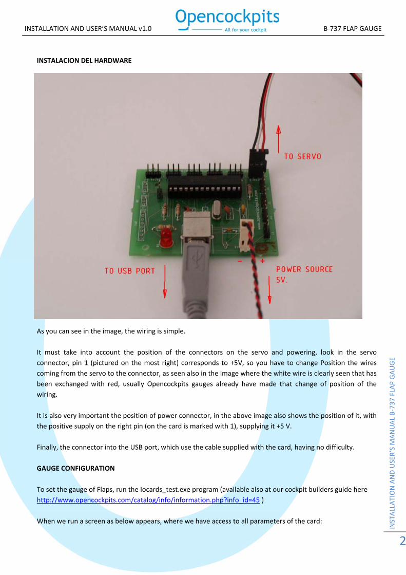
INSTALACION DEL HARDWARE
As you can see in the image, the wiring is simple. It must take into account the position of the connectors on the servo and powering, look in the servo connector, pin 1 (pictured on the most right) corresponds to +5V, so you have to change Position the wires coming from the servo to the connector, as seen also in the image where the white wire is clearly seen that has been exchanged with red, usually Opencockpits gauges already have made that change of position of the wiring. It is also very important the position of power connector, in the above image also shows the position of it, with the positive supply on the right pin (on the card is marked with 1), supplying it +5 V. Finally, the connector into the USB port, which use the cable supplied with the card, having no difficulty. GAUGE CONFIGURATION To set the gauge of Flaps, run the Iocards_test.exe program (available also at our cockpit builders guide here http://www.opencockpits.com/catalog/info/information.php?info_id=45 ) When we run a screen as below appears, where we have access to all parameters of the card:
INSTALLATION AND USER’S MANUAL v1.0 B‐737 FLAP GAUGE
INSTALLATION AND USER’S MANUAL B‐73
7 FLAP GAUGE
3
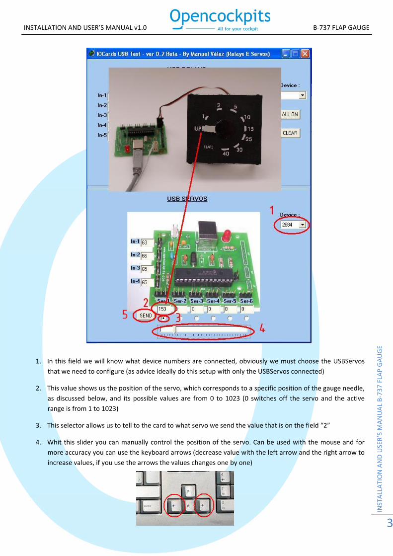
1. In this field we will know what device numbers are connected, obviously we must choose the USBServos that we need to configure (as advice ideally do this setup with only the USBServos connected)
2. This value shows us the position of the servo, which corresponds to a specific position of the gauge needle, as discussed below, and its possible values are from 0 to 1023 (0 switches off the servo and the active range is from 1 to 1023)
3. This selector allows us to tell to the card to what servo we send the value that is on the field “2”
4. Whit this slider you can manually control the position of the servo. Can be used with the mouse and for more accuracy you can use the keyboard arrows (decrease value with the left arrow and the right arrow to increase values, if you use the arrows the values changes one by one)
INSTALLATION AND USER’S MANUAL v1.0 B‐737 FLAP GAUGE
INSTALLATION AND USER’S MANUAL B‐73
7 FLAP GAUGE
4
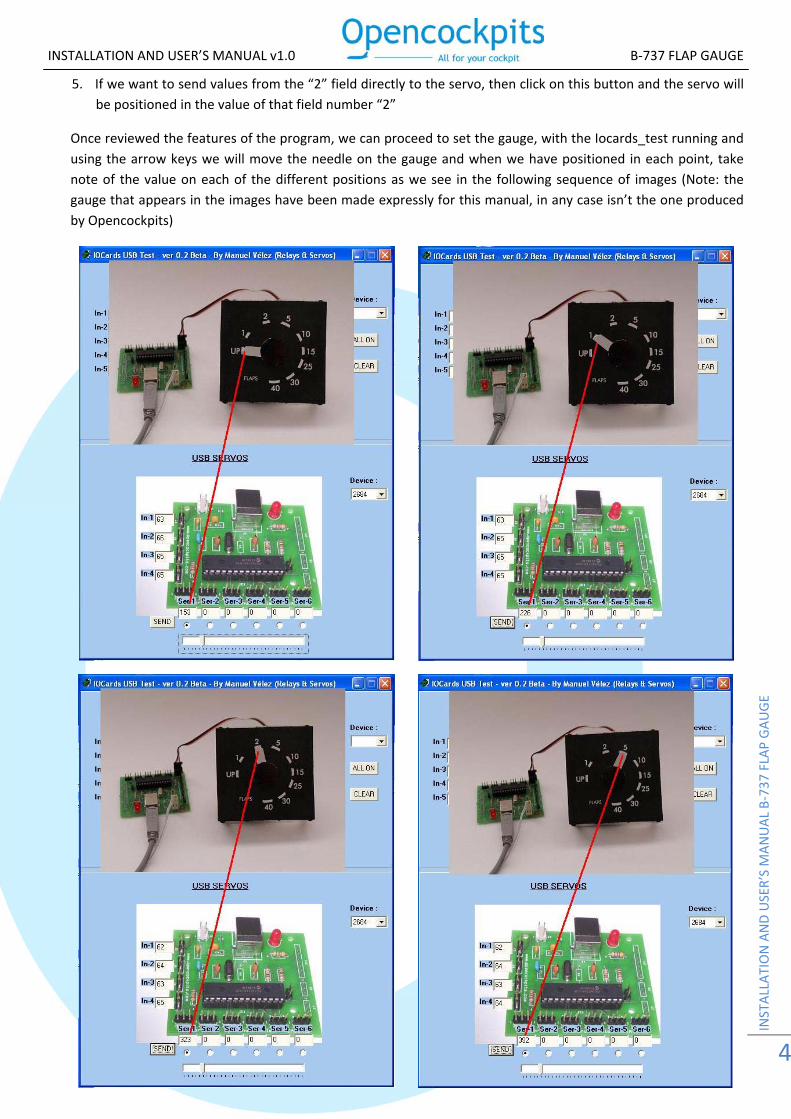
5. If we want to send values from the “2” field directly to the servo, then click on this button and the servo will be positioned in the value of that field number “2”
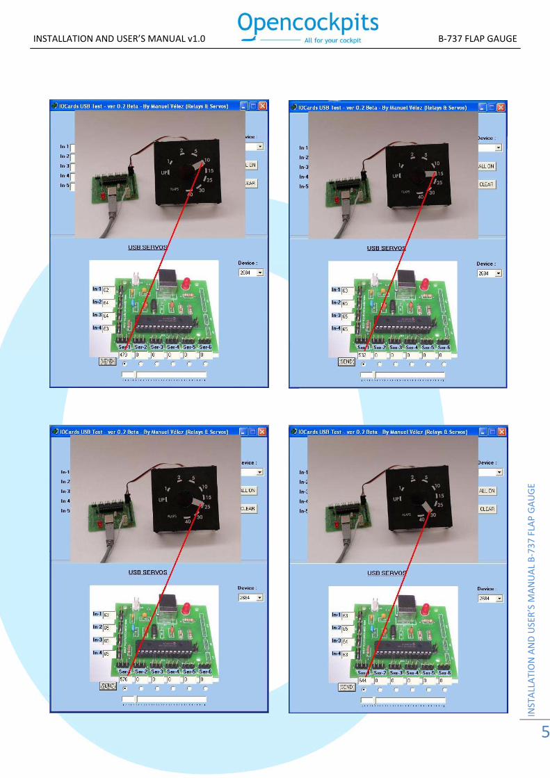
Once reviewed the features of the program, we can proceed to set the gauge, with the Iocards_test running and using the arrow keys we will move the needle on the gauge and when we have positioned in each point, take note of the value on each of the different positions as we see in the following sequence of images (Note: the gauge that appears in the images have been made expressly for this manual, in any case isn’t the one produced by Opencockpits)
INSTALLATION AND USER’S MANUAL v1.0 B‐737 FLAP GAUGE
INSTALLATION AND USER’S MANUAL B‐73
7 FLAP GAUGE
5
INSTALLATION AND USER’S MANUAL v1.0 B‐737 FLAP GAUGE
INSTALLATION AND USER’S MANUAL B‐73
7 FLAP GAUGE
6
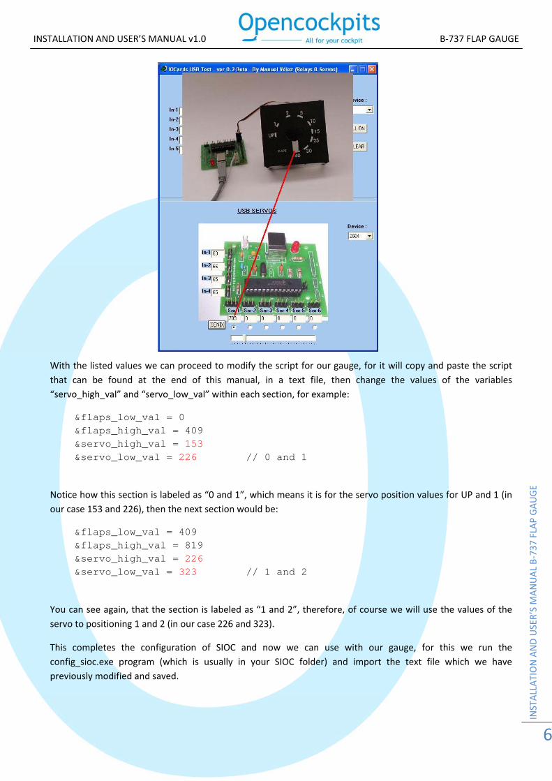
With the listed values we can proceed to modify the script for our gauge, for it will copy and paste the script that can be found at the end of this manual, in a text file, then change the values of the variables “servo_high_val” and “servo_low_val” within each section, for example:
&flaps_low_val = 0 &flaps_high_val = 409 &servo_high_val = 153 &servo_low_val = 226 // 0 and 1
Notice how this section is labeled as “0 and 1”, which means it is for the servo position values for UP and 1 (in our case 153 and 226), then the next section would be:
&flaps_low_val = 409 &flaps_high_val = 819 &servo_high_val = 226 &servo_low_val = 323 // 1 and 2
You can see again, that the section is labeled as “1 and 2”, therefore, of course we will use the values of the servo to positioning 1 and 2 (in our case 226 and 323).
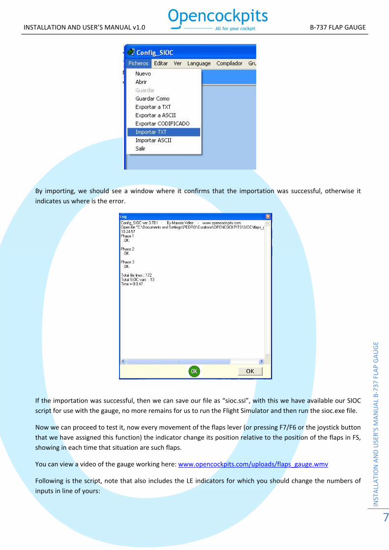
This completes the configuration of SIOC and now we can use with our gauge, for this we run the config_sioc.exe program (which is usually in your SIOC folder) and import the text file which we have previously modified and saved.
INSTALLATION AND USER’S MANUAL v1.0 B‐737 FLAP GAUGE
INSTALLATION AND USER’S MANUAL B‐73
7 FLAP GAUGE
7
By importing, we should see a window where it confirms that the importation was successful, otherwise it indicates us where is the error.
If the importation was successful, then we can save our file as “sioc.ssi”, with this we have available our SIOC script for use with the gauge, no more remains for us to run the Flight Simulator and then run the sioc.exe file.
Now we can proceed to test it, now every movement of the flaps lever (or pressing F7/F6 or the joystick button that we have assigned this function) the indicator change its position relative to the position of the flaps in FS, showing in each time that situation are such flaps.
You can view a video of the gauge working here: www.opencockpits.com/uploads/flaps_gauge.wmv
Following is the script, note that also includes the LE indicators for which you should change the numbers of inputs in line of yours:

INSTALLATION AND USER’S MANUAL v1.0 B‐737 FLAP GAUGE
INSTALLATION AND USER’S MANUAL B‐73
7 FLAP GAUGE
8
Var 0000, Value 0 { &ind_le_extend = 0 &ind_le_trans = 0 } Var 0001, name servo_flaps, Link USB_SERVOS, Output 1, PosL 0, PosC 511, PosR 1023 Var 0002, name flaps_fsuipc, Link FSUIPC_IN, Offset $0BE0, Length 4 { L0 = &flaps_fsuipc L0 = ABS L0 IF L0 = 0 { &ind_le_extend = 0 &ind_le_trans = 0 } ELSE { L1 = 0 &ind_le_trans = 1 IF L0 = 409 { L1 = 1 &ind_le_trans = 0 } IF L0 = 819 { L1 = 1 &ind_le_trans = 0 } IF L0 = 2047 { L1 = 1 &ind_le_trans = 0 } IF L0 = 4095 { L1 = 1 &ind_le_trans = 0 } IF L0 = 6143 { L1 = 1 &ind_le_trans = 0 } IF L0 = 10239 { L1 = 1 &ind_le_trans = 0 } IF L0 = 12287 { L1 = 1 &ind_le_trans = 0 } IF L0 = 16383 { L1 = 1 &ind_le_trans = 0 } &ind_le_extend = L1 } L2 = L0 C0 = L0 >= 0 C1 = L0 <= 409 IF C0 AND C1 { &flaps_low_val = 0 &flaps_high_val = 409

INSTALLATION AND USER’S MANUAL v1.0 B‐737 FLAP GAUGE
INSTALLATION AND USER’S MANUAL B‐73
7 FLAP GAUGE
9
&servo_high_val = 153 &servo_low_val = 226 // 0 and 1 } C0 = L0 >= 409 C1 = L0 <= 819 IF C0 AND C1 { &flaps_low_val = 409 &flaps_high_val = 819 &servo_high_val = 226 &servo_low_val = 323 // 1 and 2 } C0 = L0 >= 819 C1 = L0 <= 2047 IF C0 AND C1 { &flaps_low_val = 819 &flaps_high_val = 2047 &servo_high_val = 323 &servo_low_val = 412 // 2 and 5 } C0 = L0 >= 2047 C1 = L0 <= 4095 IF C0 AND C1 { &flaps_low_val = 2047 &flaps_high_val = 4095 &servo_high_val = 412 &servo_low_val = 466 // 5 and 10 } C0 = L0 >= 4095 C1 = L0 <= 6143 IF C0 AND C1 { &flaps_low_val = 4095 &flaps_high_val = 6143 &servo_high_val = 466 &servo_low_val = 532 // 10 and 15 } C0 = L0 >= 6143 C1 = L0 <= 10239 IF C0 AND C1 { &flaps_low_val = 6143 &flaps_high_val = 10239 &servo_high_val = 532 &servo_low_val = 576 // 15 and 25 } C0 = L0 >= 10239 C1 = L0 <= 12287 IF C0 AND C1 { &flaps_low_val = 10239 &flaps_high_val = 12287 &servo_high_val = 576 &servo_low_val = 644 // 25 and 30 } C0 = L0 >= 12287 C1 = L0 <= 16383 IF C0 AND C1 { &flaps_low_val = 12287 &flaps_high_val = 16383 &servo_high_val = 644 &servo_low_val = 709 // 30 and 40 } &servo_calc = &servo_low_val - &servo_high_val &flaps_calc = &flaps_high_val - &flaps_low_val &flaps_val = L0 - &flaps_low_val &servo_val = &servo_calc * &flaps_val &servo_val = &servo_val / &flaps_calc

INSTALLATION AND USER’S MANUAL v1.0 B‐737 FLAP GAUGE
INSTALLATION AND USER’S MANUAL B‐73
7 FLAP GAUGE
1
L1 = &servo_high_val + &servo_val &servo_flaps = L1 } Var 0003, name servo_val Var 0004, name flaps_calc Var 0005, name servo_calc Var 0006, name flaps_val Var 0007, name flaps_low_val Var 0008, name flaps_high_val Var 0009, name servo_high_val Var 0010, name servo_low_val Var 0011, name ind_le_extend, Link IOCARD_OUT, Output 22 Var 0012, name ind_le_trans, Link IOCARD_OUT, Output 21
Note:
Software programs, circuits and content published in this paper and on our website are copyrighted by their developers, who doesn't consent to their use for commercial gain, unless authorized in writing.
The software and content published and any code developed can be distributed as often as necessary and through desired media without written authorization, provided that the publication is acknowledged to the author and the source from which comes
www.opencockpits.com