Installation and Setup Guide -...
52
Installation and Setup Guide Color Touchscreen Programmable Thermostat ComfortSense ® 7500 (13H14)
Transcript of Installation and Setup Guide -...

Installation and SetupGuide
Color Touchscreen
Programmable Thermostat
ComfortSense® 7500 (13H14)
2
Table of Contents
Shipping and Packing List 2. . . . . . . . . . . . . . .
ComfortSense® 7500 Thermostat 3. . . . . . . .
Features 3. . . . . . . . . . . . . . . . . . . . . . . . . . . . .
Thermostat Installation
Mounting Thermostat 6. . . . . . . . . . . . . . . . . . .
Wiring Thermostat 11. . . . . . . . . . . . . . . . . . . . .
Installer Settings
Menu (Installer Settings) 21. . . . . . . . . . . . . . .
Humidity 37. . . . . . . . . . . . . . . . . . . . . . . . . . . . .
Dehumidity 38. . . . . . . . . . . . . . . . . . . . . . . . . .
Unit Part (Catalog) and Serial Number 41. . . .
Memory Protection 41. . . . . . . . . . . . . . . . . . . .
Appendix A. Flow Diagrams 42. . . . . . . . . . . .
Appendix B. Diagnostic Information 43. . . . . .
Appendix C. Supported Configurations 47. . .
Appendix D. Installer Checklist 49. . . . . . . . . .
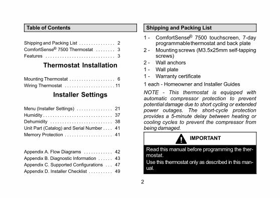
Shipping and Packing List
1 - ComfortSense® 7500 touchscreen, 7-dayprogrammable thermostat and back plate
2 - Mounting screws (M3.5x25mm self-tappingscrews)
2 - Wall anchors
1 - Wall plate
1 - Warranty certificate
1 each - Homeowner and Installer Guides
NOTE - This thermostat is equipped withautomatic compressor protection to preventpotential damage due to short cycling or extendedpower outages. The short-cycle protectionprovides a 5-minute delay between heating orcooling cycles to prevent the compressor frombeing damaged.
IMPORTANT
Read this manual before programming the thermostat.
Use this thermostat only as described in this manual.
3
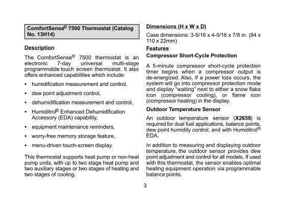
ComfortSense® 7500 Thermostat (CatalogNo. 13H14)
Description
The ComfortSense® 7500 thermostat is anelectronic 7-day universal multi‐stageprogrammable touch screen thermostat. It alsooffers enhanced capabilities which include:
� humidification measurement and control,
� dew point adjustment control,
� dehumidification measurement and control,
� Humiditrol® Enhanced DehumidificationAccessory (EDA) capability,
� equipment maintenance reminders,
� worry-free memory storage feature,
� menu-driven touch-screen display.
This thermostat supports heat pump or non-heatpump units, with up to two stage heat pump andtwo auxiliary stages or two stages of heating andtwo stages of cooling.
Dimensions (H x W x D)
Case dimensions: 3-5/16 x 4-5/16 x 7/8 in. (84 x110 x 22mm)
Features
Compressor Short-Cycle Protection
A 5-minute compressor short-cycle protectiontimer begins when a compressor output isde-energized. Also, if a power loss occurs, thesystem will go into compressor protection modeand display “waiting” next to either a snow flakeicon (compressor cooling), or flame icon(compressor heating) in the display.
Outdoor Temperature Sensor
An outdoor temperature sensor (X2658) isrequired for dual fuel applications, balance points,dew point humidity control, and with Humiditrol®
EDA.
In addition to measuring and displaying outdoortemperature, the outdoor sensor provides dewpoint adjustment and control for all models. If usedwith this thermostat, the sensor enables optimalheating equipment operation via programmablebalance points.
4
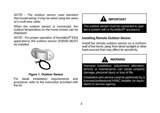
NOTE - The outdoor sensor uses standardthermostat wiring; it may be wired using two wiresof a multi-wire cable.
When the outdoor sensor is connected, theoutdoor temperature on the home screen can bedisplayed.
NOTE - For proper operation of Humiditrol® EDAapplications, the outdoor sensor (X2658) MUSTbe installed.
Figure 1. Outdoor Sensor
For detail installation requirements andprocedure, refer to the instruction provided withthe kit.
IMPORTANT
The outdoor sensor must be connected to operate a system with a Humiditrol® accessory.
Installing Remote Outdoor Sensor
Install the remote outdoor sensor on a northernwall of the home, away from direct sunlight or otherheat sources that may affect its sensitivity.
WARNING
Improper installation, adjustment, alteration,service or maintenance can cause propertydamage, personal injury or loss of life.
Installation and service must be performed by alicensed professional HVAC installer (or equivalent) or service agency.

5
CAUTION
This is a 24VAC low-voltage thermostat. Do notinstall on voltages higher than 30VAC.
Do not short (jumper) across terminals on thegas valve or at the system control to test installation. This will damage the thermostat and voidthe warranty.
IMPORTANT
In all applications, the ComfortSense® Model7500 thermostat can only be used with allresidential units and approved commercialsplit‐system matches, and those which meetthe following installation criteria:
� installation uses 18 GAUGE thermostatwire or larger,
� thermostat wire run length DOES NOTEXCEED 300' (91m),
� load from any thermostat connection is 1AMP or LESS.
CAUTION
Always turn off power at the main power sourceby switching the circuit breaker to the OFF position before installing or removing this thermostat.
All wiring must conform to local and nationalbuilding and electrical codes and ordinances.
6
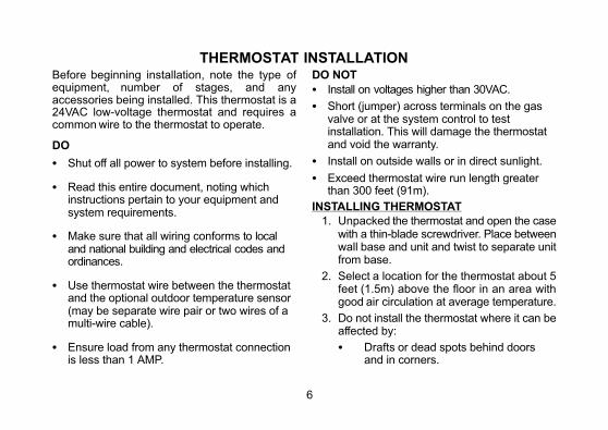
THERMOSTAT INSTALLATIONBefore beginning installation, note the type ofequipment, number of stages, and anyaccessories being installed. This thermostat is a24VAC low-voltage thermostat and requires acommon wire to the thermostat to operate.
DO
� Shut off all power to system before installing.
� Read this entire document, noting whichinstructions pertain to your equipment andsystem requirements.
� Make sure that all wiring conforms to localand national building and electrical codes andordinances.
� Use thermostat wire between the thermostatand the optional outdoor temperature sensor(may be separate wire pair or two wires of amulti-wire cable).
� Ensure load from any thermostat connectionis less than 1 AMP.
DO NOT
� Install on voltages higher than 30VAC.
� Short (jumper) across terminals on the gasvalve or at the system control to testinstallation. This will damage the thermostatand void the warranty.
� Install on outside walls or in direct sunlight.
� Exceed thermostat wire run length greaterthan 300 feet (91m).
INSTALLING THERMOSTAT
1. Unpacked the thermostat and open the casewith a thin-blade screwdriver. Place betweenwall base and unit and twist to separate unitfrom base.
2. Select a location for the thermostat about 5feet (1.5m) above the floor in an area withgood air circulation at average temperature.
3. Do not install the thermostat where it can beaffected by:
� Drafts or dead spots behind doorsand in corners.

7
� Not close to entrance or automaticdoors
� Not close to heat generatingequipment such as kitchen equipment
� Not in an enclose environment unlessa remote indoor sensor is used.
� Hot or cold air from ducts.
� Radiant heat from sun or appliances.
� Concealed pipes and chimneys.
� Unheated (uncooled) areas such asan outside wall behind the thermostat.
Figure 2. Removing Back Plate
4. Use steps A through J (step J applicablewhen using provided wall plate) to install thethermostat.
CUT OR DRILL A SMALL HOLE
FOR THERMOSTAT WIRING
¾” x ¾”
A
B
PULL ABOUT 3” OF THERMOSTAT
WIRE THROUGH OPENING AND RE
MOVE OUTER THERMOSTAT WIRE
JACKET.
THIS WILL HELP IN
ROUTING THE THER
MOSTAT WIRING TO
THE PROPER THER
MOSTAT TERMINALS
8
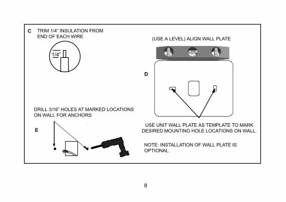
1/4”
TRIM 1/4” INSULATION FROM
END OF EACH WIREC
USE UNIT WALL PLATE AS TEMPLATE TO MARK
DESIRED MOUNTING HOLE LOCATIONS ON WALL.
D
(USE A LEVEL) ALIGN WALL PLATE
DRILL 3/16” HOLES AT MARKED LOCATIONS
ON WALL FOR ANCHORS
E
NOTE: INSTALLATION OF WALL PLATE IS
OPTIONAL.
9
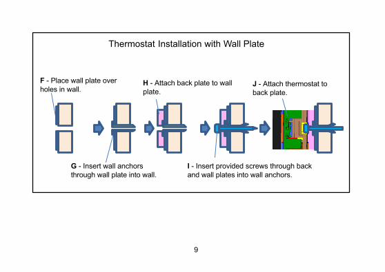
Thermostat Installation with Wall Plate
F - Place wall plate over
holes in wall.
G - Insert wall anchors
through wall plate into wall.
H - Attach back plate to wall
plate.
I - Insert provided screws through back
and wall plates into wall anchors.
J - Attach thermostat to
back plate.
10
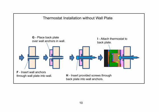
Thermostat Installation without Wall Plate
G - Place back plate
over wall anchors in wall.
F - Insert wall anchors
through wall plate into wall. H - Insert provided screws through
back plate into wall anchors.
I - Attach thermostat to
back plate.

11
WIRING THERMOSTAT
Thermostat wiring connections with various units,including dual fuel, zone control, and applicationsthat include the Humiditrol® EnhancedDehumidification Accessory (EDA). See figures 3through 7. For whole home dehumidifier, refer tothe installation instruction for the dehumidifier.
1. Connect wiring between thermostat, indoorunit, and outdoor unit as shown in theappropriate wiring diagram.
2. Connect the outdoor sensor (if used) to theT connections on the thermostat (wire runshould not exceed 300' [100m]).
3. Seal the hole in the wall with a suitablematerial to prevent drafts from entering thethermostat case.
4. Configure thermostat and equipment forsystem type, program the thermostat, andtest system.
TERMINAL DESIGNATIONSTc - Outdoor Temp. Sensor Connection 1 (Opt.)
To - Outdoor Temp. Sensor Connection 2 (Opt.)
H - Humidification relay (to Humidifier)D - Dehumidification relay (to DS terminal)
W2 - Second-stage heating (non-heat pump) or 4thstage (heat pump)
Y2 - Second-stage heating or cooling
O - Cool active reversing valve
B - Heat active reversing valveC - Common 24VAC
G - Fan relayW1 - First-stage heating (non-heat pump or
emergency heat) or third-stage heating(heat pump)
Y1 - First-stage heating or coolingR - 24VAC power

12
Tc
To
H
D
W2
Y2
O
B
C
G
W1
Y1
R
W2
R
Y2
Y1
DS
C
G
R
C
D
R
Y2
Y1
C
FA
N R
ELA
Y EDA UNIT
TY
PIC
AL
TW
O−
ST
AG
E O
UT
DO
OR
UN
IT
THERMOSTAT
OUTDOORSENSOR (x2658)
NOTE: FAN RELAY NOT REQUIRED
WITH SINGLE SPEED OUTDOOR FAN.
NOTE: SEE EDA INSTALLATION
INSTRUCTION FOR FAN CONTACT
WIRING.
PURPLE
BLACK
RED
NOT REQUIRED
REMOVE Y1 TO DS OR
R TO DS JUMPER ON
INDOOR UNIT FOR
HUMIDITROL
APPLICATIONS
Y1-Y2 JUMPER (OR ON-BOARD
CLIPPABLE LINK) – IN FOR SINGLE
-STAGE COOLING; REMOVED FOR 2-
STAGE COOLING.
SINGLE STAGEFOR
TYPICAL INDOOR UNIT
(SEE SPECIFIC MODEL DOCU
MENTATION FOR ACTUAL TERMINAL LAYOUT.
Figure 3. Enhanced Dehumidification Accessory Typical Wiring Diagram
13
Tc
To
To
Tc
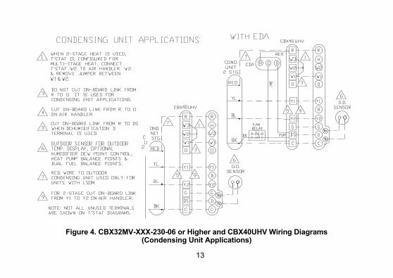
Figure 4. CBX32MV-XXX-230-06 or Higher and CBX40UHV Wiring Diagrams(Condensing Unit Applications)
14
To
Tc
To
Tc
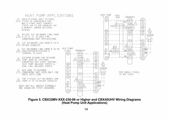
Figure 5. CBX32MV-XXX-230-06 or Higher and CBX40UHV Wiring Diagrams(Heat Pump Unit Applications)

15
CBX25UH AND CBX25UHV DO NOT HAVE TERMINALSTRIPS IN UNIT.
OUTDOOR SENSOR FOR OUTDOOR TEMPDISPLOAY, OPTIONAL HUMIDIFIER DEW POINTCONTROL, HEAT PUMP BALANCE POINTS ANDDUAL-FUEL BALANCE POINTS.
REMOVE DS-TO-Y1 JUMPER WHENDEHUMIDIFICAITON D TERMINAL IS USED.
CUT ON-BOARD LINK FROM R-TO-O (W951CLIPPABLE CONNECTION ON FURNACE / JUMPERON AIR HANDLER).
DO NOT CUT -ON-BOARD LINK FORM R-TO-O (W951CLIPPABLE CONNECTION ON FURNACE / JUMPERON AIR HANDLER) WHEN IT IS USED FORCONDENSING UNIT APPLICATIONS.
CUT ON-BOARD LINK FORM DS-TO-R (W914CLIPPABLE CONNECTION ON FURNACE / JUMPERON AIR HANDLER) WHEN DEHUMIDIFICAITON ORHARMONY CONTROL IS USED.
WHEN 2-STAGE HEAT IS USED, THERMOSTAT ISCONFIGURED FOR MULIT-STAGE HEAT, CONNECTTHERMOSTAT W2 TO AIR HANDLER W2 ANDREMOVE JUMPER BETWEEN R AND W2.
K183 DEHUMIDIFICATION RELAY KIT (26W62)REQUIRED WHEN USING D-TO-DS TERMINALSWITH CBX27 UNITS.
FOR 2-STAGE CUT ON-BOARD LINK FROM Y1-TO-Y2(W915 CLIPPABLE CONNECTION ON FURNACE /JUMPER ON AIR HANDLER).
FOR HUMIDIFIER, 48G95 OR EQUIVALENTISOLATION RELAY REQUIRED - 24VAC, 5VA MAXCAN BE USED WITH ALL THERMOSTATAPPLICATIONS.
NOTE: NOT ALL UNUSED TERMINALS ARE SHOWNON THE THERMOSTAT DIAGRAMS.
Figure 6. Key for Figures 7 through 11.
16
TSTAT
TSTAT
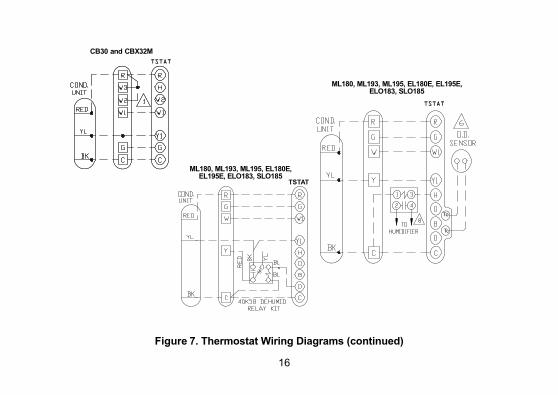
ML180, ML193, ML195, EL180E, EL195E,ELO183, SLO185
TSTAT
ML180, ML193, ML195, EL180E,EL195E, ELO183, SLO185
To
Tc
CB30 and CBX32M
Figure 7. Thermostat Wiring Diagrams (continued)
17
TSTAT
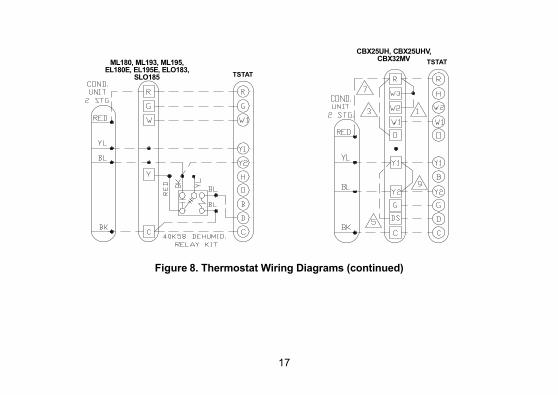
ML180, ML193, ML195,EL180E, EL195E, ELO183,
SLO185
CBX25UH, CBX25UHV,CBX32MV
TSTAT
Figure 8. Thermostat Wiring Diagrams (continued)
18
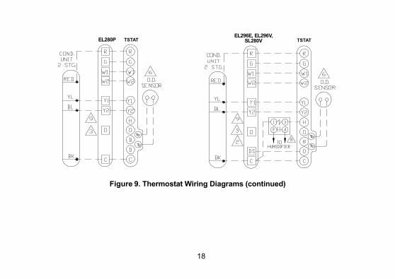
TSTATEL280P TSTATEL296E, EL296V,
SL280V
To
Tc
To
Tc
Figure 9. Thermostat Wiring Diagrams (continued)

19
TSTAT
CBX25UH,CBX25UHV,CBX27UH TSTAT
CBX25UH,CBX25UHV,CBX32MV
To
Tc
To
Tc
Figure 10. Thermostat Wiring Diagrams (continued)

20
TSTAT
ML180, ML193, ML195,EL180E, EL195E,ELO183, SLO185 TSTAT
EL296E, SL280V,EL296V, SLP98
To
Tc
To
Tc
Figure 11. Thermostat Wiring Diagrams (continued)
21
Settings
menu
performance report
notifications 13
edit schedules
settings
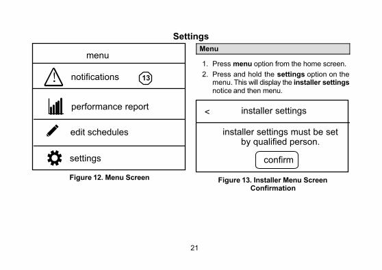
Figure 12. Menu Screen
Menu
1. Press menu option from the home screen.
2. Press and hold the settings option on themenu. This will display the installer settingsnotice and then menu.
installer settings
confirm
<
installer settings must be setby qualified person.
Figure 13. Installer Menu ScreenConfirmation
22
SYSTEM SETUP
Sets the thermostat for operation with either anon-heat pump or heat pump and defines thenumber of compressor stages. Indoor unitsettings include no heat, gas/oil or electric andnumber of indoor heat stages.
OUTDOOR SENSOROptions are yes or no (default).
RESIDUAL COOL
Default is 0 seconds. This is the time, in seconds,that the fan runs after a call for cooling is satisfiedin order to deliver any residual cooling ability fromthe coil and ductwork into the conditioned space.Options are 0, 30, 60, 90 and 120 minutes. Press <to return to previous menu.
LOW AND HIGH BALANCE POINTS
These balance points are for heat pump systemsonly with an outdoor sensor installed and enabled.
� When in heat mode and the outdoortemperature is below the programmed LowBalance Point, then heat pump heating is notallowed and only backup heat will be used.
� When in heat mode and the outdoortemperature is above the programmed HighBalance Point, then heat pump heating isallowed and backup heat will not be used.
� When in heat mode and the outdoortemperature is between the programmed Lowand High Balance Points, then heat pumpheating and backup heat can be used.
Options are enable or disable. Default for both isdisable. Once enabled, the following settings areavailable.
Low Balance Point Default is 25°F. Adjustablerange is -40°F to 48°F.
High Balance Point Default is 50°F. Adjustablerange is 50°F to 75°F.

23
Table 1. Smooth Set back Recovery (SSR) & SSR Stg 2 Lock Out Operation
Equipment Available SSR = Enabled; SSR Stg 2 lock out = enabled
SSR = Enabled; SSR Stg 2 lock-out = disabled (off)
1 stage HP with 1 or 2stages electric backup
Run HP (Y1) only; all backupheat (W1/W2) enabled 20 -120 min before wake up setpoint
Run HP (Y1) and have available backupheat (W1/W2) as needed.
2 stage HP with 1 or 2stages electric backup
Run HP (Y1/Y2) only; allbackup heat (W1/W2) enabled 20 - 120 min beforewake up setpoint
Run HP (Y1/Y2) and have availablebackup heat (W1/W2) as needed.
1 stage HP with 1 stagegas/oil backup
Run HP (Y1) only; all backupheat (W1) enabled 20 - 120min before wake up setpoint
Run HP (Y1) until a 2nd stage demand isneeded (by time/temp. differential); thenHP operation must stop and changeoverand lock in to W1 heat until setpointreached.
1 stage HP with 2 stagesgas/oil backup or modulation furnace
Run HP (Y1) only; all backupheat (W1/W2) enabled 20 -120 min before wake up setpoint
Run HP (Y1) until a 2nd stage demand isneeded (by time/temp differential); thenHP operation must stop and changeoverto W1/W2 heat as needed; lock inW1/W2 heat until setpoint reached.
24
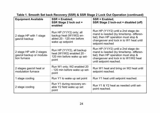
Table 1. Smooth Set back Recovery (SSR) & SSR Stage 2 Lock Out Operation (continued)
Equipment Available SSR = Enabled; SSR Stage 2 lock out =enabled
SSR = Enabled; SSR Stage 2 lock-out = disabled (off)
2 stage HP with 1 stagegas/oil backup
Run HP (Y1/Y2) only; allbackup heat (W1/W2) enabled 20 - 120 min beforewake up setpoint
Run HP (Y1/Y2) until a 2nd stage demand is needed (by time/temp. differential); then HP operation must stop &changeover and lock in to W1 heat untilsetpoint reached
2 stage HP with 2 stagesgas/oil backup or modulation furnace
Run HP (Y1/Y2), all backupheat (W1/W2) enabled 20 -120 min before wake up setpoint
Run HP (Y1/Y2) until a 2nd stage demand is needed (by time/temp. differential); then HP operation must stop &changeover and lock in to W1/W2 heatuntil setpoint reached.
2 stages gas/oil heat ormodulation furnace
Run W1 only; W2 enabled 20- 120 min before wake up setpoint
Run W1 heat and bring on W2 heat untilsetpoint reached.
1 stage cooling Run Y1 to wake up set point Run Y1 heat until setpoint reached.
2 stage coolingRun Y1 during recovery enable Y2 field wake up setpoint
Run Y1 & Y2 heat as needed until setpoint reached.
25
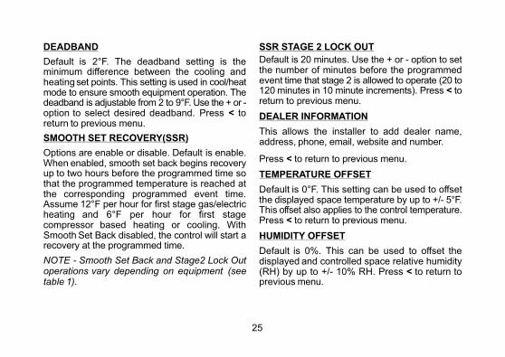
DEADBAND
Default is 2°F. The deadband setting is theminimum difference between the cooling andheating set points. This setting is used in cool/heatmode to ensure smooth equipment operation. Thedeadband is adjustable from 2 to 9°F. Use the + or -option to select desired deadband. Press < toreturn to previous menu.
SMOOTH SET RECOVERY(SSR)
Options are enable or disable. Default is enable.When enabled, smooth set back begins recoveryup to two hours before the programmed time sothat the programmed temperature is reached atthe corresponding programmed event time.Assume 12°F per hour for first stage gas/electricheating and 6°F per hour for first stagecompressor based heating or cooling. WithSmooth Set Back disabled, the control will start arecovery at the programmed time.
NOTE - Smooth Set Back and Stage2 Lock Outoperations vary depending on equipment (seetable 1).
SSR STAGE 2 LOCK OUT
Default is 20 minutes. Use the + or - option to setthe number of minutes before the programmedevent time that stage 2 is allowed to operate (20 to120 minutes in 10 minute increments). Press < toreturn to previous menu.
DEALER INFORMATION
This allows the installer to add dealer name,address, phone, email, website and number.
Press < to return to previous menu.
TEMPERATURE OFFSET
Default is 0°F. This setting can be used to offsetthe displayed space temperature by up to +/- 5°F.This offset also applies to the control temperature.Press < to return to previous menu.
HUMIDITY OFFSET
Default is 0%. This can be used to offset thedisplayed and controlled space relative humidity(RH) by up to +/- 10% RH. Press < to return toprevious menu.
26
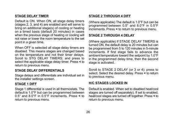
STAGE DELAY TIMER
Default is ON. When ON, all stage delay timers(stages 2, 3, and 4) are enabled and will serve tobring on additional stage(s) of cooling or heatingon a timed basis (default 20 minutes) in caseswhen the previous stage of heating or cooling willnot raise or lower the room temperature to the setpoint in a given time.
When OFF is selected all stage delay timers aredisabled. This means stages are changed basedon the temperature and not their timer delays.Scroll to STG DELAY TIMERS; and press toselect the applicable stage delay timer. Press < toreturn to previous menu.
STAGE DELAY DIFFERENTIALS
Stage delays and differentials are individual set inthe installer settings screen.
STAGE 1 DIFF
Stage 1 differential is used in all thermostats. Thedefault is 1.0°F but can be programmed between0.5° and 8.0°F in 0.5°F increments. Press < toreturn to previous menu.
STAGE 2 THROUGH 4 DIFF
(Where applicable) The default is 1.0°F but can beprogrammed between 0.5° and 8.0°F in 0.5°Fincrements. Press < to return to previous menu.
STAGE 2 THROUGH 4 DELAY
(Where applicable) If STAGE DELAY TIMERS isturned ON, the default delay is 20 minutes but canbe programmed from 5 to 120 minutes in 5-minuteincrements. If first stage fails to advance theambient temperature toward the setpoint by 1.0°Fin the programmed delay time, then the secondstage is activated.
Scroll to STAGE 2 DELAY (or 3 or 4); press toselect. Select the desired delay. Press < to returnto previous menu.
H/C STAGES LOCKED IN
Default is enabled. When set to disabled heat/coolstages are turned off separately). If set to enabled,heat/cool stages are turned off together. Press < toreturn to previous menu.

27
STAGE 2 HP LOCK TEMP
Default is off (heat pump stage 2 operatesnormally). Use this setting in dual fuel applicationsto lock in the 2nd stage compressor when theoutdoor temperature is at or less than the LOCK
TEMP set point. Scroll to STAGE 2 HP LOCKTEMP; press ENTER. Use - + option to select aLOCK TEMP between -40 and 75ºF. Press < toreturn to previous menu.
Configuration Figures
Multi-stage Cooling for Heat Pump/Non-Heat Pump 14
Heating - Non-Heat Pump (1 or 2 stages) 15
Heating - Heat Pump with NO backup heat 10
Heating - Heat Pump w/electric heat (2-stage: 1compr/1backup) 10
Heating - Heat Pump w/electric heat (3 stage: 2compr/1backup) 11
Heating - Heat Pump w/electric heat (3 stage: 1compr/2backup) 11
Heating - Heat Pump w/electric heat (4 stage: 2compr/2backup) 12
Heating - dual fuel (2-stage: 1compr/1backup) 13
Heating - dual fuel (3 stage: 1compr/2backup) 14
Heating - dual fuel (3 stage: 2compr/1backup) 15
Heating - dual fuel (4 stage: 2compr/2backup) 16
28
H/CStagesLocked =YES
H/CStagesLocked =NO
SETPOINTS:
2nd stageON
2nd stageOFF
1st stageON
1st stageOFF
2nd stageON
2nd stageOFF
1st stageON
1st stageOFF
SP -1.5 SP -1.0 SP -0.5 SP SP +1.5SP +1.0SP +0.5 SP +2.0
Stg1 Differential
Stg2 Differential
Stg2 Differential
Stg1 Differential
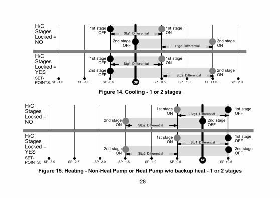
Figure 14. Cooling - 1 or 2 stages
H/CStagesLocked =YES
H/CStagesLocked =NO
1st stageON
2nd stageON
1st stageON
2nd stageON
2nd stageOFF
1st stageOFF
1st stageOFF
2nd stageOFF
SP -1.5 SP -1.0 SP -0.5SP
SP +0.5SP -2.0
Stg1 Differential
Stg2 Differential
SP -2.5SP -3.0
Stg1 Differential
Stg2 Differential
SETPOINTS:
Figure 15. Heating - Non-Heat Pump or Heat Pump w/o backup heat - 1 or 2 stages
29
H/CStagesLocked =NO
H/CStagesLocked =YES
SETPOINTS:
3rd stageON
1st stageON
2nd stageON
3rd stageON
1st stageON
2nd stageON
2nd stageOFF
3rd stageOFF
1st stageOFF
1st stageOFF
2nd stageOFF
3rd stageOFF
SP -1.5 SP -1.0 SP -0.5SP
SP +0.5SP -2.0
Stg1 Differential
Stg3 Differential
Stg2 Differential
SP -2.5SP -3.0SP -3.5
Stg1 Differential
Stg3 Differential
Stg2 Differential
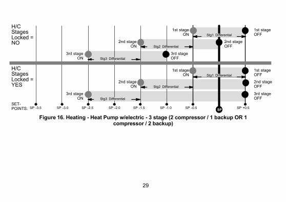
Figure 16. Heating - Heat Pump w/electric - 3 stage (2 compressor / 1 backup OR 1compressor / 2 backup)
30
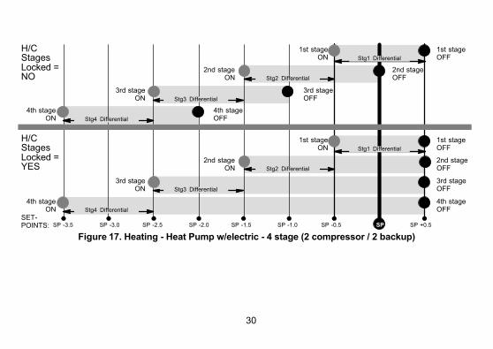
H/CStagesLocked =YES
H/CStagesLocked =NO
3rd stageON
1st stageON
2nd stageON
4th stageON
3rd stageON
1st stageON
2nd stageON
4th stageON
2nd stageOFF
3rd stageOFF
4th stageOFF
1st stageOFF
Stg4 Differential
1st stageOFF
2nd stageOFF
3rd stageOFF
4th stageOFF
SETPOINTS: SP -1.5 SP -1.0 SP -0.5 SP SP +0.5SP -2.0
Stg1 Differential
Stg3 Differential
Stg2 Differential
SP -2.5SP -3.0SP -3.5
Stg1 Differential
Stg3 Differential
Stg2 Differential
Stg4 Differential
Figure 17. Heating - Heat Pump w/electric - 4 stage (2 compressor / 2 backup)

31
H/CStagesLocked =NO orYES
2nd stageON
1st stageON
2nd stageOFF
1st stageOFF
SP -1.5 SP -1.0 SP -0.5SP
SP +0.5SP -2.0
Stg1 Differential
SP -2.5SP -3.0
Stg2 Differential
SETPOINTS:
Figure 18. Heating - dual fuel - 2 stage (1 compressor / 1 backup)
H/CStagesLocked =NO
H/CStagesLocked =YES
SETPOINTS:
3rd stageON
1st stageON
2nd stageON
3rd stageON
1st stageON
2nd stageON
2nd stageOFF
3rd stageOFF
1st stageOFF
1st stageOFF
2nd stageOFF
3rd stageOFF
SP -1.5 SP -1.0 SP -0.5SP
SP +0.5SP -2.0
Stg1 Differential
Stg3 Differential
Stg2 Differential
SP -2.5SP -3.0SP -3.5
Stg1 Differential
Stg3 Diff.
Stg2 Differential
Figure 19. Heating - dual fuel - 3 stage (1 compressor / 2 backup)
32
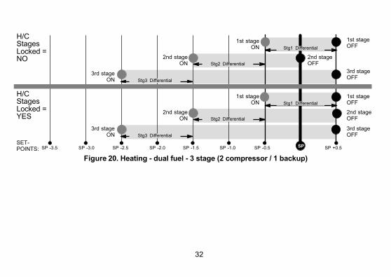
H/CStagesLocked =NO
H/CStagesLocked =YES
SETPOINTS:
3rd stageON
1st stageON
2nd stageON
3rd stageON
1st stageON
2nd stageON
2nd stageOFF
3rd stageOFF
1st stageOFF
1st stageOFF
2nd stageOFF
3rd stageOFF
SP -1.5 SP -1.0 SP -0.5 SP SP +0.5SP -2.0
Stg1 Differential
Stg3 Differential
Stg2 Differential
SP -2.5SP -3.0SP -3.5
Stg1 Differential
Stg3 Differential
Stg2 Differential
Figure 20. Heating - dual fuel - 3 stage (2 compressor / 1 backup)
33
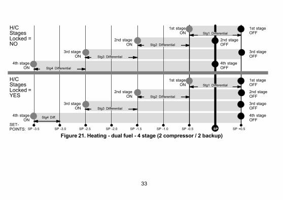
Stg4 Diff.
H/CStagesLocked =YES
H/CStagesLocked =NO
3rd stageON
1st stageON
2nd stageON
4th stageON
3rd stageON
1st stageON
2nd stageON
4th stageON
2nd stageOFF
3rd stageOFF
4th stageOFF
1st stageOFF
Stg4 Differential
1st stageOFF
2nd stageOFF
3rd stageOFF
4th stageOFF
SETPOINTS: SP -1.5 SP -1.0 SP -0.5 SP SP +0.5SP -2.0
Stg1 Differential
Stg3 Differential
Stg2 Differential
SP -2.5SP -3.0SP -3.5
Stg1 Differential
Stg3 Differential
Stg2 Differential
Figure 21. Heating - dual fuel - 4 stage (2 compressor / 2 backup)
34
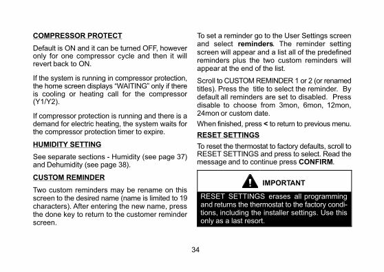
COMPRESSOR PROTECT
Default is ON and it can be turned OFF, howeveronly for one compressor cycle and then it willrevert back to ON.
If the system is running in compressor protection,the home screen displays “WAITING” only if thereis cooling or heating call for the compressor(Y1/Y2).
If compressor protection is running and there is ademand for electric heating, the system waits forthe compressor protection timer to expire.
HUMIDITY SETTING
See separate sections - Humidity (see page 37)and Dehumidity (see page 38).
CUSTOM REMINDER
Two custom reminders may be rename on thisscreen to the desired name (name is limited to 19characters). After entering the new name, pressthe done key to return to the customer reminderscreen.
To set a reminder go to the User Settings screenand select reminders. The reminder settingscreen will appear and a list all of the predefinedreminders plus the two custom reminders willappear at the end of the list.
Scroll to CUSTOM REMINDER 1 or 2 (or renamedtitles). Press the title to select the reminder. Bydefault all reminders are set to disabled. Pressdisable to choose from 3mon, 6mon, 12mon,24mon or custom date.
When finished, press < to return to previous menu.
RESET SETTINGS
To reset the thermostat to factory defaults, scroll toRESET SETTINGS and press to select. Read themessage and to continue press CONFIRM.
IMPORTANT
RESET SETTINGS erases all programmingand returns the thermostat to the factory conditions, including the installer settings. Use thisonly as a last resort.

35
Table 2. Energy Saving Set Points
NOTE - Humidification and dehumidification are not part of the energy savings program. A higher utility bill may occur whennot using the setpoints in this table.
Time Heating Cooling
Wake 70°F (21°C) 78°F (25°C)
Leave 62°F (17°C) 85°F (29°C)
Return 70°F (21C) 78°F (25°C)
Sleep 62°F (17°C) 82°F (28°C)
ENERGY SAVING DEFAULT
Energy saving recommended set points forheating and cooling can help save energy. Thetime and temperatures reference in table 2 arepre-programmed into the thermostat to achieveenergy savings.
Scroll to ENERGY SAVING DEFAULT; press toselect. Read the message on the screen and tocontinue, press CONFIRM.
SYSTEM TEST MODES
After the thermostat has been installed and set-up,the installer may run a system test function(accessed through the installer settings menu), totest all cooling, heating, emergency heatingstages and FAN outputs.
Select system test mode. A pop-up will bedisplayed indicating all equipment will be stopped.Press confirm to continue.
Pressing the OFF button next to the desired optionwill change the status to ON and will enable therelay for that terminal. Pressing again will turn OFFthe relay. Press the left arrow (<) to exit the systemtest mode.

36
system test mode
Y1 off
Y2 off
W1 off
W2 off
G off
H off
D off
OB o
NOTICERisk of equipment damage.
Can cause compressor failure.
In dual fuel system applications, do not turn onheat pump and furnace at the same time in system test mode.
All HVAC components can be tested to confirm thesignals between thermostat and unit are beingsent and were received.
NOTES: After 5 minutes without a test beinginitiated, the test modes is disabled and systemgoes back to the normal mode (i.e. HOMEscreen).
When in SYSTEM TEST MODE, the compressorminimum off timer is bypassed.

37
Humidify
Humidification (adding moisture to air) is providedonly when the thermostat is in heat mode. Thehumidification signal (H terminal) to the humidifier(off when the thermostat is in the COOL mode)controls humidification. When the thermostat ispowered, the H terminal is normally inactive (opencircuit) in any mode (HEAT/COOL, HEAT, COOL,OFF). When a humidification demand is present,H terminal and G terminal are energized (24V).
A selection option under Installer settings >Humidity settings > Humidify > Humidify modemust be enabled before the user will have controlover the humidity. The humidity mode selecteddetermines how the user can adjust the relativehumidity (RH). The installer settings includeNORMAL, MAX, DEW POINT NORMAL, DEWPOINT MAX, and OFF.
NORMAL & MAX
These thermostat modes allow the user to controlthe relative humidity (RH) between 15 and 45%.The following conditions must be met for eithermode to operate:
� humidification mode has been enabled, and
� the unit is in HEAT mode, and
� humidification demand exists (24V present atH)
Additionally, the NORMAL mode requires heatdemand exists (Y energized for heat pumpheating, or W energized for gas heat [W may beenergized with G de-energized]).
DEW POINT NORMAL & MAX
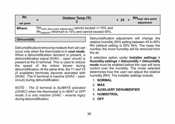
Dew point adjustment mode will change thehumidification set point based on the outdoortemperature and a user-defined dew pointadjustment setting.
NOTE - In dew point adjustment mode, thehumidification set point has no effect whatsoeveron unit operation. Only the user-defined dew pointadjustment setting affects operation per thefollowing formula:
38
Rh
set point
=Outdoor Temp (ºF)
2+ 25 +
RHuser dew point
adjustment
Where: RHuser dew point adjustment cannot exceed +/-15% andRhsetpoint minimum is 15% and cannot exceed 45%.
Dehumidify
Dehumidification (removing moisture from air) canoccur only when the thermostat is in cool mode.When a dehumidification demand is present, adehumidification signal (0VAC - open circuit) ispresent at the D terminal. This is used to reducethe speed of the indoor blower duringdehumidification. At the same time, the Y1 and Y2(if available) terminals become activated with24VAC. The H terminal is inactive (0VAC - opencircuit) during dehumidification.
NOTE - The D terminal is ALWAYS activated(24VAC) when the thermostat is in HEAT or OFFmode; it is only inactive (0VAC - reverse logic)during dehumidification.
Dehumidification adjustment will change therelative humidity (RH) setting between 45 to 60%RH (default setting is 50% RH). The lower thenumber, the more humidity will be removed fromthe air.
A selection option under Installer settings >Humidity settings > Dehumidify > Dehumidifymode must be enabled before the user will havecontrol over the humidity. The mode selecteddetermines how the user can adjust the relativehumidity (RH). The installer settings include:
1. NORMAL
2. MAX
3. AUXILIARY DEHUMIDIFIER
4. HUMIDITROL
5. OFF
39
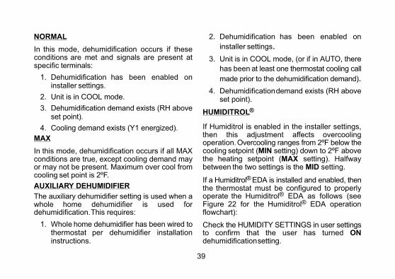
NORMAL
In this mode, dehumidification occurs if theseconditions are met and signals are present atspecific terminals:
1. Dehumidification has been enabled oninstaller settings.
2. Unit is in COOL mode.
3. Dehumidification demand exists (RH aboveset point).
4. Cooling demand exists (Y1 energized).
MAX
In this mode, dehumidification occurs if all MAXconditions are true, except cooling demand mayor may not be present. Maximum over cool fromcooling set point is 2ºF.
AUXILIARY DEHUMIDIFIER
The auxiliary dehumidifier setting is used when awhole home dehumidifier is used fordehumidification. This requires:
1. Whole home dehumidifier has been wired tothermostat per dehumidifier installationinstructions.
2. Dehumidification has been enabled on
installer settings.
3. Unit is in COOL mode, (or if in AUTO, there
has been at least one thermostat cooling call
made prior to the dehumidification demand).
4. Dehumidification demand exists (RH aboveset point).
HUMIDITROL®
If Humiditrol is enabled in the installer settings,then this adjustment affects overcoolingoperation. Overcooling ranges from 2ºF below thecooling setpoint (MIN setting) down to 2ºF abovethe heating setpoint (MAX setting). Halfwaybetween the two settings is the MID setting.
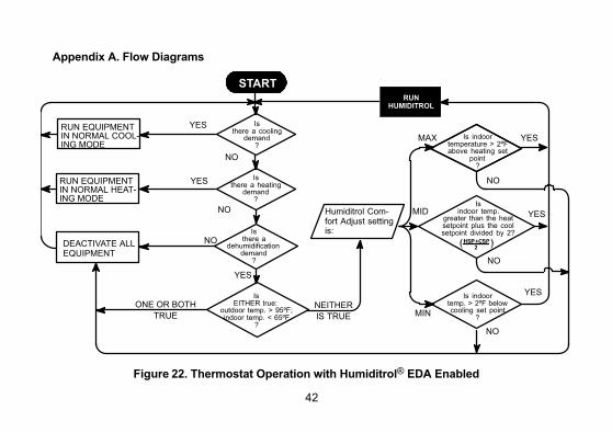
If a Humiditrol® EDA is installed and enabled, thenthe thermostat must be configured to properlyoperate the Humiditrol® EDA as follows (seeFigure 22 for the Humiditrol® EDA operationflowchart):
Check the HUMIDITY SETTINGS in user settingsto confirm that the user has turned ONdehumidification setting.
40
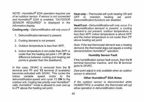
NOTE - Humiditrol® EDA operation requires useof an outdoor sensor. If sensor is not connectedand Humiditrol® EDA is enabled, “OUTDOORSENSOR REQUIRED” is displayed in theinformation display.
Cooling only—Dehumidification will only occur if:
1. Dehumidification demand is present.
2. Cooling demand is not present.
3. Outdoor temperature is less than 95ºF,
4. Indoor temperature is not cooler than 65ºF orcooler than the heating set point + 2ºF (IF thedifference between cooling and heating setpoints is greater than the deadband).
In this case, 24VAC is removed from the Dterminal and Y1 and Y2 terminal (if available)becomes activated with 24VAC. This cycles theindoor variable speed motor to thedehumidification speed and cycle Y2 ON to theoutdoor unit. Cooling has priority over Humiditrol®
calls. Humiditrol® mode is allowed to over cool upto 2ºF above the heating set point.
Heat only—Thermostat will cycle heating ON andOFF to maintain heating set point.Dehumidification functions are disabled.
Heat/Cool—Dehumidification will only occur if adehumidification demand is present, a coolingdemand is not present, outdoor temperature isless than 95ºF, indoor temperature is above 65ºFand the indoor temperature is not cooler than 2ºFabove heating set point.
Note: If the last thermostat demand was a heatingdemand, the thermostat does not require a coolingdemand before Humiditrol® operation.
Humidity Sensor Fault
If the humidification sensor fault occurs, then the Hterminal becomes inactive, and the D terminalgoes to 24VAC.
Dew point adjust is only available when an outdoorsensor is attached.
Other Humiditrol® EDA Notes
If the outdoor sensor is disconnected whileHUMIDITROL is enabled, the thermostat will notallow operation in dehumidification mode.
41
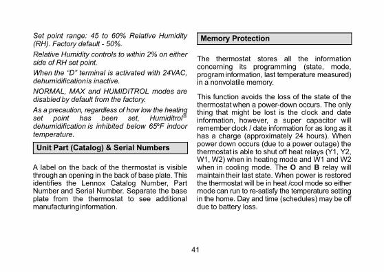
Set point range: 45 to 60% Relative Humidity(RH). Factory default - 50%.
Relative Humidity controls to within 2% on eitherside of RH set point.
When the “D” terminal is activated with 24VAC,dehumidification is inactive.
NORMAL, MAX and HUMIDITROL modes aredisabled by default from the factory.
As a precaution, regardless of how low the heatingset point has been set, Humiditrol®
dehumidification is inhibited below 65ºF indoortemperature.
Unit Part (Catalog) & Serial Numbers
A label on the back of the thermostat is visiblethrough an opening in the back of base plate. Thisidentifies the Lennox Catalog Number, PartNumber and Serial Number. Separate the baseplate from the thermostat to see additionalmanufacturing information.
Memory Protection
The thermostat stores all the informationconcerning its programming (state, mode,program information, last temperature measured)in a nonvolatile memory.
This function avoids the loss of the state of thethermostat when a power-down occurs. The onlything that might be lost is the clock and dateinformation, however, a super capacitor willremember clock / date information for as long as ithas a charge (approximately 24 hours). Whenpower down occurs (due to a power outage) thethermostat is able to shut off heat relays (Y1, Y2,W1, W2) when in heating mode and W1 and W2when in cooling mode. The O and B relay willmaintain their last state. When power is restoredthe thermostat will be in heat /cool mode so eithermode can run to re-satisfy the temperature settingin the home. Day and time (schedules) may be offdue to battery loss.
42
Appendix A. Flow Diagrams
MIN
MID
MAX
YES
NO
YES
NO
Is indoortemp. > 2ºF belowcooling set point
?
Isindoor temp.
greater than the heatsetpoint plus the coolsetpoint divided by 2?
Is indoortemperature > 2ºFabove heating set
point?
YES
YES
NO
NO
NO
NO
YES
ONE OR BOTH
TRUE
NEITHER
IS TRUE
Isthere a cooling
demand?
Isthere a
dehumidificationdemand
?
DEACTIVATE ALLEQUIPMENT
RUN EQUIPMENTIN NORMAL HEATING MODE
RUN EQUIPMENTIN NORMAL COOLING MODE
IsEITHER true:
outdoor temp. > 95ºF;indoor temp. < 65ºF
?
Humiditrol Comfort Adjust settingis:
RUNHUMIDITROL
START
Isthere a heating
demand?
YES
Figure 22. Thermostat Operation with Humiditrol® EDA Enabled

43
Appendix B. Diagnostic Information
ErrorCode
ScreenText
Priority0:high
1:middle2:low
MessageType
Condition System ActionAction to Clear /Recovery Condition
4
high temperatureprotection
0 critical
High temperature protection when outdoor ambienttemperature exceeds 96°F(35.6°C)
All stages of heat are turned offby safety relay.
This error is displayed on notification screen.
Once temperaturedrops below 96°F(35.6°C), the systemresume operation.
5temperaturesensor error
0 critical
Local temperature sensor is out of range -40°Fto 158°F
There is a finite difference between main thermistor and sub-thermistor which is greater than5°F.
Indoor temp is displayed as "--"on the home screen. This willSTOP all temperature relatedoperation.
All stages of heat are turned offby safety relay.
This error is displayed on notification screen.
Either thermostat willhave to be replace orif the sensor returns tonormal operatingrange, the error message will automaticallyclear and the systemwill resume operation.
7memoryerror
0 criticalEEPROM error(Power ON)
System will restore using to Energy Star defaults and resumeoperations.
This error is displayed on notification screen. Thermostat will need
to be replace.
8memoryerror
0 critical EEPROM error (Operating)
System will operate in normalmode operation until power off.
This error is displayed in notification screen.
44
ErrorCode
ScreenText
Priority0:high
1:middle2:low
MessageType
Condition System ActionAction to Clear /Recovery Condition
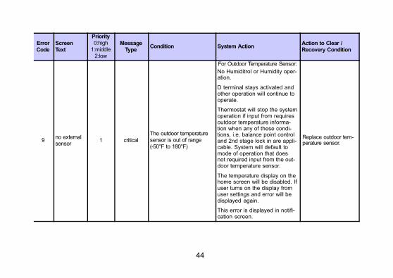
9no externalsensor
1 critical
The outdoor temperaturesensor is out of range(-50°F to 180°F)
For Outdoor Temperature Sensor:
No Humiditrol or Humidity operation.
D terminal stays activated andother operation will continue tooperate.
Thermostat will stop the systemoperation if input from requiresoutdoor temperature information when any of these conditions, i.e. balance point controland 2nd stage lock in are applicable. System will default tomode of operation that doesnot required input from the outdoor temperature sensor.
The temperature display on thehome screen will be disabled. Ifuser turns on the display fromuser settings and error will bedisplayed again.
This error is displayed in notification screen.
Replace outdoor temperature sensor.
45
Action to Clear /Recovery Condition
System ActionConditionMessage
Type
Priority0:high
1:middle2:low
ScreenText
ErrorCode
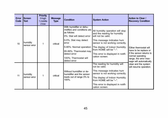
10humiditysensor error
1 critical
With humidifier or dehumidifier) and conditions areas follows:
0%: Stat will detect error
0-5%: Stat may detecterror
5-95%: Normal operation
95-99%: Thermostat maydetect error
100%: Thermostat willdetect error
All humidity operation will stopand the reading for humiditywill not be valid.
This message indicates humsensor is not working correctly.
The display of Indoor Humidityfrom HOME will be "--".
This error is displayed in notification screen.
Either thermostat willhave to be replace orif the sensor returns tonormal operatingrange, the error message will automaticallyclear and the systemwill resume operation.
11humiditysensor error
1 critical
Without humidifier or dehumidifier and the sensorreads out of range 0% to100%.
The reading for humidity willnot be valid.
This message indicates humsensor is not working correctly.
The display of Indoor Humidityfrom HOME will be "--".
This error is displayed in notification screen.

46
Action to Clear /Recovery Condition
System ActionConditionMessage
Type
Priority0:high
1:middle2:low
ScreenText
ErrorCode
N/Areplace media filter
2 reminder Media Filter
Displayed in notification screen.Pressing done buttonwill clear the reminder.
N/Areplace UVlamp
2 reminder UV Lamp
N/Areplace humidity pad
2 reminder Humidity Pad
N/A
routine system check-up
2 reminder Routine system check up
N/A
replacemetal insertfor pure air
2 reminder Metal Insert for Pure Air
N/Ausereditable
2 reminder custom reminder1
N/Ausereditable
2 reminder custom reminder2

47
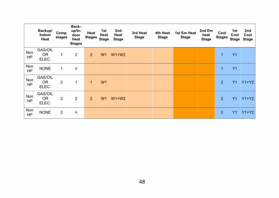
Appendix C. Supported Configurations
This thermostat support air conditioner and heat pump systems with one or two speed compressors. Italso supports dual-fuel and Humiditrol accessory. For all possible configuration see table below.
Backup/Indoor
Heat
Comp.stages
Backup/In
doorHeat
Stages
HeatStages
1stHeat
Stage
2ndHeat
Stage
3rd HeatStage
4th HeatStage
1st Em HeatStage
2nd Emheat
Stage
CoolStages
1stCool
Stage
2ndCool
Stage
HP GAS/OIL 1 1 2 Y1 W1 W1 1 Y1
HP GAS/OIL 1 2 3 Y1 W1 W1+W2 W1 W1+W2 1 Y1
HP NONE 1 0 1 Y1 1 Y1
HP GAS/OIL 2 1 3 Y1 Y1+Y2 W1 W1 2 Y1 Y1+Y2
HP GAS/OIL 2 2 4 Y1 Y1+Y2 W1 W1+W2 W1 W1+W2 2 Y1 Y1+Y2
HP NONE 2 0 2 Y1 Y1+Y2 2 Y1 Y1+Y2
HP ELEC. 1 1 2 Y1 Y1+W1 W1 1 Y1
HP ELEC. 1 2 3 Y1 Y1+W1 Y1+W1+W2 W1 W1+W2 1 Y1
HP NONE 1 0 1 Y1 1 Y1
HP ELEC. 2 1 3 Y1 Y1+Y2 Y1+Y2+W1 W1 2 Y1 Y1+Y2
HP ELEC. 2 2 4 Y1 Y1+Y2 Y1+Y2+W1Y1+Y2+W
1+W2W1 W1+W2 2 Y1 Y1+Y2
HP NONE 2 0 2 Y1 Y1+Y2 2 Y1 Y1+Y2
NonHP
GAS/OILOR
ELEC.1 1 1 W1 1 Y1
48
Backup/Indoor
Heat
Comp.stages
Backup/In
doorHeat
Stages
HeatStages
1stHeat
Stage
2ndHeat
Stage
3rd HeatStage
4th HeatStage
1st Em HeatStage
2nd Emheat
Stage
CoolStages
1stCool
Stage
2ndCool
Stage
NonHP
GAS/OILOR
ELEC.1 2 2 W1 W1+W2 1 Y1
NonHP
NONE 1 0 1 Y1
NonHP
GAS/OILOR
ELEC.2 1 1 W1 2 Y1 Y1+Y2
NonHP
GAS/OILOR
ELEC.2 2 2 W1 W1+W2 2 Y1 Y1+Y2
NonHP
NONE 2 0 2 Y1 Y1+Y2

49
Appendix D. Installation Checklist
ItemNumber
Item Yes No
1 Is the thermostat level where mounted on the wall?
2Is the thermostat installed away from direct sunlight or discharge air vents?
3Has the thermostat been wired correctly based on the type ofequipment installed (air handler, outdoor unit and accessories?
4 Is the thermostat wiring secured tightly to the terminals?
5 Is the common wire (terminal C) connected?
6Has the System Test Mode located under the installer settingsbeen used to verify proper operation?

50
INDEX
C
Compressor Short Cycle Protection, 3
Custom Reminder, 34
D
Deadband, 25
Dealer Information, 25
Dehumidify, 38
Auxiliary Dehumidifier, 39
Humiditrol, 39
Max, 39
Normal, 39
Diagnostic Information, 43
Dimensions, 3
E
Energy Saving Defaults, 35
Enhanced Dehumidification Accessory, 12
F
Features, 3
H
Humidification Sensor Fault, 40
Humidify, 37
Dew Point Normal and Max, 37
Normal and Max, 37
Humidity Offset, 25
Humidity Setting, 34
I
Installation Checklist, 49
Installer Settings, 21
L
Low and High Balance Points, 22
M
Memory Protection, 41
51
Menu Screen, 21
O
Outdoor Sensor, 4, 22
Outdoor Temperature Sensor, 3
R
Reset Settings, 34
Residual Cool, 22
S
Screws, 2
Settings, 21
Smooth Set Back (SSR), 25
Smooth Set Back Stage 2 Lock Out, 25
Stage 1 Differential, 26
Stage 2 through 4 Differential, 26
Stage Delay Differentials, 26
Stage Delay Timer, 26
Supported Configurations, 47
System Setup, 22
System Test Modes, 35
T
Temperature Offset, 25
Terminal Designations, 11
Thermostat Installation, 6
U
Unit Part (Catalog) & Serial Numbers, 41
W
Wall Anchors, 2
Wiring Diagrams, 12, 13, 14, 15, 16, 17, 18, 19,20
Wiring Thermostat, 11
52
® U.S. Registered TrademarkModel: 13H14
507504-014/2015Supersedes 3/2015
©2015 Lennox Industries Inc.Dallas, Texas, USA