Installation and Service Manual - Fujitsu€¦ · ExternalI/OExpansionUnit forSPARCEnterprise...
182
External I/O Expansion Unit for SPARC Enterprise M4000/M5000/M8000/M9000 Servers Installation and Service Manual Part No.: E22742-01, Manual Code: C120-E329-07EN April 2011
Transcript of Installation and Service Manual - Fujitsu€¦ · ExternalI/OExpansionUnit forSPARCEnterprise...

External I/O Expansion Unitfor SPARC EnterpriseM4000/M5000/M8000/M9000 Servers
Installation and Service Manual
Part No.: E22742-01,Manual Code: C120-E329-07ENApril 2011

Copyright © 2007, 2011, Oracle and/or its affiliates. All rights reserved.FUJITSU LIMITED provided technical input and review on portions of this material.Oracle and/or its affiliates and Fujitsu Limited each own or control intellectual property rights relating to products and technology described in thisdocument, and such products, technology and this document are protected by copyright laws, patents, and other intellectual property laws andinternational treaties.This document and the product and technology to which it pertains are distributed under licenses restricting their use, copying, distribution, anddecompilation. No part of such product or technology, or of this document, may be reproduced in any form by any means without prior writtenauthorization of Oracle and/or its affiliates and Fujitsu Limited, and their applicable licensors, if any. The furnishings of this document to you does notgive you any rights or licenses, express or implied, with respect to the product or technology to which it pertains, and this document does not contain orrepresent any commitment of any kind on the part of Oracle or Fujitsu Limited, or any affiliate of either of them.This document and the product and technology described in this document may incorporate third-party intellectual property copyrighted by and/orlicensed from the suppliers to Oracle and/or its affiliates and Fujitsu Limited, including software and font technology.Per the terms of the GPL or LGPL, a copy of the source code governed by the GPL or LGPL, as applicable, is available upon request by the End User. Pleasecontact Oracle and/or its affiliates or Fujitsu Limited.This distribution may include materials developed by third parties.Parts of the product may be derived from Berkeley BSD systems, licensed from the University of California. UNIX is a registered trademark in the U.S. andin other countries, exclusively licensed through X/Open Company, Ltd.Oracle and Java are registered trademarks of Oracle and/or its affiliates. Fujitsu and the Fujitsu logo are registered trademarks of Fujitsu Limited.All SPARC trademarks are used under license and are registered trademarks of SPARC International, Inc. in the U.S. and other countries. Products bearingSPARC trademarks are based upon architectures developed by Oracle and/or its affiliates. SPARC64 is a trademark of SPARC International, Inc., usedunder license by Fujitsu Microelectronics, Inc. and Fujitsu Limited. Other names may be trademarks of their respective owners.United States Government Rights - Commercial use. U.S. Government users are subject to the standard government user license agreements of Oracleand/or its affiliates and Fujitsu Limited and the applicable provisions of the FAR and its supplements.Disclaimer: The only warranties granted by Oracle and Fujitsu Limited, and/or any affiliate of either of them in connection with this document or anyproduct or technology described herein are those expressly set forth in the license agreement pursuant to which the product or technology is provided.EXCEPT AS EXPRESSLY SET FORTH IN SUCH AGREEMENT, ORACLE OR FUJITSU LIMITED, AND/OR THEIR AFFILIATES MAKE NOREPRESENTATIONS OR WARRANTIES OF ANY KIND (EXPRESS OR IMPLIED) REGARDING SUCH PRODUCT OR TECHNOLOGY OR THISDOCUMENT, WHICH ARE ALL PROVIDED AS IS, AND ALL EXPRESS OR IMPLIED CONDITIONS, REPRESENTATIONS AND WARRANTIES,INCLUDING WITHOUT LIMITATION ANY IMPLIED WARRANTY OF MERCHANTABILITY, FITNESS FOR A PARTICULAR PURPOSE OR NON-INFRINGEMENT, ARE DISCLAIMED, EXCEPT TO THE EXTENT THAT SUCH DISCLAIMERS ARE HELD TO BE LEGALLY INVALID. Unlessotherwise expressly set forth in such agreement, to the extent allowed by applicable law, in no event shall Oracle or Fujitsu Limited, and/or any of theiraffiliates have any liability to any third party under any legal theory for any loss of revenues or profits, loss of use or data, or business interruptions, or forany indirect, special, incidental or consequential damages, even if advised of the possibility of such damages.DOCUMENTATION IS PROVIDED “AS IS” AND ALL EXPRESS OR IMPLIED CONDITIONS, REPRESENTATIONS AND WARRANTIES,INCLUDING ANY IMPLIED WARRANTY OF MERCHANTABILITY, FITNESS FOR A PARTICULAR PURPOSE OR NON-INFRINGEMENT, AREDISCLAIMED, EXCEPT TO THE EXTENT THAT SUCH DISCLAIMERS ARE HELD TO BE LEGALLY INVALID.
PleaseRecycle

Copyright © 2007, 2011, Oracle et/ou ses sociétés affiliées. Tous droits réservés.FUJITSU LIMITED a fourni et vérifié des données techniques de certaines parties de ce composant.Oracle et/ou ses sociétés affiliées et Fujitsu Limited détiennent et contrôlent chacune des droits de propriété intellectuelle relatifs aux produits ettechnologies décrits dans ce document. De même, ces produits, technologies et ce document sont protégés par des lois sur le copyright, des brevets,d’autres lois sur la propriété intellectuelle et des traités internationaux.Ce document, le produit et les technologies afférents sont exclusivement distribués avec des licences qui en restreignent l’utilisation, la copie, ladistribution et la décompilation. Aucune partie de ce produit, de ces technologies ou de ce document ne peut être reproduite sous quelque forme que cesoit, par quelque moyen que ce soit, sans l’autorisation écrite préalable d’Oracle et/ou ses sociétés affiliées et de Fujitsu Limited, et de leurs éventuelsbailleurs de licence. Ce document, bien qu’il vous ait été fourni, ne vous confère aucun droit et aucune licence, expresses ou tacites, concernant le produitou la technologie auxquels il se rapporte. Par ailleurs, il ne contient ni ne représente aucun engagement, de quelque type que ce soit, de la part d’Oracle oude Fujitsu Limited, ou des sociétés affiliées de l’une ou l’autre entité.Ce document, ainsi que les produits et technologies qu’il décrit, peuvent inclure des droits de propriété intellectuelle de parties tierces protégés parcopyright et/ou cédés sous licence par des fournisseurs à Oracle et/ou ses sociétés affiliées et Fujitsu Limited, y compris des logiciels et des technologiesrelatives aux polices de caractères.Conformément aux conditions de la licence GPL ou LGPL, une copie du code source régi par la licence GPL ou LGPL, selon le cas, est disponible surdemande par l’Utilisateur final. Veuillez contacter Oracle et/ou ses sociétés affiliées ou Fujitsu Limited.Cette distribution peut comprendre des composants développés par des parties tierces.Des parties de ce produit peuvent être dérivées des systèmes Berkeley BSD, distribués sous licence par l’Université de Californie. UNIX est une marquedéposée aux États-Unis et dans d’autres pays, distribuée exclusivement sous licence par X/Open Company, Ltd.Oracle et Java sont des marques déposées d’Oracle Corporation et/ou de ses sociétés affiliées. Fujitsu et le logo Fujitsu sont des marques déposées deFujitsu Limited.Toutes les marques SPARC sont utilisées sous licence et sont des marques déposées de SPARC International, Inc., aux États-Unis et dans d’autres pays. Lesproduits portant la marque SPARC reposent sur des architectures développées par Oracle et/ou ses sociétés affiliées. SPARC64 est une marque de SPARCInternational, Inc., utilisée sous licence par Fujitsu Microelectronics, Inc. et Fujitsu Limited. Tout autre nom mentionné peut correspondre à des marquesappartenant à d’autres propriétaires.United States Government Rights - Commercial use. U.S. Government users are subject to the standard government user license agreements of Oracleand/or its affiliates and Fujitsu Limited and the applicable provisions of the FAR and its supplements.Avis de non-responsabilité : les seules garanties octroyées par Oracle et Fujitsu Limited et/ou toute société affiliée de l’une ou l’autre entité en rapportavec ce document ou tout produit ou toute technologie décrits dans les présentes correspondent aux garanties expressément stipulées dans le contrat delicence régissant le produit ou la technologie fournis. SAUF MENTION CONTRAIRE EXPRESSÉMENT STIPULÉE DANS CE CONTRAT, ORACLE OUFUJITSU LIMITED ET LES SOCIÉTÉS AFFILIÉES À L’UNE OU L’AUTRE ENTITÉ REJETTENT TOUTE REPRÉSENTATION OU TOUTE GARANTIE,QUELLE QU’EN SOIT LA NATURE (EXPRESSE OU IMPLICITE) CONCERNANT CE PRODUIT, CETTE TECHNOLOGIE OU CE DOCUMENT,LESQUELS SONT FOURNIS EN L’ÉTAT. EN OUTRE, TOUTES LES CONDITIONS, REPRÉSENTATIONS ET GARANTIES EXPRESSES OU TACITES, YCOMPRIS NOTAMMENT TOUTE GARANTIE IMPLICITE RELATIVE À LA QUALITÉ MARCHANDE, À L’APTITUDE À UNE UTILISATIONPARTICULIÈRE OU À L’ABSENCE DE CONTREFAÇON, SONT EXCLUES, DANS LA MESURE AUTORISÉE PAR LA LOI APPLICABLE. Sauf mentioncontraire expressément stipulée dans ce contrat, dans la mesure autorisée par la loi applicable, en aucun cas Oracle ou Fujitsu Limited et/ou l’une oul’autre de leurs sociétés affiliées ne sauraient être tenues responsables envers une quelconque partie tierce, sous quelque théorie juridique que ce soit, detout manque à gagner ou de perte de profit, de problèmes d’utilisation ou de perte de données, ou d’interruptions d’activités, ou de tout dommageindirect, spécial, secondaire ou consécutif, même si ces entités ont été préalablement informées d’une telle éventualité.LA DOCUMENTATION EST FOURNIE « EN L’ÉTAT » ET TOUTE AUTRE CONDITION, DÉCLARATION ET GARANTIE, EXPRESSE OU TACITE, ESTFORMELLEMENT EXCLUE, DANS LA MESURE AUTORISÉE PAR LA LOI EN VIGUEUR, Y COMPRIS NOTAMMENT TOUTE GARANTIEIMPLICITE RELATIVE À LA QUALITÉ MARCHANDE, À L’APTITUDE À UNE UTILISATION PARTICULIÈRE OU À L’ABSENCE DECONTREFAÇON.


Contents
Preface xi
1. Overview 1–1
1.1 General Description 1–2
1.1.1 Chassis 1–4
1.1.2 Power Supply Units 1–5
1.1.2.1 AC Power 1–6
1.1.2.2 Fans 1–6
1.1.3 I/O Boats 1–7
1.2 Card Slots 1–9
1.2.1 Carriers 1–9
1.2.1.1 Carrier Slots 1–10
1.2.1.2 Dummy Cards 1–11
1.2.2 Link Kits 1–12
1.2.3 Cable Management 1–13
1.2.3.1 Minimum Bend Radius for Link Cables 1–15
1.2.3.2 Cable Management Unit 1–16
1.3 Carriers 1–17
1.3.1 Carrier Removal and Insertion 1–18
1.3.2 Card Locks 1–20
v

1.3.3 Tightening Sequence for Card Locks 1–21
1.3.3.1 Tightening Sequence for Wide Cards 1–22
1.3.3.2 Tightening Sequence for Narrow Cards 1–22
1.3.4 Examples of PCI Card Installation 1–23
1.3.4.1 Using Card Locks With Tall PCI Cards 1–25
1.3.4.2 Using Card Locks With Low and Very Low Height PCICards 1–26
1.3.4.3 Using Card Locks With Unusual PCI Card Shapes 1–27
1.3.5 PCI Card Mounting Problems 1–27
1.3.5.1 Tilted Cards 1–27
1.3.5.2 Hidden Problems 1–29
1.3.6 Carrier Keys 1–33
1.4 External I/O Expansion Unit Configurations 1–34
1.4.1 Single Boat Configuration 1–34
1.4.2 Dual Boat Configuration 1–35
1.5 LEDs 1–36
1.6 System Management 1–38
1.6.1 Maximum Temperatures in the External I/O Expansion Unit 1–39
1.7 Site Preparation 1–39
1.7.1 Physical Requirements 1–39
1.7.2 Electrical Requirements 1–40
1.8 Service Information 1–41
1.9 Electrostatic Discharge Precautions 1–43
2. Installing the External I/O Expansion Unit in a Rack 2–1
2.1 Tools 2–1
2.2 Installing the Mounting Brackets in a Rack 2–2
2.3 Installing the External I/O Expansion Unit in the Rack 2–7
2.4 Installing the Cable Management Unit 2–9
vi External I/O Expansion Unit for SPARC Enterprise Mx000 Servers Installation and Service Manual • April 2011

2.5 Installing the AC Cords 2–13
2.6 Installing the Link Kit 2–16
2.6.1 Installing the Optical Link Kit 2–17
2.6.2 Installing the Copper Link Kit 2–18
3. Working With PCI Cards 3–1
3.1 Installing a PCI Card 3–1
3.2 Replacing a PCI Card 3–9
3.3 Installing Cables for PCI Cards 3–16
4. Servicing and Replacing Components 4–1
4.1 Service Procedures Task Map 4–2
4.2 Identifying Firmware Versions 4–3
4.3 Replacing a Power Supply Unit 4–4
4.4 Powering Down a Link Before Service 4–6
4.4.1 The cfgadm -c disconnect Command 4–6
4.4.2 Example of the cfgadm -c disconnect Command 4–6
4.5 Preparing the Cable Plate for Service 4–7
4.6 Replacing a Carrier 4–9
4.7 Replacing a Link Cable 4–13
4.8 Replacing a Link Card in the Host Server 4–13
4.9 Replacing a Link Card in an I/O Boat 4–14
4.10 Installing a Second I/O Boat 4–16
4.11 Replacing an I/O Boat 4–19
4.11.1 Replacing a Boat in a Single Boat Configuration 4–19
4.11.2 Replacing a Boat in a Dual Boat Configuration 4–21
4.12 Replacing the External I/O Expansion Unit Chassis 4–24
4.12.1 Locating the New System Serial Number Label 4–24
4.12.2 Preparing the External I/O Expansion Unit 4–24
Contents vii

4.12.3 Moving the Bezel to the New Chassis 4–26
4.12.4 Installing the External I/O Expansion Unit in the Rack 4–30
4.13 Powering Up a Link After Service 4–33
4.13.1 The cfgadm -c configure Command 4–33
4.13.2 Example of the cfgadm -c configure Command 4–34
A. Specifications A–1
A.1 Physical Specifications A–2
A.2 Clearance for Service Access A–2
A.3 Environmental Specifications A–3
A.4 Power Source Requirements A–4
A.5 Acoustic Noise Emissions A–4
A.6 Agency Compliance Specifications A–5
B. External I/O Expansion Unit LED Status Indicators B–1
B.1 LED Locations B–2
B.2 LED States B–4
C. PCI Cards and Device Mapping C–1
C.1 Device Mapping C–1
C.2 Device Map Examples C–3
C.2.1 Device Map for PCI Express Cards C–3
C.2.2 Device Map for PCI-X Cards C–4
C.3 Software Commands for the External I/O Expansion Unit C–6
C.3.1 The ioxadm Command C–7
C.3.2 The show-devs Command C–8
C.3.3 The cfgadm Command C–11
C.3.4 The prtdiag Command C–12
D. Troubleshooting D–1
viii External I/O Expansion Unit for SPARC Enterprise Mx000 Servers Installation and Service Manual • April 2011

D.1 Using Hardware Symptoms to Troubleshoot Problems D–2
D.2 Using Manual Techniques of Fault Isolation to Diagnose Error MessagesD–4
D.2.1 Error Messages and Fault Managed Resource Identifiers D–4
D.2.2 I2C Failures D–6
D.2.2.1 I2C Fault Isolated to a Single FRU D–7
D.2.2.2 I2C Fault Spanning Multiple FRUs D–7
D.2.2.3 I2C Fault When Accessing the Link Card Installed in theHost D–11
D.2.3 Management Bus Failures D–12
D.2.4 Cable Removed or Power Loss D–13
D.2.5 Interrupt Signal Failures D–14
D.2.6 FRU Discovery Failures D–15
D.2.6.1 Signal Failure D–15
D.2.6.2 Boat Not Monitored D–16
D.2.6.3 Link Card Mode Failure D–17
D.2.6.4 Boat Location Failure D–17
D.2.7 Reported Failures on the Microcontroller D–19
D.2.7.1 Fan Controller Reset D–19
D.2.7.2 Fan Controller Timeout D–20
D.2.7.3 Bridge Controller Reset D–20
D.2.7.4 Bridge Controller Timeout D–21
Index Index–1
Contents ix

x External I/O Expansion Unit for SPARC Enterprise Mx000 Servers Installation and Service Manual • April 2011

Preface
This manual provides installation and service procedures for the External I/OExpansion Unit from Oracle and Fujitsu.
This document is written for technicians, system administrators, authorized serviceproviders, and users who have advanced experience troubleshooting and replacinghardware.
This chapter includes the following sections:
■ “External I/O Expansion Unit Documents” on page xi
■ “Text Conventions” on page xii
■ “Notes on Safety” on page xiii
■ “Documentation Feedback” on page xiii
External I/O Expansion Unit DocumentsAll documents for your External I/O Expansion Unit are available online at thefollowing locations:
■ Oracle documents:
http://download.oracle.com/docs/cd/E19322-01/index.html
■ Fujitsu documents:
http://www.fujitsu.com/sparcenterprise/manual/
■ Sun Oracle software-related manuals (Oracle Solaris OS, and so on):
http://www.oracle.com/technetwork/documentation/index.html
xi

Text ConventionsThis manual uses the following fonts and symbols to express specific types ofinformation.
External I/O Expansion Unit Documents
External I/O Expansion Unit Installation and Service Manual
External I/O Expansion Unit Product Notes
External I/O Expansion Unit Safety and Compliance Guide
Fonts/symbols Meaning Example
AaBbCc123 What you type, when contrastedwith on-screen computer output.This font represents the example ofcommand input in the frame.
XSCF> adduser jsmith
AaBbCc123 The names of commands, files, anddirectories; on-screen computeroutput.This font represents the example ofcommand input in the frame.
XSCF> showuser -PUser Name: jsmithPrivileges: useradm
auditadm
Italic Indicates the name of a referencemanual
See the SPARC EnterpriseM3000/M4000/M5000/M8000/M9000 Servers XSCF User’s Guide.
" " Indicates names of chapters,sections, items, buttons, or menus
See Chapter 2, "System Features."
xii External I/O Expansion Unit for SPARC Enterprise Mx000 Servers Installation and Service Manual • April 2011
Notes on SafetyRead the following documents thoroughly before using or handling any External I/OExpansion Unit.
■ External I/O Expansion Unit Safety and Compliance Guide.
■ SPARC Enterprise M3000/M4000/M5000/M8000/M9000 Servers Important Legal andSafety Information
Documentation FeedbackIf you have any comments or requests regarding this document, go to the followingweb sites.
■ For Oracle users:
http://www.oraclesurveys.com/se.ashx?s=25113745587BE578
■ For Fujitsu users:
http://www.fujitsu.com/global/contact/computing/sparce_index.html
Preface xiii

xiv External I/O Expansion Unit for SPARC Enterprise Mx000 Servers Installation and Service Manual • April 2011

CHAPTER 1
Overview
The External I/O Expansion Unit provides a host server with additional slots for PCIcards.
■ The single I/O boat configuration provides six slots for I/O cards.
■ The optional two I/O boat configuration (FIGURE 1-1) provides twelve slots.
This chapter contains the following topics:
■ Section 1.1, “General Description” on page 1-2
■ Section 1.2, “Card Slots” on page 1-9
■ Section 1.3, “Carriers” on page 1-17
■ Section 1.4, “External I/O Expansion Unit Configurations” on page 1-34
■ Section 1.5, “LEDs” on page 1-36
■ Section 1.6, “System Management” on page 1-38
■ Section 1.7, “Site Preparation” on page 1-39
■ Section 1.8, “Service Information” on page 1-41
■ Section 1.9, “Electrostatic Discharge Precautions” on page 1-43
1-1

FIGURE 1-1 External I/O Expansion Unit, Front and Rear Views
1.1 General DescriptionFIGURE 1-2 shows the major units for the External I/O Expansion Unit, which aredescribed separately in this chapter.
Note – All slot numbers run from left to right, regardless of whether you areviewing the front or the back of the External I/O Expansion Unit. At the front of theExternal I/O Expansion Unit, the power supplies are numbered from left to right.I/O boats at the rear of the External I/O Expansion Unit are also numbered from leftto right.
Figure Legend
1 Front view
2 Rear view
1
2
1-2 External I/O Expansion Unit for SPARC Enterprise Mx000 Servers Installation and Service Manual • April 2011

FIGURE 1-2 Major Units for the External I/O Expansion Unit, Top View
Figure Legend
1 Chassis 6 I/O boat 1
2 Power Supply Unit 1 7 Internal AC cable
3 Power Supply Unit 0 8 Cable management unit (One of two types is included. Type8a routes cables to both sides of a rack. Type 8b routescables only the right side of a rack.)
4 Centerplane 9 Link kit (One of two types is included. 9a is the copper linkkit. 9b is the optical link kit.)
5 I/O boat 0
32
5
6
7
1
9a4
9b
8a 8b
Chapter 1 Overview 1-3
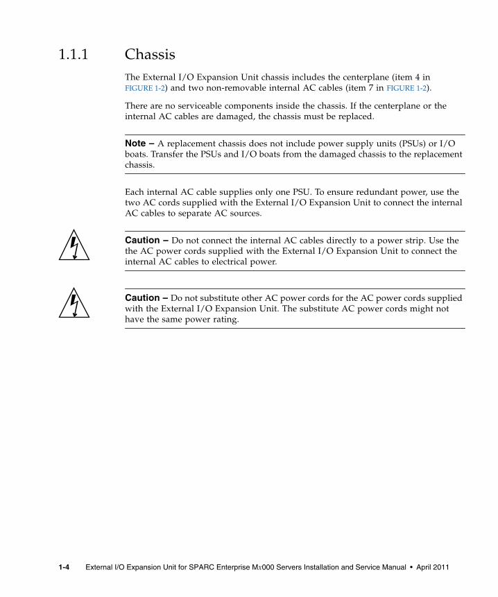
1.1.1 ChassisThe External I/O Expansion Unit chassis includes the centerplane (item 4 inFIGURE 1-2) and two non-removable internal AC cables (item 7 in FIGURE 1-2).
There are no serviceable components inside the chassis. If the centerplane or theinternal AC cables are damaged, the chassis must be replaced.
Note – A replacement chassis does not include power supply units (PSUs) or I/Oboats. Transfer the PSUs and I/O boats from the damaged chassis to the replacementchassis.
Each internal AC cable supplies only one PSU. To ensure redundant power, use thetwo AC cords supplied with the External I/O Expansion Unit to connect the internalAC cables to separate AC sources.
Caution – Do not connect the internal AC cables directly to a power strip. Use thethe AC power cords supplied with the External I/O Expansion Unit to connect theinternal AC cables to electrical power.
Caution – Do not substitute other AC power cords for the AC power cords suppliedwith the External I/O Expansion Unit. The substitute AC power cords might nothave the same power rating.
1-4 External I/O Expansion Unit for SPARC Enterprise Mx000 Servers Installation and Service Manual • April 2011

1.1.2 Power Supply UnitsThe External I/O Expansion Unit has two power supply units (PSUs) forredundancy. See FIGURE 1-3.
Each PSU includes an integral fan.
FIGURE 1-3 Power Supply Unit
Figure Legend
1 PSU 5 Fan
2 Handle locking screw 6 Caution labels
3 Handle 7 PSU slot 0
4 AC switch 8 PSU slot 1
1
234
5
7
8
6
Chapter 1 Overview 1-5

1.1.2.1 AC Power
The PSU slots are powered through internal AC cables that extend out of the rear ofthe chassis (item 7 in FIGURE 1-2).
The PSUs do not share AC current. Connect both internal AC cables to AC power.
The internal AC cable for a PSU is the cable terminating nearest that PSU slot.
The PSUs should be connected to two independent external AC power sources sothat service will not be interrupted if one AC power source fails.
1.1.2.2 Fans
A fan is located in the front of each PSU. If one fan fails, the remaining fan suppliesenough air to cool two I/O boats.
Note – The fan might turn on when you insert a PSU into the External I/OExpansion Unit. This is normal behavior if you are installing a second PSU while thefirst PSU is powered on. The fan receives DC power through the centerplane.
1-6 External I/O Expansion Unit for SPARC Enterprise Mx000 Servers Installation and Service Manual • April 2011

1.1.3 I/O BoatsThe External I/O Expansion Unit can contain up to two I/O boats (FIGURE 1-4).
FIGURE 1-4 I/O Boat
There are two types of I/O boat, PCI-X and PCI Express. PCI cards are notinterchangeable between the two types of boats.
■ The PCI-X I/O boat accepts PCI-X cards and some older types of PCI cards.
■ The PCI Express I/O boat accepts PCI Express cards up to x8 lanes wide. PCIExpress x16 cards do not fit in this boat.
Figure Legend
1 I/O boat 5 Boat slot 0
2 Captive screws 6 Boat slot 1
3 Link card carrier (slot 0) 7 Caution labels
4 PCI card carriers (slots 1-6)
1
3
4
5
62
7
Chapter 1 Overview 1-7

FIGURE 1-5 PCI-X and PCI Express I/O Boat Layouts, Compared
A PCI-X I/O boat is shown on the left side of FIGURE 1-5. This boat has six PCI-Xsockets and one link socket.
A PCI Express I/O boat is shown on the right side. There are six PCI Express socketsand one link socket.
All PCI card data passes through the link card in the I/O boat.
A boat slot accepts either type of I/O boat.
When you run system diagnostics, the switches and bridges are displayed in theoutput of OpenBoot PROM probing. However, the link cards themselves neverappear during OpenBoot PROM probing. For examples of OpenBoot PROM output,see Appendix C.
Note – A bridge is a device that converts PCI Express and PCI-X signal formats andconnects multiple busses to a single bus. A switch is a device that connects multiplebusses to a single bus, without converting the signals to another format.
PCI-X I/O boat
6 PCI-X slots
32 lane switch
PCI-E I/O boat
32 lane switch
32 laneswitch
32 laneswitchBridge Bridge Bridge
Link
0
Slot
1
Slot
2
Slot
3
Slot
4
Slot
5
Slot
6
6 PCI-E slots
Link
0
Slot
1
Slot
2
Slot
3
Slot
4
Slot
5
Slot
6
6 PCI Express slots
PCI Express I/O boat
1-8 External I/O Expansion Unit for SPARC Enterprise Mx000 Servers Installation and Service Manual • April 2011

1.2 Card SlotsThe card slots have the following characteristics:
■ An I/O boat has seven card slots. Slot numbers 0 through 6 are counted from leftto right.
■ Slot 0 is reserved for the link card. Slot 0 is the first slot in the left side of the I/Oboat. For information about link cards, see Section 1.2.2, “Link Kits” on page 1-12.
■ Slots 1-6 are for PCI cards. (PCI cards are sometimes known as host adapters orhost bus adapters.)
■ PCI card slots are hot-pluggable.
■ PCI-X and PCI Express sockets (FIGURE 1-5) are incompatible in length and height.Installing a PCI-X or PCI Express card in the wrong type of I/O boat will damagethe card and the connector in the carrier slot.
■ The PCI Express I/O boat supports up to x8 card sockets. PCI Express x16 cardsare not supported in the PCI Express I/O boat.
Note – Graphics cards are not supported.
Caution – Do not insert a x16 PCI Express card in an I/O boat. The x16 cardconnector is too large for the x8 card socket and will damage the socket.
1.2.1 CarriersAll PCI cards in the External I/O Expansion Unit are mounted on carriers(FIGURE 1-25). Carriers control RFI emissions and maintain the proper flow of airthrough the External I/O Expansion Unit.
The front of each carrier is labelled with its slot number (PCIX 1 or PCIE 1, and soforth).
Note – Slot 0 is reserved for the link card. This slot is marked LINK 0.
There is only one type of carrier design used in the External I/O Expansion Unit. Thesame carrier fits all slots in both types of PCI-X and PCI Express boats. Carriers arephysically keyed to fit only specific slot numbers. The keys can be adjusted for otherslots as needed.
Chapter 1 Overview 1-9

Caution – If you install a PCI card when the External I/O Expansion Unit isrunning, be prepared to complete the installation within two minutes or so. If youleave a carrier slot empty, the External I/O Expansion Unit might overheat.
New carriers include dummy cards. The dummy cards help the carriers to stay inplace and to control the passage of air through the I/O boat. For information aboutdummy cards, see Section 1.2.1.2, “Dummy Cards” on page 1-11.
1.2.1.1 Carrier Slots
There are seven carriers in each I/O boat (FIGURE 1-6). Carriers can be adjusted to fitvarious sizes and shapes of PCI cards. Link cards use the same type of carrier.
■ Carrier slot 0 is always used for the link card.
■ Carrier slots 1 through 6 are used for PCI cards.
FIGURE 1-6 PCI Carrier
Figure Legend
1 Carrier handle
2 Carrier locking screw
1-10 External I/O Expansion Unit for SPARC Enterprise Mx000 Servers Installation and Service Manual • April 2011

1.2.1.2 Dummy Cards
New carriers are shipped with dummy cards (FIGURE 1-7).
There are two types of dummy card, PCI-X and PCI Express. (The PCI Express cardmight be labelled “PCI-E”.) Note that there are differences in their edge connectors.
FIGURE 1-7 Dummy Cards
Note – Be certain that the dummy cards are fully seated. This action minimizes thevibration of unused carriers in the I/O boat slots.
The service labels (not shown in FIGURE 1-7) on the dummy cards include simplifiedinstructions for removing and installing PCI cards.
Figure Legend
1 PCI Express version
2 PCI-X version
PCI-E
PCI-X
Chapter 1 Overview 1-11

Caution – The two types of dummy cards are not interchangeable. If you replace aPCI card with a dummy card, be sure that you use the right type of dummy card. Thedifferences in edge connectors on the dummy cards (FIGURE 1-7) are enough todamage the PCI card socket on the I/O boat.
1.2.2 Link KitsOne link kit is required for each I/O boat.
A link kit includes two link cards. One link card goes into the host server. The otherlink card goes into the I/O boat. The link cards are physically identical.
Two link options are available, a copper link kit and an optical link kit (FIGURE 1-8).
■ The copper link kit has one bidirectional cable. A low-profile bracket is includedso a link card can be used in a host that has low-profile I/O card slots.
■ The optical link kit has two unidirectional cables.
FIGURE 1-8 Link Kits
Figure Legend
1 Copper link kit
2 Optical link kit
1-12 External I/O Expansion Unit for SPARC Enterprise Mx000 Servers Installation and Service Manual • April 2011

Slot 0 in each I/O boat is the dedicated link card slot. Use slot 0 only for the linkcard.
1.2.3 Cable ManagementA cable management unit attaches to the rear of the system rack. There are two typesof cable management units.
■ Some racks allow the routing of cables along both sides of the rack. The type Acable plate (FIGURE 1-9) supports cable routing along both the left and right sidesof the rack.
■ Some racks allow routing of cables only along the right side of the rack. The typeB cable plate (FIGURE 1-10) is optimized for cable routing along the right side of therack.
Chapter 1 Overview 1-13

FIGURE 1-9 Cable Management Unit (Type A) for Routing Cables to Both Sides of theRack
Figure Legend
1 Type A cable plate
2 Support brackets
3 Cable plate locking screws
1
2
23
3
1-14 External I/O Expansion Unit for SPARC Enterprise Mx000 Servers Installation and Service Manual • April 2011

FIGURE 1-10 Cable Management Unit (Type B) for Routing Cables Only to the Right Side ofa Rack
Note – If the PSU1 power cable does not reach the rack power distribution unit,route the cable on the left side of the rack.
1.2.3.1 Minimum Bend Radius for Link Cables
The link cables might be damaged if they are coiled too tightly.
■ The minimum bend radius for the copper link cable is 1.85 in./47 mm.
■ The minimum bend radius for optical link cables is 1.8 in./46 mm.
Figure Legend
1 Type B cable plate
2 Support brackets
3 Cable plate locking screws
1
2
23
3
Chapter 1 Overview 1-15

Caution – Coiling the link cables with a smaller bend radius than listed above willbreak the cables.
1.2.3.2 Cable Management Unit
The cable management unit contains two support brackets and a cable plate.
The support brackets attach with screws to the rear of the system rack. The cableplate rests on the support brackets.
The cable plate has two positions (FIGURE 1-11).
■ In the normal position, the cable plate rests on the support brackets.
■ In the raised position, the cable plate rests slightly above the support brackets.This position provides clearance for you to remove and replace an I/O boat.
FIGURE 1-11 Cable Plate (Side Views of Normal and Service Positions)
1.3 CarriersIn the I/O boat, all PCI cards are mounted on carriers. When you insert the carrierand card into the boat and push the carrier handle into the closed position, thecarrier mechanism automatically seats the PCI card.
FIGURE 1-12 shows a carrier with an attached PCI card.
Figure Legend
1 Cable plate in the normal position (lowered)
2 Cable plate in the service position (raised)
3 Cable plate locking screw
12
3
1-16 External I/O Expansion Unit for SPARC Enterprise Mx000 Servers Installation and Service Manual • April 2011

Note – The service life of a carrier is at least 100 PCI card insertions. To avoidpremature failure of the carrier, do not repeatedly open and close the carrier morethan is necessary to familiarize yourself with its operation.
FIGURE 1-12 Carrier
FIGURE 1-13 shows the details of a typical carrier.
Figure Legend
1 PCI card
2 Carrier
3 Carrier handle in unlocked position
1
2
3
Chapter 1 Overview 1-17

FIGURE 1-13 Carrier Features
1.3.1 Carrier Removal and InsertionA carrier operates by raising or lowering a PCI card into or out of a card socket. Thevertical movement is approximately 0.4 in./10 mm.
A small metal latch (item 3 in FIGURE 1-14) is located at the front of the carrier. Thelatch locks the carrier handle in the extended position. This action prevents thecarrier plate and PCI card from falling and damaging the PCI slot connector as youpull the carrier unit out of the carrier slot.
Figure Legend
1 Carrier main body (metal) 4 Carrier handle
2 Carrier plate (plastic) 5 Card locks (see Section 1.3.2, “Card Locks” on page 1-20)
3 Carrier slot keyholes 6 Turnaround area for card lock
1
2
4
6
5
5
3
5
1-18 External I/O Expansion Unit for SPARC Enterprise Mx000 Servers Installation and Service Manual • April 2011

After the carrier is out of the I/O boat, you can unlock the carrier handle by pushingin the metal latch while pushing the carrier handle into its closed position. Note thatthe closed position provides more vertical clearance for a PCI card when you installor remove the PCI card.
When you insert the carrier into the I/O boat, the latch automatically unlocks itself.
FIGURE 1-14 Carriers
Caution – All carriers must contain either a PCI card or a dummy card to avoid lossof cooling air.
Figure Legend
1 Pull carrier handle to raise PCI card out of PCI slot socket
2 Push carrier handle and latch (3) to lower PCI card into socket
3 Latch
Chapter 1 Overview 1-19
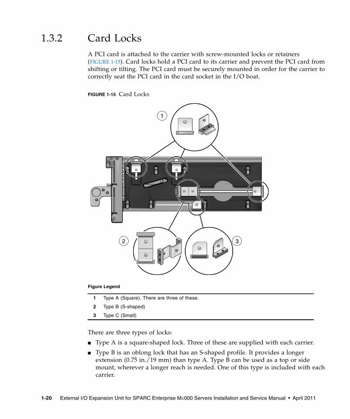
1.3.2 Card LocksA PCI card is attached to the carrier with screw-mounted locks or retainers(FIGURE 1-15). Card locks hold a PCI card to its carrier and prevent the PCI card fromshifting or tilting. The PCI card must be securely mounted in order for the carrier tocorrectly seat the PCI card in the card socket in the I/O boat.
FIGURE 1-15 Card Locks
There are three types of locks:
■ Type A is a square-shaped lock. Three of these are supplied with each carrier.
■ Type B is an oblong lock that has an S-shaped profile. It provides a longerextension (0.75 in./19 mm) than type A. Type B can be used as a top or sidemount, wherever a longer reach is needed. One of this type is included with eachcarrier.
Figure Legend
1 Type A (Square). There are three of these.
2 Type B (S-shaped)
3 Type C (Small)
1
2 3
1-20 External I/O Expansion Unit for SPARC Enterprise Mx000 Servers Installation and Service Manual • April 2011

■ Type C is a small quarter-round lock. It can support the bottom edge of a wide PCIcard, but only when the lock is at the far right side of its slot (the side farthestfrom the front of the carrier). For a narrow width card, use this lock only tosupport the side of the card. Do not use this lock to support the bottom edge of anarrow width card because the lock might interfere with the card socket in the I/Oboat. This lock fits only the bottom slot on the carrier. One of this type is suppliedwith each carrier.
One function of the locks is to secure the PCI card to the carrier. Another is to applya downward force to the top of the card to seat the card in the card socket when thecarrier is inserted into the I/O boat. In addition, the locks help prevent the card fromtilting so that card edge pins line up properly with the pins in the socket.
Because PCI card types are available in various sizes and shapes, you should choosea combination of card locks that is best suited to the size and shape of the PCI card.
1.3.3 Tightening Sequence for Card LocksTo fasten a PCI card to a carrier so that the card will seat reliably, tighten the cardlocks in the sequence shown in FIGURE 1-16 or FIGURE 1-17.
PCI card shapes and sizes can vary, so use the following instructions as suggestions,not as strict requirements.
■ If the PCI card is wide, use the tightening sequence shown in FIGURE 1-16. A widecard is one that can rest on the type C card lock (item 1 in FIGURE 1-16) when thecard lock is in its extreme right position.
■ If the PCI card is narrow, use the tightening sequence shown in FIGURE 1-17. Anarrow card is one that is too short to rest on the type C card lock when the cardlock is in its extreme right position.
Caution – If you move the type C card lock out of the extreme right position whilethe plastic part of the card lock is facing down, the PCI card will not seat properly,and the bottom of the card lock can damage the PCI card socket in the I/O boat. Ifyou move the type C card lock to the left at any time, always rotate the card lock sothat the plastic part faces either left or right.
Chapter 1 Overview 1-21

1.3.3.1 Tightening Sequence for Wide Cards
FIGURE 1-16 Card Lock Sequence for Wide Cards
● Rest the bottom edge of the PCI card on the type C card lock (number 1 inFIGURE 1-16) to ensure that the bottom of the PCI card is perfectly horizontal,then tighten the remaining card locks in the sequence shown.
1.3.3.2 Tightening Sequence for Narrow Cards
FIGURE 1-17 Card Lock Sequence for Narrow Cards
● Tighten the upper left card lock (number 1 in FIGURE 1-17), while ensuring thatthe card is perfectly horizontal. Then tighten the remaining card locks in thesequence shown, as applicable.
1
4
2 3
3
1
2
4
1-22 External I/O Expansion Unit for SPARC Enterprise Mx000 Servers Installation and Service Manual • April 2011

1.3.4 Examples of PCI Card InstallationFIGURE 1-15 shows the locks for a typical PCI card.
However, cards can be much wider or narrower, or taller or shorter. FIGURE 1-18,FIGURE 1-19, and FIGURE 1-20 show how cards can vary in height, width, and shape.
Note – The lock arrangements shown in these figures are suggestions and are notintended as requirements.
When installing a card, it might be necessary to swap locks from slot to slot in orderto find the best way to secure a PCI card to its carrier. Use TABLE 1-1 to select locksthat are best suited to your PCI card.
TABLE 1-1 Card and Lock Styles
Suggested Lock Type
PCI Card Shape Top Lock/Card Height Side Lock/Card Width Bottom Lock Example
Wide Type A (x2) Type A12 in./304 mmmaximum card width
Type C* FIGURE 1-18
Average width Type A (x2) Type A5.75 in./146 mmminimum card widthType B5.0 in./127 mmminimum card width
Type C† FIGURE 1-18
Narrow width Type A (1 or 2) Type A5.75 in./146 mmminimum card widthType B5.0 in./127 mmminimum card widthType C3.0 in./76 mmminimum card width
FIGURE 1-18
Very narrowwidth
Type A (1 or 2) Type B5.0 in./127 mmminimum card widthType C3.0 in./76 mmminimum card width
FIGURE 1-18
Tall Type A Type A or B Type C‡ FIGURE 1-18
Chapter 1 Overview 1-23

Low height Type A2.0 in./51 mmminimum card heightorType B1.25 in./31 mmminimum card height
Type A5.75 in./146 mmminimum card widthType B5.0 in./127 mmminimum card widthType C3.0 in./76 mmminimum card width
FIGURE 1-19
Very low heightand narrow
Type B1.25 in./31 mm minimum
Type C3.0 in./76 mm minimum
FIGURE 1-20
Irregular shape As needed As needed As needed** FIGURE 1-20
* Do not use the type C lock to support the bottom of a card if the lock will be in a location that causes the lock to interfere with thePCI card connector in the I/O boat.
† Do not use the type C lock to support the bottom of a card if the lock will be in a location that causes the lock to interfere with thePCI card connector in the I/O boat.
‡ Do not use the type C lock to support the bottom of a card if the lock will be in a location that causes the lock to interfere with thePCI card connector in the I/O boat.
** Do not use the type C lock to support the bottom of a card if the lock will be in a location that causes the lock to interfere with thecard connector.
TABLE 1-1 Card and Lock Styles (Continued)
Suggested Lock Type
PCI Card Shape Top Lock/Card Height Side Lock/Card Width Bottom Lock Example
1-24 External I/O Expansion Unit for SPARC Enterprise Mx000 Servers Installation and Service Manual • April 2011

1.3.4.1 Using Card Locks With Tall PCI Cards
FIGURE 1-18 Lock Arrangements for Wide and Narrow PCI cards
Figure Legend
1 Tall and wide card 2 type A on top, 1 type A on right, 1 type C on bottom of the PCI card
2 Tall and average width card 2 type A on top, 1 type A on right, 1 type C on bottom of the PCI card
3 Tall and narrow card 1 type A on top, 1 type A on right, 1 type C on lower right side of the PCI card
4 Tall and very narrow card 1 type A on top, 1 type B on right, 1 type C on lower right side of the PCI card
1
2
3
4
Chapter 1 Overview 1-25
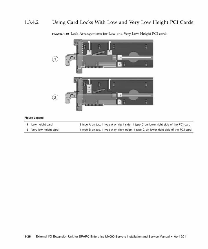
1.3.4.2 Using Card Locks With Low and Very Low Height PCI Cards
FIGURE 1-19 Lock Arrangements for Low and Very Low Height PCI cards
Figure Legend
1 Low height card 2 type A on top, 1 type A on right side, 1 type C on lower right side of the PCI card
2 Very low height card 1 type B on top, 1 type A on right edge, 1 type C on lower right side of the PCI card
1
2
1-26 External I/O Expansion Unit for SPARC Enterprise Mx000 Servers Installation and Service Manual • April 2011

1.3.4.3 Using Card Locks With Unusual PCI Card Shapes
FIGURE 1-20 Lock Arrangements for Unusually-Shaped Cards
1.3.5 PCI Card Mounting Problems
1.3.5.1 Tilted Cards
There are two common problems that involve PCI cards that turn at an angle whenmounted in PCI carriers.
■ The most common problem is that a PCI card can slip and tilt during seating whenyou do not apply enough pressure on a PCI carrier card lock when mounting thecard on the carrier.
■ A less common problem is that the bracket of a PCI card will bend when youapply too much pressure on a PCI carrier card lock when mounting the card on acarrier.
Figure Legend
1 Very low height and narrow width card 1 type B on top, 1 type C on right side of the PCI card
2 Irregularly-shaped card 1 type A and 1 type B on top, 1 type A on right side, 1 type C on lower rightside of the PCI card
1
2
Chapter 1 Overview 1-27

FIGURE 1-21 Excessive Force on a Lock Can Bend or Break the PCI Card
Here are some rules to avoid the tilting of PCI cards:
1. You must have at least one lock on top of the card. If the top of the card is too lowto accept a lock, the card cannot be used.
2. Find a lock to fit the top of the card and provide side support to prevent the cardfrom tilting. A tilted card (FIGURE 1-21) will not seat properly.
3. Support of the bottom of the card is not a major priority because the carrier plateitself provides some support for the bottom of the card.
4. Use only enough pressure to hold the lock against the PCI card. The bottom of thePCI card should stay parallel with the bottom of the carrier.
Figure Legend
1 Correct
2 Incorrect
1-28 External I/O Expansion Unit for SPARC Enterprise Mx000 Servers Installation and Service Manual • April 2011
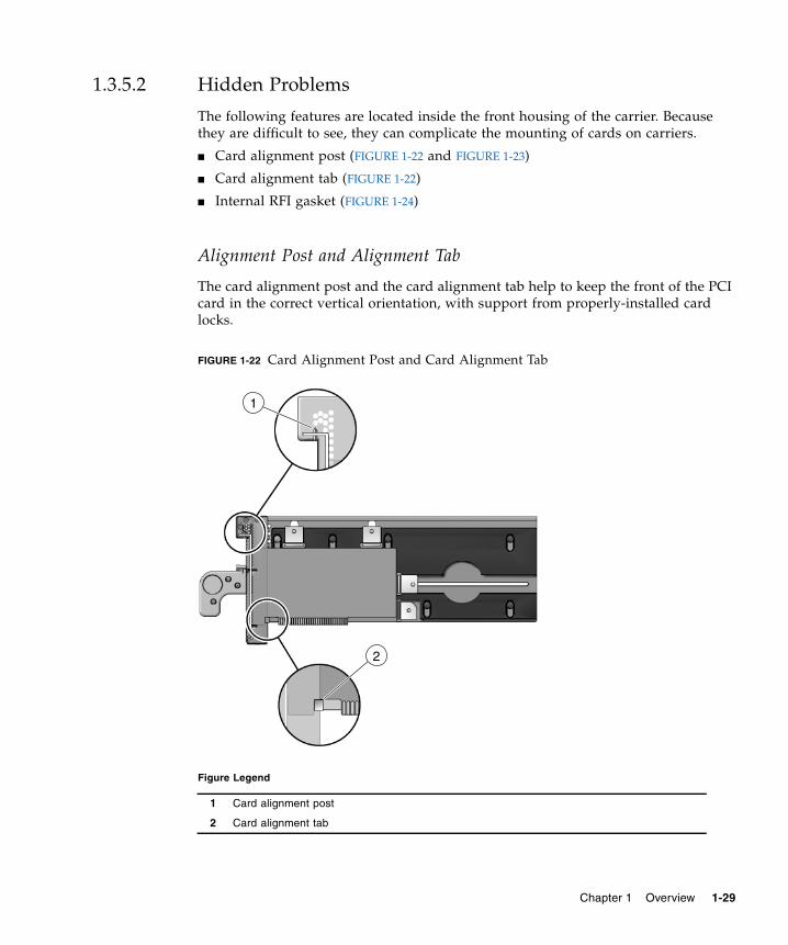
1.3.5.2 Hidden Problems
The following features are located inside the front housing of the carrier. Becausethey are difficult to see, they can complicate the mounting of cards on carriers.
■ Card alignment post (FIGURE 1-22 and FIGURE 1-23)
■ Card alignment tab (FIGURE 1-22)
■ Internal RFI gasket (FIGURE 1-24)
Alignment Post and Alignment Tab
The card alignment post and the card alignment tab help to keep the front of the PCIcard in the correct vertical orientation, with support from properly-installed cardlocks.
FIGURE 1-22 Card Alignment Post and Card Alignment Tab
Figure Legend
1 Card alignment post
2 Card alignment tab
2
1
Chapter 1 Overview 1-29

The post fits in a notch in the metal bracket of the PCI card (item 1 in FIGURE 1-22). Ifyou do not position the post in the notch, the card mounting bracket might bend, sothat the card lies at an angle on the carrier. The angle prevents the card from makingproper electrical contact with the socket in the I/O boat.
The tab (item 2 in FIGURE 1-22) fits in a notch at the bottom of the PCI card. The tabhelps to align the card when you install it in the carrier. (Note that some card typesmight not have the notch).
Note – The tab lifts the front of the card out of the card connector when you removethe carrier from the I/O boat. If you cannot use a type C lock (FIGURE 1-15) to supportthe bottom of the PCI card, the card alignment tab is the only point that can providesupport to lift the card out of the socket.
FIGURE 1-23 shows how the bracket fits over the card alignment post.
1-30 External I/O Expansion Unit for SPARC Enterprise Mx000 Servers Installation and Service Manual • April 2011

FIGURE 1-23 Card Alignment Post (Detail)
Figure Legend
1 Carrier front housing
2 Card alignment post
3 PCI card bracket
1
2
3
Chapter 1 Overview 1-31

Internal RFI Gasket
An RFI gasket is located inside the carrier housing, next to the card alignment post.(A smaller RFI gasket is located on the outside of the carrier housing.) When youinsert the PCI card into the carrier, be sure that the bottom of the metal card bracketdoes not scrape or loosen the bottom of the gasket (FIGURE 1-24).
The gasket material is flexible enough that you might not notice that the bracket hasdislodged the gasket. Remember to inspect the condition of this gasket before youinstall the carrier in the I/O boat.
FIGURE 1-24 Internal RFI Gasket
Figure Legend
1 PCI card
2 RFI gasket (extends to the bottom front of the PCI carrier)
3 Correct example: the RFI gasket lies flat
4 Incorrect example: the card bracket has hooked behind the RFI gasket
1
2
3
4
1-32 External I/O Expansion Unit for SPARC Enterprise Mx000 Servers Installation and Service Manual • April 2011

1.3.6 Carrier KeysEach carrier is keyed to a specific slot (FIGURE 1-25) in the I/O boat. The key is an M2screw on the top of each carrier. Each carrier slot (0 through 6) will accept only acarrier that has a key in the hole location for that slot.
FIGURE 1-25 Screw Hole Locations for the Carrier Slot Key
If you replace a carrier, install the key in the keyhole that corresponds to the slot thatyou use. A replacement carrier includes one key. It also includes an assortment oflabels. Affix the appropriate label (LINK 0, PCIE n, or PCIX n) to the front of thereplacement carrier for easy identification.
Figure Legend
1 Key (M2 screw)
2 Hole locations for carrier slots 0, 1, 2, 3 (front row)*
Hole locations for carrier slots 4, 5, 6, 7 (rear row)†
* Hole 0 and slot 0 are for the link card only.
† Hole 7 is reserved for future configurations.
1
2
Chapter 1 Overview 1-33

1.4 External I/O Expansion UnitConfigurationsThe External I/O Expansion Unit is available with one or two I/O boats. Two typesof link kits (copper and optical) are also available.
1.4.1 Single Boat ConfigurationThe base configuration for an External I/O Expansion Unit has a single boat, with afiller panel in the second boat bay. FIGURE 1-26 shows a host server and a baseExternal I/O Expansion Unit in the same rack.
A link card in the host server connects to a link card in the External I/O ExpansionUnit. One or two link cables connect the two link cards. (The cables are not shown toscale.)
The copper link kit includes a single 13 ft/4 m link cable.
The optical link kit includes two link cables. The link cables are either 33 ft/10 m or80 ft/25 m cables. Note that in FIGURE 1-26, the link cables are crossed so that theTransmit port (TX) of one link card connects to the Receive port (RX) of the other linkcard.
1-34 External I/O Expansion Unit for SPARC Enterprise Mx000 Servers Installation and Service Manual • April 2011

FIGURE 1-26 Optical Cables Connect TX Sockets to RX Sockets
1.4.2 Dual Boat ConfigurationThe dual boat configuration provides twelve I/O slots. Each of the I/O boats requiresits own link kit, so the host server must have two I/O slots available for this purpose.
Figure Legend
1 External I/O Expansion Unit
2 Host server
1
2
Chapter 1 Overview 1-35

Note – If you are installing a second boat in the External I/O Expansion Unit, bothboats must be connected to the same host server. Do not connect the second boat to adifferent server. The second boat can be connected to a different domain on the sameserver, but not to a domain on a different server.
Note – Do not daisy-chain two boats (connect a boat to another boat through linkcards). Daisy-chain configurations are not allowed.
1.5 LEDsLEDs are located on the front (FIGURE 1-27) and rear (FIGURE 1-28) of the chassis andon individual PSUs.
See Appendix B for information about interpreting LED states.
FIGURE 1-27 LEDs on the Front of the Chassis
Figure Legend
1 Chassis locate (LED and switch) 7 PSU0 DC power
2 Chassis fault/service required 8 PSU0 AC power
3 Chassis power 9 PSU1 ready to remove
1 2 3 4
5
6
7
8
9 10 11 12
1-36 External I/O Expansion Unit for SPARC Enterprise Mx000 Servers Installation and Service Manual • April 2011

Note – The Locate LED is a lighted push-button switch. When the flashing of itsLED has helped you to locate the External I/O Expansion Unit, turn off the LED bypressing the switch. Note that the LED does not turn off if you press less than 0.5seconds. You can also manually turn on the LED by pressing the button.
FIGURE 1-28 LEDs on the Rear of the Chassis
4 Chassis overtemp 10 PSU1 fault/locate
5 PSU0 ready to remove 11 PSU1 DC power
6 PSU0 fault/locate 12 PSU1 AC power
Figure Legend
1 Chassis locate (LED and switch) 8 I/O boat 1 ready to remove
2 Chassis fault/service required 9 I/O boat 1 fault/locate
3 Chassis power 10 I/O boat 1 DC power
4 Chassis overtemp 11 Link card data
Figure Legend
1 2 3 4
5 6 7
8 9 10
11
12
14
1311 12
Chapter 1 Overview 1-37

Note – On the optical link card, the LEDs for link card data and link cardmanagement are located next to the optical cable sockets. Although the LEDs arenear the sockets, they do not have any direct relationship to the sockets and are notintended to indicate the activity of the optical cable sockets.
1.6 System ManagementThe PSUs contain temperature sensors. The PSUs can shut down automatically ifthey detect an extreme temperature. The PSUs also have sensors for voltage andcurrent levels.
Temperature sensors are also located inside the I/O boats. FRU ID circuits are locatedon the link cards, the PSUs, the I/O boats, and on the chassis centerplane.Temperature data and FRU ID information is available on an I2C bus (Inter-IC bus)in the External I/O Expansion Unit and the link cards.
The service processor in the host system can monitor the I2C bus in the External I/OExpansion Unit. The service processor can power down the External I/O ExpansionUnit if parameters exceed maximum limits.
There is no service processor in the External I/O Expansion Unit itself.
The ioxadm command is available on the host system to display External I/OExpansion Unit sensor information and LED states. You can also use ioxadm tocontrol the Locate LEDs in the External I/O Expansion Unit and to power on or offFRUs in the External I/O Expansion Unit. Refer to the ioxadm (8) man page for moreinformation.
For examples of software commands, see Appendix C.
5 I/O boat 0 ready to remove 12 Link card management
6 I/O boat 0 fault/locate 13 Slot attention/locate (all PCI carriers)
7 I/O boat 0 DC power 14 Slot power (all PCI carriers)
Figure Legend
1-38 External I/O Expansion Unit for SPARC Enterprise Mx000 Servers Installation and Service Manual • April 2011

1.6.1 Maximum Temperatures in the External I/OExpansion UnitTABLE 1-1 summarizes the maximum temperatures for the External I/O ExpansionUnit. The table also includes error messages that the host might display if thesetemperatures exceed the maximum values. Two types of error messages might bedisplayed on the host console, Ereport (error report) and FMA (Fault ManagementArchitecture) messages.
1.7 Site PreparationThe following information summarizes installation requirements for the External I/OExpansion Unit.
For additional specifications and compliance information, see Appendix A.
1.7.1 Physical Requirements■ The External I/O Expansion Unit with the cable management unit attached is 17.3
in./440 mm wide and 39.4 in./1000 mm deep.
■ The movement of air through the External I/O Expansion Unit chassis is fromfront to back.
■ The External I/O Expansion Unit is four rack units tall (6.9 in./175 mm).
TABLE 1-2 Maximum Temperatures
Temperature Where Measured Comments
38˚C (100˚F) At the intake of the PSU Ereport: ereport.chassis.env.temp.otwFMA: fault.chassis.iox.env.temp.over-warn
54˚C (130˚F) Inside the PSU Ereport: ereport.chassis.env.temp.otfFMA: fault.chassis.iox.power.failNote: The PSU can turn itself off if its internal temperatureexceeds this value.
60˚C (140˚F) Inside the I/O boat Ereport: ereport.chassis.env.temp.otwFMA: fault.chassis.iox.env.temp.over-warn
65˚C (150˚F) Inside the I/O boat Ereport: ereport.chassis.env.temp.otfFMA: fault.chassis.iox.power.fail
Chapter 1 Overview 1-39

■ Service access to the External I/O Expansion Unit is from the front or rear. Themounting rails do not slide.
■ The choice of mounting location in a rack can be limited by the length of the linkcable:
■ The optical link kit includes either 33 ft/10 m or 80 ft/25 m cables. The ExternalI/O Expansion Unit can be located some distance from the host server rack.
■ The copper link kit includes a 13 ft/4 m cable.
■ The maximum weight of the External I/O Expansion Unit is approximately 81pounds (36.8 kg).
Caution – Mount the heaviest subassemblies at the lowest available opening in arack to minimize the precarious effects of a top-heavy system.
Note – Do not install another product between two External I/O Expansion Units ifthe product is short in height and shorter in depth than the External I/O ExpansionUnits. If there is little space between the upper and lower External I/O ExpansionUnits, there might not be enough space for your hands and arms to connect cables onthe rear of the product.
1.7.2 Electrical Requirements■ The maximum wattage per PCI card is 25 watts.
■ Two AC cords (supplied) must be used with the internal AC cables (FIGURE 1-2).
■ The supply voltage is 100 VAC to 240 VAC, 50-60 Hz.
■ The maximum power rating of External I/O Expansion Unit is 600 watts.
1-40 External I/O Expansion Unit for SPARC Enterprise Mx000 Servers Installation and Service Manual • April 2011

1.8 Service InformationService and installation information is also available on service labels that are locatedon the External I/O Expansion Unit top cover and on the dummy cards that areshipped with new carriers.
TABLE 1-3 Service Information Summary
Topic Comments
Access • Service access to the External I/O Expansion Unit is from thefront or rear of the unit.
• The top cover is removable.
Air flow • Air flow in the External I/O Expansion Unit is from front toback.
• Fans are located in the power supply units. There are noseparate fans or fan trays.
• The PSU and I/O boat slots have pivoting metal flaps that dropdown to close the slots when a PSU or I/O boat is removed.This prevents the loss of cooling air.
Mounting brackets The External I/O Expansion Unit is mounted on fixed brackets.Sliding brackets are not available for this product.
PCI card installation • To avoid overheating of the External I/O Expansion Unit, cardsshould be installed as quickly as possible.
• To prepare yourself to install a card within one or two minutes,see Section 1.3, “Carriers” on page 1-17.
PCI cable removal • When removing cables such as LAN cables, if you havedifficulty unlatching the connector, press the latch with aflathead screwdriver to remove the cable.
AC cables and cords • The internal AC cables (FIGURE 1-2) are not removable. If theyare damaged, replace the chassis.
• Each internal AC cable connects to only one PSU. Connect bothAC cables to AC power to ensure that both PSUs areoperational.
• The internal AC cables are not connected directly to AC voltage.Use the AC power cords to connect the internal AC cables to ACvoltage.
• Do not use AC cables designed for other products with theExternal I/O Expansion Unit.
Chapter 1 Overview 1-41

Link cables • The optical version of the link kit includes two unidirectionalcables. The ends of the cables are marked TX and RX (transmitand receive, respectively).
• The copper link kit has one cable. The connector is designed in away such that it cannot be connected upside down.
Jumpers • The External I/O Expansion Unit does not have jumper pins.• For information about any jumper pins that might be present on
a specific PCI card, see the instructions that came with the card.
System serial number • For a new system, the system serial number is located on labelson the chassis bezel and inside the right I/O boat bay.
• For a FRU chassis, the system serial number is located inside theleft I/O boat bay. Two additional serial number labels areincluded to be placed on the chassis bezel.
TABLE 1-3 Service Information Summary (Continued)
Topic Comments
1-42 External I/O Expansion Unit for SPARC Enterprise Mx000 Servers Installation and Service Manual • April 2011

1.9 Electrostatic Discharge Precautions
Caution – Circuit board components are vulnerable to damage by electrostaticdischarge (ESD). An electrostatic charge can build up on the human body and thendischarge when you touch a board. Such discharge can be produced by walkingacross a carpet and touching a board, or by other similar cause. Before handling anyboard, ensure that you dissipate your body’s charge. Touch a conductive surface ofthe chassis or other element connected to common earth ground to discharge thestatic electricity present in your body.
To minimize risk of ESD damage:
■ Handle the board by the edges only.
■ Store the board in an antistatic bag.
■ Use a grounding strap and an ESD mat whenever you work on a board.
Chapter 1 Overview 1-43

1-44 External I/O Expansion Unit for SPARC Enterprise Mx000 Servers Installation and Service Manual • April 2011

CHAPTER 2
Installing the External I/OExpansion Unit in a Rack
The following topics are in this chapter:
■ Section 2.1, “Tools” on page 2-1
■ Section 2.2, “Installing the Mounting Brackets in a Rack” on page 2-2
■ Section 2.3, “Installing the External I/O Expansion Unit in the Rack” on page 2-7
■ Section 2.4, “Installing the Cable Management Unit” on page 2-9
■ Section 2.5, “Installing the AC Cords” on page 2-13
■ Section 2.6, “Installing the Link Kit” on page 2-16
2.1 ToolsYou need the following tools for this installation:
■ Phillips No. 1 screwdriver
■ Phillips No. 2 screwdriver
■ ESD-protected mat and a grounding strap
■ (Suggested) digital voltmeter to verify correct grounding
2-1

2.2 Installing the Mounting Brackets in aRackThe External I/O Expansion Unit can be installed in either an equipment rack or therack space in the SPARC Enterprise M8000 server.
The External I/O Expansion Unit mounting kit (FIGURE 2-1) includes a right-sidemounting bracket and a left-side mounting bracket. The mounting brackets areadjustable for length and are shipped unassembled. The mounting kit includes twochassis lock brackets.
FIGURE 2-1 Mounting Kit
1. Use an antistatic strap for this procedure.
2. Locate a suitable mounting location in the rack.
Figure Legend
1 Left mounting bracket
2 Right mounting bracket
3 Left chassis lock bracket
4 Right chassis lock bracket
1
2
34
2-2 External I/O Expansion Unit for SPARC Enterprise Mx000 Servers Installation and Service Manual • April 2011

■ The External I/O Expansion Unit occupies a height of four rack units (6.9 in./175mm).
■ Mount the heaviest subassemblies at the lowest available opening to minimize theprecarious effects of a top-heavy system.
■ If you are installing more than one External I/O Expansion Unit, install themtogether. Do not install a shorter subassembly between External I/O ExpansionUnit where the rear of the shorter subassembly might difficult to reach.
■ If the rack is marked with rack units, place the mounting bracket so that the lowerscrew hole on the bracket is one hole above an RU mark (FIGURE 2-2). This alignsthe mounting bracket with the lower RU mark.
FIGURE 2-2 Typical Rack Unit Marks
3. Using No. 2 Phillips screws, attach the chassis lock brackets to the sides of theExternal I/O Expansion Unit (FIGURE 2-3).
Chapter 2 Installing the External I/O Expansion Unit in a Rack 2-3

FIGURE 2-3 Installing the Chassis Lock Brackets
4. Loosen the screws (FIGURE 2-4) that hold the sliding flanges to the mountingbrackets.
This action allows the rear flanges to adjust to fit different rack depths.
2-4 External I/O Expansion Unit for SPARC Enterprise Mx000 Servers Installation and Service Manual • April 2011

FIGURE 2-4 Sliding Flange
5. If your rack has threaded holes, continue at Step 7.
6. If your rack has square holes, install cage nuts in the rack pillars.
TABLE 2-1 lists the locations for the cage nuts. Note that these are relative locations.Adjust the actual hole locations as needed to leave space for a power distributionunit, additional External I/O Expansion Units, or other rack-mounted equipment.
Figure Legend
1 Sliding flange
2 Flange crews
1
2
Chapter 2 Installing the External I/O Expansion Unit in a Rack 2-5

7. Attach the mounting brackets to the rack (FIGURE 2-5):
a. At the front of the rack, orient the hooked portion of the mounting bracketaway from you.
b. Loosely attach the front of the mounting bracket to the rack.
Install and tighten the screws, then loosen each screw approximately one-halfturn.
c. Repeat Step a and Step b for the second mounting bracket.
d. At the rear of the rack, slide the end of each mounting bracket to fit the depthof the rack.
e. Loosely attach the rear ends of the mounting brackets to the rack.
f. Narrow the space between the rear ends of the mounting brackets by slidingthe ends of the brackets toward each other.
Note – At the front of the rack, the space between the brackets should be equal to orslightly wider than the width of the External I/O Expansion Unit chassis. At the rearof the rack, the space between the brackets should be slightly narrower than thewidth of the External I/O Expansion Unit chassis. This arrangement allows thecorrect fitting of the brackets to the sides of the External I/O Expansion Unit. SeeSection 2.3, “Installing the External I/O Expansion Unit in the Rack” on page 2-7.
TABLE 2-1 Cage Nut Locations
Rack Unit Hole No. Front Rear
4 12
11
10 cage nut cage nut
3 9
8
7
2 6 cage nut cage nut
5 cage nut cage nut
4
1 3
2 cage nut cage nut
1
2-6 External I/O Expansion Unit for SPARC Enterprise Mx000 Servers Installation and Service Manual • April 2011

FIGURE 2-5 Installing the Mounting Brackets in a Rack
8. Tighten the screws at the front of the rack.
9. Verify that the brackets at the rear of the rack can still slide slightly to the leftand right.
2.3 Installing the External I/O ExpansionUnit in the RackThe External I/O Expansion Unit can be installed in either an expansion rack or the19-inch rack space in the SPARC Enterprise M8000 server.
1. Use an antistatic strap for this procedure.
Chapter 2 Installing the External I/O Expansion Unit in a Rack 2-7

2. Place the External I/O Expansion Unit on the front of the mounting brackets andslide the External I/O Expansion Unit into the rack.
As you slide the External I/O Expansion Unit into the rack, the sides of theExternal I/O Expansion Unit chassis push the ends of the brackets apart from eachother. When the chassis is almost completely in the rack, bulges on the undersideof the chassis contact hooks that are located on the mounting brackets, wedgingthe mounting brackets tightly against the sides of the chassis. This wedging actionstabilizes the External I/O Expansion Unit and is necessary to reduce the amountof vibration that occurs when the system is running.
3. Tighten the screws at the rear of the mounting brackets.
4. Lock the front of the External I/O Expansion Unit in place with two screws oneach side (FIGURE 2-6).
FIGURE 2-6 Installing the External I/O Expansion Unit in the Rack
2-8 External I/O Expansion Unit for SPARC Enterprise Mx000 Servers Installation and Service Manual • April 2011

2.4 Installing the Cable Management UnitAt the rear of the rack, install the cable management support brackets:
1. Use an antistatic strap for this procedure.
2. Place the support brackets just above the chassis mounting brackets (FIGURE 2-7)and loosely attach the support brackets to the rack with two screws each.
Do not tighten the screws yet.
Note – The cable management unit includes one cable plate, either type A(FIGURE 2-8) or type B (FIGURE 2-9).
■ Use the type A cable plate in racks that allow the routing of cables along bothsides of the rack.
■ Use the type B cable plate in racks that allow the routing of cables only along theright side of the rack.
Chapter 2 Installing the External I/O Expansion Unit in a Rack 2-9

FIGURE 2-7 Installing the Support Brackets
2-10 External I/O Expansion Unit for SPARC Enterprise Mx000 Servers Installation and Service Manual • April 2011

FIGURE 2-8 Type A Cable Plate
FIGURE 2-9 Type B Cable Plate
Chapter 2 Installing the External I/O Expansion Unit in a Rack 2-11

3. Place the cable plate between the support brackets (FIGURE 2-10).
On each side of the cable plate, the forward tab rests on the bottom of the largecutout in the support bracket. The rear tab rests in a small depression in the top ofthe support bracket. This is the normal operating position for the cable plate.
FIGURE 2-10 Cable Plate and Support Bracket, Side View
4. Tighten the green cable plate locking screws at each side of the cable plate.
5. Tighten the mounting screws on the support brackets.
Figure Legend
1 Cable plate
2 Support bracket
3 Supporting tabs on the cable plate
1
2
3
2-12 External I/O Expansion Unit for SPARC Enterprise Mx000 Servers Installation and Service Manual • April 2011

2.5 Installing the AC Cords1. Use an antistatic strap for this procedure.
2. Attach an AC cord to an internal AC cable at the rear of the External I/OExpansion Unit, then connect the AC cord to an AC outlet.
■ The PSUs should be connected to two independent external AC power sources sothat service will not be interrupted if one AC power source fails.
■ For the type A cable plate (FIGURE 2-8), route each AC cord along the nearest sideof the rack.
■ For the type B cable plate (FIGURE 2-9), route the left AC cord over the top of thecable plate to the right side of the rack. Place the connector of the left AC internalcable in the rectangular opening in the top of the type B cable plate to save space.See FIGURE 2-12.
Note – If the PSU1 power cable does not reach the rack power distribution unit,route the cable on left side of the rack.
Note – Do not connect the internal AC cable directly to an AC socket (powerdistribution unit or power strip). You must use the AC cords supplied with theExternal I/O Expansion Unit.
3. Attach an AC cord to the remaining internal AC cable as in Step 2.
Note – The fan might turn on when you insert a power supply into the External I/OExpansion Unit. This is normal behavior if you are replacing a PSU while the otherPSU is powered up.
Chapter 2 Installing the External I/O Expansion Unit in a Rack 2-13

FIGURE 2-11 AC Cables for Type A Cable Management Plate
Figure Legend
1 Internal AC cable, left
2 Internal AC cable, right
2
1
2-14 External I/O Expansion Unit for SPARC Enterprise Mx000 Servers Installation and Service Manual • April 2011

FIGURE 2-12 AC Cables and Cords for Type B Cable Management Plate
Figure Legend
1 Internal AC cable, left
2 AC cord (connectors are placed in rectangular opening to reduce height)
3 Internal AC cable, right
1
3
2
Chapter 2 Installing the External I/O Expansion Unit in a Rack 2-15

4. If you wish to test the External I/O Expansion Unit for basic electricalfunctionality, do the following:
a. Turn on the PSU AC switches.
The switches are located on the front of the power supplies.
The LEDs on the power supplies should display the following indications aftera short initialization period.
For other LED combinations, see TABLE B-4.
b. Turn off the PSU AC switches.
The LEDs on the PSUs continue glowing until DC current in the PSUs isdepleted. This can take approximately five to ten seconds.
2.6 Installing the Link KitA link kit includes two identical link cards, one for the host server and one for theI/O boat. You can install either card in either location.
The link card in the I/O boat is always installed in boat slot 0. If your External I/OExpansion Unit has two I/O boats, then link cards must be located in slot 0 of bothboats.
Note – If you are installing a second boat in the External I/O Expansion Unit, bothboats must be connected to the same host server. Do not connect the second boat to adifferent server. The second boat can be connected to a different domain on the sameserver, but not to a domain on a different server.
Note – Do not daisy-chain two boats (connect a boat to another boat through linkcards). Daisy-chain configurations are not allowed.
Your link kit is one of two types:
TABLE 2-2 Normal PSU Indications
LED Indication
AC Power On (green LED)
DC Power On (green LED)
2-16 External I/O Expansion Unit for SPARC Enterprise Mx000 Servers Installation and Service Manual • April 2011

■ Optical interface and two cables — see Section 2.6.1, “Installing the Optical LinkKit” on page 2-17
■ Copper interface and one cable — see Section 2.6.2, “Installing the Copper LinkKit” on page 2-18
2.6.1 Installing the Optical Link Kit
Note – The minimum bend radius for optical link cables is 1.8 in./46 mm.
1. Use an antistatic strap for this procedure.
2. Install a link card in the host server.
See the service manual for your host server for instructions for installing an PCIcard.
3. If a link card is not already installed in the I/O boat, install it now.
Slot 0 is used for the link card. It is the leftmost slot in the boat. For details aboutcard removal and replacement, see Section 3.1, “Installing a PCI Card” onpage 3-1.
Caution – The carrier can be damaged during removal and during insertion. Forsafe handling of the carrier, read the cautions in Section 3.1, “Installing a PCI Card”on page 3-1.
4. Install the link cables.
Note – The two optical link cables are identical. One end of a cable is marked TX.The other end is marked RX (FIGURE 2-13). When you route the cables, ensure that theTX plug of one cable is paired with the RX plug of the other cable.
a. At the I/O boat, connect a plug marked TX into the TX port on the link card.Connect the RX plug of the second cable into the RX port.
b. At the host server, connect a plug marked TX to the TX port on the link card.Connect the RX plug of the remaining cable into the RX port.
Chapter 2 Installing the External I/O Expansion Unit in a Rack 2-17

FIGURE 2-13 TX and RX Labels on the Optical Link Cable
Note – Check the labels to verify that each plug is connected to the correct port. TheTX and RX plugs are identically shaped, so it is easy to incorrectly connect a plug tothe wrong port.
2.6.2 Installing the Copper Link Kit
Note – The minimum bend radius for the copper link cable is 1.85 in./47 mm.
1. Use an antistatic strap for this procedure.
2. Install a link card in the host server.
See the service manual for your host server for instructions for installing a PCIcard in a host slot.
Note – Low profile brackets that are included in some copper link kits are not usedfor SPARC Enterprise M4000/M5000/M8000/M9000 servers.
3. If a link card is not already installed in the I/O boat, install it now.
Slot 0 is used for the link card. It is the leftmost slot in the boat. For details aboutcard removal and replacement, see Section 3.1, “Installing a PCI Card” onpage 3-1.
Figure Legend
1 TX label
2 RX label
1
2
2-18 External I/O Expansion Unit for SPARC Enterprise Mx000 Servers Installation and Service Manual • April 2011

Caution – The carrier can be damaged during removal and during insertion. Forsafe handling of the carrier, read the cautions in Section 3.1, “Installing a PCI Card”on page 3-1.
4. Connect the link cable to both link cards.
FIGURE 2-14 Copper Link Cable Plug
Note – If it is necessary to disconnect a link cable, pull the ring-shaped tabapproximately 0.15 in./2 mm in the direction shown by the arrow in FIGURE 2-15.
Caution – Do not pull the ring tab more than 0.15 in./2 mm, or it will break. Whendisconnecting the cable from a link card, pull the cable plug while pulling carefullyon the ring tab.
FIGURE 2-15 Copper Link Cable Ring Tab
Chapter 2 Installing the External I/O Expansion Unit in a Rack 2-19

2-20 External I/O Expansion Unit for SPARC Enterprise Mx000 Servers Installation and Service Manual • April 2011

CHAPTER 3
Working With PCI Cards
This chapter gives procedures for installing PCI and link cards, and related cables.
■ Section 3.1, “Installing a PCI Card” on page 3-1
■ Section 3.2, “Replacing a PCI Card” on page 3-9
■ Section 3.3, “Installing Cables for PCI Cards” on page 3-16
3.1 Installing a PCI Card1. Determine which card locks you will use to mount your PCI card on a carrier.
The size and shape of the PCI card affect the quantity and type of card locks youuse. Before you start this procedure, you must decide which locks you will use forthe PCI card. See Section 1.3.2, “Card Locks” on page 1-20
Caution – If you install a PCI card when the External I/O Expansion Unit isrunning, be prepared to complete the installation within two minutes or so. If youleave a carrier slot empty, the External I/O Expansion Unit might overheat.
2. Use an antistatic strap for this procedure.
3. Unscrew the carrier locking screw (item 2 in FIGURE 3-1) on the carrier handle.
3-1

FIGURE 3-1 Unlocking and Removing a Carrier
4. Press lightly on the front of the carrier, and pull out the carrier handle until itclicks into the open position (approximately 1.5 in./38 mm).
Pressing the front of the carrier prevents movement of the carrier when you pullthe carrier handle.
Caution – Pulling the carrier handle raises the carrier plate. If the carrier movesforward before the carrier plate is completely raised, the plastic locator bar(FIGURE 3-2) might be damaged by hitting the lower front edge of the I/O boat.
Figure Legend
1 Carrier handle
2 Carrier locking screw
3-2 External I/O Expansion Unit for SPARC Enterprise Mx000 Servers Installation and Service Manual • April 2011

FIGURE 3-2 Locator Bar on Carrier
5. Pull the carrier out of the slot and place it on an antistatic work surface.
6. Press the locking latch (FIGURE 3-3) while you push the carrier handle into theclosed position.
This action lowers the carrier plate, giving you more room to move the PCI cardinto place on the carrier.
FIGURE 3-3 Closing the Carrier Handle
7. Place the carrier on a padded static-safe surface and loosen the card lock screws.
The screws are on the back of the carrier (FIGURE 3-4).
Figure Legend
1 Push carrier handle to the right
2 Push locking latch to the left
1
2
Chapter 3 Working With PCI Cards 3-3

FIGURE 3-4 Screws for Card Locks
8. Turn the carrier over and remove the dummy card or PCI card.
9. For very small PCI cards (1.25 in./31 mm tall or 3.0 in./76 mm wide), it isnecessary to do one or both of the following:
■ Move the long card lock (type B lock) from the horizontal slider slot to the frontvertical slider slot, then slide it down to reach the top of the PCI card. See
■ Rotate the small card lock (type C lock) and slide it to the rear edge of the PCIcard.
See FIGURE 1-19 and FIGURE 1-20 for examples.
10. Place the PCI card on the carrier.
a. Place the front of the card inside the housing (FIGURE 3-5).
Figure Legend
1 Card lock screws
1
3-4 External I/O Expansion Unit for SPARC Enterprise Mx000 Servers Installation and Service Manual • April 2011

FIGURE 3-5 Inserting the PCI Card
Caution – Do not allow the bottom edge of the PCI card bracket to tear the RFIgasket in the front of the carrier (FIGURE 3-5).
b. A rectangular notch is located on the bottom front of the PCI card. Fit thenotch over the card alignment tab (item 1 in FIGURE 3-6), then fit the top of thecard bracket over the card alignment post (item 2 in FIGURE 3-6).
Figure Legend
1 See the following caution.
1
Chapter 3 Working With PCI Cards 3-5

FIGURE 3-6 Placing the PCI Card on the Carrier
11. Attach the PCI card to the carrier with one card lock:
a. Slide a card lock to the right edge of the PCI card.
b. Hold the card in place and partially tighten the card lock screw.
Push the card lock against the card with sufficient pressure to slightly compressthe RFI gasket.
c. Verify that the PCI card is not tilted, then tighten the card lock screw.
Figure Legend
1 Card alignment tab
2 Card alignment post
1
2
3-6 External I/O Expansion Unit for SPARC Enterprise Mx000 Servers Installation and Service Manual • April 2011

FIGURE 3-7 Using Card Lock to Hold the PCI Card
12. Slide the remaining card locks to the edges of the PCI card and tighten thescrews.
The shape of a PCI card might prevent the use of some card locks. The minimumrequirement is one card lock on the side of the PCI card and one card lock on thetop.
Note – If the card lock screws are loose, the card locks will slip. The PCI card willnot seat properly.
Caution – If the bottom card lock (Type C) is not used, leave it at the far right sideof the slot (FIGURE 3-8). The PCI card will not seat properly if the bottom of the cardlock touches the card socket.
FIGURE 3-8 Correct Location for an Unused Type C Card Lock
Figure Legend
1 Card lock
Figure Legend
1 Location of type C card lock when not in use
1
1
Chapter 3 Working With PCI Cards 3-7
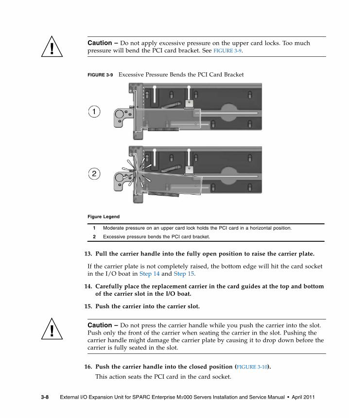
Caution – Do not apply excessive pressure on the upper card locks. Too muchpressure will bend the PCI card bracket. See FIGURE 3-9.
FIGURE 3-9 Excessive Pressure Bends the PCI Card Bracket
13. Pull the carrier handle into the fully open position to raise the carrier plate.
If the carrier plate is not completely raised, the bottom edge will hit the card socketin the I/O boat in Step 14 and Step 15.
14. Carefully place the replacement carrier in the card guides at the top and bottomof the carrier slot in the I/O boat.
15. Push the carrier into the carrier slot.
Caution – Do not press the carrier handle while you push the carrier into the slot.Push only the front of the carrier when seating the carrier in the slot. Pushing thecarrier handle might damage the carrier plate by causing it to drop down before thecarrier is fully seated in the slot.
16. Push the carrier handle into the closed position (FIGURE 3-10).
This action seats the PCI card in the card socket.
Figure Legend
1 Moderate pressure on an upper card lock holds the PCI card in a horizontal position.
2 Excessive pressure bends the PCI card bracket.
3-8 External I/O Expansion Unit for SPARC Enterprise Mx000 Servers Installation and Service Manual • April 2011

Caution – If the carrier handle does not close easily, the PCI card might not beseating properly in the card socket in the I/O boat. Remove the carrier and inspectthe PCI card. If the bottom of the PCI card is not perfectly horizontal, loosen the cardlocks and realign the card on the carrier. For troubleshooting information, seeAppendix D.
FIGURE 3-10 PCI Card and Carrier
17. Use the carrier locking screw located on the top of the handle to lock the carrierhandle in place.
18. Add the PCI card to an Oracle Solaris domain.
For details, refer to the service manual for your host server.
3.2 Replacing a PCI Card
Caution – If you install a PCI card while the External I/O Expansion Unit isrunning, be prepared to complete the installation in approximately two minutes. Ifyou leave a carrier slot empty, the External I/O Expansion Unit might overheat.
1. Use an antistatic strap for this procedure.
2. Remove the PCI card from the Oracle Solaris domain.
For details, refer to the service manual for your host server.
Figure Legend
1 Carrier handle (in closed position)
2 Carrier locking screw
Chapter 3 Working With PCI Cards 3-9

3. Remove the carrier from the carrier slot in the I/O boat.
a. Loosen the carrier locking screw on the carrier handle.
b. Press lightly on the front of the carrier, and pull the carrier handle out fully.
Caution – Pulling the carrier handle raises the carrier plate. If the carrier movesforward before the carrier plate is completely raised, the plastic locator bar(FIGURE 3-2) might be damaged by hitting the lower front edge of the I/O boat.
c. Pull the carrier out of the carrier slot and place on an antistatic surface.
4. Press the locking latch (FIGURE 3-11) while you push the carrier handle into theclosed position.
This action lowers the PCI card, facilitating the replacement of the card.
FIGURE 3-11 Closing the Carrier Handle
5. Remove the existing card from the carrier.
6. If you are installing an exact replacement, go to Step 8.
7. For very small PCI cards (1.25 in./31 mm tall or 3.0 in./76 mm wide), it isnecessary to do one or both of the following:
■ Move the long card lock (type B lock) from the horizontal slider slot to the frontvertical slider slot, then slide it down to reach the top of the PCI card.
■ Rotate the small card lock (type C lock) and slide it to the rear edge of the PCIcard.
See FIGURE 1-19 and FIGURE 1-20 for examples.
Figure Legend
1 Push carrier handle to the right
2 Push locking latch to the left
1
2
3-10 External I/O Expansion Unit for SPARC Enterprise Mx000 Servers Installation and Service Manual • April 2011

8. Place the PCI card on the carrier.
a. Place the front of the card inside the housing (FIGURE 3-12).
FIGURE 3-12 Inserting the PCI Card
Caution – Do not allow the bottom edge of the PCI card bracket to tear the RFIgasket in the front of the carrier (FIGURE 3-5).
b. A rectangular notch is located on the bottom front of the PCI card. Fit thenotch over the card alignment tab (item 1 in FIGURE 3-6), then fit the top of thecard bracket over the card alignment post (item 2 in FIGURE 3-6).
Figure Legend
1 See the following caution.
1
Chapter 3 Working With PCI Cards 3-11

FIGURE 3-13 Placing the PCI Card on the Carrier
9. Attach the PCI card to the carrier with one card lock:
a. Slide a card lock to the right edge of the PCI card.
b. Hold the card in place and partially tighten the card lock screw.
c. Verify that the PCI card is not tilted, then tighten the card lock screw.
Figure Legend
1 Card alignment tab
2 Card alignment post
1
2
3-12 External I/O Expansion Unit for SPARC Enterprise Mx000 Servers Installation and Service Manual • April 2011

FIGURE 3-14 Using Card Lock to Hold the PCI Card
10. Slide the remaining card locks to the edges of the PCI card and tighten thescrews.
The shape of a PCI card might prevent the use of some card locks. The minimumrequirement is one card lock on the side of the PCI card and one card lock on thetop.
Note – If the card lock screws are loose, the card locks will slip and the PCI card willnot seat properly.
Caution – If the bottom card lock (type C) is not used, leave it at the far right side ofthe slot (FIGURE 3-15). The PCI card will not seat properly if the bottom of the cardlock touches the card socket.
FIGURE 3-15 Location for an Unused Type C Card Lock
Figure Legend
1 Card lock
Figure Legend
1 Correct location and orientation for an unused type C card lock
1
1
Chapter 3 Working With PCI Cards 3-13

Caution – Do not apply excessive pressure on the upper card locks. Too muchvertical pressure will bend the PCI card bracket. See FIGURE 3-16.
FIGURE 3-16 Excessive Pressure Bends the PCI Card Bracket
11. Pull the carrier handle into the fully open position to raise the carrier plate.
Caution – If the carrier plate is not completely raised when you insert the carrier inStep 13, the plastic locator bar (FIGURE 3-17) might break by hitting the lower frontedge of the I/O boat.
Figure Legend
1 Moderate pressure on an upper card lock holds the PCI card in a horizontal position.
2 Excessive pressure on an upper card lock can bend the PCI card bracket.
3-14 External I/O Expansion Unit for SPARC Enterprise Mx000 Servers Installation and Service Manual • April 2011

FIGURE 3-17 Locator Bar on Carrier (Carrier Handle Shown in the Closed Position)
12. Carefully place the carrier in the card guides at the top and bottom of the carrierslot in the I/O boat.
13. Press on the metal front panel of the carrier to push the carrier fully into thecarrier slot.
Caution – Do not press the plastic carrier handle during Step 13. If you press thehandle, the PCI card and the sliding carrier plate might suddenly fall, breaking theplastic locator bar (FIGURE 3-17) by hitting it against the lower edge of the I/O boat.
14. Push the carrier handle into the closed position.
This action seats the PCI card in the card socket.
Caution – If the carrier handle does not close easily, the PCI card might not beseating properly in the card socket in the I/O boat. Remove the carrier and inspectthe PCI card. If the bottom of the PCI card is not perfectly horizontal, loosen the cardlocks and realign the card on the carrier. For troubleshooting information, seeAppendix D.
Chapter 3 Working With PCI Cards 3-15

FIGURE 3-18 PCI Card and Carrier
15. Use the carrier locking screw located on the top of the handle to lock the carrierhandle in place.
16. Add the PCI card to an Oracle Solaris domain.
For details, refer to the service manual for your host server.
3.3 Installing Cables for PCI Cards1. Use an antistatic strap for this procedure.
2. Route the cables across the top of the cable management unit as shown inFIGURE 3-19 or FIGURE 3-20.
a. Route the cables in the rack:
■ For the type A cable plate, route the cables along the both sides of the rack.
■ For the type B cable plate, route the cables along the right side of the rack.
b. Place the ends of the cables on the top of the cable plate, then curve thecables down to the corresponding PCI cards.
c. Use cable ties to hold the cables in place on the top of the cable managementunit.
Figure Legend
1 Carrier handle (in closed position)
2 Carrier locking screw
3-16 External I/O Expansion Unit for SPARC Enterprise Mx000 Servers Installation and Service Manual • April 2011

Note – Before tightening the cable ties, ensure that each cable has a service loop(freedom of movement) of at least 2 in./50 mm. This allows the cable plate andcables to be moved from the normal position (FIGURE 4-4) to the service positionwithout the need to untie the cables.
FIGURE 3-19 Example of Cable Management for the Type A Cable Plate
Chapter 3 Working With PCI Cards 3-17

FIGURE 3-20 Example of Cable Management for the Type B Cable Plate
3. Attach I/O cables from the PCI cards and their respective devices or networkports.
3-18 External I/O Expansion Unit for SPARC Enterprise Mx000 Servers Installation and Service Manual • April 2011

CHAPTER 4
Servicing and ReplacingComponents
This chapter includes the service procedures for replacing field-replaceable units andinstalling optional assemblies.
This chapter includes the following topics:
■ Section 4.1, “Service Procedures Task Map” on page 4-2
■ Section 4.2, “Identifying Firmware Versions” on page 4-3
■ Section 4.3, “Replacing a Power Supply Unit” on page 4-4
■ Section 4.4, “Powering Down a Link Before Service” on page 4-6
■ Section 4.5, “Preparing the Cable Plate for Service” on page 4-7
■ Section 4.6, “Replacing a Carrier” on page 4-9
■ Section 4.7, “Replacing a Link Cable” on page 4-13
■ Section 4.8, “Replacing a Link Card in the Host Server” on page 4-13
■ Section 4.9, “Replacing a Link Card in an I/O Boat” on page 4-14
■ Section 4.10, “Installing a Second I/O Boat” on page 4-16
■ Section 4.11, “Replacing an I/O Boat” on page 4-19
■ Section 4.12, “Replacing the External I/O Expansion Unit Chassis” on page 4-24
■ Section 4.13, “Powering Up a Link After Service” on page 4-33
4-1

4.1 Service Procedures Task Map
TABLE 4-1 Service Task Map
FRU Task Comments
PCI card • Install a new PCI card Section 3.1, “Installing a PCI Card” on page 3-1
• Replace an existing PCI card Section 3.2, “Replacing a PCI Card” on page 3-9
PSU • Replace a PSU Section 4.3, “Replacing a Power Supply Unit” on page 4-4
CableManagement
• Prepare the cable plate for I/O boatservice
Section 4.5, “Preparing the Cable Plate for Service” onpage 4-7
Carrier • Replace a carrier Section 4.6, “Replacing a Carrier” on page 4-9
Link • Replace a link cable Section 4.7, “Replacing a Link Cable” on page 4-13
• Replace a link card • Section 4.4, “Powering Down a Link Before Service” onpage 4-6
• Section 4.8, “Replacing a Link Card in the Host Server”on page 4-13
• Section 4.9, “Replacing a Link Card in an I/O Boat” onpage 4-14
• Section 4.13, “Powering Up a Link After Service” onpage 4-33
I/O boat • Install a second I/O boat Section 4.10, “Installing a Second I/O Boat” on page 4-16
• Replace an I/O boat • Section 4.11.1, “Replacing a Boat in a Single BoatConfiguration” on page 4-19
• Section 4.11.2, “Replacing a Boat in a Dual BoatConfiguration” on page 4-21
Chassis Replace the External I/O ExpansionUnit chassis
Section 4.12, “Replacing the External I/O Expansion UnitChassis” on page 4-24.
4-2 External I/O Expansion Unit for SPARC Enterprise Mx000 Servers Installation and Service Manual • April 2011

4.2 Identifying Firmware VersionsIt might be helpful to identify firmware versions in the External I/O Expansion Unitwhen troubleshooting problems. Firmware is located on the motherboard and oneach link card.
To identify versions of firmware, use the ioxadm -v list command. In the output,firmware versions are listed in the column marked “FW Ver”.
This example shows five instances of firmware in an External I/O Expansion Unitthat is configured with two I/O boats:
■ IOX in the Type column identifies the chassis, where the fan controller firmware islocated.
■ OP in the Type column identifies the link cards, where the bridge controllerfirmware is located. A link consists of two link cards, and there are two links inthis example (one link for each I/O boat), for a total of four link cards:
■ LINK in the Location column identifies a link card in an I/O boat.
■ IOU#n-PCI#n in the Location column identifies a link card in a server.
Refer to the ioxadm(8) man page for more information.
XSCF> ioxadm -v listLocation Type FW Ver Serial Num Part Num StateIOX@X04E IOX 2.4 XCX04E 5016937-03 OnIOX@X04E/PS0 A195 - T01180 3001701-03 OnIOX@X04E/PS1 A195 - T01097 3001701-03 OnIOX@X04E/IOB0 PCIX - XX00EL CF005016938/5016938-05 OnIOX@X04E/IOB0/LINK OP 2.4 XF01D3 CF005017040/5017040-03 OnIOU#0-PCI#3 OP 2.4 XF014C 5017040-03 OnIOX@X04E/IOB1 PCIE - XE00C1 CF005016939/5016939-04 OnIOX@X04E/IOB1/LINK OP 2.4 XF00W2 5017040-03 OnIOU#0-PCI#1 OP 2.4 XF01AX CF005017040/5017040-03 OnXSCF>
Chapter 4 Servicing and Replacing Components 4-3

4.3 Replacing a Power Supply UnitThis is a hot replacement procedure, meaning that the PSU can be replaced while thesystem is still running, provided that a second PSU is working properly.
1. Use an antistatic strap for this procedure.
2. Unpack the new power supply unit and set it flat on an antistatic surface.
Caution – Do not rest a PSU vertically. The plastic electrical connector on the back isbreakable.
3. If the system is running, power down the PSU with the ioxadm command:
Refer to the ioxadm (8) man page for more information.
4. At the front of the defective PSU, turn off the PSU AC switch and verify that theDC Power LED ( ) turns off.
5. Loosen the handle locking screw on the PSU handle.
6. Unlock the PSU by swinging the handle out 90 degrees into the fully openposition. (FIGURE 4-1).
7. Place a hand under the PSU to prevent it from falling, then pull the PSU out ofthe External I/O Expansion Unit.
Caution – The PSU is heavy (7.5 lb/3.4 kg).
When you can see the warning label on the top of the PSU, the PSU is almost fullyout of the PSU slot.
Caution – Do not allow the rear of the PSU to drop. The connector at the rear of thePSU can be damaged if it strikes the edge of the slot.
A pivoting flap behind the PSU drops down to prevent loss of cooling air.
XSCF> ioxadm poweroff target
4-4 External I/O Expansion Unit for SPARC Enterprise Mx000 Servers Installation and Service Manual • April 2011
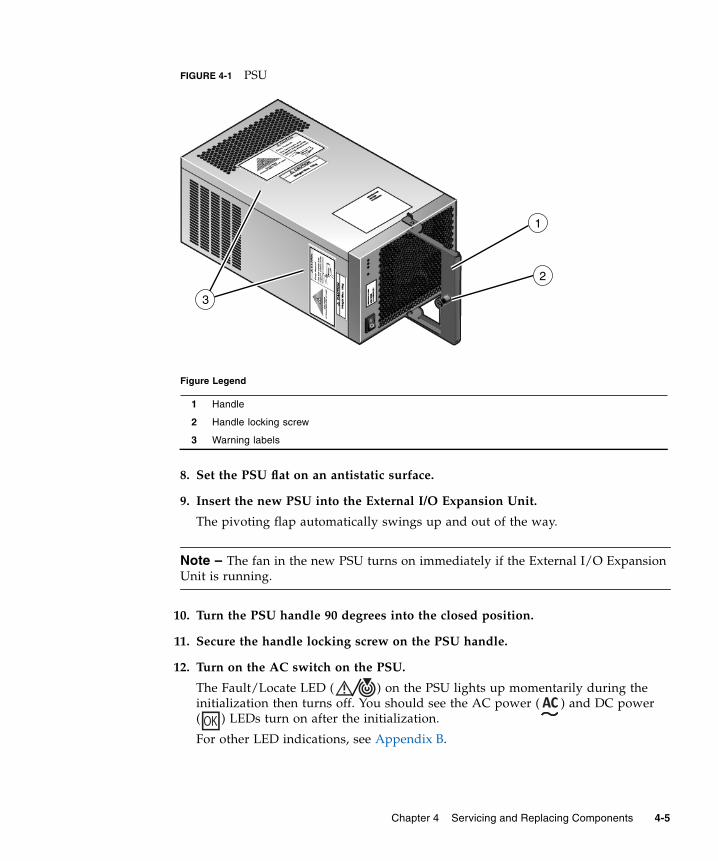
FIGURE 4-1 PSU
8. Set the PSU flat on an antistatic surface.
9. Insert the new PSU into the External I/O Expansion Unit.
The pivoting flap automatically swings up and out of the way.
Note – The fan in the new PSU turns on immediately if the External I/O ExpansionUnit is running.
10. Turn the PSU handle 90 degrees into the closed position.
11. Secure the handle locking screw on the PSU handle.
12. Turn on the AC switch on the PSU.
The Fault/Locate LED ( ) on the PSU lights up momentarily during theinitialization then turns off. You should see the AC power ( ) and DC power( ) LEDs turn on after the initialization.
For other LED indications, see Appendix B.
Figure Legend
1 Handle
2 Handle locking screw
3 Warning labels
2
1
3
Chapter 4 Servicing and Replacing Components 4-5

4.4 Powering Down a Link Before ServiceBefore you repair or replace any parts of a link, use this procedure to power downthe link. The link between a server and an I/O boat in the External I/O ExpansionUnit includes these parts:
■ The server IOU slot that contains a link card
■ The link card in the IOU slot
■ The link card in the I/O boat
■ The link cable or cables that connect the two link cards
■ The I/O boat
4.4.1 The cfgadm -c disconnect Command● Power down the link by disconnecting the server IOU slot:
Where ap_id is the server IOU slot that contains a link card.
For examples of ap_id IOU slot names in SPARC EnterpriseM4000/M5000/M8000/M9000 servers, see TABLE C-1 and TABLE C-2 in Appendix C.
4.4.2 Example of the cfgadm -c disconnectCommandThe following examples are for an External I/O Expansion Unit with one I/O boatconnected to a SPARC Enterprise M4000 server. In the examples, iou#0-pci#1 is theap_id for the server IOU slot to which the I/O boat is connected.
The following example shows the server IOU configuration while the I/O boat is stillconnected. The I/O boat serial number is displayed (iobE02EF), as are the six PCIslots in the I/O boat.
# cfgadm -c disconnect ap_id
# cfgadmiou#0-pci#0 scsi/hp connected configured okiou#0-pci#1 pci-pci/hp connected configured okiou#0-pci#1:iobE02EF.pcie1 fibre/hp connected configured okiou#0-pci#1:iobE02EF.pcie2 etherne/hp connected configured okiou#0-pci#1:iobE02EF.pcie3 fibre/hp connected configured ok
4-6 External I/O Expansion Unit for SPARC Enterprise Mx000 Servers Installation and Service Manual • April 2011

The next example shows the command that powers down (disconnects) the link,followed by a command that displays the results.
Note that iou#0-pci#1 is disconnected, and the six slots in the I/O boat havedisappeared.
4.5 Preparing the Cable Plate for ServiceOn the cable management unit, raise the cable plate (FIGURE 4-2 or FIGURE 4-3) toprovide easier removal of a PCI carrier or I/O boat.
1. Use an antistatic strap for this procedure.
2. Loosen two cable plate locking screws (item 3 in FIGURE 4-4).
3. Pull the cable plate toward you approximately 0.5 in./13 mm, then raise itapproximately 0.75 in./20 mm, until the bottom of the plate is above the tops ofthe support brackets.
4. Push the cable plate forward to its service position (FIGURE 4-4) so that the cableplate rests on the support brackets.
The tabs on the sides of the cable plate should lie in the small notches on the topsof the support brackets.
iou#0-pci#1:iobE02EF.pcie4 unknown empty unconfigured unknowniou#0-pci#1:iobE02EF.pcie5 fibre/hp connected configured okiou#0-pci#1:iobE02EF.pcie6 unknown empty unconfigured unknowniou#0-pci#2 unknown empty unconfigured unknowniou#0-pci#3 etherne/hp connected configured okiou#0-pci#4 pci-pci/hp connected configured ok
# cfgadm -c disconnect iou#0-pci#1# cfgadmiou#0-pci#0 scsi/hp connected configured okiou#0-pci#1 unknown disconnected unconfigured unknowniou#0-pci#2 unknown empty unconfigured unknowniou#0-pci#3 etherne/hp connected configured okiou#0-pci#4 pci-pci/hp connected configured ok
Chapter 4 Servicing and Replacing Components 4-7

FIGURE 4-2 Type A Cable Plate
FIGURE 4-3 Type B Cable Plate
The left side of FIGURE 4-4 shows the cable plate in its normal position.
The right side of the illustration shows the service position.
4-8 External I/O Expansion Unit for SPARC Enterprise Mx000 Servers Installation and Service Manual • April 2011

FIGURE 4-4 Cable Plate (Side Views of Normal and Service Positions)
5. After the carrier or I/O boat has been replaced, move the cable plate down intoits normal position and tighten the cable plate locking screws.
4.6 Replacing a Carrier1. If necessary, power down the link.
■ If the carrier is in slot 0 (LINK 0), first power down the link. See Section 4.4,“Powering Down a Link Before Service” on page 4-6.
■ If the carrier is in slots 1 through 6 (PCIE 1-6 or PCIX 1-6), it is not necessary topower off the External I/O Expansion Unit.
2. Use an antistatic strap for this procedure.
3. Move the cable plate to the service position:
a. Loosen the cable plate locking screw(s) (item 3 in FIGURE 4-4).
b. Pull the cable plate toward you approximately 0.5 in./13 mm, then raise itapproximately 0.75 in./20 mm, until the bottom of the plate is above the topsof the support brackets.
c. Push the cable plate forward to its service position (FIGURE 4-4) so that thecable plate rests on the support brackets.
The tabs on the sides of the cable plate should lie in the small notches on thetops of the support brackets.
Figure Legend
1 Cable plate in the normal position (lowered)
2 Cable plate in the service position (raised)
3 Cable plate locking screw (two places)
12
3
Chapter 4 Servicing and Replacing Components 4-9

4. Disconnect the I/O cable(s) from the PCI card in the carrier.
5. Remove the carrier from the I/O boat:
a. Loosen the carrier locking screw on the carrier handle.
b. Pull the carrier handle out fully.
Caution – Pulling the carrier handle raises the carrier plate. If the carrier movesforward before the carrier plate is completely raised, the plastic locator bar(FIGURE 3-2) might be damaged by hitting the lower front edge of the I/O boat.
c. Pull the carrier out of the carrier slot and place it on an antistatic surface.
d. Press the locking latch (FIGURE 3-3) while you push the carrier handle into theclosed position.
This action lowers the carrier plate, giving you more room to move the PCIcard into place on the carrier.
6. Install an M2 screw on the replacement carrier, in the key hole (FIGURE 4-5) thatcorresponds to the slot number of the defective carrier.
Carriers are keyed to specific slots in an I/O boat. If a carrier does not fit in a slot,verify that the M2 screw is in the hole that corresponds to that slot.
4-10 External I/O Expansion Unit for SPARC Enterprise Mx000 Servers Installation and Service Manual • April 2011

FIGURE 4-5 Screw Hole Locations for the Carrier Slot Key
7. Attach a label with the slot name and number to the carrier.
The replacement carrier includes an assortment of adhesive labels including LINK0, PCIX 1, PCIE 1, and so forth. Use the replacement label that corresponds to thelabel on the defective carrier. Place the label just below the opening in the front ofthe carrier (FIGURE 4-5).
8. Transfer the PCI card from the defective carrier to the replacement carrier:
a. Remove the dummy card from the replacement carrier by loosening thePhillips screws on the card locks.
b. Examine the defective carrier and determine which card locks on thereplacement carrier will be used. Move the card locks on the replacementcarrier to approximately the same locations as on the defective carrier.
One or more card locks on the replacement carrier might not be needed. Movethe unused card locks out of the way or else remove them entirely from thecarrier.
Figure Legend
1 Key
2 Keyholes 0-7*
* Keyhole 7 is reserved for future use.
3 Carrier label
3
2
1
Chapter 4 Servicing and Replacing Components 4-11

c. Unlock the PCI card from the defective carrier and install the card on thereplacement carrier.
d. If the type C lock is used, ensure that it is not located where it will hit thecard socket in the I/O boat.
9. Install the carrier in the I/O boat:
a. Pull the carrier handle into the fully open position to raise the carrier plate.
b. Carefully place the carrier in the card guides at the top and bottom of thecarrier slot in the I/O boat.
c. Press on the metal front panel of the carrier to push the carrier fully into thecarrier slot.
Caution – Do not press the plastic carrier handle during Step c. If you press thehandle, the PCI card and the sliding carrier plate might suddenly fall, breaking theplastic locator bar (FIGURE 3-17) by hitting it against the lower edge of the I/O boat.
d. Push the carrier handle into the closed position.
This action seats the PCI card in the card socket.
Caution – If the carrier handle does not close easily, the PCI card might not beseating properly in the card socket in the I/O boat. Remove the carrier and inspectthe PCI card. If the bottom of the PCI card is not perfectly horizontal, loosen the cardlocks and realign the card on the carrier. For troubleshooting information, seeAppendix D.
e. Lock the carrier handle into place with the carrier locking screw located onthe top of the handle.
f. Connect the I/O cable(s) to the PCI card.
10. Move the cable plate back into the normal position (FIGURE 4-4) and tighten thecable plate locking screw(s).
11. If this is a link card, power up the link.
See Section 4.13, “Powering Up a Link After Service” on page 4-33.
4-12 External I/O Expansion Unit for SPARC Enterprise Mx000 Servers Installation and Service Manual • April 2011

4.7 Replacing a Link CableThis is not a hot replacement procedure. Link operations will be interrupted.
Note – Ordering a complete set of replacements at one time can shorten thetroubleshooting process. If you cannot determine if a link problem is caused by a linkcard or a link cable, order replacement link cards for the host and the I/O boat, alongwith a copper link cable or two optical link cables, as appropriate.
1. Power down the link.
See Section 4.4, “Powering Down a Link Before Service” on page 4-6.
2. Use an antistatic strap for this procedure.
3. Replace the link cable or cables.
If you are replacing a copper link cable, there is one cable. Both ends of the cableare identical.
If you are replacing one or both cables in an optical link, note that the ends of eachcable have either a TX label (Transmit) or an RX (Receive) label. It is possible toplug a connector into the wrong socket on a link card, so ensure that you plugeach connector into the appropriately marked TX or RX socket on the link cards.
4. Power up the link.
See Section 4.13, “Powering Up a Link After Service” on page 4-33.
4.8 Replacing a Link Card in the Host ServerThis is not a hot replacement procedure. Link operations will be interrupted.
Note – Ordering a complete set of replacements at one time can shorten thetroubleshooting process. If you cannot determine if a link problem is caused by a linkcard or a link cable, order replacement link cards for the host and the I/O boat, alongwith a copper link cable or two optical link cables, as appropriate.
1. Power down the link.
See Section 4.4, “Powering Down a Link Before Service” on page 4-6.
2. Use an antistatic strap for this procedure.
Chapter 4 Servicing and Replacing Components 4-13

3. Disconnect the link cable or cables from the link card in the host server.
A copper link has one cable. An optical link has two cables.
4. Replace the link card in the host server.
Refer to the service manual for your host server for instructions on replacing PCIcards.
5. Connect the link cable to the replacement link card.
6. Power up the link.
See Section 4.13, “Powering Up a Link After Service” on page 4-33.
4.9 Replacing a Link Card in an I/O BoatThis is not a hot replacement procedure. Link operations will be interrupted.
Note – Ordering a complete set of replacements at one time can shorten thetroubleshooting process. If you cannot determine if a link problem is caused by a linkcard or a link cable, order replacement link cards for the host and the I/O boat, alongwith a copper link cable or two optical link cables, as appropriate.
1. Power down the link.
See Section 4.4, “Powering Down a Link Before Service” on page 4-6.
2. Use an antistatic strap for this procedure.
3. Move the cable plate to the service position:
a. Loosen the cable plate locking screw(s) (item 3 in FIGURE 4-4).
b. Pull the cable plate toward you approximately 0.5 in./13 mm, then raise itapproximately 0.75 in./20 mm, until the bottom of the plate is above the topsof the support brackets.
c. Push the cable plate forward to its service position (FIGURE 4-4) so that thecable plate rests on the support brackets.
The tabs on the sides of the cable plate should lie in the small notches on thetops of the support brackets.
4. Disconnect the link cable from the defective link card in the I/O boat.
5. Remove the defective link card and carrier from slot 0 in the I/O boat.
a. Loosen the carrier locking screw on the carrier handle.
4-14 External I/O Expansion Unit for SPARC Enterprise Mx000 Servers Installation and Service Manual • April 2011

b. Pull the carrier handle out fully.
Caution – Pulling the carrier handle raises the carrier plate. If the carrier movesforward before the carrier plate is completely raised, the plastic locator bar(FIGURE 3-2) might be damaged by hitting the lower front edge of the I/O boat.
c. Pull the carrier out of the carrier slot and place it on an antistatic surface.
d. Press the locking latch (FIGURE 3-3) while you push the carrier handle into theclosed position.
This action lowers the carrier plate, giving you more room to move the PCIcard into place on the carrier.
6. Remove the defective link card from the carrier.
7. Install the replacement link card in the carrier.
8. Install the carrier in slot 0 of the I/O boat:
a. Pull the carrier handle into the fully open position to raise the carrier plate.
b. Carefully place the carrier in the card guides at the top and bottom of thecarrier slot in the I/O boat.
c. Press on the metal front panel of the carrier to push the carrier fully into thecarrier slot.
Caution – Do not press the plastic carrier handle during Step c. If you press thehandle, the PCI card and the sliding carrier plate might suddenly fall, breaking theplastic locator bar (FIGURE 3-17) by hitting it against the lower edge of the I/O boat.
d. Push the carrier handle into the closed position.
This action seats the PCI card in the card socket.
Caution – If the carrier handle does not close easily, the PCI card might not beseating properly in the card socket in the I/O boat. Remove the carrier and inspectthe PCI card. If the bottom of the PCI card is not perfectly horizontal, loosen the cardlocks and realign the card on the carrier. For troubleshooting information, seeAppendix D.
e. Lock the carrier handle into place with the carrier locking screw located onthe top of the handle.
9. Attach the link cable to the link card.
Chapter 4 Servicing and Replacing Components 4-15

Note – If the External I/O Expansion Unit has two I/O boats, both boats must beconnected to the same host server. Do not connect the second boat to a differentserver. Also, do not connect the second boat to the first boat; a daisy-chainconfiguration is not allowed.
10. Move the cable plate back into the normal position (FIGURE 4-4) and tighten thecable plate locking screw(s).
11. Power up the link.
See Section 4.13, “Powering Up a Link After Service” on page 4-33.
4.10 Installing a Second I/O BoatThe following procedures apply to both types of I/O boat (PCI-X or PCI Express).
1. Use an antistatic strap for this procedure.
2. Unpack the new I/O boat and set it flat on an antistatic surface.
Caution – Do not rest an I/O boat vertically. The plastic electrical connector on theback is breakable.
3. If a link card and carrier are already installed in the new I/O boat, go to Step 6.
4. If a link card and carrier are not already installed in the new I/O boat:
Slot 0 is used for the link card. The carrier is labelled Link 0.
a. Loosen the carrier locking screw on the carrier handle.
b. Pull the carrier handle out fully.
Caution – Pulling the carrier handle raises the carrier plate. If the carrier movesforward before the carrier plate is completely raised, the plastic locator bar(FIGURE 3-2) might be damaged by hitting the lower front edge of the I/O boat.
c. Pull the carrier out of the carrier slot and place it on an antistatic surface.
4-16 External I/O Expansion Unit for SPARC Enterprise Mx000 Servers Installation and Service Manual • April 2011

d. Press the locking latch (FIGURE 3-1) while you push the carrier handle into theclosed position.
This action lowers the carrier plate, giving you more room to move the PCIcard into place on the carrier.
e. Remove the dummy card from the carrier.
One side of the dummy card provides instructions for removal from the carrier.The other side of the dummy card provides instructions for installing a PCIcard.
f. Install the link card on the carrier.
For help in choosing the correct card locks to install a PCI card, seeSection 1.3.2, “Card Locks” on page 1-20.
5. Install the carrier in the I/O boat:
a. Pull the carrier handle into the fully open position to raise the carrier plate.
b. Carefully place the carrier in the card guides at the top and bottom of thecarrier slot in the I/O boat.
c. Press on the metal front panel of the carrier to push the carrier fully into thecarrier slot.
Caution – Do not press the plastic carrier handle during Step c. If you press thehandle, the PCI card and the sliding carrier plate might suddenly fall, breaking theplastic locator bar (FIGURE 3-17) by hitting it against the lower edge of the I/O boat.
d. Push the carrier handle into the closed position.
This action seats the PCI card in the card socket.
Caution – If the carrier handle does not close easily, the PCI card might not beseating properly in the card socket in the I/O boat. Remove the carrier and inspectthe PCI card. If the bottom of the PCI card is not perfectly horizontal, loosen the cardlocks and realign the card on the carrier. For troubleshooting information, seeAppendix D.
e. Lock the carrier handle into place with the carrier locking screw located onthe top of the handle.
6. Install PCI cards in the I/O boat.
See Step 4 and Step 5 above for instructions to safely remove and insert carriers.
7. In the rack, move the cable plate to the service position:
Chapter 4 Servicing and Replacing Components 4-17

a. Loosen the cable plate locking screw(s) (item 3 in FIGURE 4-4).
b. Pull the cable plate toward you approximately 0.5 in./13 mm, then raise itapproximately 0.75 in./20 mm, until the bottom of the plate is above the topsof the support brackets.
c. Push the cable plate forward to its service position (FIGURE 4-4) so that thecable plate rests on the support brackets.
The tabs on the sides of the cable plate should lie in the small notches on thetops of the support brackets.
8. Remove the filler panel from the unused I/O boat slot by loosening the twocaptive screws at the top of the filler panel.
A pivoting flap behind the filler panel drops down to prevent loss of cooling air.
9. Insert the I/O boat into the I/O boat slot.
The pivoting flap automatically swings up and out of the way.
10. Lock the I/O boat in place with the two captive screws at the top of the boat.
11. Move the cable plate back into the normal position (FIGURE 4-4) and tighten thecable plate locking screws.
12. Install the remaining link card in the host server.
Refer to documentation for your host server for instructions.
13. Connect the link cable or cables between the link card in the server and the linkcard in the I/O boat.
14. Attach the I/O cables to the PCI cards.
15. Attach the I/O cables to the cable management unit on the External I/OExpansion Unit.
Allow approximately 2 in./50 mm of cable movement. This permits movement ofthe cable plate from its normal location to its service position.
16. Power up the link.
See Section 4.13, “Powering Up a Link After Service” on page 4-33.
4-18 External I/O Expansion Unit for SPARC Enterprise Mx000 Servers Installation and Service Manual • April 2011

4.11 Replacing an I/O Boat
4.11.1 Replacing a Boat in a Single Boat ConfigurationThis is a cold service procedure.
1. If the link is still running, power down the link.
See Section 4.4, “Powering Down a Link Before Service” on page 4-6.
2. Use an antistatic strap for this procedure.
3. At the front of the External I/O Expansion Unit, turn off the AC switches locatedon the PSUs.
4. Move the cable plate to the service position:
a. Loosen the cable plate locking screw(s) (item 3 in FIGURE 4-4).
b. Pull the cable plate toward you approximately 0.5 in./13 mm, then raise itapproximately 0.75 in./20 mm, until the bottom of the plate is above the topsof the support brackets.
c. Push the cable plate forward to its service position (FIGURE 4-4) so that thecable plate rests on the support brackets.
The tabs on the sides of the cable plate should lie in the small notches on thetops of the support brackets.
5. Label all I/O cables.
6. Disconnect the link cable from the link card in slot 0 in the I/O boat.
7. Disconnect the I/O cables from the PCI cards in the I/O boat.
8. Remove the I/O boat from the I/O boat slot and set it flat on an antistaticsurface.
When you can see the warning label on the top of the I/O boat, the boat is almostfully out of the boat slot.
Chapter 4 Servicing and Replacing Components 4-19

Caution – Do not allow the rear of the I/O boat to drop. The connector at the rear ofthe boat can be damaged if it strikes the edge of the slot.
Do not rest an I/O boat vertically. The plastic electrical connector on the back isbreakable.
A pivoting flap behind the I/O boat drops down to prevent loss of cooling air.
9. Insert the replacement I/O boat into the I/O boat slot.
The pivoting flap automatically swings up and out of the way.
10. Lock the I/O boat in place with the two captive screws at the top of the boat.
11. Remove the link carrier from slot 0 in the old I/O boat.
The link carrier is labelled Link 0.
a. Loosen the carrier locking screw on the carrier handle.
b. Pull the carrier handle out fully.
Caution – Pulling the carrier handle raises the carrier plate. If the carrier movesforward before the carrier plate is completely raised, the plastic locator bar(FIGURE 3-2) might be damaged by hitting the lower front edge of the I/O boat.
c. Pull the carrier out of the carrier slot.
12. Install the link carrier in the slot marked Link 0 in the new I/O boat:
a. Pull the carrier handle into the fully open position to raise the carrier plate.
b. Carefully place the carrier in the card guides at the top and bottom of thecarrier slot in the I/O boat.
c. Press on the metal front panel of the carrier to push the carrier fully into thecarrier slot.
Caution – Do not press the plastic carrier handle during Step c. If you press thehandle, the PCI card and the sliding carrier plate might suddenly fall, breaking theplastic locator bar (FIGURE 3-17) by hitting it against the lower edge of the I/O boat.
d. Push the carrier handle into the closed position.
This action seats the PCI card in the card socket.
4-20 External I/O Expansion Unit for SPARC Enterprise Mx000 Servers Installation and Service Manual • April 2011

Caution – If the carrier handle does not close easily, the PCI card might not beseating properly in the card socket in the I/O boat. Remove the carrier and inspectthe PCI card. If the bottom of the PCI card is not perfectly horizontal, loosen the cardlocks and realign the card on the carrier. For troubleshooting information, seeAppendix D.
e. Lock the carrier handle into place with the carrier locking screw located onthe top of the handle.
13. Move PCI cards and carriers from slots 1 through 6 in the old I/O boat to thenew I/O boat.
See Step 11 and Step 12 above for instructions to safely remove and insert carriers.
14. Attach the I/O cables to the PCI cards.
15. Move the cable plate back into the normal position (FIGURE 4-4) and tighten thecable plate locking screw(s).
16. Connect the link cable or cables between the link card in the host server and thelink card in the I/O boat.
17. Turn on the AC switches on the External I/O Expansion Unit PSUs.
On the PSUs the AC power ( ) and DC power ( ) LEDs should light.
For other LED indications, see Appendix B.
18. Power up the link.
See Section 4.13, “Powering Up a Link After Service” on page 4-33.
4.11.2 Replacing a Boat in a Dual Boat Configuration1. If the I/O boat is still operating, power down the link.
See Section 4.4, “Powering Down a Link Before Service” on page 4-6.
2. Use an antistatic strap for this procedure.
3. Move the cable plate to the service position:
a. Loosen the cable plate locking screw(s) (item 3 in FIGURE 4-4).
b. Pull the cable plate toward you approximately 0.5 in./13 mm, then raise itapproximately 0.75 in./20 mm, until the bottom of the plate is above the topsof the support brackets.
Chapter 4 Servicing and Replacing Components 4-21

c. Push the cable plate forward to its service position (FIGURE 4-4) so that thecable plate rests on the support brackets.
The tabs on the sides of the cable plate should lie in the small notches on thetops of the support brackets.
4. Label all I/O cables.
5. Replace the defective I/O boat:
a. Disconnect the link cable from the link card in slot 0 in the I/O boat.
b. Disconnect the I/O cables from the PCI cards in the I/O boat.
c. Loosen the captive screws (item 2 in FIGURE 1-4) at the top of the I/O boat.
d. Remove the I/O boat and set it flat on an antistatic surface.
When you can see the warning label on the top of the I/O boat, the boat isalmost fully out of the boat slot.
Caution – Do not allow the rear of the I/O boat to drop. The connector at the rear ofthe boat can be damaged if it strikes the edge of the slot.
Do not rest an I/O boat vertically. The plastic electrical connector on the back isbreakable.
A pivoting flap behind the I/O boat drops down to prevent loss of cooling air.
e. Insert the replacement I/O boat into the I/O boat slot.
The pivoting flap automatically swings up and out of the way.
f. Tighten the captive screws at the top of the I/O boat.
6. Install a link card and carrier in the I/O boat, if not already installed.
Slot 0 is used for the link card. It is the farthest left slot in the boat.
a. Remove the carrier from the I/O boat.
Each carrier is keyed to fit in a specific slot. (The key is an M2 screw located atthe top front of the carrier.) A label on the front of the carrier shows the slotnumber.
Caution – The carrier can be damaged during removal and during insertion. Forsafe handling of the carrier, read the cautions in Section 3.1, “Installing a PCI Card”on page 3-1.
4-22 External I/O Expansion Unit for SPARC Enterprise Mx000 Servers Installation and Service Manual • April 2011

b. Remove the dummy card from a carrier.
One side of the dummy card provides instructions for removal from the carrier.The other side of the dummy card provides instructions for installing a PCIcard.
c. Install a link card on the carrier.
For help in choosing the correct card locks to install a PCI card, seeSection 1.3.2, “Card Locks” on page 1-20.
7. Install the carrier in the I/O boat:
a. Pull the carrier handle into the fully open position to raise the carrier plate.
b. Carefully place the carrier in the card guides at the top and bottom of thecarrier slot in the I/O boat.
c. Press on the metal front panel of the carrier to push the carrier fully into thecarrier slot.
Caution – Do not press the plastic carrier handle during Step c. If you press thehandle, the PCI card and the sliding carrier plate might suddenly fall, breaking theplastic locator bar (FIGURE 3-17) by hitting it against the lower edge of the I/O boat.
d. Push the carrier handle into the closed position.
This action seats the PCI card in the card socket.
Caution – If the carrier handle does not close easily, the PCI card might not beseating properly in the card socket in the I/O boat. Remove the carrier and inspectthe PCI card. If the bottom of the PCI card is not perfectly horizontal, loosen the cardlocks and realign the card on the carrier. For troubleshooting information, seeAppendix D.
e. Lock the carrier handle into place with the carrier locking screw located onthe top of the handle.
8. Move PCI cards and carriers from slots 1 through 6 in the old I/O boat to thenew I/O boat.
See Step 6 and Step 7 above for instructions to safely remove and insert carriers.
9. Attach the I/O cables to the PCI cards.
10. Move the cable plate back into the normal position (Step 4-4) and tighten thecable plate locking screw(s).
11. Connect the link cable between the link card in the host server and the link cardin the I/O boat.
Chapter 4 Servicing and Replacing Components 4-23

12. Power up the link.
See Section 4.13, “Powering Up a Link After Service” on page 4-33.
4.12 Replacing the External I/O ExpansionUnit ChassisIn this procedure, the following parts are moved from the old chassis to thereplacement chassis:
■ Front bezel
■ I/O boat(s)
■ PSUs
4.12.1 Locating the New System Serial Number LabelThe replacement chassis has a new system serial number. This serial number label islocated inside the left I/O boat bay.
In the following procedure, new serial number labels will be attached to the oldbezel, and the old bezel will be used with the new chassis.
New system serial number labels are not provided for the top cover. The old topcover will not be used on the new chassis.
4.12.2 Preparing the External I/O Expansion Unit1. Use an antistatic strap for this procedure.
2. Unpack the replacement chassis and place it on an antistatic work space.
Note – Use an antistatic work space that is wide enough to accommodate twoExternal I/O Expansion Units side by side (40 in./1000 mm).
3. Power down the link.
See Section 4.4, “Powering Down a Link Before Service” on page 4-6.
4. Turn off the AC switches on both PSUs at the front of the External I/OExpansion Unit.
4-24 External I/O Expansion Unit for SPARC Enterprise Mx000 Servers Installation and Service Manual • April 2011

5. At the rear of the External I/O Expansion Unit, disconnect the AC cords from theinternal AC cables.
6. Move the cable plate to the service position:
a. Loosen the cable plate locking screw(s) (item 3 in FIGURE 4-4).
b. Pull the cable plate toward you approximately 0.5 in./13 mm, then raise itapproximately 0.75 in./20 mm, until the bottom of the plate is above the topsof the support brackets.
c. Push the cable plate forward to its service position (FIGURE 4-4) so that thecable plate rests on the support brackets.
The tabs on the sides of the cable plate should lie in the small notches on thetops of the support brackets.
7. Label all I/O cables.
8. Disconnect the link cable from the link card in slot 0 in each I/O boat
9. Disconnect all I/O cables from the PCI cards in the External I/O Expansion Unit.
10. Remove the I/O boat(s) from the original External I/O Expansion Unit:
a. Loosen the two captive screws located at the top of the I/O boat.
b. Pull the I/O boat out of the chassis approximately 6 in./150 mm.
c. Support the bottom of the I/O boat with one hand, then pull the boat out ofthe slot.
d. Set the I/O boat flat on an antistatic surface.
Caution – Do not rest an I/O boat vertically. The plastic electrical connector on theback is breakable.
e. Note which boat is boat 0 and which is boat 1 so that they will go in the sameslots in the replacement chassis.
Label the boats.
11. Remove the PSUs from the front of the External I/O Expansion Unit:
a. Loosen the handle locking screw on the PSU handle.
b. Unlock the PSU by pulling it out 90 degrees.
c. Pull the PSU out approximately 6 in./150 mm and stop.
Chapter 4 Servicing and Replacing Components 4-25

Caution – The PSU is heavy (7.5 lb/3.4 kg).
When you can see the warning label on the top of the PSU, the PSU is almostfully out of the PSU slot.
Caution – Do not allow the rear of the PSU to drop. The connector at the rear of thePSU can be damaged if it strikes the edge of the slot.
d. Support the bottom of the PSU with one hand, and pull the PSU out of theExternal I/O Expansion Unit.
e. Set the PSU flat on an antistatic surface.
Caution – Do not rest a PSU vertically. The plastic electrical connector on the back isbreakable.
12. Remove the External I/O Expansion Unit chassis from the rack.
a. Use a No. 2 Phillips screwdriver to remove the four mounting screws fromthe front of the chassis (FIGURE 2-6).
b. Pull the chassis out of the rack and place it on an antistatic workbench.
The empty chassis weighs 30 lb (13.6 kg).
4.12.3 Moving the Bezel to the New Chassis1. Use an antistatic strap for this procedure.
2. Remove the bezel from the old chassis:
a. Use a No. 1 Phillips screwdriver to remove the top cover (FIGURE 4-6).
There are 14 screws on the cover:
■ 2 screws on the right side
■ 2 screws on the left side
■ 10 screws on the top
Note that the top cover of the old chassis can be identified by the presence ofservice labels. The top cover of the new chassis does not have service labels.
4-26 External I/O Expansion Unit for SPARC Enterprise Mx000 Servers Installation and Service Manual • April 2011

FIGURE 4-6 Removing the Chassis Top Cover
b. Set the cover aside.
c. Use a No. 1 Phillips screwdriver to remove 4 screws from the top of the bezel(FIGURE 4-7), then tilt the top of the bezel away from the External I/OExpansion Unit and lift it off.
Figure Legend
1 Top screw locations (10 total)
2 Side screw locations (4 total)
2
1
Chapter 4 Servicing and Replacing Components 4-27

FIGURE 4-7 Bezel Screws
3. Install new serial number labels on the bezel.
The current serial number labels are located at the left PSU opening of the bezel(FIGURE 4-8).
Figure Legend
1 Bezel screws
1
4-28 External I/O Expansion Unit for SPARC Enterprise Mx000 Servers Installation and Service Manual • April 2011

FIGURE 4-8 Serial Number Labels
4. Use a No. 1 Phillips screwdriver to remove the top cover (FIGURE 4-6) from thenew chassis.
5. Set the cover aside.
This cover will be used with the new chassis.
Note – Do not attempt to move the service labels from the old cover to the newcover. The new cover will be used without service labels.
6. Install the bezel on the replacement External I/O Expansion Unit chassis:
a. Tilt the bezel away from the External I/O Expansion Unit approximately 10degrees.
b. Place the bottom edge of the bezel under the front of the chassis.
The lugs on the bottom of the chassis front fit into the slots in the bezel.
c. Tilt the bezel upright and use 4 No. 1 Phillips screws to attach the top of thebezel to the replacement chassis.
Figure Legend
1 Upper serial number label
2 Lower serial number label
1
2
Chapter 4 Servicing and Replacing Components 4-29

7. Install the new top cover on the replacement External I/O Expansion Unitchassis.
Note – The new top cover does not have system serial number label. The newsystem serial number is located only on labels on the bezel (FIGURE 4-8) and inside theleft I/O boat bay of the FRU chassis.
Install 10 No. 1 Phillips screws on the top. Install 2 No. 1 Phillips screws on eachside.
8. Install the old top cover on the old chassis.
4.12.4 Installing the External I/O Expansion Unit in theRack1. Use an antistatic strap for this procedure.
2. Use a No. 2 Phillips screwdriver to remove the left and right chassis lockbrackets from the sides of the old chassis (FIGURE 4-9).
4-30 External I/O Expansion Unit for SPARC Enterprise Mx000 Servers Installation and Service Manual • April 2011

FIGURE 4-9 Uninstalling the Chassis Lock Brackets
3. Set the old chassis aside for return or proper disposal.
4. Install the chassis lock brackets on the sides of the replacement chassis.
5. Slide the replacement chassis into the rack and lock the chassis in place, usingtwo No. 2 Phillips screws for each of the chassis lock brackets (FIGURE 4-10).
Chapter 4 Servicing and Replacing Components 4-31

FIGURE 4-10 Installing the External I/O Expansion Unit in the Rack
6. At the front of the chassis, install the PSUs:
a. Pull the PSU handle to the unlocked position.
b. Slide the PSU into the slot until the rear of the PSU contacts the centerplane.
c. Turn the PSU handle into the locked position.
d. Tighten the handle locking screw on the handle.
e. Verify that the AC switches are in the Off position.
7. At the rear of the chassis, install the I/O boats.
a. Carefully slide I/O boat 0 into slot 0.
Lift the I/O cables out of the way as necessary.
b. Lock the I/O boat in place by tightening the two screws at the top corners ofthe I/O boat.
4-32 External I/O Expansion Unit for SPARC Enterprise Mx000 Servers Installation and Service Manual • April 2011
c. Install I/O boat 1 in the same manner.
8. Lower the cable plate from the service position to the normal position(FIGURE 4-4).
9. Attach the I/O cables to the PCI cards.
10. For each I/O boat, attach the link cable(s) to the link card in the boat.
For an optical link card, there are two connections. Insert the TX cable into the linkcard port marked “TX” and insert the RX cable into the port marked “RX”.
For a copper link card, there is a single connection.
11. Connect AC cords to the internal AC cables on the External I/O Expansion Unit.
12. Turn on the AC switches on the External I/O Expansion Unit PSUs.
On the PSUs the AC power ( ) and DC power ( ) LEDs should light.
For other LED indications, see Appendix B.
13. Add the PCI card to an Oracle Solaris domain.
For details, refer to the service manual for your host server.
4.13 Powering Up a Link After Service
4.13.1 The cfgadm -c configure Command● After repairing a link, power up the link by typing:
Where ap_id is the IOU slot in the host server to which the I/O boat is connected.For examples of IOU slot names in SPARC EnterpriseM4000/M5000/M8000/M9000 servers, see TABLE C-1 and TABLE C-2 in Appendix C.
# cfgadm -c configure ap_id
# cfgadm -c configure ap_id
Chapter 4 Servicing and Replacing Components 4-33

4.13.2 Example of the cfgadm -c configure CommandThe following examples are for an External I/O Expansion Unit with one I/O boatconnected to a SPARC Enterprise M4000 server. In the examples, the ap_id for theserver IOU slot to which the I/O boat is connected is iou#0-pci#1.
The following command shows the server I/O configuration before the link ispowered up.
Note that in the configuration this IOU slot is shown as disconnected, which meansthat the link is powered down.
The two commands in the following example power up the link and display the newconfiguration.
Note that the output now shows that IOU slot iou#0-pci#1 is connected andconfigured. The output also lists the I/O boat serial number (iobE02EF) and the sixPCI slots in the I/O boat.
# cfgadmiou#0-pci#0 scsi/hp connected configured okiou#0-pci#1 unknown disconnected unconfigured unknowniou#0-pci#2 unknown empty unconfigured unknowniou#0-pci#3 etherne/hp connected configured okiou#0-pci#4 pci-pci/hp connected configured ok
# cfgadm -c configure iou#0-pci#1# cfgadmiou#0-pci#0 scsi/hp connected configured okiou#0-pci#1 pci-pci/hp connected configured okiou#0-pci#1:iobE02EF.pcie1 fibre/hp connected configured okiou#0-pci#1:iobE02EF.pcie2 etherne/hp connected configured okiou#0-pci#1:iobE02EF.pcie3 fibre/hp connected configured okiou#0-pci#1:iobE02EF.pcie4 unknown empty unconfigured unknowniou#0-pci#1:iobE02EF.pcie5 fibre/hp connected configured okiou#0-pci#1:iobE02EF.pcie6 unknown empty unconfigured unknowniou#0-pci#2 unknown empty unconfigured unknowniou#0-pci#3 etherne/hp connected configured okiou#0-pci#4 pci-pci/hp connected configured ok
4-34 External I/O Expansion Unit for SPARC Enterprise Mx000 Servers Installation and Service Manual • April 2011

APPENDIX A
Specifications
This guide provides the specifications and site requirements you need when planningfor the installation of an External I/O Expansion Unit.
Topics in this appendix include:
■ Section A.1, “Physical Specifications” on page A-2
■ Section A.2, “Clearance for Service Access” on page A-2
■ Section A.3, “Environmental Specifications” on page A-3
■ Section A.4, “Power Source Requirements” on page A-4
■ Section A.5, “Acoustic Noise Emissions” on page A-4
■ Section A.6, “Agency Compliance Specifications” on page A-5
A-1

A.1 Physical Specifications
A.2 Clearance for Service AccessThese are the minimum clearances needed for External I/O Expansion Unitmaintenance.
Measure U.S. Metric
Width 17.3 in. 440 mm
Depth 29 in. 730 mm
Depth with cable management unit 39 in. 1000 mm
Height (4 rack units) 6.9 in. 175 mm
Weight with 1 I/O boat and 2 PSUs 63 lb 28.6 kg
Weight with 2 I/O boats and 2 PSUs 81 lb 36.8 kg
Description U.S. Metric
Clearance, front of system 36 in. 915 mm
Clearance, rear of system 36 in. 915 mm
A-2 External I/O Expansion Unit for SPARC Enterprise Mx000 Servers Installation and Service Manual • April 2011

A.3 Environmental Specifications
EnvironmentalFactor Operating Range Nonoperating Range Optimum
Ambienttemperature
5˚C to 35˚C(41˚F to 95˚F)
Unpacked:0˚C to 50˚C (32˚F to 122˚F)Packed:-20˚C to 60˚C‡ (-4˚F to 140˚F)
‡ Derated 2˚C for every 1 km up to 3 km.
21˚C to 23˚C(70˚F to 74˚F)
Relativehumidity *
* There is no condensation regardless of the temperature and humidity.
20% RH to 80% RH,noncondensing
Up to 93% RH,noncondensing
45% RH to 50% RH,noncondensing
Altituderestriction†
† All altitudes are above sea level.
3,000m (10,000 ft) 12,000m (39,370 ft)
Temperatureconditions
5˚C to 35˚C (41˚F to 95˚F)0 to 499m (1,637 ft)
5˚C to 33˚C (41˚F to 91.4˚F)500m to 999m (1,640 ft to 3,278 ft)
5˚C to 31˚C (41˚F to 87.8˚F)1,000m to 1,499m (3,281 ft to 4,918ft)
5˚C to 29˚C (41˚F to 84.2˚F)1,500 to 3,000m (4,921 ft to 9,843 ft)
Vibration 0.2 GS, swept sine 5-500-5Hz,1 octave/min, all axes,IEC 60068-2-13
1.0 GS, swept sine 5-500-5Hz, 1octave/min, all axes,IEC 60068-2-13
Shock 5 GS peak 11 milliseconds, half-sinepulse,IEC 60068-2-27
30 GS peak 11 milliseconds, half-sine pulse,IEC 60068-2-27
Appendix A Specifications A-3

A.4 Power Source Requirements
Note – To ensure redundant operation of the power supplies, the two power cordsshould be connected to separate AC circuits.
A.5 Acoustic Noise Emissions
Note – Declared noise emissions are in accordance with ISO 9296 standards.
Description Specification
Input voltage range 100 VAC to 240 VAC, 50-60 Hz
Maximum input current 8.0 A at 100 VAC4.0 A at 220 VAC
Rush current, per AC cord 30 A (peak)
Maximum input power 600 W
Phases Single
Leakage current, per AC cord 1.5 mA or less
Description Mode Specification
LwAd (1 B = 10 dB) Operating acoustic noiseIdling acoustic noise
6.7 B6.7 B
LpAm (bystander positions) Operating acoustic noiseIdling acoustic noise
59 dBA59 dBA
A-4 External I/O Expansion Unit for SPARC Enterprise Mx000 Servers Installation and Service Manual • April 2011

A.6 Agency Compliance SpecificationsThe External I/O Expansion Unit complies with the following specifications.
Category Relevant Standards
Safety Standards UL/CSA60950-1, EN60950-1, IEC60950-1, IEC825, and CB Schemewith all national differences
Emissions FCC, EN55022/CISPR22(All Class A) & EN61000-3-2 & -3-3
Immunity EN55024, EN61000-4-2, -4-3, -4-5, -4-5, -4-6, -4-8, -4-11, EN300-386
Regulatory markings system level CE, UL, BSMI, FCC, VCCI, ICES, C-tick, GOST-R, MIC, WEEE, &China RoHS
Regulatory markings power supply level CE, UL, BSMI, GOST-R, MIC, CCC, S-mark
Radiated Emissions Report formats FCC, VCCI, BSMI, & CISPR22
Appendix A Specifications A-5

A-6 External I/O Expansion Unit for SPARC Enterprise Mx000 Servers Installation and Service Manual • April 2011

APPENDIX B
External I/O Expansion Unit LEDStatus Indicators
The following tables list the status states for the LEDs on the front (FIGURE B-1) andrear (FIGURE B-2) of the External I/O Expansion Unit.
Topics in this appendix include:
■ Section B.1, “LED Locations” on page B-2
■ Section B.2, “LED States” on page B-4
B-1
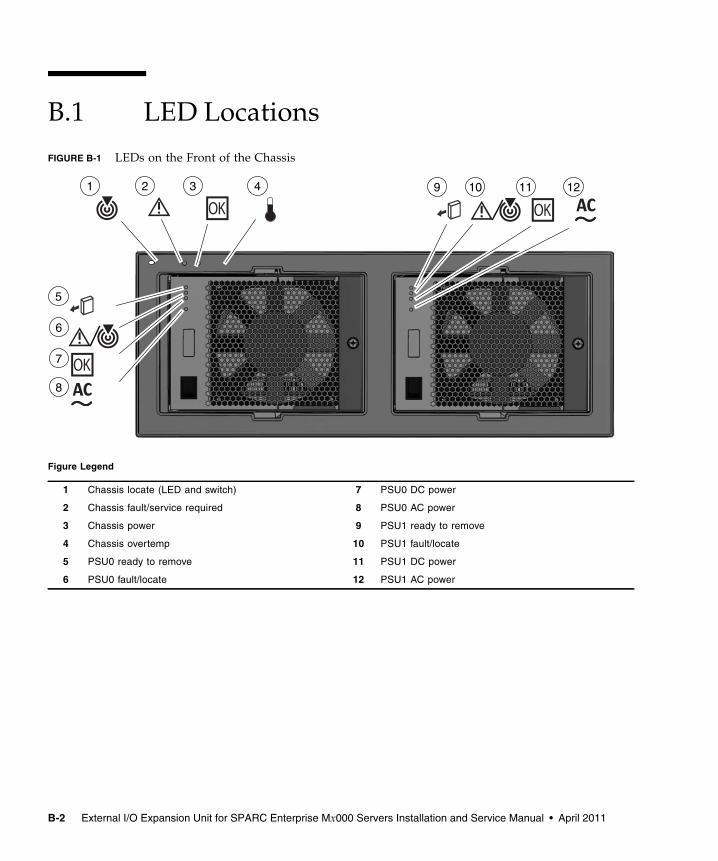
B.1 LED Locations
FIGURE B-1 LEDs on the Front of the Chassis
Figure Legend
1 Chassis locate (LED and switch) 7 PSU0 DC power
2 Chassis fault/service required 8 PSU0 AC power
3 Chassis power 9 PSU1 ready to remove
4 Chassis overtemp 10 PSU1 fault/locate
5 PSU0 ready to remove 11 PSU1 DC power
6 PSU0 fault/locate 12 PSU1 AC power
1 2 3 4
5
6
7
8
9 10 11 12
B-2 External I/O Expansion Unit for SPARC Enterprise Mx000 Servers Installation and Service Manual • April 2011

FIGURE B-2 LEDs on the Rear of the Chassis
Note – The Locate LED is a lighted push-button switch. When the flashing of itsLED has helped you to locate the External I/O Expansion Unit, turn off the LED bypressing the switch. Note that the LED will not turn off if you press less than 0.5seconds. You can also manually turn on the LED by pressing the button.
Figure Legend
1 Chassis locate (LED and switch) 8 I/O boat 1 ready to remove
2 Chassis fault/service required 9 I/O boat 1 fault/locate
3 Chassis power 10 I/O boat 1 DC power
4 Chassis overtemp 11 Link card data
5 I/O boat 0 ready to remove 12 Link card management
6 I/O boat 0 fault/locate 13 Slot attention/locate (all PCI carriers)
7 I/O boat 0 DC power 14 Slot power (all PCI carriers)
1 2 3 4
5 6 7
8 9 10
11
12
14
1311 12
Appendix B External I/O Expansion Unit LED Status Indicators B-3

B.2 LED States
Note – Text shown in bold font indicates the normal operating state for each LED.
TABLE B-1 External I/O Expansion Unit Chassis (Front)
LED Name Color State Meaning
Locate White OffFlash The unit is located here. (4 Hz) To turn off the flashing
LED, press the button for 0.5 second or longer.
Fault/service required Amber OffOn
No fault.Fault present.
Power Green OnOffFlash
Chassis power on, one or both boats on.Chassis power off.Chassis power on, all boats off (0.3 Hz)
Overtemp Amber OffOn
Temperature okay.Unit needs attention.
B-4 External I/O Expansion Unit for SPARC Enterprise Mx000 Servers Installation and Service Manual • April 2011

TABLE B-2 External I/O Expansion Unit Chassis (Rear)
LED Name Color State Meaning
Locate White OffFlash The unit is located here. (4 Hz) To turn off the flashing
LED, press the button for 0.5 second or longer.
Fault/service required Amber OffOn
No fault.Fault present.
OK Green OnOffFlash
Chassis power on, one or both boats on.Chassis power off.Chassis power on, all boats off (0.3 Hz)
Overtemp Amber OffOn
Temperature okay.Unit needs attention.
TABLE B-3 I/O Boat
LED Name Color State Meaning
Power Green OnOffFlash
Boat power on, and boat is managed.Boat power off.Boat power on, and boat is not managed.
Fault/Locate Amber OffOnFlash
No fault.Fault present.Locate on.
Ready to remove Blue OffOn
Not ready to remove.Ready to remove.
TABLE B-4 Power Supply Unit (PSU0 and PSU1)
LED Name Color State Meaning
Ready to remove Blue OffOn
Not ready to remove.Ready to remove.
Fault/Locate Amber OffOnFlash
No fault.Fault present.Locate on.
AC Power Green OnOff
AC input.No AC input.
DC Power Green OnOff
DC output.No DC output.
Appendix B External I/O Expansion Unit LED Status Indicators B-5

Note – On the optical link card, the LEDs for link card data and link cardmanagement are located next to the optical cable sockets. The LEDs do not have anydirect relationship to the sockets and are not intended to indicate the activity of theoptical cable sockets.
TABLE B-5 Carriers 1-6
LED Name Color State Meaning
Power*
* When the External I/O Expansion Unit is first powered on, a lighted Power LED means the slot has power. An unlighted Power LEDmeans the slot is not powered.
Green OnOffFlash
Card in slot.Slot empty.Power transition in progress.
Attention/Locate Amber OffOnFlash
No fault.Fault present.Locate on. (1 Hz)
TABLE B-6 Link Card (Optical Version)
LED Name Color State Meaning
Data (upper LED) Green OnOffFlash
x8 PCI Express links.Link is downs.x1 or x4 PCI Express link (degraded state). (1 Hz slow flash)
Management (lower LED) Green OnFlashOff
Management link is up. (Flashes in time with data traffic)Management link is down. (0.3 Hz very slow flash)Link card power is off.
TABLE B-7 Link Card (Copper Version)
LED Name Color State Meaning
Data (right LED) Green OnOffFlash
x8 PCI Express links.Link is down.x1 or x4 PCI Express link (degraded state). (1 Hz slow flash)
Management (left LED) Green OnFlashOff
Management link is up. (Flashes in time with data traffic)Management link is down. (0.3 Hz very slow flash)Link card power is off.
B-6 External I/O Expansion Unit for SPARC Enterprise Mx000 Servers Installation and Service Manual • April 2011

APPENDIX C
PCI Cards and Device Mapping
This appendix shows examples of device maps (device paths) for PCI cards in anExternal I/O Expansion Unit attached to a host system. Use this information toidentify and locate PCI cards in the External I/O Expansion Unit I/O boats.
Topics in this appendix include:
■ Section C.1, “Device Mapping” on page C-1
■ Section C.2, “Device Map Examples” on page C-3
■ Section C.3, “Software Commands for the External I/O Expansion Unit” onpage C-6
C.1 Device MappingWhen the host server is booted, the OpenBoot PROM creates a map of devicesinternal and external to the host server. When mapping the external devices, theOpenBoot PROM starts from the host’s I/O Unit (IOU) slots. For the External I/OExpansion Unit, the device map includes circuitry in the I/O boats, the PCI cards inthe I/O boats, and the external devices that are connected to the PCI cards.
Note – The External I/O Expansion Unit’s link cards and link cable do not appear inthe device map. When you install a link card in the host server, the OpenBoot PROMwill not detect that card. After you connect the link cable(s) between the link card inthe host server and the link card in an I/O boat, the OpenBoot PROM can detectcircuitry and any PCI cards in the I/O Boat.
The host server’s IOU slots are identified by various device path names such as/pci@x0,600000, /pci@x1,700000, /pci@x2,600000, and so forth. These namesvary according to the location of the I/O unit (IOU) in the host, and by the slotlocation in the I/O unit. For the IOU slot names, see TABLE C-1 and TABLE C-2.
C-1

TABLE C-1 lists the IOU slots in the SPARC Enterprise M4000/M5000 servers. Formore information about IOU slot names, refer to the discussions of I/O devicemapping in the SPARC Enterprise M4000/M5000/M8000/M9000 Servers AdministrationGuide.
TABLE C-2 lists the IOU slots in the SPARC Enterprise M8000/M9000 servers. Formore information about IOU slot names, refer to the discussions of I/O devicemapping in the SPARC Enterprise M4000/M5000/M8000/M9000 Servers AdministrationGuide.
The OpenBoot PROM maps several types of connecting devices inside the I/O boatsin the External I/O Expansion Unit. These connecting devices generally havemultiple I/O ports which appear in the OpenBoot PROM report as pci@0, pci@1,pci@0,1, and so forth. These connecting devices are switching circuits which switchbetween multiple inputs, and bridge circuits, which connect PCI-X buses to PCIExpress buses.
TABLE C-1 IOU Slots in SPARC Enterprise M4000/M5000 Servers
IOU Slot OpenBoot PROM Device Path Name
IOU Slot 0*
* Slot 0 is a PCI-X slot. The External I/O Expansion Unit link card cannot be used in this slot.
/pci@x0,600000/pci@0/pci@8/pci@0,1
IOU Slot 1 /pci@x0,600000/pci@0/pci@9
IOU Slot 2 /pci@x1,700000
IOU Slot 3 /pci@x2,600000
IOU Slot 4 /pci@x3,700000
TABLE C-2 IOU Slots in SPARC Enterprise M8000/M9000 Servers
IOU Slot OpenBoot PROM Device Path Name
IOU Slot 0 pci@x0,600000
IOU Slot 1 pci@x1,700000
IOU Slot 2 pci@x2,600000
IOU Slot 3 pci@x3,700000
IOU Slot 4 pci@x4,600000
IOU Slot 5 pci@x5,700000
IOU Slot 6 pci@x6,600000
IOU Slot 7 pci@x7,700000
C-2 External I/O Expansion Unit for SPARC Enterprise Mx000 Servers Installation and Service Manual • April 2011

C.2 Device Map ExamplesAs shown in the diagrams below, the OpenBoot PROM displays the following partsin sequence for each PCI card in an External I/O Expansion Unit:
■ The I/O Unit (IOU) slot in the server
■ Multiple devices inside the I/O boat
■ The PCI card in the I/O boat
■ Disk drives, SCSI ports, or networks that connect to the PCI card
C.2.1 Device Map for PCI Express CardsThis is an example of a complete device path for a PCI Express (PCIe) card in a PCIExpress boat:
IOU_slot is the IOU slot to which the link card for a External I/O Expansion Unit isconnected. See TABLE C-1 and TABLE C-2.
FIGURE C-1 shows the device path for a PCI Express card. The device path is theaccumulation of ports from the host data bus (item 1) to the PCI card (item 6).
FIGURE C-1 Device Path for PCI Express (PCIe) PCI Cards
/IOU_slot/pci@0/pci@9/pci@0/pci@9/abc@n
2 3 4 5 6
00 91 1
01
0
0
9
9 PCIe slot 6
PCIe slot 5
PCIe slot 4
PCIe slot 3
PCIe slot 2
PCIe slot 1
1a
1
Appendix C PCI Cards and Device Mapping C-3

C.2.2 Device Map for PCI-X CardsThis is an example of a complete device path for a PCI-X card in a PCI-X boat:
IOU_slot is the IOU slot to which the link card for a External I/O Expansion Unit isconnected. See TABLE C-1 and TABLE C-2.
FIGURE C-2 shows the device path for a PCI-X card. The device path is theaccumulation of ports from the IOU slot (item 1) to the PCI card (item 5).
TABLE C-3 Parts of a Device Path for a PCI Express I/O Boat
Item Description Device Tree Path Example
1 IOU slot /pci@xy,700000
1a link cards (Nothing is displayed for link cards. This is normal behavior.They are not visible to the OpenBoot PROM.)
2 /pci@0 /pci@xy,700000/pci@0
3 /pci@9 /pci@xy,700000/pci@0/pci@9
4 /pci@0 /pci@xy,700000/pci@0/pci@9/pci@0
5 /pci@9 /pci@xy,700000/pci@0/pci@9/pci@0/pci@9
6 PCI card /pci@xy,700000/pci@0/pci@9/pci@0/pci@9/abc@n
/IOU_slot/pci@0/pci@8/pci@0/abc@n
C-4 External I/O Expansion Unit for SPARC Enterprise Mx000 Servers Installation and Service Manual • April 2011

FIGURE C-2 Device Path for PCI-X PCI Cards
TABLE C-4 Parts of a Device Path for a PCI-X I/O Boat
Item Description Device Tree Path Example
1 IOU slot /pci@xy,700000
1a link cards (Nothing is displayed for link cards. This is normal behavior. They are notvisible to the OpenBoot PROM.)
2 /pci@0 /pci@xy,700000/pci@0
3 /pci@8 /pci@xy,700000/pci@0/pci@8
4 /pci@0 /pci@xy,700000/pci@0/pci@8/pci@0
5 PCI card /pci@xy,700000/pci@0/pci@8/pci@0,1/abc@n
0 891
PCI-X slot 6
PCI-X slot 5
PCI-X slot 4
PCI-X slot 3
PCI-X slot 2
PCI-X slot 1
0
0,1
0
0,1
0
0,1
2 3 4 5
1a
1
Appendix C PCI Cards and Device Mapping C-5

C.3 Software Commands for the ExternalI/O Expansion UnitFrom the host server, you can use the following commands to identify and locate thePCI cards in the I/O boats:
For the following examples of program output, assume an External I/O ExpansionUnit has one PCI Express boat and one PCI-X boat. The boats contain six PCI cardseach:
TABLE C-5 Diagnostic and Maintenance Commands
Command Comments Reference
ioxadm (8) The ioxadm (8) command displays information about the ExternalI/O Expansion Unit. System administrators and service personnelcan use ioxadm to manage External I/O Expansion Unit functions.
TABLE C-7
show-devs Displays device tree information for PCI cards and other devicesattached to the host. Run this command from the OpenBoot prompt.
EXAMPLE C-1
cfgadm (1M) The cfgadm (1M) command displays dynamic reconfigurationinformation for a system. Run this command from the Oracle Solarissuperuser prompt.
EXAMPLE C-2
prtdiag (1M) The prtdiag (1M) command displays system configuration and anyfailed field replaceable units (FRUs). Run this command from theOracle Solaris superuser prompt.
EXAMPLE C-3
TABLE C-6 PCI Cards in a Typical External I/O Expansion Unit
Boat Slot PCI Card
PCI Express boat 1 Dual gigabit Ethernet
2 Dual gigabit Ethernet
3 Dual gigabit Ethernet
4 4 gigabit fibre channel
5 Dual 4 gigabit fibre channel
6 Dual 4 gigabit fibre channel
PCI-X boat 1 Quad gigabit Ethernet
2 4 gigabit fibre channel
3 Gigaswift gigabit Ethernet
C-6 External I/O Expansion Unit for SPARC Enterprise Mx000 Servers Installation and Service Manual • April 2011

C.3.1 The ioxadm CommandUse the ioxadm (8) command to display information about the External I/OExpansion Unit and to manage External I/O Expansion Unit functions. The ioxadmcommand is executed on the service processor of the host system.
The ioxadm command has three levels of user privileges: platop (platform operatoror user), platadm (platform administrator), fieldeng (service or field engineer) Theuser’s privilege level is set through the setprivileges (8) command.
Refer to the ioxadm (8) man page for more information.
4 Dual Ultra320 SCSI adapter
5 Dual gigabit Ethernet
6 4 gigabit fibre channel
TABLE C-7 ioxadm Privileges and Commands
Required Privilege Command Description
fieldeng, platadm, platop ioxadm env Display the environmental state of the ExternalI/O Expansion Unit or link card.
fieldeng, platadm, platop ioxadm list List information about the External I/O ExpansionUnit, links, and External I/O Expansion UnitFRUs.
fieldeng, platadm ioxadm locator Display and set the status of the locator LED.
fieldeng, platadm ioxadm poweroff Power down External I/O Expansion Unit FRUsfor replacement.
fieldeng, platadm ioxadm poweron Return an External I/O Expansion Unit FRU tonormal operation after being powered off.
fieldeng ioxadm reset Reinitialize External I/O Expansion Unit FRUs.
fieldeng ioxadm setled Set the state of External I/O Expansion Unit LEDs.
TABLE C-6 PCI Cards in a Typical External I/O Expansion Unit (Continued)
Boat Slot PCI Card
Appendix C PCI Cards and Device Mapping C-7

C.3.2 The show-devs CommandThe show-devs command displays the paths from the host system to the PCI cardsin the I/O boat.
EXAMPLE C-1 Typical Output of the show-devs Command (1 of 3)
{0} ok show-devs
/pci@3,700000
/pci@2,600000
/pci@1,700000
/pci@0,600000
/pci@8,4000
/cmp@408,0
/cmp@400,0
/pseudo-mc@200,200
/nvram
/pseudo-console
/virtual-memory
/memory@m3c000000000
/aliases
/options
/openprom
/chosen
/packages
/pci@3,700000/pci@0
/pci@3,700000/pci@0/pci@9
/pci@3,700000/pci@0/pci@8
/pci@3,700000/pci@0/pci@1
/pci@3,700000/pci@0/pci@9/pci@0,1
/pci@3,700000/pci@0/pci@9/pci@0
/pci@3,700000/pci@0/pci@9/pci@0,1/scsi@4,1
/pci@3,700000/pci@0/pci@9/pci@0,1/scsi@4
/pci@3,700000/pci@0/pci@9/pci@0/network@4
/pci@3,700000/pci@0/pci@8/pci@0,1
/pci@3,700000/pci@0/pci@8/pci@0
/pci@3,700000/pci@0/pci@8/pci@0,1/SUNW,qlc@4,1
/pci@3,700000/pci@0/pci@8/pci@0,1/SUNW,qlc@4
/pci@3,700000/pci@0/pci@8/pci@0,1/SUNW,qlc@4,1/fp@0,0
/pci@3,700000/pci@0/pci@8/pci@0,1/SUNW,qlc@4,1/fp@0,0/disk
/pci@3,700000/pci@0/pci@8/pci@0,1/SUNW,qlc@4/fp@0,0
/pci@3,700000/pci@0/pci@8/pci@0,1/SUNW,qlc@4/fp@0,0/disk
/pci@3,700000/pci@0/pci@8/pci@0/pci@4
/pci@3,700000/pci@0/pci@8/pci@0/pci@4/scsi@2,1
/pci@3,700000/pci@0/pci@8/pci@0/pci@4/scsi@2
C-8 External I/O Expansion Unit for SPARC Enterprise Mx000 Servers Installation and Service Manual • April 2011

/pci@3,700000/pci@0/pci@8/pci@0/pci@4/network@1
/pci@3,700000/pci@0/pci@8/pci@0/pci@4/network@0
/pci@3,700000/pci@0/pci@8/pci@0/pci@4/scsi@2,1/tape
/pci@3,700000/pci@0/pci@8/pci@0/pci@4/scsi@2,1/disk
/pci@3,700000/pci@0/pci@8/pci@0/pci@4/scsi@2/tape
/pci@3,700000/pci@0/pci@8/pci@0/pci@4/scsi@2/disk
/pci@3,700000/pci@0/pci@1/pci@0,1
/pci@3,700000/pci@0/pci@1/pci@0
/pci@3,700000/pci@0/pci@1/pci@0,1/SUNW,qlc@4,1
/pci@3,700000/pci@0/pci@1/pci@0,1/SUNW,qlc@4
/pci@3,700000/pci@0/pci@1/pci@0,1/SUNW,qlc@4,1/fp@0,0
/pci@3,700000/pci@0/pci@1/pci@0,1/SUNW,qlc@4,1/fp@0,0/disk
/pci@3,700000/pci@0/pci@1/pci@0,1/SUNW,qlc@4/fp@0,0
/pci@3,700000/pci@0/pci@1/pci@0,1/SUNW,qlc@4/fp@0,0/disk
/pci@3,700000/pci@0/pci@1/pci@0/pci@4
/pci@3,700000/pci@0/pci@1/pci@0/pci@4/pci@4
/pci@3,700000/pci@0/pci@1/pci@0/pci@4/pci@0
/pci@3,700000/pci@0/pci@1/pci@0/pci@4/pci@4/network@3
/pci@3,700000/pci@0/pci@1/pci@0/pci@4/pci@4/network@2
/pci@3,700000/pci@0/pci@1/pci@0/pci@4/pci@0/network@1
/pci@3,700000/pci@0/pci@1/pci@0/pci@4/pci@0/network@0
/pci@2,600000/pci@0
/pci@2,600000/pci@0/pci@9
/pci@2,600000/pci@0/pci@8
/pci@2,600000/pci@0/pci@1
/pci@2,600000/pci@0/pci@9/pci@0
/pci@2,600000/pci@0/pci@9/pci@0/pci@9
/pci@2,600000/pci@0/pci@9/pci@0/pci@1
/pci@2,600000/pci@0/pci@9/pci@0/pci@0
/pci@2,600000/pci@0/pci@9/pci@0/pci@9/fibre-channel@0,1
/pci@2,600000/pci@0/pci@9/pci@0/pci@9/fibre-channel@0
/pci@2,600000/pci@0/pci@9/pci@0/pci@1/fibre-channel@0,1
/pci@2,600000/pci@0/pci@9/pci@0/pci@1/fibre-channel@0
/pci@2,600000/pci@0/pci@9/pci@0/pci@0/QLGC,qlc@0,1
/pci@2,600000/pci@0/pci@9/pci@0/pci@0/QLGC,qlc@0
/pci@2,600000/pci@0/pci@9/pci@0/pci@0/QLGC,qlc@0,1/fp@0,0
/pci@2,600000/pci@0/pci@9/pci@0/pci@0/QLGC,qlc@0,1/fp@0,0/disk
/pci@2,600000/pci@0/pci@9/pci@0/pci@0/QLGC,qlc@0/fp@0,0
/pci@2,600000/pci@0/pci@9/pci@0/pci@0/QLGC,qlc@0/fp@0,0/disk
/pci@2,600000/pci@0/pci@1/pci@0
/pci@2,600000/pci@0/pci@1/pci@0/pci@9
/pci@2,600000/pci@0/pci@1/pci@0/pci@1
/pci@2,600000/pci@0/pci@1/pci@0/pci@0
EXAMPLE C-1 Typical Output of the show-devs Command (2 of 3)
Appendix C PCI Cards and Device Mapping C-9

/pci@2,600000/pci@0/pci@1/pci@0/pci@9/network@0,1
/pci@2,600000/pci@0/pci@1/pci@0/pci@9/network@0
/pci@2,600000/pci@0/pci@1/pci@0/pci@1/network@0,1
/pci@2,600000/pci@0/pci@1/pci@0/pci@1/network@0
/pci@2,600000/pci@0/pci@1/pci@0/pci@0/network@0,1
/pci@2,600000/pci@0/pci@1/pci@0/pci@0/network@0
/pci@0,600000/pci@0
/pci@0,600000/pci@0/pci@9
/pci@0,600000/pci@0/pci@8
/pci@0,600000/pci@0/pci@1
/pci@0,600000/pci@0/pci@8/pci@0,1
/pci@0,600000/pci@0/pci@8/pci@0
/pci@0,600000/pci@0/pci@8/pci@0/pci0,0@7
/pci@0,600000/pci@0/pci@8/pci@0/network@2,1
/pci@0,600000/pci@0/pci@8/pci@0/network@2
/pci@0,600000/pci@0/pci@8/pci@0/scsi@1
/pci@0,600000/pci@0/pci@8/pci@0/scsi@1/disk
/pci@0,600000/pci@0/pci@8/pci@0/scsi@1/tape
/pci@8,4000/ebus@1
/pci@8,4000/ebus@1/panel@14,280030
/pci@8,4000/ebus@1/scfc@14,200000
/pci@8,4000/ebus@1/serial@14,400000
/pci@8,4000/ebus@1/flashprom@10,0
/cmp@408,0/core@1
/cmp@408,0/core@0
/cmp@408,0/core@1/cpu@1
/cmp@408,0/core@1/cpu@0
/cmp@408,0/core@0/cpu@1
/cmp@408,0/core@0/cpu@0
/cmp@400,0/core@1
/cmp@400,0/core@0
/cmp@400,0/core@1/cpu@1
/cmp@400,0/core@1/cpu@0
/cmp@400,0/core@0/cpu@1
/cmp@400,0/core@0/cpu@0 /openprom/client-services
/packages/obp-tftp
/packages/terminal-emulator
/packages/disk-label
/packages/deblocker
/packages/SUNW,builtin-drivers
{0} ok
EXAMPLE C-1 Typical Output of the show-devs Command (3 of 3)
C-10 External I/O Expansion Unit for SPARC Enterprise Mx000 Servers Installation and Service Manual • April 2011

C.3.3 The cfgadm CommandThe cfgadm command displays devices connected to the main server bus. To use thiscommand, refer to the cfgadm (1M) man page.
This is typical output of the cfgadm command;
EXAMPLE C-2 Typical Output of the cfgadm Command (1 of 2)
# cfgadm -laAp_Id Type Receptacle Occupant ConditionSB0 System_Brd connected configured okSB0::cpu0 cpu connected configured okSB0::cpu1 cpu connected configured okSB0::memory memory connected configured okSB0::pci0 io connected configured okSB0::pci1 io connected configured okSB0::pci2 io connected configured okSB0::pci3 io connected configured okSB0::pci8 io connected configured okSB1 disconnected unconfigured unknownSB2 disconnected unconfigured unknown...SB14 disconnected unconfigured unknownSB15 disconnected unconfigured unknownc0 scsi-bus connected configured unknownc0::dsk/c0t0d0 disk connected configured unknownc0::dsk/c0t1d0 disk connected configured unknownc0::dsk/c0t3d0 CD-ROM connected configured unknownc0::rmt/0 tape connected configured unknownc1 fc-fabric connected configured unknownc1::2100000c5062606a disk connected configured unknownc2 fc-fabric connected configured unknownc2::2100000c50628015 disk connected configured unknown...c14::dsk/c14t11d0 disk connected configured unknownc14::es/ses1 processor connected configured unknowniou#0-pci#1 unknown empty unconfigured unknowniou#0-pci#2 unknown empty unconfigured unknowniou#0-pci#3 pci-pci/hp connected configured okiou#0-pci#4 pci-pci/hp connected configured okpci1 pci-pci/hp connected configured okpci2 fibre/hp connected configured okpci3 etherne/hp connected configured okpci4 scsi/hp connected configured okpci5 pci-pci/hp connected configured okpci6 fibre/hp connected configured okpcie1 etherne/hp connected configured okpcie2 etherne/hp connected configured ok
Appendix C PCI Cards and Device Mapping C-11
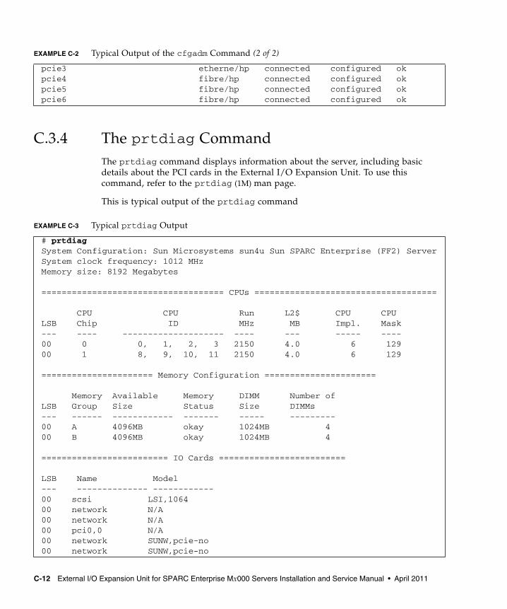
C.3.4 The prtdiag CommandThe prtdiag command displays information about the server, including basicdetails about the PCI cards in the External I/O Expansion Unit. To use thiscommand, refer to the prtdiag (1M) man page.
This is typical output of the prtdiag command
pcie3 etherne/hp connected configured okpcie4 fibre/hp connected configured okpcie5 fibre/hp connected configured okpcie6 fibre/hp connected configured ok
EXAMPLE C-3 Typical prtdiag Output
# prtdiagSystem Configuration: Sun Microsystems sun4u Sun SPARC Enterprise (FF2) ServerSystem clock frequency: 1012 MHzMemory size: 8192 Megabytes
==================================== CPUs ====================================
CPU CPU Run L2$ CPU CPULSB Chip ID MHz MB Impl. Mask--- ---- -------------------- ---- --- ----- ----00 0 0, 1, 2, 3 2150 4.0 6 12900 1 8, 9, 10, 11 2150 4.0 6 129
====================== Memory Configuration ======================
Memory Available Memory DIMM Number ofLSB Group Size Status Size DIMMs--- ------ ------------ ------- ----- ---------00 A 4096MB okay 1024MB 400 B 4096MB okay 1024MB 4
========================= IO Cards =========================
LSB Name Model--- -------------- ------------00 scsi LSI,106400 network N/A00 network N/A00 pci0,0 N/A00 network SUNW,pcie-no00 network SUNW,pcie-no
EXAMPLE C-2 Typical Output of the cfgadm Command (2 of 2)
C-12 External I/O Expansion Unit for SPARC Enterprise Mx000 Servers Installation and Service Manual • April 2011

00 network SUNW,pcie-no00 network SUNW,pcie-no00 network SUNW,pcie-no00 network SUNW,pcie-no00 fp N/A00 network SUNW,pcie-no00 network SUNW,pcie-no00 network SUNW,pcie-no00 network SUNW,pcie-no00 network SUNW,pcie-no00 network SUNW,pcie-no00 fp N/A00 network SUNW,pci-qge00 network SUNW,pci-qge00 network SUNW,pci-qge00 network SUNW,pci-qge00 fp N/A
EXAMPLE C-3 Typical prtdiag Output
Appendix C PCI Cards and Device Mapping C-13

C-14 External I/O Expansion Unit for SPARC Enterprise Mx000 Servers Installation and Service Manual • April 2011

APPENDIX D
Troubleshooting
This appendix includes these topics for the External I/O Expansion Unit from Oracleand Fujitsu:
■ Section D.1, “Using Hardware Symptoms to Troubleshoot Problems” on page D-2
■ Section D.2, “Using Manual Techniques of Fault Isolation to Diagnose ErrorMessages” on page D-4
D-1

D.1 Using Hardware Symptoms toTroubleshoot Problems
TABLE D-1 Troubleshooting (1 of 3)
Area Symptom Comments
Carrier Carrier does not seat. • Pull the carrier handle out fully before inserting the carrier inthe I/O boat slot. The PCI card and carrier plate will strike thecard socket if the handle is not fully retracted.
• The carrier is not correctly seated in the upper or lower cardguide.
• A type C lock is in the wrong location and is hitting the cardsocket.
Carrier handle requiresexcessive pressure to close.
• The PCI card is not mounted correctly on the carrier. If the PCIcard is tilted by even a small angle on the carrier, it might notseat correctly.
• The PCI card does not fit the socket. The card might be theincorrect type for the I/O boat. (Note that the PCI-X cardsocket is approximately twice the length of a PCI Expresssocket.)
• The PCI Express boat does not accept x16 PCI Express cards.This boat accepts only x8 PCI Express cards or smaller.
Link A link problem is suspected. • Ordering a complete set of replacements at one time canshorten the troubleshooting process. If you cannot determine ifa link problem is caused by a link card or a link cable, orderreplacement link cards for the host and the I/O boat, alongwith a copper link cable or two optical link cables, asappropriate.
Service processor does notdetect External I/OExpansion Unit.
• The host PCI Express slot containing the link card must bepowered on. The host service processor communicates with I2Cdevices in the External I/O Expansion Unit through the linkcards and cable. Verify that the domain is powered on and thatthe link card in the host slot is fully seated.
• If the host link card is added to a running domain, seeSection 4.13, “Powering Up a Link After Service” on page 4-32to power on the PCI Express slot.
D-2 External I/O Expansion Unit for SPARC Enterprise Mx000 Servers Installation and Service Manual • April 2011

• If PCI Express data path failures are detected during initialPower-On Self Test (POST), POST will turn off power to thelink card slot in the host. FRUs in the External I/O ExpansionUnit are detected by the host service processor during POSTbut disappear when power to the slot is removed. Reseat thelink cards in the host and External I/O Expansion Unit, checkcables, or try a different PCI Express slot in the host.
Host Host or service processordoes not recognize PCI cardor cards.
• For the optical link kit, the link cables might be reversed. TheTX socket on each link card should connect to the RX socket onthe other link card. Note that each optical cable connects a TXsocket to an RX socket.
• The PCI card might not be seated completely. Remove the cardand carrier and verify that the card is properly attached to thecarrier. See PCI card in this table.
LEDs • See Appendix B for LED information.
PSU Fan does not turn on, LEDsdo not light.
• The PSU is not receiving DC current from the second PSU.Note: The PSUs share DC current, so the fan and LEDs shouldoperate if the second PSU is running normally.
• Verify that the PSU is seated. Close the PSU handle and tightenthe handle locking screw.
The fan operates, but thePSU does not come on line.
• The PSU might not have AC input. Note: The PSUs share DCcurrent, but do not share AC current. Verify that both of theinternal AC cables are connected to AC voltage through theAC cords supplied with the External I/O Expansion Unit(FIGURE 2-11).
• Check external circuit breakers.• PSU AC switches must be in the on position.
PCI card PCI card or carrier is difficultto seat in the boat, or thecard moves out of positionon carrier.
• The card locks might be loose, allowing the card to tilt.Reposition the card and tighten the card locks. It is mostimportant that the card lock(s) at the back* of the card presstightly against the back of the card.
• Excessive pressure on the card locks might have bent the cardbracket (FIGURE 1-21).
• If PCI Express data path failures are detected during initialPower-On Self Test (POST), POST will turn off power to thelink card slot in the host. FRUs in the External I/O ExpansionUnit are detected by the host service processor during POSTbut disappear when power to the slot is removed. Reseat thelink cards in the host and External I/O Expansion Unit, checkcables, or try a different PCI Express slot in the host.
TABLE D-1 Troubleshooting (2 of 3)
Area Symptom Comments
Appendix D Troubleshooting D-3

D.2 Using Manual Techniques of FaultIsolation to Diagnose Error MessagesSome faults cannot be isolated to a single FRU without performing manual steps tohelp isolate the problem. For these types of failures, the fault diagnosis includesmultiple FRUs in the fault list.
The following sections provide additional details and suggested steps to locate theproblem FRU.
D.2.1 Error Messages and Fault Managed ResourceIdentifiersWhen a fault is diagnosed, a message is displayed on the console log. For example:
The fmdump utility can be used to retrieve fault diagnosis details associated with afault event:
• The card might not fit the socket in the boat. The card might bethe wrong type for the PCI Express or PCI-X socket.
• Verify that there is no broken plastic lying inside the socket.
PCI card is difficult to installon the carrier.
• The top of the card bracket must fit over the alignment postinside the carrier front housing (FIGURE 1-23).
• The bottom of the card bracket might be hooked behind theRFI gasket inside the carrier front housing (FIGURE 1-24).
• The bottom of the card may be hitting the alignment tab at thebottom front of the carrier (lower detail in FIGURE 1-22).
* This refers to the horizontally-sliding card lock(s). The fitting of the vertically-sliding card lock(s) are less critical.
Sep 15 13:05:53 burl-m4000-0 fmd: SOURCE: sde, REV: 1.16, CSN:0000000000 EVENT-ID: 1a56dc98-aa6d-4128-adaf-428d45fcb024 Referto URL/msg/IOXSCF-8000-CQ for detailed information.
XSCF> fmdump -v -u event-id
TABLE D-1 Troubleshooting (3 of 3)
Area Symptom Comments
D-4 External I/O Expansion Unit for SPARC Enterprise Mx000 Servers Installation and Service Manual • April 2011

where event-id is the event ID displayed in the fault message.
Each diagnosis lists one or more fault suspects represented by fault managedresource identifiers (FMRIs). The FMRI may represent a component in a FRU, theFRU itself, or a bus segment within a FRU.
Note – The letters hc in an error message usually refer to a hardware component. Lookfor the string hc:/// to identify a suspected hardware component.
The following example shows the fault diagnosis for an I2C access failure for the LEDcontroller for PSU 1:
XSCF> fmdump -v -u 1a56dc98-aa6d-4128-adaf-428d45fcb024TIME UUID MSG-IDSep 15 13:05:53.8069 1a56dc98-aa6d-4128-adaf-428d45fcb024 IOXSCF-8000-CQ 25% fault.chassis.iox.i2c.device
Problem in: hc:///iox=983555/ps=1/ledctrl=0 Affects: hc:///iox=983555/ps=1/ledctrl=0 FRU: hc://:product-id=SPARC Enterprise M4000 :chassis-id=0000000000:server-id=burl-m4000-0:serial=DD0566:part=CF003001701\3001701:revision=04/component=IOX@X084/PS1 Location: IOX@X084/PS1
25% fault.chassis.iox.i2c.bus
Problem in: hc:///iox=983555/iob=0/i2c_local=0 Affects: hc:///iox=983555/iob=0/i2c_local=0 FRU: hc://:product-id=SPARC Enterprise M4000 :chassis-id=0000000000:server-id=burl-m4000-0:serial=1E0041:part=5016939:revision=03/component=IOX@X084/IOB0 Location: IOX@X084/IOB0
25% fault.chassis.iox.i2c.bus
Problem in: hc:///iox=983555/ps=1/i2c_local=0 Affects: hc:///iox=983555/ps=1/i2c_local=0 FRU: hc://:product-id=SPARC Enterprise M4000 :chassis-id=0000000000:server-id=burl-m4000-0:serial=DD0566:part=CF003001701\3001701:revision=04/component=IOX@X084/PS1 Location: IOX@X084/PS1
25% fault.chassis.iox.i2c.bus
Problem in: hc:///iox=983555/i2c_a=0
Appendix D Troubleshooting D-5

In the example above, the MSG-ID is IOXSCF-8000-CQ.
The FMRIs are:
■ hc:///iox=983555/ps=1/ledctrl=0
(the I2C device in PSU IOX@X084/PS1)
■ hc:///iox=983555/iob=0/i2c_local=0
(the I2C bus segment in boat IOX@X084/IOB0)
■ hc:///iox=983555/ps=1/i2c_local=0
(the I2C bus segment in PSU IOX@X084/PS1)
■ hc:///iox=983555/i2c_a=0
(the I2C bus segment in centerplane IOX@X084)
The following sections provide additional details and suggested steps to locate theproblem FRU.
If you must replace the FRU to solve the problem:
1. Refer to the SPARC Enterprise M3000/M4000/M5000/M8000/M9000 Servers XSCFUser’s Guide for details on using the poweron(8) and poweroff(8) commandsto power domains on and off.
2. Refer to Chapter 4 of this document for details on removing and replacingspecific FRUs within the External I/O Expansion Unit.
D.2.2 I2C Failures
There are multiple I2C bus topologies in the External I/O Expansion Unit. Some I2Cbuses are contained within a single FRU, while other I2C buses span multiple FRUs.
If the failure is on a bus contained within a single FRU, the identified FRU is faultyand must be replaced. See Section D.2.2.1, “I2C Fault Isolated to a Single FRU” onpage D-7
Affects: hc:///iox=983555/i2c_a=0 FRU: hc://:product-id=SPARC Enterprise M4000 :chassis-id=0000000000:server-id=burl-m4000-0:serial=XCX084:part=CF005016937\5016937:revision=03/component=IOX@X084 Location: IOX@X084
MSGID IOXSCF-8000-DE fault.chassis.iox.i2c.busMSGID IOXSCF-8000-CQ fault.chassis.iox.i2c.bus fault.chassis.iox.i2c.device
D-6 External I/O Expansion Unit for SPARC Enterprise Mx000 Servers Installation and Service Manual • April 2011

If the failure is on a bus that spans multiple FRUs, follow the suggested steps inSection D.2.2.2, “I2C Fault Spanning Multiple FRUs” on page D-7 to isolate theproblem FRU.
If the failure is in the host, see Section D.2.2.3, “I2C Fault When Accessing the LinkCard Installed in the Host” on page D-11.
D.2.2.1 I2C Fault Isolated to a Single FRU
If the fault list shows a single FRU as suspect, replace the FRU. The centerplane inthe chassis and the link cards each contain an I2C bus fully contained within the FRU.
Possible Causes
Faulty centerplane or link card.
Solutions■ If the problem is in hc:///iox=box_instance/i2c_c=0, then replace the chassis
(IOX@nnnn).
■ If the problem is in hc:///iox=box_instance/iob=x/link=0/i2c_local=0,then replace this link card (IOX@nnnn/IOBx/LINK).
■ If the problem is in hc:///chassis=0/iou=x/pcislot=y/link=0/i2c_local=0, then replace this link card (IOU#x-PCI#y).
D.2.2.2 I2C Fault Spanning Multiple FRUs
There are three I2C bus trees in the External I/O Expansion Unit that span multipleFRUs. They are identified on the centerplane as described in the following table.
TABLE D-1 Multiple FRUs Covered in I2C Buses
I2C Bus Tree FRUs Covered in I2C Bus
hc:///iox=box_instance/i2c_a=0 Spans the centerplane, PSU 1, and boat 0
hc:///iox=box_instance/i2c_b=0 Spans the centerplane, PSU 0, and boat 1
hc:///iox=box_instance/i2c_main=0 Spans all the FRUs: the centerplane, bothPSUs, both boats, and the link cardsinstalled in the boats
Appendix D Troubleshooting D-7

Possible Causes■ There is a power design issue where an I2C hot-swap buffer may prevent
communication to I2C devices in a PSU.
■ A FRU is not fully seated.
■ A FRU is faulty.
Resolution
Contact a certified service technician for assistance in selecting one of the followingalternative methods for testing the I2C power design issue in the External I/OExpansion Unit.
■ PSU method: go to Step 1. This method can be performed while domains arerunning.
■ Power cord method: go to Step 2. This method cannot be performed whiledomains are running.
1. Use the PSU method to determine if the I2C buffer power design issue is atfault:
Caution – Do not power down more than one PSU at a time for this test, or datamight be lost.
a. Prepare the PSU for removal:
The blue PSU Ready to Remove LED lights to show the PSU status and to helpyou find the PSU.
b. Power off the PSU at the External I/O Expansion Unit.
c. When the PSU DC Power LED turns off, unlock the PSU handle and pull thePSU partway out of the slot.
Approximately 2 in./50 mm is a safe distance.
d. Wait 10 seconds.
e. Plug the PSU back into the slot and lock the PSU handle.
f. Power on the PSU.
If the problem has been corrected, the fault messages will not appear.
g. If this workaround corrects the problem, you do not have to do anythingmore to resolve this issue.
XSCF> ioxadm poweroff IOX@xxxx/PSy
D-8 External I/O Expansion Unit for SPARC Enterprise Mx000 Servers Installation and Service Manual • April 2011

h. If this workaround does not correct the problem, repeat Step a through Step ffor the remaining PSU.
i. If fault messages continue to appear, go to Step 3.
2. Use the power cord method to determine if the I2C buffer power design issue isat fault:
a. Power off the affected domains.
b. Power off both PSUs on the External I/O Expansion Unit.
c. When the DC Power LEDs on both PSUs turn off, disconnect both AC cords.
d. After 10 seconds or more, reconnect the AC cords.
e. Power on the PSUs in the External I/O Expansion Unit.
f. Power on the affected domains.
If the problem has been corrected, the fault messages will not appear.
g. If this workaround corrects the problem, you do not have to do anythingmore to resolve this issue.
h. If this workaround does not correct the problem, go to Step 3.
3. Determine if a FRU is not fully seated in the External I/O Expansion Unit:
a. Power off the affected domains.
b. Power off both PSUs.
c. Reseat all FRUs.
Remove and reinsert the following:
i. Both PSUs
ii. Both I/O boats
iii. Link cards in the I/O boats
d. Power on the PSUs.
e. Power on the affected domains.
If the problem has been corrected, the fault messages will not appear.
f. If reseating the FRUs corrects the problem, you do not have to do anythingmore to resolve this issue.
g. If reseating the FRUs does not correct the problem, go to Step 4.
Appendix D Troubleshooting D-9

4. If the fault list in the error message includes i2c_a or i2c_b, use the followingsteps to find the faulty FRU.
If the fault list does not include i2c_a or i2c_b, go to Step 5.
a. Power off the affected domains.
b. Power off both PSUs.
c. Swap the two PSUs with each other.
d. Power on the affected domains.
■ If the problem follows the PSU, replace the PSU. This should correct theproblem.
■ If the problem does not follow the PSU (if the same fault list is diagnosed),go to Step e to test the I/O boats.
e. Power off the affected domains.
f. Swap the I/O boats with each other.
If there is only one I/O boat, move it to the unused I/O boat slot.
g. Power on the affected domains.
■ If the problem follows the I/O boat, replace the I/O boat. This should correctthe problem.
■ If the problem does not follow the I/O boat (if the same fault list isdiagnosed after swapping the PSUs and the I/O boats), go to Step h.
h. If the fault continues after you have replaced the PSUs and I/O boat(s),replace the chassis.
5. If the fault list in the error message includes iox=box_instance/i2c_main=0,find the faulty FRU:
a. Power off the domains that use the FRUs and remove one FRU.
i. Power off the affected domains.
ii. Power off both PSUs.
iii. Remove a single FRU.
Following is the list of FRUs to remove for this procedure. Remove only oneFRU from this list each time you go through this procedure. If the problempersists, remove a different FRU from the list below using this sameprocedure:
-- PSU 0
-- PSU 1
-- I/O boat 0
D-10 External I/O Expansion Unit for SPARC Enterprise Mx000 Servers Installation and Service Manual • April 2011

-- I/O boat 1
Test the FRUs listed above before suspecting the following:
-- Link card (see Step b)
-- Chassis (see Step c)
iv. Power on both PSUs.
v. Power on the affected domains.
If the problem has been corrected, the fault messages will not appear.
vi. If this does not correct the problem, reinsert the FRU you removed inStep iii, then repeat Step i through Step v for a different FRU.
vii. If this corrects the problem, go to Step b.
viii. If this does not correct the problem, go to Step c.
b. Determine which FRU is causing the problem.
■ If the I2C problems are resolved by the removal of a PSU, assume the PSU isfaulty.
■ If the problems are resolved by removing an I/O boat, determine whetherthe problem is with the I/O boat itself or the link card in the I/O boat. Swapthe link card from the failed I/O boat to a known good I/O boat todetermine if the problem follows the link card.
c. If the errors continue to appear, either the chassis is faulty or multiple FRUshave I2C problems.
Contact a technical support engineer for advanced assistance.
D.2.2.3 I2C Fault When Accessing the Link Card Installed in the Host
The host manages the External I/O Expansion Unit through I2C commands sent tothe link card installed in a host PCI Express add-in card slot. If the fault list includesthe i2c_main bus for the link card installed in a host add-in slot hc:///chassis=0/iou=x/pcislot=y/link=0/i2c_main=0, a problem exists between the ExternalI/O Expansion Unit and the link card.
Possible Causes■ The host link card is not fully seated.
■ The host PCI Express slot is faulty.
■ The host link card is faulty.
Appendix D Troubleshooting D-11

Resolution
1. Reseat the host link card.
■ If this step corrects the problem, you do not have to do anything more toresolve this issue.
■ If this step does not correct the problem, and an empty slot is available in theserver IOU, go to Step 2.
■ If an empty slot is not available, go to Step 3.
2. Move the host link card to a different slot.
■ If the problem follows the card, replace the card.
■ If the problem does not recur, the IOU slot is faulty. Replace the IOU.
3. If no vacant slot is available in the host, swap the link card in the host with thelink card in the I/O boat.
■ If the error information changes, replace the link card that you moved from theserver IOU to the I/O boat.
■ If the error information continues unchanged, go to Step 4.
4. Install a known good link card in the host.
■ If the error information continues unchanged, replace the IOU in the host.
D.2.3 Management Bus Failures
A low-speed serial bus known as the management bus is used to send and receiveI2C commands to devices in the External I/O Expansion Unit. The bus uses side-band signals in the PCI Express cable and consists of a pair of link cards and thecable.
If there is a failure in the management bus, the system will not be able to discoverFRUs, gather environmental readings, or process alarm conditions and hardwarestate-changes for the devices accessed through the management bus.
Possible Causes■ The Bridge Controller is timing out.
■ The link cable has failed or is unplugged.
MSGID IOXSCF-8000-6H fault.chassis.iox.device.comMSGID IOXSCF-8000-7D fault.chassis.iox.device.com fault.chassis.iox.device.fail
D-12 External I/O Expansion Unit for SPARC Enterprise Mx000 Servers Installation and Service Manual • April 2011

■ A link card has failed.
Resolution
1. See Section D.2.7.4, “Bridge Controller Timeout” on page D-21 for details onBridge Controller timeouts.
2. Replace the link cable.
3. Replace the link card in the I/O boat.
4. Replace the link card in the host.
D.2.4 Cable Removed or Power Loss
The service processor detects loss of both the management bus and PCI Express datapath to an External I/O Expansion Unit. This failure occurs only if the host wasalready managing External I/O Expansion Unit. See Section D.2.6, “FRU DiscoveryFailures” on page D-15 for details on FRU discovery failures.
Possible Causes■ The PCI Express cable is unplugged.
■ There is a loss of input power to the External I/O Expansion Unit.
■ The I/O boat was removed while in use.
■ The cable is faulty.
■ The link card in the host is faulty.
■ The link card in the I/O boat is faulty.
Resolution
1. Check the cable connection.
If cable had been unplugged, make sure the link cables are reconnected correctly.
2. Check input power to the External I/O Expansion Unit.
3. Try a different cable to determine if a similar failure occurs.
MSGID IOXSCF-8000-84 fault.chassis.iox.device.missing
Appendix D Troubleshooting D-13

4. Swap link cards with known good link cards to determine if a similar failureoccurs.
D.2.5 Interrupt Signal Failures
I2C components in the FRUs generate interrupts to report hardware state changesand alarm events. Interrupt failures are reported if a problem is discovered during aninterrupt signal test or if an interrupt cannot be cleared during normal interruptprocessing.
Possible Causes■ This could be a side effect of other fault conditions present in the system.
■ A connector has failed if the interrupt signal spans multiple FRUs.
■ The FRU has failed.
Resolution
1. Some fault conditions or component failures will result in interrupts thatcannot be cleared.
First resolve all other failure conditions, then check if interrupt failures are stillreported. For example:
■ I2C component access failures often cause interrupt failures since I2Ccommands are used to clear interrupt conditions in the hardware.
■ Voltage rail failures in an I/O boat can result in interrupt failures forhc:///iox=box_instance/iob=x/vseq=0.
■ Some types of PSU failures will cause the fan controller on the centerplane topost excessive interrupts so interrupt failures could occur for hc:///iox=box_instance/fanctrl=0
2. If no other fault conditions are present, the following interrupt failures indicatea component failure in an I/O boat:
■ hc:///iox=box_instance/iob=x/ecb=0
■ hc:///iox=box_instance/iob=x/intconc=0
■ hc:///iox=box_instance/iob=x/vseq=0
MSGID IOXSCF-8000-2S fault.chassis.iox.device.intr
D-14 External I/O Expansion Unit for SPARC Enterprise Mx000 Servers Installation and Service Manual • April 2011

3. If no other fault conditions are present, the following interrupt failures indicatea component or connector failure.
You will have to swap out FRUs to determine which FRU contains the faultysignal.
■ hc:///iox=box_instance/iob=x
This indicates a DEMUX port interrupt failure. The signal spans the chassis andthe I/O boat. Swap the I/O boat and/or chassis to determine the location of thefailure.
■ hc:///iox=box_instance/iob=x/link=0
This indicates a failure between the interrupt concentrator in the I/O boat andthe microcontroller in the link card. Swap the link card and/or the I/O boat todetermine the location of the failure.
■ hc:///chassis=0/iou=x/pcislot=y/link=0
This indicates a failure between the link card and the host PCI Express slot.Swap link cards and/or try a different host PCI Express slot to determine thelocation of the failure.
D.2.6 FRU Discovery FailuresThe following faults are diagnosed during FRU discovery.
D.2.6.1 Signal Failure
Possible Cause■ There is a signal failure in an I/O boat or chassis.
Resolution
1. The following FMRIs indicate failure of boat presence signal:
■ hc:///iox=box_instance/boat_pres=x
■ hc:///iox=box_instance/iob=x/pres_sig=0
The fan controller on the centerplane did not detect presence of an I/O boat. Trythe I/O boat in an alternate bay to see if the problem follows the I/O boat and/ortry the I/O boat in a chassis that you know is working and valid to determine thelocation of the failure.
MSGID IOXSCF-8000-35 fault.chassis.iox.device.signal
Appendix D Troubleshooting D-15

2. The following FMRIs indicate failure of a boat location signal:
■ hc:///iox=box_instance/boat_loc=x
■ hc:///iox=box_instance/iob=x/loc_sig=0
Two I/O boats were reported to be in the same location in a chassis. Try testingeach I/O boat separately and examine if the reported location of the I/O boat iscorrect. Try an I/O boat that is valid and working in each bay of a chassis todetermine if failure is contained in the chassis.
D.2.6.2 Boat Not Monitored
Possible Causes■ The I/O boats are connected to two different systems.
■ I2C component access errors prevent detection of both I/O boats.
■ Corrupted FRUID contents in the centerplane chassis prevent the firmware fromidentifying the correct External I/O Expansion Unit chassis.
Resolution
1. Verify that both I/O boats are connected to the same server.
The I/O boats can be configured into different domains on the same server, butthe boats must be managed by the same service processor (XSCF). Otherwise, bothsystems might attempt to update the same FRUID data causing data corruption ofFRUID records in the centerplane and PSUs.
2. Inspect the host system to see which add-in slots contain link cards.
Verify that software correctly detects the link cards. If a link card is present andpowered on, but it is not seen by software, there might be problems with the I2Cbus going to this slot. Replace the link card or move the link card to a differentslot.
Note – If an I/O boat is present, but the External I/O Expansion Unit is notdisplayed as a 4-character value when listed by ioxadm, the software could not readthe serial number from the centerplane.
The box identifier would look something like IOX@?0.
3. If no other I2C errors are present, replace the chassis.
MSGID IOXSCF-8000-U4 fault.chassis.iox.env.config
D-16 External I/O Expansion Unit for SPARC Enterprise Mx000 Servers Installation and Service Manual • April 2011

D.2.6.3 Link Card Mode Failure
The link card installed in an External I/O Expansion Unit I/O boat is operating as ifit were installed in a host PCI Express add-in slot. The link card included in the FMRIis not faulty. The problem link card is manually discovered by tracing the cable tofind the attached External I/O Expansion Unit.
Possible Cause■ There is a failure in the location signal in a link card or I/O boat.
Resolution
1. Use the FMRI included in the fault report to locate the link card installed in thehost:
hc:///chassis=0/iou=x/pcislot=y/link=0/cable=0
2. Trace the cable to find the attached External I/O Expansion Unit.
3. Replace the link card in the I/O boat to see if the problem was with the linkcard.
4. If the problem is still present, replace the I/O boat.
D.2.6.4 Boat Location Failure
The server link card can successfully communicate with an I/O boat link card overthe management bus, indicating that a chassis, I/O boat, and I/O boat link card arepresent. However, the software cannot identify the chassis or the location of the I/Oboat.
Possible Causes
There are I2C device communication failures within the External I/O Expansion Unit.Since the main I2C bus spans all FRUs, any FRU in this list could be faulty:
■ PSU 0
■ PSU 1
MSGID IOXSCF-8001-9Y fault.chassis.iox.ulc-wrong-mode
MSGID IOXSCF-8001-AD fault.chassis.iox.boat-access
Appendix D Troubleshooting D-17

■ I/O boat 0
■ I/O boat 1
■ Chassis
■ Link card
Resolution
1. Trace the cable identified with the fault to find the attached External I/OExpansion Unit:
hc:///chassis=0/iou=x/pcislot=y/link=0/cable=0
a. Power off the domains that use the FRUs and remove one FRU.
i. Power off the affected domains.
ii. Power off both PSUs.
iii. Remove a single FRU.
Following is the list of FRUs to remove for this procedure. Remove only oneFRU from this list each time you go through this procedure. If the problempersists, remove a different FRU from the list below using this sameprocedure:
-- PSU 0
-- PSU 1
-- I/O boat 0
-- I/O boat 1
Test the FRUs listed above before suspecting the following:
-- Link card (see Step b)
-- Chassis (see Step c)
iv. Power on both PSUs.
v. Power on the affected domains.
If the problem has been corrected, the fault messages will not appear.
vi. If this does not correct the problem, reinsert the FRU you removed inStep iii, then repeat Step i through Step v for a different FRU.
vii. If this corrects the problem, go to Step b.
viii. If this does not correct the problem, go to Step c.
b. Determine which FRU was causing the problem.
D-18 External I/O Expansion Unit for SPARC Enterprise Mx000 Servers Installation and Service Manual • April 2011

■ If the I2C problems are resolved by removal of a PSU, assume the PSU isfaulty.
■ If the I2C problems are resolved by removing an I/O boat, determinewhether the problem is with the I/O boat itself or the link card in the I/Oboat. Swap the link card from the failed I/O boat to a known good I/O boatto determine if the problem follows the link card.
c. If the errors continue to appear, either the chassis is faulty or multiple FRUshave I2C problems. Contact a technical support engineer for advancedassistance.
D.2.7 Reported Failures on the Microcontroller
Most reported device failures indicate a problem with a specific device. There aresome microcontroller reported failures that are side-effects caused by other systemproblems.
D.2.7.1 Fan Controller Reset
The fan controller on the centerplane is not normally reset during regular operation.If too many resets occur within a specific time, a device failure is reported forhc:///iox=box_instance/fanctrl=0.
Possible Causes■ You attempted to hot-plug an I/O boat.
■ The power circuitry failed on the centerplane.
■ There is a faulty reset signal coming from a link card in an I/O boat.
■ There is a faulty reset signal coming from an I/O boat.
Resolution
1. If an I/O boat was inserted, reinitialize the fan controller by resetting themanagement devices in the chassis:
MSGID IOXSCF-8000-1A fault.chassis.iox.device.fail
XSCF> ioxadm reset IOX@nnnn
Appendix D Troubleshooting D-19

2. If the fan controller resets still occur, try to discover the faulty FRU by replacingthe link cards in the I/O boats. If the problem still occurs, replace the I/O boats.If the problem still occurs, replace the chassis.
D.2.7.2 Fan Controller Timeout
The fan controller continuously monitors sensors in the PSUs and I/O boats. If thefan controller is too busy handling some types of error conditions, it may not respondto system commands within expected time limits causing the microcontroller to timeout. This might cause a device failure reported for hc:///iox=box_instance/fanctrl=0.
Possible Causes■ A hardware reset of the fan controller may cause it to not respond within the
expected time limit.
■ The fan controller might not respond to commands received on the main I2C bus ifit is waiting to complete failed commands on a different I2C bus.
Resolution
1. Fix the fan controller resets, then see if the fan controller timeouts still occur.
See Section D.2.7.1, “Fan Controller Reset” on page D-19.
2. Resolve the I2C errors and avoid hot-plugging the I/O boats.
Reseat and/or swap the PSUs to determine if communication problems exist onthe I2C buses.
D.2.7.3 Bridge Controller Reset
There is no external reset signal routed to the bridge controller on the link card.
Possible Causes■ The link card is faulty.
Resolution
● Replace the link card.
D-20 External I/O Expansion Unit for SPARC Enterprise Mx000 Servers Installation and Service Manual • April 2011

D.2.7.4 Bridge Controller Timeout
If commands are not serviced within the expected time frame, timeout errors aredetected. This may cause a device failure reported for:
hc:///chassis=0/iou=x/pcislot=y/link=0/controller=0
Possible Causes■ The I2C_LOCAL bus within the link card is faulty.
■ If the PCI Express link does not train, the bridge controller may not service thecommand request buffer.
Resolution
1. If the PCI Express errors are detected by the domain, resolve the link trainingerrors and see if timeouts still occur.
The PCI Express fabric includes the host platform, the pair of link cards withconnecting cable, and the External I/O Expansion Unit I/O boat. Failures withinany of these FRUs or connections between them can cause PCI Express link-training failures.
Follow these steps to try to resolve this problem:
a. Reseat both link cards.
b. Move the host link card to a different host slot.
c. Replace the cable.
d. Try a different External I/O Expansion Unit I/O boat.
e. Try a different host I/O unit (IOU#).
2. If no PCI Express errors are present, try to resolve the problem by followingthese steps:
a. Replace the cable.
b. Replace the link card in the host slot.
c. Replace the link card in the boat.
Appendix D Troubleshooting D-21

D-22 External I/O Expansion Unit for SPARC Enterprise Mx000 Servers Installation and Service Manual • April 2011

Index
AAC cable, internal, 1-3AC power, 1-6air flow direction, 1-41alignment post, carrier, 1-29alignment tab, carrier, 1-29
Bbehavior of fan, 1-6boat, See I/O boat
Ccable management unit, 1-3, 1-13cable plate normal and service positions, 1-16cable plate, types of, 1-13cable service loop, 3-17cable, internal AC, 1-3caged nut installation, 2-5carrier See PCI carriercarrier slot locations, 1-7cfgadm command, C-6chassis front LED locations, 1-36chassis rear LED locations, 1-37chassis, replacement, 1-4configurations, External I/O Expansion Unit, 1-34copper link kit, 1-12
Ddevice path, C-1device tree, C-1
direction of air flow, 1-41direction of slot numbering, 1-2dummy cards, 1-11
Eelectrical requirements, 1-40error message syntax, D-4ESD precautions, 1-43event ID, D-5eventID use in troubleshooting, D-4External I/O Expansion Unit configurations, 1-34
Ffans
DC power shared, 1-6direction of air flow, 1-41fan operation, 1-6redundancy, 1-6
fault event in troubleshooting, D-4fault isolation in troubleshooting, D-4fault managed resource identifier (FMRI), D-5fmdump use in troubleshooting, D-4
Ggasket, PCI carrier, 1-32graphics card not supported, 1-9
Hhandle, PCI carrier, 1-17hardware symptoms in troubleshooting, D-2
See also troubleshooting
Index-1

hc, hardware component in error message, D-5
II/O boat, 1-7I2C bus failures, D-6identifier, FMRI fault managed resource, D-5installation rules, type S rack, 2-3internal AC cable, 1-3ioxadm command, C-6
Jjumper pins not used, 1-42
Kkey, PCI carrier, 1-33
Llabel, serial number, 4-28labels for PCI carrier, 4-11labels on optical cable, 2-17LED locations, front, 1-36LED locations, rear, 1-37link cable minimum bend radius, 1-15link card not displayed in OpenBoot PROM
probing, 1-8link kit, 1-12location
I/O boat 0 and I/O boat 1, 1-3PSU0 and PSU1, 1-3
Mmajor units, illustration, 1-3message, error, D-4minimum bend radius for link cable, 1-15
Nnormal and service positions of cable plate, 1-16numbering of slots, 1-2
OOpenBoot PROM device path, C-1OpenBoot PROM probing does not display link
card, 1-8optical link kit, 1-12
PPCI card lock, types of, 1-20PCI card locks for various card sizes and shapes, 1-
20PCI carrier
alignment post, 1-29alignment tab, 1-29carrier key, 1-33dummy card, 1-9features, front, 1-18function of, 1-9handle, 1-17labels, 1-9replacement labels, installing, 4-11RFI gasket, 1-32screw locations, 3-4slot key, 1-33slots, 1-9
PCI Express x16 card socket not supported, 1-9post, carrier alignment, 1-29prtdiag command, C-6PSU locations, 1-3
Rrack unit markings, 2-3radius, minimum bend radius for link cables, 1-15redundant PSUs, 1-5replacement chassis, 1-4retainer, see PCI card lockRFI gasket, 1-32routing of AC power to PSUs, 1-6rules for installation, type S rack, 2-3RX and TX cable labels, 2-17
Sserial number label, 4-28service information table, 1-41service loop for cables, 3-17show-devs command, C-6site preparation, 1-39slot locations for carriers, 1-7slot numbers, 1-2software for troubleshooting, See troubleshootingsupport brackets for cable management, 1-13supported PCI Express card connectors, 1-9
Index-2 External I/O Expansion Unit for SPARC Enterprise Mx000 Servers Installation and Service Manual • April 2011

syntax of error message, D-4system management, 1-38
Ttab, carrier alignment, 1-29troubleshooting
error message syntax, D-4event ID in fmdump command, D-5eventID/troubleshooting
fault event, D-4fault isolation techniques, D-4fault managed resource identifier (FMRI), D-5fmdump, D-4hardware symptoms
host, D-3LEDs, D-3PCI card, D-3PCI card carrier, D-2PSU, D-3
hc, hardware component in error message, D-5I2C bus failures, D-6
type A, B, and C PCI card locks
Uusing error messages in troubleshooting, D-4
Xx16, x8 card socket for PCI Express, 1-9
Index-3

Index-4 External I/O Expansion Unit for SPARC Enterprise Mx000 Servers Installation and Service Manual • April 2011