Installation and Owner’s Manual - RV Parts Express (61) 03-9357-7060 Web Site: www ... sizes as...
28
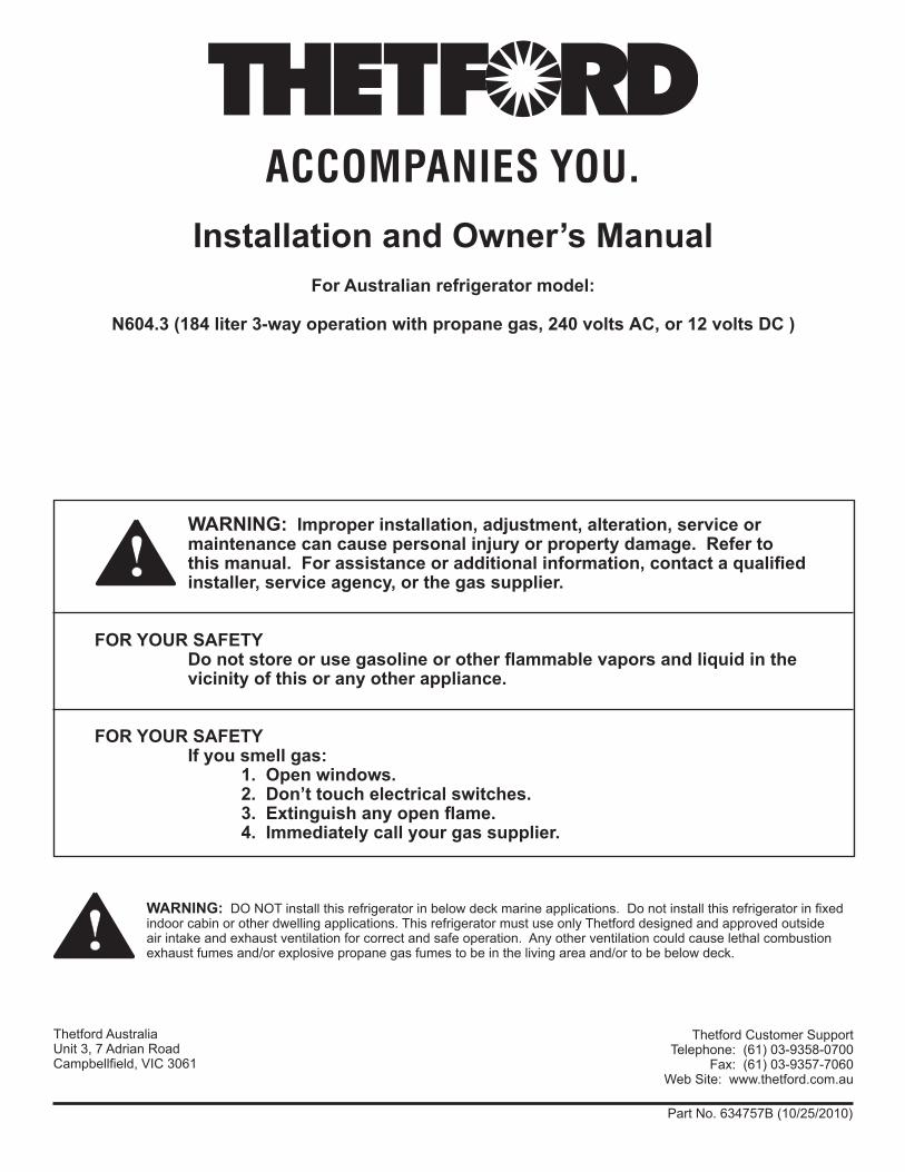
Thetford Customer Support Telephone: (61) 03-9358-0700 Fax: (61) 03-9357-7060 Web Site: www.thetford.com.au WARNING: Improper installation, adjustment, alteration, service or maintenance can cause personal injury or property damage. Refer to this manual. For assistance or additional information, contact a qualified installer, service agency, or the gas supplier. FOR YOUR SAFETY Do not store or use gasoline or other flammable vapors and liquid in the vicinity of this or any other appliance. FOR YOUR SAFETY If you smell gas: 1. Open windows. 2. Don’t touch electrical switches. 3. Extinguish any open flame. 4. Immediately call your gas supplier. Part No. 634757B (10/25/2010) Installation and Owner’s Manual For Australian refrigerator model: N604.3 (184 liter 3-way operation with propane gas, 240 volts AC, or 12 volts DC ) WARNING: DO NOT install this refrigerator in below deck marine applications. Do not install this refrigerator in fixed indoor cabin or other dwelling applications. This refrigerator must use only Thetford designed and approved outside air intake and exhaust ventilation for correct and safe operation. Any other ventilation could cause lethal combustion exhaust fumes and/or explosive propane gas fumes to be in the living area and/or to be below deck. Thetford Australia Unit 3, 7 Adrian Road Campbellfield, VIC 3061 ! !
-
Upload
nguyendiep -
Category
Documents
-
view
217 -
download
2
Transcript of Installation and Owner’s Manual - RV Parts Express (61) 03-9357-7060 Web Site: www ... sizes as...
Thetford Customer Support Telephone: (61) 03-9358-0700
Fax: (61) 03-9357-7060Web Site: www.thetford.com.au
WARNING: Improper installation, adjustment, alteration, service or maintenance can cause personal injury or property damage. Refer to this manual. For assistance or additional information, contact a qualified installer, service agency, or the gas supplier.
FOR YOUR SAFETY Do not store or use gasoline or other flammable vapors and liquid in the vicinity of this or any other appliance.
FOR YOUR SAFETYIf you smell gas:
1. Open windows.2. Don’t touch electrical switches.3. Extinguish any open flame.4. Immediately call your gas supplier.
Part No. 634757B (10/25/2010)
Installation and Owner’s ManualFor Australian refrigerator model:
N604.3 (184 liter 3-way operation with propane gas, 240 volts AC, or 12 volts DC )
WARNING: DO NOT install this refrigerator in below deck marine applications. Do not install this refrigerator in fixed indoor cabin or other dwelling applications. This refrigerator must use only Thetford designed and approved outside air intake and exhaust ventilation for correct and safe operation. Any other ventilation could cause lethal combustion exhaust fumes and/or explosive propane gas fumes to be in the living area and/or to be below deck.
Thetford AustraliaUnit 3, 7 Adrian RoadCampbellfield, VIC 3061
!
!

Installation / Owner’s Manual 2
Table of Contents
For defined warranty terms, please see the one page warranty statement included in the product information packet.
Owners manual
Safety Awareness .................................................................................................................................................................................3Safety Instructions ................................................................................................................................................................................3About Your Refrigerator ........................................................................................................................................................................4 Storage volume .............................................................................................................................................................................4 Leveling .........................................................................................................................................................................................4 Operation during travel ..................................................................................................................................................................4 Food compartment ........................................................................................................................................................................4 Crispers .........................................................................................................................................................................................4 Door bins .......................................................................................................................................................................................4 Adjustable shelves ........................................................................................................................................................................5 Freezer compartment ....................................................................................................................................................................5 Door handles .................................................................................................................................................................................5 Temperature switch monitor ..........................................................................................................................................................5Operating the Refrigerator Controls .....................................................................................................................................................5 Control Panel.................................................................................................................................................................................5 Ignition - propane gas operation....................................................................................................................................................6 Do a test of the gas safety valve ...................................................................................................................................................6 Start up - AC operation ..................................................................................................................................................................7 Start up - DC operation .................................................................................................................................................................7 Shut down .....................................................................................................................................................................................7 DC Operation Precautions ............................................................................................................................................................7 DC Operation Guidelines ..............................................................................................................................................................7Effects of High Altitude on Propane Gas Operation .............................................................................................................................7Refrigerator Care Checklist ..................................................................................................................................................................8Defrosting .............................................................................................................................................................................................8Cleaning ...............................................................................................................................................................................................9 Drip tray .........................................................................................................................................................................................9Door Sealing .........................................................................................................................................................................................9Refrigerator Maintenance Checklist ...................................................................................................................................................10Refrigerator Storage ...........................................................................................................................................................................10Refrigerator Maintenance ................................................................................................................................................................... 11 Gas flame appearance ................................................................................................................................................................ 11 Remove and clean the burner orifice .......................................................................................................................................... 11Remove the Refrigerator ....................................................................................................................................................................12Reinstall the Refrigerator ....................................................................................................................................................................13Replacement Parts .............................................................................................................................................................................13Wiring Pictorial....................................................................................................................................................................................14Wiring Diagram ...................................................................................................................................................................................15
Installation Manual
Safety Awareness ...............................................................................................................................................................................16Safety Instructions ..............................................................................................................................................................................16Certification and Code Requirements.................................................................................................................................................17Ventilation Requirements....................................................................................................................................................................17Key Refrigerator Dimensions..............................................................................................................................................................18Assemble the Enclosure .....................................................................................................................................................................18Install the Upper and Lower Vents......................................................................................................................................................19Install Decorative Door Panels ...........................................................................................................................................................23Install the Refrigerator ........................................................................................................................................................................23Reverse the door swing ......................................................................................................................................................................24Connect the Electrical Components ...................................................................................................................................................26 Connect the 240 volt AC supply ..................................................................................................................................................26 Connect the 12 volt DC supply ....................................................................................................................................................26Connect the Propane Gas Components.............................................................................................................................................27 Connect the propane gas supply system ....................................................................................................................................27 Examine the gas supply system for leaks ...................................................................................................................................27Troubleshooting Refrigerator Problems ..............................................................................................................................................28
Installation /Owner’s Manual 3
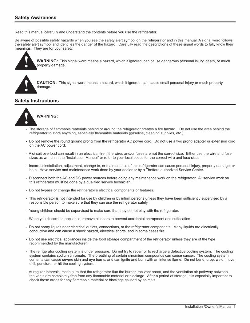
WARNING:
- The storage of flammable materials behind or around the refrigerator creates a fire hazard. Do not use the area behind the refrigerator to store anything, especially flammable materials (gasoline, cleaning supplies, etc.)
- Do not remove the round ground prong from the refrigerator AC power cord. Do not use a two prong adapter or extension cord on the AC power cord.
- A circuit overload can result in an electrical fire if the wires and/or fuses are not the correct size. Either use the wire and fuse sizes as written in the “Installation Manual” or refer to your local codes for the correct wire and fuse sizes.
- Incorrect installation, adjustment, change to, or maintenance of this refrigerator can cause personal injury, property damage, or both. Have service and maintenance work done by your dealer or by a Thetford authorized Service Center.
- Disconnect both the AC and DC power sources before doing any maintenance work on the refrigerator. All service work on this refrigerator must be done by a qualified service technician.
- Do not bypass or change the refrigerator’s electrical components or features.
- This refrigerator is not intended for use by children or by infirm persons unless they have been sufficiently supervised by a responsible person to make sure that they can use the refrigerator safely.
- Young children should be supervised to make sure that they do not play with the refrigerator.
- When you discard an appliance, remove all doors to prevent accidental entrapment and suffocation.
- Do not spray liquids near electrical outlets, connections, or the refrigerator components. Many liquids are electrically conductive and can cause a shock hazard, electrical shorts, and in some cases fire.
- Do not use electrical appliances inside the food storage compartment of the refrigerator unless they are of the type recommended by the manufacturer.
- The refrigerator cooling system is under pressure. Do not try to repair or to recharge a defective cooling system. The cooling system contains sodium chromate. The breathing of certain chromium compounds can cause cancer. The cooling system contents can cause severe skin and eye burns, and can ignite and burn with an intense flame. Do not bend, drop, weld, move, drill, puncture, or hit the cooling system.
- At regular intervals, make sure that the refrigerator flue the burner, the vent areas, and the ventilation air pathway between the vents are completely free from any flammable material or blockage. After a period of storage, it is especially important to check these areas for any flammable material or blockage caused by animals.
Safety Instructions
Read this manual carefully and understand the contents before you use the refrigerator.
Be aware of possible safety hazards when you see the safety alert symbol on the refrigerator and in this manual. A signal word follows the safety alert symbol and identifies the danger of the hazard. Carefully read the descriptions of these signal words to fully know their meanings. They are for your safety.
WARNING: This signal word means a hazard, which if ignored, can cause dangerous personal injury, death, or much property damage.
CAUTION: This signal word means a hazard, which if ignored, can cause small personal injury or much property damage.
Safety Awareness
!
!
!
Installation / Owner’s Manual 4
About Your Refrigerator
CAUTION:
- The rear of the refrigerator has sharp edges and corners. To prevent cuts or abrasions when working on the refrigerator, be careful and wear cut resistant gloves.
Storage Volume:
This refrigerator is made to store fresh and frozen foods and for making ice. Gross capacity 184 Liter
Leveling:
CAUTION: The refrigerator is made to operate within 3° off level side-to-side and 6° off level front-to-back (as looking at the front of the refrigerator). Operating it at more than these limits can cause damage to the cooling system and create a risk of personal injury or property damage. Make sure the vehicle is level before you operate the refrigerator.
Operation during travel:
While the refrigerator should be level when the vehicle is stopped, performance during travel is not usually effected. Do not operate the refrigerator on propane gas while travelling. This can reduce performance, cause an unstable flame, or extinguish the flame.
Food compartment:
Ignite or start up the refrigerator and let it cool for eight hours before loading with food. If the refrigerator does not start to cool down after about two hours, contact your dealer or an authorized Thetford Service Center.
For the best cooling performance:
- Let air move freely inside the entire food compartment.
- Do not cover the shelves with plastic, paper, etc.
To decrease the amount of ice that collects on the cooling fins:
- Cover all liquids and moist foods.
- Let all hot foods cool before putting them in the refrigerator.
- Do not open the door any longer than necessary.
Crisper(s):
The crisper(s) are located at the bottom of the fresh food compartment and supply a storage area to preserve fruit and vegetable freshness. Make sure that you always push the crispers fully in.
NOTE: Do not wash the crispers in a dishwasher. The crispers are not dishwasher safe.
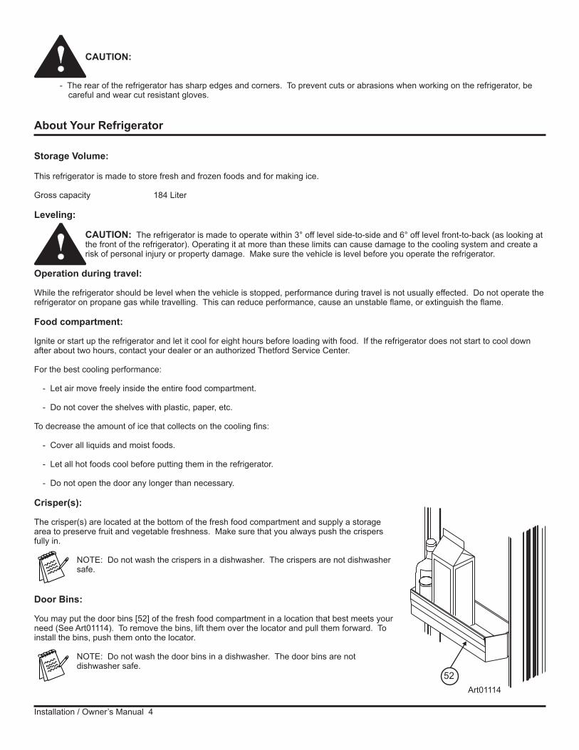
Door Bins:
You may put the door bins [52] of the fresh food compartment in a location that best meets your need (See Art01114). To remove the bins, lift them over the locator and pull them forward. To install the bins, push them onto the locator.
NOTE: Do not wash the door bins in a dishwasher. The door bins are not dishwasher safe.
!
!
Art01114
52
Installation /Owner’s Manual 5
Adjustable shelves:
The shelves in the freezer and the fresh food compartment are made so you can remove them or move them.
To remove or move the shelf of the freezer:
- Pull the shelf forward out of the slot.
- Push it fully into the slot that you wish.
To remove or move each shelf of the fresh food compartment:
- Remove the screw from the retainer of each shelf at the rear of the refrigerator.
- Pull each shelf forward out of the slot.
- Push each shelf fully into the slot that you wish.
- Attach the retainer with the screw.
Freezer compartment:
The freezer compartment is made to keep pre-frozen food frozen and not to quick freeze food. Keep pre-frozen foods in the freezer compartment.
NOTE: Do not put other items on the ice tray while the water is freezing. The water freezes more rapidly if the thermostat is at the coldest temperature setting.
Door handles:
During travel, the door latch prevents the door from opening. When closing each door, push the door toward the refrigerator until you hear a “click” sound.
To open each door, pull the handle away from the refrigerator.
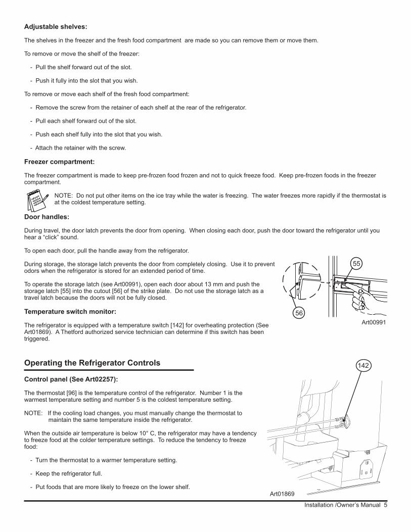
During storage, the storage latch prevents the door from completely closing. Use it to prevent odors when the refrigerator is stored for an extended period of time.
To operate the storage latch (see Art00991), open each door about 13 mm and push the storage latch [55] into the cutout [56] of the strike plate. Do not use the storage latch as a travel latch because the doors will not be fully closed.
Temperature switch monitor:
The refrigerator is equipped with a temperature switch [142] for overheating protection (See Art01869). A Thetford authorized service technician can determine if this switch has been triggered.
Art01869
142
Art00991
55
56
Operating the Refrigerator Controls
Control panel (See Art02257):
The thermostat [96] is the temperature control of the refrigerator. Number 1 is the warmest temperature setting and number 5 is the coldest temperature setting.
NOTE: If the cooling load changes, you must manually change the thermostat to maintain the same temperature inside the refrigerator.
When the outside air temperature is below 10° C, the refrigerator may have a tendency to freeze food at the colder temperature settings. To reduce the tendency to freeze food:
- Turn the thermostat to a warmer temperature setting.
- Keep the refrigerator full.
- Put foods that are more likely to freeze on the lower shelf.
Installation / Owner’s Manual 6
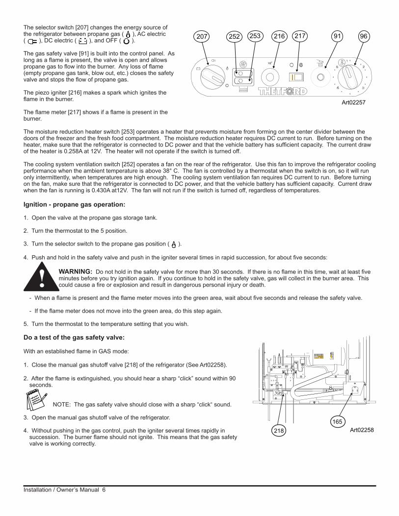
The selector switch [207] changes the energy source of the refrigerator between propane gas ( ), AC electric ( ), DC electric ( ), and OFF ( ).
The gas safety valve [91] is built into the control panel. As long as a flame is present, the valve is open and allows propane gas to flow into the burner. Any loss of flame (empty propane gas tank, blow out, etc.) closes the safety valve and stops the flow of propane gas.
The piezo igniter [216] makes a spark which ignites the flame in the burner.
The flame meter [217] shows if a flame is present in the burner.
The moisture reduction heater switch [253] operates a heater that prevents moisture from forming on the center divider between the doors of the freezer and the fresh food compartment. The moisture reduction heater requires DC current to run. Before turning on the heater, make sure that the refrigerator is connected to DC power and that the vehicle battery has sufficient capacity. The current draw of the heater is 0.258A at 12V. The heater will not operate if the switch is turned off.
The cooling system ventilation switch [252] operates a fan on the rear of the refrigerator. Use this fan to improve the refrigerator cooling performance when the ambient temperature is above 38° C. The fan is controlled by a thermostat when the switch is on, so it will run only intermittently, when temperatures are high enough. The cooling system ventilation fan requires DC current to run. Before turning on the fan, make sure that the refrigerator is connected to DC power, and that the vehicle battery has sufficient capacity. Current draw when the fan is running is 0.430A at12V. The fan will not run if the switch is turned off, regardless of temperatures.
Ignition - propane gas operation:
1. Open the valve at the propane gas storage tank.
2. Turn the thermostat to the 5 position.
3. Turn the selector switch to the propane gas position ( ).
4. Push and hold in the safety valve and push in the igniter several times in rapid succession, for about five seconds:
WARNING: Do not hold in the safety valve for more than 30 seconds. If there is no flame in this time, wait at least five minutes before you try ignition again. If you continue to hold in the safety valve, gas will collect in the burner area. This could cause a fire or explosion and result in dangerous personal injury or death.
- When a flame is present and the flame meter moves into the green area, wait about five seconds and release the safety valve.
- If the flame meter does not move into the green area, do this step again.
5. Turn the thermostat to the temperature setting that you wish.
Do a test of the gas safety valve:
With an established flame in GAS mode:
1. Close the manual gas shutoff valve [218] of the refrigerator (See Art02258).
2. After the flame is extinguished, you should hear a sharp “click” sound within 90 seconds.
NOTE: The gas safety valve should close with a sharp “click“ sound.
3. Open the manual gas shutoff valve of the refrigerator.
4. Without pushing in the gas control, push the igniter several times rapidly in succession. The burner flame should not ignite. This means that the gas safety valve is working correctly.
!
207 91 96253252 216 217
Art02257
Art02258218165

Installation /Owner’s Manual 7
Start up - AC operation:
- Make sure that 240 volts AC is available.
- Turn the selector switch to the AC position ( ).
- Turn the thermostat to the temperature setting (numbers 2 -5) that you wish.
NOTE: In AC operation only, the number 1 setting of the thermostat turns the refrigerator off.
Start up - DC operation:
- Make sure that 12 volts DC is available.
- Turn the selector switch to the DC position ( ).
Shut down:
- Turn the selector switch to the OFF position ( ).
DC operation precautions:
This refrigerator is made to operate on DC power while your vehicle is “in transit” and AC power or propane gas sources are not available. Operate the refrigerator on DC power only when the vehicle engine is running.
For the refrigerator to operate correctly on DC power, the battery must be maintained in a fully charged condition.
For the battery to be fully charged at all times during refrigerator operation on DC, the vehicle engine must be running and the battery charging system must be in good operating condition.
Keep in mind the following electrical precautions for DC operation of the refrigerator:
- Good battery condition is necessary for correct DC operation.
- The capacity of the battery charging system must be more than what is necessary for the refrigerator and other DC appliances.
- While the vehicle engine is running, make sure the voltage of the DC power supply leads at the refrigerator is more than 11.5VDC.
DC operation guidelines:
DC operation is intended only to maintain the temperature of the refrigerator and its contents when they are already cool.
The DC operation is not intended for the initial start up and cooling of the refrigerator. Always use either the AC operation or propane gas operation to initially start up and cool the refrigerator. The refrigerator must be cooled and the temperature must be steady before you operate the refrigerator on DC.
Keep in mind the following guidelines for DC operation of the refrigerator:
- Use DC operation of the refrigerator while the vehicle is in transit.
- Do not use DC operation until the refrigerator and its contents are completely cooled.
- Only use DC operation if the vehicle battery and battery charging system are in good operating condition.
Effects of High Altitude on Propane Gas Operation
When you operate the refrigerator on propane gas at altitudes higher than 1.7 km above sea level:
- You may experience reduced cooling performance of the refrigerator.
- You may experience burner outages.
To avoid these possible problems, Thetford recommends that you operate the refrigerator on AC when at altitudes higher than 1.7km above sea level.

Installation / Owner’s Manual 8
Refrigerator Care Checklist
Your refrigerator will give you years of trouble free service if you do these simple checks every three to six months:
- Keep the food compartment and the freezer clean. See “Cleaning”.
- Defrost the refrigerator as necessary. See “Defrosting”.
- Make sure the door seals correctly. See “Door Sealing“.
- Be aware of any cooling changes that are not because of weather, loading, or gas control changes. If changes occur, contact your dealer or an authorized Thetford Service Center.
- Make sure the gas supply is propane gas only and not butane or a butane mixture.
- When in propane gas operation, examine the appearance of the flame. See “Gas Flame Appearance”.
- Make sure the air flow in the lower intake vent, through the refrigerator condenser and coils and out the upper exhaust vent is not blocked or decreased.
- Make sure the area behind the refrigerator is clear. Do not use the area behind the refrigerator for storage of any materials or combustible materials, especially gasoline and other flammable vapors and liquids.
Defrosting
The cooling fins of the refrigerator operate at below freezing temperature and will naturally form frost from humidity, which is always present in the air. The humidity inside the refrigerator increases:
- with higher outside temperature and humidity.
- with the storage of non-sealed fresh foods or warm foods.
- with the amount of time that the door(s) are open.
- with any air leakage into the refrigerator.
It is normal for frost to collect inside the freezer. Excess frost decreases the cooling performance of the refrigerator. Defrost the refrigerator and freezer as necessary:
- Remove all food from the refrigerator.
- Turn the refrigerator OFF.
NOTE: Defrosting the refrigerator makes excess water inside the refrigerator.
- Remove the drain hose from the drip cup at the rear of the refrigerator.
- Put the drain hose into a two liter or larger container to capture water.
- Put dry towels (etc.) inside the refrigerator and freezer to absorb melted frost.
CAUTION: High temperatures can cause the inside surfaces of the refrigerator to warp or melt. Do not use pans of HOT water, a hair dryer, or any other high temperature devices to defrost the refrigerator. Do not use any hard or sharp objects to remove frost. Damage to the interior of the refrigerator can occur.
- To increase the speed of defrosting, put pans of WARM water in the refrigerator and freezer.
- Remove the wet towels (etc.) and dry the interior.
- Remove the drain hose from the large container and put the drain hose back into the drip cup.
!

Installation /Owner’s Manual 9
A good time to clean the refrigerator is just after you defrost it.
Clean the inside of the refrigerator as often as necessary to avoid food odors:
- Remove all food from the refrigerator.
NOTE: Do not use abrasive cleaners, chemicals, or scouring pads because they can damage the interior of the refrigerator.
- Wash the interior with a solution of liquid dish detergent and warm water.
- Rinse with a solution of baking soda and clean water.
- Dry with a clean cloth.
- Put all food in the refrigerator.
Drip tray:
To remove and clean the drip tray:
- Pull the shelf forward to remove from the refrigerator
- Make sure that the drip tray is empty of water.
- Pull the drip tray out of the drain hose.
- Pull the drip tray forward to remove from the slots in the refrigerator cabinet.
- Clean the drip tray.
- Push the drip tray back into the slots in the refrigerator cabinet.
- Push the drip tray back into the drain hose.
- Put the wire shelf back in the original position.
Cleaning
- Remove the large container from the enclosure.
- Start up the refrigerator.
- Allow the refrigerator to cool down.
- Return all food to the refrigerator.
Door Sealing
Check the seal of the doors.
If either door does not seal correctly, excess frost will collect inside the refrigerator. Make sure the doors seal correctly (See Art00980):
- Close each door on a piece of paper that is about the size and thickness of a dollar bill.
- Gently pull the paper.
- You should feel a slight drag between the gasket and the cabinet.
- Do this on all four sides of the door.
- If you do not feel a slight drag on thepaper, the door does not seal correctly.
- Have your dealer or an authorized Thetford Service Center correct the seal of the door. Art00980

Installation / Owner’s Manual 10
Refrigerator Maintenance Checklist
Read and understand the following maintenance sections of this manual.
NOTE: Thetford is not responsible for installation, adjustment, alteration, service, or maintenance performed by anyone other than a qualified RV dealer or an authorized Thetford Service Center.
Have a qualified RV dealer or an authorized Thetford Service Center do these annual safety and maintenance checks:
- Examine the gas supply lines for leaks.
- Replace or repair if necessary.
- Make sure the propane gas pressure is 2.7kPa.
- Adjust if necessary.
- Make sure the combustion seal is complete and intact.
- Replace or repair it if necessary.
- Make sure the burner and the burner orifice are clean (See Art00956).
- Clean if necessary.
- Make sure the electrode spark gap [167] is 3-5mm (See Art00955).
- Adjust if necessary.
- Make sure the AC voltage is 216 - 264VAC and the DC voltage is 11.7 - 15.4VDC.
- Make sure the thermocouple tip is clean and secure.
- Make sure the area at the rear of the refrigerator is free of any combustible materials, gasoline, and other flammable vapors and liquids.
Refrigerator Storage
Before the refrigerator is stored for an extended (seasonal) period of time:
- Defrost and clean the interior of the refrigerator.
- Close the doors with the storage latch.
If the refrigerator is stored for an extended period of time, before start up:
- Make sure there are no obstructions in the vents, the ventilation air pathway, the burner, the orifice, or the flue area.
7576
Art00955
167
Art 00956
77 787980
Installation /Owner’s Manual 11
Refrigerator Maintenance
Gas flame appearance:
While in propane gas operation, examine the appearance of the gas flame:
- Turn the thermostat to the 5 position.
- Open the lower intake vent.
CAUTION: The burner box cover can be hot. Wear gloves to avoid burns.
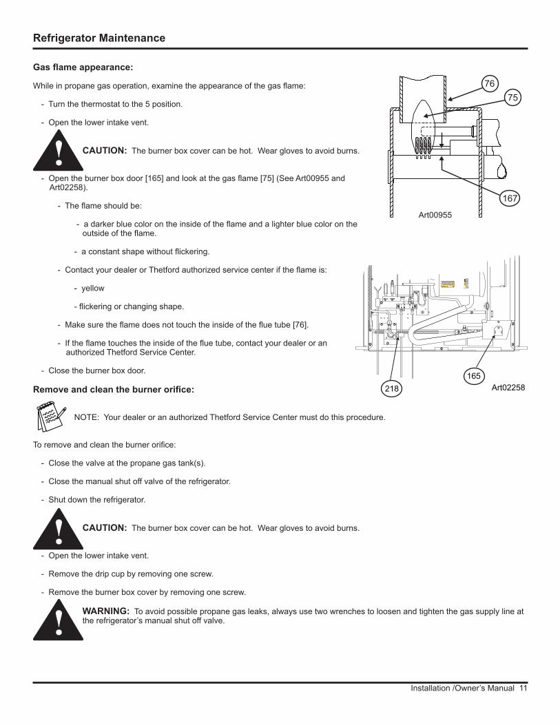
- Open the burner box door [165] and look at the gas flame [75] (See Art00955 and Art02258).
- The flame should be:
- a darker blue color on the inside of the flame and a lighter blue color on the outside of the flame.
- a constant shape without flickering.
- Contact your dealer or Thetford authorized service center if the flame is:
- yellow
- flickering or changing shape.
- Make sure the flame does not touch the inside of the flue tube [76].
- If the flame touches the inside of the flue tube, contact your dealer or an authorized Thetford Service Center.
- Close the burner box door.
Remove and clean the burner orifice:
NOTE: Your dealer or an authorized Thetford Service Center must do this procedure.
To remove and clean the burner orifice:
- Close the valve at the propane gas tank(s).
- Close the manual shut off valve of the refrigerator.
- Shut down the refrigerator.
CAUTION: The burner box cover can be hot. Wear gloves to avoid burns.
- Open the lower intake vent.
- Remove the drip cup by removing one screw.
- Remove the burner box cover by removing one screw.
WARNING: To avoid possible propane gas leaks, always use two wrenches to loosen and tighten the gas supply line at the refrigerator’s manual shut off valve.
!
!
!
Art02258218165
7576
Art00955
167

Installation / Owner’s Manual 12
- Remove the flare nut from the orifice assembly [77] (See Art00956).
- Remove the orifice assembly from the burner [78].
WARNING: Do not try to remove the orifice [79] from the orifice adapter [80] when cleaning. Removal will damage the orifice and seal of the orifice and can cause a propane gas leak. Leaking propane gas can ignite or explode which can result in dangerous personal injury or death. Do not clean the orifice with a pin or other objects.
- Clean the orifice assembly with air pressure and alcohol only.
- Using a wrench, assemble the orifice assembly to the burner.
- Assemble the flare nut to the orifice assembly.
- Tighten the flare nut by hand.
- Hold the orifice assembly securely and, using a wrench, tighten the flare nut 1/4 revolution only.
- Examine all of the connections for gas leaks.
- Clean the burner box.
- Assemble the burner box cover.
- Assemble the drip cup.
!
Remove the Refrigerator
NOTE: Your dealer or an authorized Thetford Service Center must do this procedure.
CAUTION: The rear of the refrigerator has sharp edges and corners. To prevent cuts or abrasions when working on the refrigerator, be careful and wear cut resistant gloves.
1. Close the valve at the propane gas tank(s).
WARNING: To avoid possible propane gas leaks, always use two wrenches to loosen and tighten the gas supply line at the refrigerator’s manual shut off valve.
2. Open the lower intake vent and remove the gas supply line from the manual shut off valve of the refrigerator.
3. Remove the AC power cord from the power point.
4. Remove the DC wiring from the refrigerator:
- Remove the DC wiring from the battery or the converter of the vehicle.
- Put a mark on the DC wires so you can put them back in the correct location.
- Remove the DC wires from the refrigerator.
5. Remove the screws from the mounting flange at the rear of the refrigerator.
6. Remove the top trim by gasping firmly and pulling to disengage the metal mounting clips.
7. Remove the screws from the upper and lower mounting flanges on the front of the refrigerator.
8. Remove the refrigerator from the opening.
!
!
Art 00956
77 787980

Installation /Owner’s Manual 13
NOTE: Your dealer or an authorized Thetford Service Center must do this procedure.
WARNING: Make sure the combustion seal [29] is not broken, is completely around the refrigerator mounting flanges, and is between the mounting flanges and the wall of the enclosure (See Art02259). If the combustion seal is not complete, exhaust fumes can be present in the living area of the vehicle. The breathing of exhaust fumes can cause dizziness, nausea, and in extreme cases, death.
1. Push the refrigerator completely into the enclosure.
2. Put the screws though the upper and lower mounting flanges at the front of the refrigerator.
CAUTION: The rear of the refrigerator has sharp edges and corners. To prevent cuts or abrasions when working on the refrigerator, be careful and wear cut resistant gloves.
4. Open the lower intake vent and put the screws through the mounting flange at the rear of the refrigerator and into the floor.
WARNING: To avoid possible propane gas leaks, always use two wrenches to loosen and tighten the gas supply line at the refrigerator’s manual shut off valve.
5. Attach the gas supply line to the manual shut off valve of the refrigerator.
6. Open the valve at the propane gas tank(s).
WARNING: Do not allow the leak checking solution to touch the electrical components. Many liquids are electrically conductive and can cause a shock hazard,electrical shorts, and in some cases fire.
7. Examine the gas supply line for leaks.
8. Connect the DC wiring to the refrigerator:
- Install the DC fuse or connect the DC wiring to the battery or the converter.
- Connect the DC wires from the refrigerator.
9. Connect the AC power cord to the receptacle.
Reinstall the Refrigerator
!
!
!
!
Replacement Parts
You may purchase replacement parts through your local RV dealer or an authorized Thetford Service Center.
29
28
Art02259
40

Installation / Owner’s Manual 14
Wiring Pictorial
GND
High TempLimit Switch
F
F
Fan T-Stat
B1
B2
B3
B4
B5
B6
B7
B8
C1
C2
C3
C4
C5
C6
C7
C8
1a
1b
3a
3b
2b
2a
4b
4a
White/Red
White/Red
Brown
Brown
Blue
Blue
White
White
White/Black
White/Black
Black
Black
Red
Red
Black
Black
White/VioletWhite/Violet
Red/White
Red
/Wh
ite
Red
Red
Wh
ite/
Bla
ck
Bro
wn
Blu
e
Black
White/Violet
Red
Wh
ite/
Red
Red
Green
Green
Green
Gre
en
OrangeOrange
Ora
ng
e
Orange
Green
Red
Top of Refrigerator
AC Heater 3A
DC AUX 3A
12V GND +12V
85
86
30
87
30ADC HTR 30A
Fan
MFBlack
Red/White Red
Black
Bro
wn
Bro
wn
White/Red
Wh
ite/
Bla
ck
Red
Red Red
+12Vdc
RED
BLA
CK
White
/Black
M F
Blue
BlueM F
Black
DC HEATER
AC HEATER
Blue
White/Violet
Yello
w/G
reen
Yello
w/G
reen
Red
Red
Blue
Blu
e
FLAMEMETER
Back of Refrigerator
2 3 4
5 6 8
Yellow/Green
Yellow/Green
Yello
w/G
reen Blac
k
Red
634257 Rev B (10-25-2010)
Red
White
White/Black
Divider Heater
Dashed line = Foamed In
ACPower Cord
Fan Switch
Divider Heater Switch
1
7
1A
4B5B
2A
6B
3A
Whi
te
Installation /Owner’s Manual 15
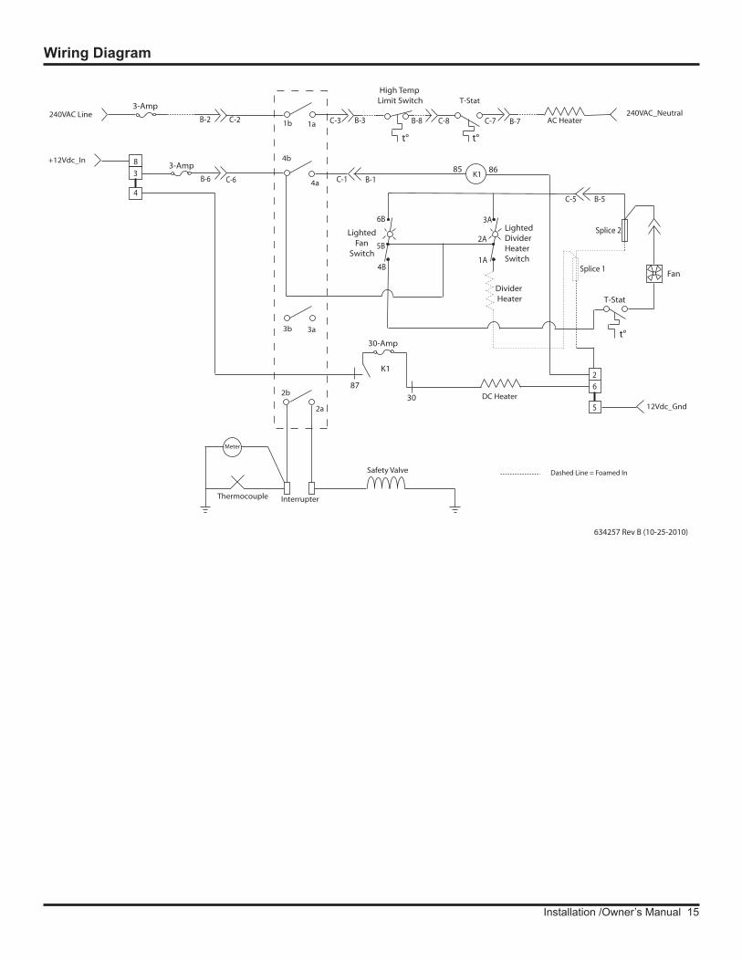
Wiring Diagram
240VAC Line AC Heater
DC Heater
K1
12Vdc_Gnd
240VAC_Neutral
Safety Valve
Thermocouple Interrupter
4a
4b
1a1b
2a
2b
T-Stat
Meter
3-Amp
High TempLimit Switch
30-Amp
85 86
Lighted Fan Switch
LightedDividerHeaterSwitch
Divider Heater T-Stat
3-Amp
K1
30
87
Fan
3a3bt°
t° t°
C-2B-2 C-3 B-3 B-8 C-8 C-7 B-7
C-6B-6 C-1 B-1
5
26
+12Vdc_In 8
3
4C-5 B-5
2A
1A
3A
5B
4B
6BSplice 2
Splice 1
634257 Rev B (10-25-2010)
Dashed Line = Foamed In
Installation / Owner’s Manual 16
Safety Instructions
Safety Awareness
Read this manual carefully and understand the contents before you install the refrigerator.
Be aware of possible safety hazards when you see the safety alert symbol on the refrigerator and in this manual. A signal word follows the safety alert symbol and identifies the danger of the hazard. Carefully read the descriptions of these signal words to fully know their meanings. They are for your safety.
WARNING: This signal word means a hazard, which if ignored, can cause dangerous personal injury, death, or much property damage.
CAUTION: This signal word means a hazard, which if ignored, can cause small personal injury or much property damage.
WARNING:
- This refrigerator is made for use in RV and towable applications, and is correct for camping use. It is made to operate with, and be connected to, multiple energy sources. Disconnect all energy sources before you remove the refrigerator or do servicing to the refrigerator.
- This refrigerator is not approved for use as a free standing refrigerator. It is equipped for the use of propane gas only and can not be changed to use any other fuels (natural gas, butane, etc.).
- Incorrect installation, adjustment, alteration, or maintenance of this refrigerator can cause personal injury, property damage, or both.
- Obey the instructions in this manual to install the intake and exhaust vents.
- Do not install the refrigerator directly on carpet. Put the refrigerator on a metal or wood panel that extends the full width and depth of the refrigerator.
- Do not allow anything to touch the refrigerator cooling system.
- Propane gas can ignite and cause an explosion that can result in property damage, personal injury, or death. Do not smoke or create sparks. Do not use an open flame to examine the propane gas supply line for leaks. Always use two wrenches to tighten or loosen the propane gas supply line connections.
- Make sure the electrical installation obeys all applicable codes. See “Certification and Code Requirements” section.
- Do not bypass or change the refrigerator’s electrical components or features.
- Do not spray liquids near electrical outlets, connections, or the refrigerator components. Many liquids are electrically conductive and can cause a shock hazard, electrical shorts, and in some cases fire.
- The refrigerator cooling system is under pressure. Do not try to repair or to recharge a defective cooling system.
- The cooling system contains sodium chromate. The breathing of certain chromium compounds can cause cancer. The cooling system contents can cause severe skin and eye burns, and can ignite and burn with an intense flame. Do not bend, drop, weld, move, drill, puncture, or hit the cooling system.
CAUTION:
- The rear of the refrigerator has sharp edges and corners. To prevent cuts or abrasions when working on the refrigerator, use caution and wear cut resistant gloves.
Installation Manual
!!
!
!
Installation /Owner’s Manual 17
Ventilation Requirements
WARNING: The completed installation must:
- Make sure there is sufficient intake of fresh air for combustion.
- Make sure the living space is completely isolated from the combustion system of the refrigerator.
- Make sure there is complete and unrestricted ventilation of the flue exhaust which, in gas mode, can produce carbon monoxide. The breathing of carbon monoxide fumes can cause dizziness, nausea, or in extreme cases, death.
- Make sure the refrigerator is completely isolated from its heat generating components through the correct use of baffles and panel construction.
Certified installation needs one lower intake vent and one upper exhaust vent. Install the upper exhaust vent either through the roof or through the side wall of the vehicle exactly as written in this manual. Any other installation method voids both the certification and the factory warranty of the refrigerator.
The bottom of the opening for the lower intake vent, which is also the service access door, must be even with or immediately below the floor level. This allows any leaking propane gas to escape to the outside and not to collect at floor level.
While there are no maximum clearances specified for certification, the following maximum clearances are necessary for correct refrigeration:
Bottom 0mm min. 0mm max.
Each Side 0mm min 3mm max.
Top 0mm min. 6mm max.
Rear 0mm min. 25mm max.
These clearances plus the lower and upper vents cause the natural air draft that is necessary for good refrigeration. Cooler air comes in through the lower intake vent, goes up around the refrigerator coils where it removes the excess heat from the refrigerator components, and goes out through the upper exhaust vent. If this air flow is blocked or decreased, the refrigerator will not cool correctly.
!
Certification and Code Requirements
This refrigerator is certified under the latest edition of the Australian Gas Association Standard AS4555/AG105 and the Australian National Electric Standard for household and similar electrical appliances AS/NZS 3350.1:1994.
The refrigerator is made for installation in a caravan or a recreational vehicle. The installation must obey the requirements of this “installation Manual” for the THETFORD limited warranty to be in effect.
The installation must agree with local codes. In the absence of local codes, the installation must obey these standards:
- Gas Installations AS5601.
- National Fuel Gas Code, ANSI Z223.1 (latest edition).
- Manufactured Home Construction and Safety Standard, Title 24 CFR, Part 3280.
- Standard for Recreational Vehicles, RVIA A119.2 latest edition.
- All gas supply piping and fittings must obey local, and national codes about type and size.

Installation / Owner’s Manual 18
Assemble the Enclosure
1. Make sure the enclosure is: 1415 mm high x 607 mm wide x 620 mm deep.
2. Make sure the floor is solid and level.
- The floor must be metal or a wood panel and extend the full width and depth of the enclosure.
- The floor must be able to support the weight of the refrigerator and its contents.
3. Make sure there are no adjacent heat sources such as a furnace vent, a hot water heater vent, etc.
4. If there is more than 13mm between either side of the refrigerator and the inside of the enclosure:
- Fill the space with fiberglass insulation or add a baffle to eliminate the excess clearance.
- Make sure that the rear of the batt-type insulation is between 455 - 485 mm from the face of the enclosure.
- Securely attach the batt-type insulation to the enclosure so that it remains in this position during refrigerator installation, if it becomes wet, and in windy conditions.
Key Refrigerator Dimensions
These key refrigerator dimensions are for your reference as necessary (See Art02270).
Refrigerator cabinet width w/o trim - 596.2mm max. ......................................................................................................................... 1 Refrigerator width overall w/ trim - 624.8mm..................................................................................................................................... 2 Refrigerator cabinet to side trim - 20.3mm ........................................................................................................................................ 3 Refrigerator cabinet height w/o trim - 1407mm max. ........................................................................................................................ 4 Refrigerator height overall w/ trim - 1454mm .................................................................................................................................... 5 Refrigerator cabinet to top/bottom trim - 30mm................................................................................................................................. 6 Enclosure wall to hinges - 27.9mm ................................................................................................................................................... 7 Refrigerator cabinet to center of handles - 825.5mm ........................................................................................................................ 8
5
8
4
6
1
2
37
Art02270
Installation /Owner’s Manual 19
!
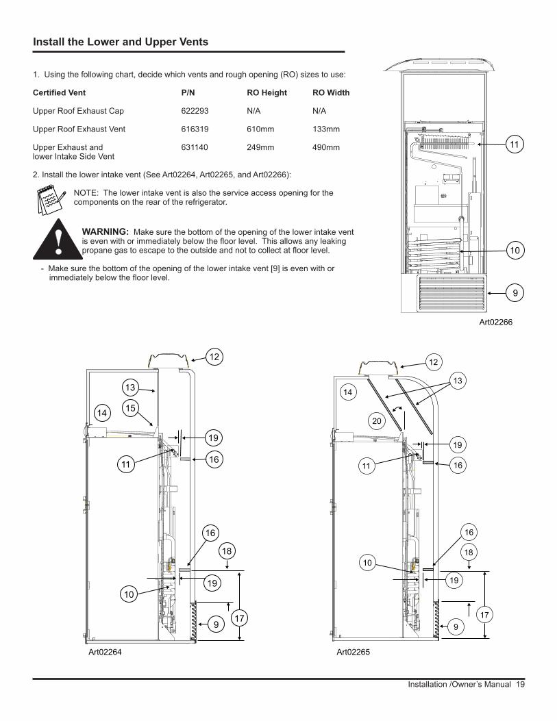
1. Using the following chart, decide which vents and rough opening (RO) sizes to use:
Certified Vent P/N RO Height RO Width
Upper Roof Exhaust Cap 622293 N/A N/A
Upper Roof Exhaust Vent 616319 610mm 133mm
Upper Exhaust and 631140 249mm 490mmlower Intake Side Vent
2. Install the lower intake vent (See Art02264, Art02265, and Art02266):
NOTE: The lower intake vent is also the service access opening for the components on the rear of the refrigerator.
WARNING: Make sure the bottom of the opening of the lower intake vent is even with or immediately below the floor level. This allows any leaking propane gas to escape to the outside and not to collect at floor level.
- Make sure the bottom of the opening of the lower intake vent [9] is even with or immediately below the floor level.
Install the Lower and Upper Vents
1019
17
Art02264
18
9
19
16
11
13
16
12
1514
Art02265
14
12
13
1611
20
19
19
17
1810
9
16
Art02266
9
11
10

Installation / Owner’s Manual 20
!- Align the right edge of the lower intake vent with the right edge of the refrigerator cabinet as viewed from the rear.
3. Install the upper exhaust vent:
CAUTION: Make sure that no sawdust, insulation, or other construction debris is on the refrigerator or in the enclosure. Debris can cause a combustion hazard and prevent the refrigerator from operating correctly.
NOTE: Tighten the screws of the upper roof exhaust cap to 11.5kgf/cm. Also make sure that the air flow around the upper roof exhaust cap is not blocked or decreased by other roof mounted features such as a luggage carrier, an air conditioner, a solar panel, etc.
- If the design of the vehicle allows, install the roof exhaust vent [12] directly above the condenser [11] of the refrigerator (See Art02264).
- Install a baffle [13] to prevent stagnant hot air in the area [14] above the refrigerator.
- Make sure there is less than 6mm clearance [15] between the baffle and the top of the refrigerator.
- Make sure the baffle is the full width of the inside of the enclosure.
- If the design of the vehicle does not allow you to install the roof exhaust vent directly above the condenser [11] of the refrigerator (See Art02265).
- Align the roof exhaust vent [12] above the condenser [11] of the refrigerator and move it inboard as necessary.
- Install two baffles [13] to prevent stagnant hot air in the area [14] above the refrigerator.
- Make sure the baffles are the full width of the inside of the enclosure.
- Make sure that the baffles are no more than 45° from vertical [20].
- Put one baffle between the top rear edge of the refrigerator and the inside edge of the upper exhaust vent opening.
- Put the other baffle between the outside edge of the upper exhaust vent opening and the side wall of the vehicle.
- If the depth of the enclosure is 610mm or more and is less than 635mm, no baffles are necessary at the rear of the enclosure.
- If the depth of the enclosure is 635mm or more and is less than 660mm, add two baffles [16] to the rear of the enclosure (See Art02264 and Art02265).
- Put one baffle 455mm to 470mm above the bottom of the enclosure [17] (205mm to 220mm above the top of the lower intake vent opening REF) [18].
- Put the other baffle at the lowest edge of the condenser [11] of the refrigerator.
- Make sure that the baffles are 25mm or less [19] from the coils [10] and condenser of the refrigerator.
- Make sure that the baffles are the full width of the inside of the enclosure.
Installation /Owner’s Manual 21
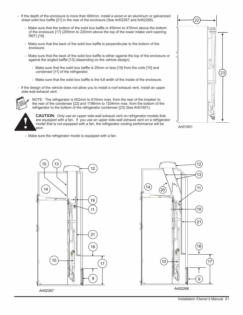
- If the depth of the enclosure is more than 660mm, install a wood or an aluminum or galvanized sheet solid box baffle [21] in the rear of the enclosure (See Art02267 and Art02268).
- Make sure that the bottom of the solid box baffle is 455mm to 470mm above the bottom of the enclosure [17] (205mm to 220mm above the top of the lower intake vent opening REF) [18] .
- Make sure that the back of the solid box baffle is perpendicular to the bottom of the enclosure.
- Make sure that the back of the solid box baffle is either against the top of the enclosure or against the angled baffle [13] (depending on the vehicle design).
- Make sure that the solid box baffle is 25mm or less [19] from the coils [10] and condenser [11] of the refrigerator.
- Make sure that the solid box baffle is the full width of the inside of the enclosure.
- If the design of the vehicle does not allow you to install a roof exhaust vent, install an upper side-wall exhaust vent.
NOTE: The refrigerator is 602mm to 610mm max. from the rear of the breaker to the rear of the condenser [22] and 1196mm to 1204mm max. from the bottom of the refrigerator to the bottom of the refrigerator condenser [23] (See Art01601).
CAUTION: Only use an upper side-wall exhaust vent on refrigerator models that are equipped with a fan. If you use an upper side-wall exhaust vent on a refrigerator model that is not equipped with a fan, the refrigerator cooling performance will be poor.
- Make sure the refrigerator model is equipped with a fan.
22
23
Art01601!
Art02267
21
11
19
1215 13
14
9
1710
18
Art02268
11
18
10 17
9
2014
13
12
21
19

Installation / Owner’s Manual 22
- Install the upper side-wall exhaust vent [24] (See Art02262 and Art02263).
- Make sure the distance [25] from the bottom of the enclosure to the top of the rough opening for the upper exhaust vent is at least 1400mm.
- Align the upper exhaust vent [24] horizontally above the lower intake vent [9] of the refrigerator.
- To prevent stagnant hot air in the area above the refrigerator, install an aluminum or galvanized steel sheet baffle [13] between the top of the refrigerator and the top of the upper exhaust vent.
- Make sure there is less than 6mm clearance [15] between the baffle and the top of the refrigerator and that the baffle overlaps the refrigerator 25mm or less.
- Make sure that the baffle is against the wall of the vehicle at the top of the upper exhaust vent and 6mm or less [15] from the top of the opening for the upper exhaust vent.
- Make sure the baffle is the full width of the inside of the enclosure.
- When using an upper side-wall exhaust vent:
- If the depth of the enclosure is 610mm or more and is less than 660mm [27], install a bent aluminum or galvanized steel sheet baffle [26] to the rear of the enclosure (See Art02262).
- Make sure that the bend of the baffle is the full width of the inside of the enclosure.
- Make sure that the bend of the baffle is flush with the bottom edge of the upper intake vent door frame.
- Make sure that the top edge of the baffle is between 6mm [213] below the condenser and 38 mm above the bottom of the condenser and that there is 6mm or less clearance [15] between the rear of the
condenser and the baffle.
- For the best cooling performance, the baffle should be 6mm below the bottom of the condenser.
13
24
213
15
26
9
27 Art02262
15
15
25
10
18
9
24
25
13
Art0226327
17
21
213
1515
15
Installation /Owner’s Manual 23
!
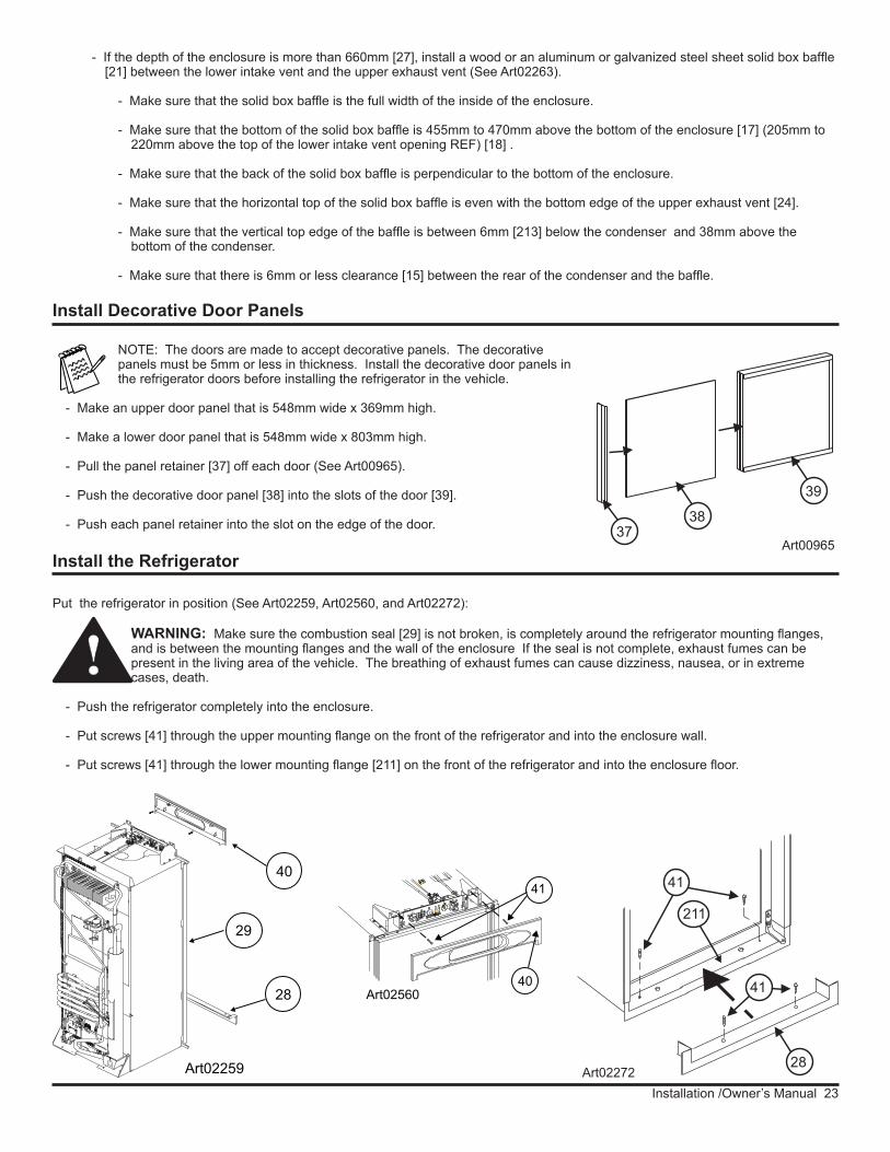
- If the depth of the enclosure is more than 660mm [27], install a wood or an aluminum or galvanized steel sheet solid box baffle [21] between the lower intake vent and the upper exhaust vent (See Art02263).
- Make sure that the solid box baffle is the full width of the inside of the enclosure.
- Make sure that the bottom of the solid box baffle is 455mm to 470mm above the bottom of the enclosure [17] (205mm to 220mm above the top of the lower intake vent opening REF) [18] .
- Make sure that the back of the solid box baffle is perpendicular to the bottom of the enclosure.
- Make sure that the horizontal top of the solid box baffle is even with the bottom edge of the upper exhaust vent [24].
- Make sure that the vertical top edge of the baffle is between 6mm [213] below the condenser and 38mm above the bottom of the condenser.
- Make sure that there is 6mm or less clearance [15] between the rear of the condenser and the baffle.
NOTE: The doors are made to accept decorative panels. The decorative panels must be 5mm or less in thickness. Install the decorative door panels in the refrigerator doors before installing the refrigerator in the vehicle.
- Make an upper door panel that is 548mm wide x 369mm high.
- Make a lower door panel that is 548mm wide x 803mm high.
- Pull the panel retainer [37] off each door (See Art00965).
- Push the decorative door panel [38] into the slots of the door [39].
- Push each panel retainer into the slot on the edge of the door.
Install Decorative Door Panels
Art00965
37
38
39
Put the refrigerator in position (See Art02259, Art02560, and Art02272):
WARNING: Make sure the combustion seal [29] is not broken, is completely around the refrigerator mounting flanges, and is between the mounting flanges and the wall of the enclosure If the seal is not complete, exhaust fumes can be present in the living area of the vehicle. The breathing of exhaust fumes can cause dizziness, nausea, or in extreme cases, death.
- Push the refrigerator completely into the enclosure.
- Put screws [41] through the upper mounting flange on the front of the refrigerator and into the enclosure wall.
- Put screws [41] through the lower mounting flange [211] on the front of the refrigerator and into the enclosure floor.
Install the Refrigerator
Art02560
41
40
29
28
Art02259
40
Art02272
41
28
41
211
Installation / Owner’s Manual 24
WARNING: Do not omit the bottom trim piece. This piece is part of the combustion seal.
- Push the bottom trim piece [28] onto the front of the refrigerator.
- Put two screws [41] through the trim piece, the mounting flange, and into the floor.
- Put screws through mounting flange on the rear of the refrigerator and into the floor.
- Install the upper trim piece [40] over the control panel:
- Align the four (4) metal mounting clips on the back of the upper trim piece with the four (4) rectangular slots in the mounting bracket of the refrigerator.
- Push the upper trim piece firmly until all four (4) mounting clips engage the rectangular slots with a “snap” sound.
!
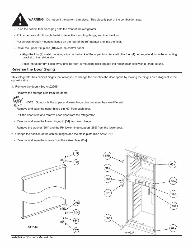
Reverse the Door Swing
This refrigerator has cabinet hinges that allow you to change the direction the door opens by moving the hinges on a diagonal to the opposite side.
1. Remove the doors (See Art02269):
- Remove the storage bins from the doors.
NOTE: Do not mix the upper and lower hinge pins because they are different.
- Remove and save the upper hinge pin [63] from each door.
- Pull the door latch and remove each door from the refrigerator.
- Remove and save the lower hinge pin [64] from each hinge.
- Remove the washer [254] and the RH lower hinge support [255] from the lower door.
2. Change the position of the cabinet hinges and the strike plate (See Art02271):
- Remove and save the screws from the strike plate [65a].
63
66
254
64
67
255
Art02269
65a
67b
66b
66a
67a
65b
66a
67a
66b
67b
Art02271

Installation /Owner’s Manual 25
- Remove the two plastic hole caps that are near the strike plate.
- Remove the L-shaped plastic covers that are opposite the hinges.
- Remove and save the screws from the upper cabinet hinge [66a] of each door.
- Put each of these hinges on the other side of the refrigerator as the lower hinge [66b].
- Attach each of these hinges with screws.
- Remove and save the screws from the lower cabinet hinge [67a] of each door.
- Put each of these hinges on the other side of the refrigerator as the upper hinge [67b].
- Attach each of these hinges with screws.
- Remove and save the screw [41] from the front box [68] (See Art02261).
- Pull the front box away from the refrigerator and out from under the logo box [69].
- Reverse the front box and put it on the opposite side of the logo box.
- Attach the front box to the refrigerator with the screw.
- Put the strike plate on the opposite side of the refrigerator [65b].
- Put the two round plastic caps into the holes that are near the strike plate.
- Put the L-shaped plastic covers over the holes that were used by the hinges.
3. Change the position of the door handles (See Art01727):
- Remove the screws [41] and door handle [70] from each door.
- Reverse each door handle and put the lower door handle on the upper door and the upper door handle on the lower door.
- Attach each door handle with the screws.
4. Reinstall the doors (See Art02273):
- Turn each of the lower hinge pins [64] into the lower cabinet hinges.
NOTE: To prevent damage to the threads of the hinge pins, turn the hinge pins by hand until tight and then tighten with a screwdriver.
CAUTION: Apply Loctite removable thread locker (blue) to the threads of the hinge screws before assembly to prevent loosening during use. Do not allow Loctite to contact any of the plastic surfaces of the refrigerator because it can damage those surfaces.
- Put the washer onto the lower hinge pin of the lower door only
- Put the LH lower hinge support [256] onto the lower hinge of the lower door only.
- Put each door down onto the lower hinge pin.
- Align the holes in the upper hinges and hold in this position.
- Turn the upper hinge pin into the hinges of each door.
- Tighten the hinge pins.
- Put the storage bins in the doors.
41
70
Art01727
!
68
69 41Art02261
63
66
254
64
67
256
Art02273

Installation / Owner’s Manual 26
The current draws are nominal values.
AC Operation 240VAC (216VAC min. - 264VAC max.) Current Draw: AC heater 1.25A at 240VAC
DC Operation 12VDC (11.5VDCmin. - 15.4VDC max.) Current Draw: DC Heater 17.14A at 12VDC DC Heater Relay 0.150A at 12VDC Moisture Reduction heater 0.258A at 12VDC Cooling System Ventilation Fan 0.430A at 12VDC
This refrigerator operates on both AC and DC electrical sources. Operation out of these limits may damage the refrigerator’s electrical circuit parts and will void the warranty.
WARNING: The rear of the refrigerator cooling system has hot surfaces and sharp surfaces that can damage electrical wiring. Make sure that there is a good clearance between all electrical wiring and the cooling system of the refrigerator. Position any electrical wiring within the refrigerator enclosure opposite the burner side of the refrigerator. Do not put any electrical wiring through the roof exhaust vent. Failure to correctly position electrical wiring can result in electrical shock or fire.
Connect the 240 volt AC supply:
WARNING: Connect the AC power cord only to a grounded three-prong power point. Do not remove the earth pin from the power cord. Do not use a two-prong adapter or an extension cord. Operation of the refrigerator without correct ground can cause dangerous electrical shock or death if you are touching the metal parts of the refrigerator.
Put the AC power cord into a grounded three-prong power point:
- Make sure the power point is 100-150mm above the floor of the enclosure and is positioned within easy reach of the lower intake vent.
- Make sure the power cord does not touch the burner cover, the flue pipe, or any hot component that could damage the insulation of the power cord.
Connect the 12 volt DC supply:
As the distance from the vehicle battery to the refrigerator increases, the correct wire size and fuse size also increases. If the wire size is too small for the distance, a voltage drop occurs. The voltage drop decreases the output of the system heater and causes poor cooling performance.
1. Determine the min. wire size and the max. fuse size to use:
WARNING: If you use an incorrect wire size and/or fuse size, electrical fire can result.
- Measure the distance from the vehicle battery to the refrigerator and use the following size wire and fuse:
Distance Min wire size Fuse size 5m 4mm² 30 Amp
8m 6mm² 40 Amp - If the wire is larger than the min. size, use the correct fuse per local codes.
The wire connections must be clean, tight and free of corrosion. If any of these items are not correct:
- A voltage drop to the refrigerator will occur.
- The voltage drop will reduce the cooling performance of the refrigerator.
Connect the Electrical Components
!
!
!

Installation /Owner’s Manual 27
Connect the Propane Gas Components
This refrigerator operates on propane gas at a pressure of 2.7kPa propane. The refrigerator gas usage is 1.5 MJ/h.Connect the propane gas supply system:
WARNING: Be very careful when working on or near the propane gas system.
- Do not smoke or use an open flame near the propane gas system.
- Do not use an open flame to examine for leaks.
- Do not connect the refrigerator to the propane gas tank without a pressure regulator between them.
- To avoid a propane gas leak, always use two wrenches to tighten or loosen the gas supply line connections.
- Leaking propane gas can ignite or explode and result in dangerous personal injury or death.
Connect the gas supply line to the refrigerator:
- Make sure all tubing and fittings obey all local, state, and national codes about size and type.
- Use of 3/8 inch copper tubing as the gas supply line and a 3/8 inch SAE (UNF 5/8-18) male flare fitting as the connection to the refrigerator.
- Put the propane gas supply line up through the floor of the enclosure.
- Make sure the hole through the floor is large enough to allow clearance for the gas supply line.
- Put a weather resistant seal (grommet, sealant, etc.) around the gas supply line where it goes through the floor to prevent vibration and abrasion.
- To prevent vibration and abrasion, make sure that the gas supply line is not against anything in the enclosure.
- Attach the gas supply line to the manual shutoff valve [218] of the refrigerator (See Art02258).
Examine the gas supply system for leaks:
WARNING: Do not allow the leak detecting solution to touch the electrical components. Many liquids are electrically conductive and can cause a shock hazard, electrical shorts, and in some cases, fire.
Use a leak detecting solution to examine the gas supply line and all propane gas connections for leaks.
!
!
The terminals for connecting the DC power supply are marked positive (+) and negative (-). Make sure that:
- Each DC power supply wire is attached to the correct polarity terminal.
- The chassis or the vehicle frame is not used as one of the conductors.
- The DC power supply wires including the fuses are routed directly from the battery to the refrigerator.
2. Connect the D.C. power supply wires:
- Attach a fully insulated 6.35 mm Quick Connect terminal to each DC power supply wire.
- Push the positive (+) DC power wire onto the red DC wire.
- Push the negative (-) DC power wire onto the black DC heater wire.
- Make sure each DC power supply wire is on the correct polarity terminal.
Art02258218165
Installation / Owner’s Manual 28
If you use compressed air for the test:
- The pressure at the manual shut off valve of the refrigerator must not be more than 3.5 kPa.
- If the air pressure is more than 3.5 kPa, remove the gas supply line from the bulkhead fitting of the refrigerator before the test.
- If the air pressure is equal to or less than 3.5 kPa, close the manual shutoff valve of the refrigerator before the test.
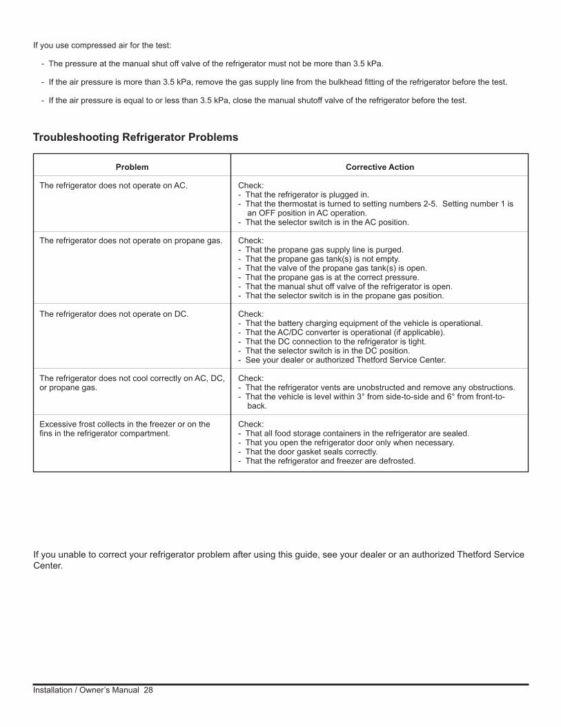
Troubleshooting Refrigerator Problems
If you unable to correct your refrigerator problem after using this guide, see your dealer or an authorized Thetford Service Center.
Problem
The refrigerator does not operate on AC.
The refrigerator does not operate on propane gas.
The refrigerator does not operate on DC.
The refrigerator does not cool correctly on AC, DC, or propane gas.
Excessive frost collects in the freezer or on the fins in the refrigerator compartment.
Corrective Action
Check:- That the refrigerator is plugged in.- That the thermostat is turned to setting numbers 2-5. Setting number 1 is an OFF position in AC operation.- That the selector switch is in the AC position.
Check:- That the propane gas supply line is purged.- That the propane gas tank(s) is not empty.- That the valve of the propane gas tank(s) is open.- That the propane gas is at the correct pressure.- That the manual shut off valve of the refrigerator is open.- That the selector switch is in the propane gas position.
Check:- That the battery charging equipment of the vehicle is operational.- That the AC/DC converter is operational (if applicable).- That the DC connection to the refrigerator is tight.- That the selector switch is in the DC position.- See your dealer or authorized Thetford Service Center.
Check:- That the refrigerator vents are unobstructed and remove any obstructions.- That the vehicle is level within 3° from side-to-side and 6° from front-to- back.
Check:- That all food storage containers in the refrigerator are sealed.- That you open the refrigerator door only when necessary.- That the door gasket seals correctly.- That the refrigerator and freezer are defrosted.