INSTALLATION AND OWNER’S MANUAL - Fireplace X · PDF fileELECTRIC FIREPLACE INSERT...
19
1 ELECTRIC FIREPLACE INSERT INSTALLATION AND OWNER’S MANUAL Small Fireplace Insert (38” Wide) 98501001 Medium Fireplace Insert (40” Wide) 98501002 Large Fireplace Insert (42” Wide) 98501003 malfunction and result in serious injury and/or property damage. WARNING: All electric heaters have hot or sparking parts inside. Do not use it in areas where gasoline, paint or flammable liquids are stored. and/or result in a safety hazard. Read these instructions completely before beginning installation. Failure to follow them could cause a heater WARNING: This heater is tested and listed for use only with the optional accessories listed in these instructions. Use of optional accessories not specifically tested for this heater could void the heater warranty
Transcript of INSTALLATION AND OWNER’S MANUAL - Fireplace X · PDF fileELECTRIC FIREPLACE INSERT...
1
ELECTRIC FIREPLACE INSERT
INSTALLATION AND OWNER’S MANUAL
Small Fireplace Insert (38” Wide) 98501001
Medium Fireplace Insert (40” Wide) 98501002
Large Fireplace Insert (42” Wide) 98501003
malfunction and result in serious injury and/or property damage.
WARNING: All electric heaters have hot or sparking parts inside. Do not use it in areas where gasoline, paint or flammable liquids are stored.
and/or result in a safety hazard.
Read these instructions completely before beginning installation. Failure to follow them could cause a heater
WARNING: This heater is tested and listed for use only with the optional accessories listed inthese instructions. Use of optional accessories not specifically tested for this heater could void the heater warranty
2
Keep this manual for future reference.
SAFETY INFORMATION
When using electrical heaters, basic precautions, like the ones listed below, should always be followed in order to
reduce the risk of fire, electric shock and injury.
1. Read all instructions before using this heater.
2. Keep combustible materials, such as furniture, pillows, bedding, papers, clothes and curtains at least 3 feet from the
front of the heater; keep them away from sides and rear as well.
3. Always unplug heater when it’s not in use.
4. Do not operate the fireplace insert if it has a damaged cord or plug, after it has malfunctioned, or if the unit has been
dropped or damaged in any way. 5. Do not use the heater outdoors.
6. This heater is not intended for use in bathrooms, laundry areas and similar indoor locations. Never place the heater
where it may fall into a bathtub or other water containers.
7. Do not run the cord under carpeting. Do not cover the cord with throw rugs, runners or anything else. Arrange the
cord away from traffic areas where it could be tripped over.
8. To disconnect the heater, turn the controls to "OFF" before removing the plug from the outlet.
9. Do not insert or allow foreign objects to enter any ventilation or exhaust opening, as this may cause an electric
shock, fire or damage to the heater.
10. To prevent a possible fire, do not block air intakes in any manner.
11. A heater has hot or sparking parts inside. Do not use it in areas where gasoline, paint or flammable
liquids are used or stored.
Due to high temperatures, the insert should be located out of traffic and away from furniture and draperies.
The insert can become very hot when running. Keep children and adults away from hot surfaces to avoid burns or clothing ignition. The insert will remain hot for a time after shutdown. Allow surfaces to coolbefore touching.
Do not place clothing or other flammable material on or near the insert. Never place any objects on the insert.
3
12. Use this heater only as described in this manual. Any other use not recommended by the manufacturer may cause
fire, electric shock or injury to persons.
13. Avoid the use of an extension cord because the extension cord may overheat and cause a fire. If you have to use
an extension cord, the cord should be No. 14 AWG minimum size and rated not less than 1875 WATTS.
14. Always use a properly grounded, protected (fuse or circuit breaker), and polarized outlet.
15. Always use ground fault protection where it is required by electrical codes.
16. Always disconnect the power before performing any cleaning, maintenance or relocation of the heater.
17. To prevent a possible fire, do not burn wood or other materials in this heater.
18 To prevent electric shock or fire, always use a certified electrician, should new circuits or outlets
be required.
19. When transporting or storing the heater, keep it in a dry place, free from excessive vibration.
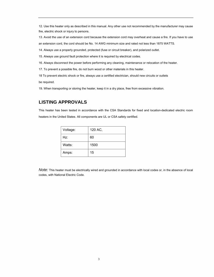
LISTING APPROVALS This heater has been tested in accordance with the CSA Standards for fixed and location-dedicated electric room
heaters in the United States. All components are UL or CSA safety certified.
Voltage: 120 AC,
Hz: 60
Watts: 1500
Amps: 15
Note: This heater must be electrically wired and grounded in accordance with local codes or, in the absence of local codes, with National Electric Code.
4
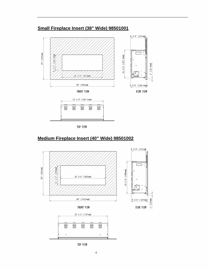
Small Fireplace Insert (38” Wide) 98501001
Medium Fireplace Insert (40” Wide) 98501002
16 3/4" [427.8mm]
9 3/4" [246.8mm]
25 1/4" [641.6mm]
1" [25.4mm]
9 1/2" [241.9mm]
24 1/4" [613mm]
8 3/4" [221mm]
25" [635mm]
38" [965mm]
40" [1015mm]
26" [661mm]
29 1/2" [747mm]
19 1/4" [488mm]
9 3/4" [247mm]
26 3/4" [682mm]
1" [25mm]
11 1/2" [293mm]
8 3/4" [221mm]
5
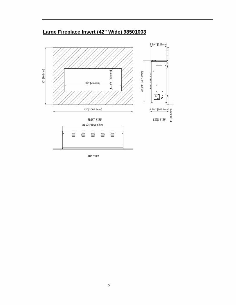
Large Fireplace Insert (42” Wide) 98501003
42" [1066.8mm]
31 3/4" [806.6mm]
22 1
/4" [
567.
8mm
]
30" [
762m
m]
1" [2
5.6m
m]9 3/4" [246.8mm]
30" [762mm]
11 3
/4" [
298m
m]
8 3/4" [221mm]
6
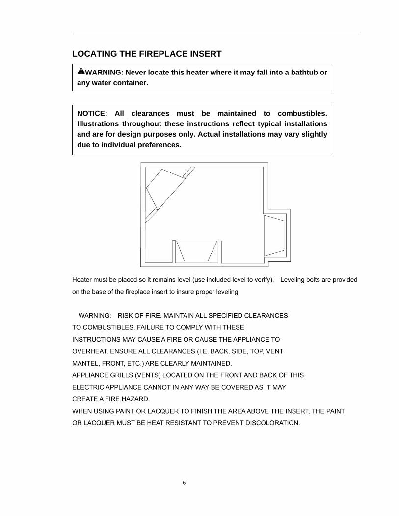
LOCATING THE FIREPLACE INSERT
Heater must be placed so it remains level (use included level to verify). Leveling bolts are provided
on the base of the fireplace insert to insure proper leveling.
WARNING: RISK OF FIRE. MAINTAIN ALL SPECIFIED CLEARANCES
TO COMBUSTIBLES. FAILURE TO COMPLY WITH THESE
INSTRUCTIONS MAY CAUSE A FIRE OR CAUSE THE APPLIANCE TO
OVERHEAT. ENSURE ALL CLEARANCES (I.E. BACK, SIDE, TOP, VENT
MANTEL, FRONT, ETC.) ARE CLEARLY MAINTAINED.
APPLIANCE GRILLS (VENTS) LOCATED ON THE FRONT AND BACK OF THIS
ELECTRIC APPLIANCE CANNOT IN ANY WAY BE COVERED AS IT MAY
CREATE A FIRE HAZARD.
WHEN USING PAINT OR LACQUER TO FINISH THE AREA ABOVE THE INSERT, THE PAINT
OR LACQUER MUST BE HEAT RESISTANT TO PREVENT DISCOLORATION.
NOTICE: All clearances must be maintained to combustibles. Illustrations throughout these instructions reflect typical installations and are for design purposes only. Actual installations may vary slightly due to individual preferences.
WARNING: Never locate this heater where it may fall into a bathtub or any water container.
7
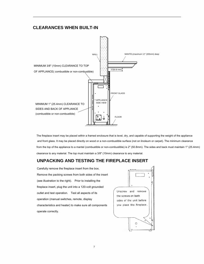
CLEARANCES WHEN BUILT-IN
UNPACKING AND TESTING THE FIREPLACE INSERT Carefully remove the fireplace insert from the box.
Remove the packing screws from both sides of the insert
(see illustration to the right). Prior to installing the
fireplace insert, plug the unit into a 120-volt grounded
outlet and test operation. Test all aspects of its
operation (manual switches, remote, display
characteristics and heater) to make sure all components
operate correctly.
WALL MANTEL(maximum 12" (305mm) deep
FLOOR
FRONT GLASS
APPLIANCESIDE VIEW
2"[50.8 mm]
The fireplace insert may be placed within a framed enclosure that is level, dry, and capable of supporting the weight of the appliance
and front glass. It may be placed directly on wood or a non-combustible surface (not on linoleum or carpet). The minimum clearance
from the top of the appliance to a mantel (combustible or non-combustible) is 2" (50.8mm). The sides and back must maintain 1" (25.4mm)
clearance to any material. The top must maintain a 3/8" (10mm) clearance to any material.
MINIMUM 3/8" (10mm) CLEARANCE TO TOP
OF APPLIANCE( combustible or non-combustible)
MINIMUM 1" (25.4mm) CLEARANCE TO
SIDES AND BACK OF APPLIANCE
(combustible or non-combustible)
8
INSTALLATION
CAUTION: The unit's power supply cord must be connected to a properly grounded and protected 120-volt outlet. Always use ground fault protection where required by the electrical code.
WARNING - RISK OF FIRE! To prevent a possible fire, do not block the grills, louvers, or air openings on the fireplace insert in any manner.
WARNING - RISK OF FIRE! The power cord must not be pinched or placed against a sharp edge. Secure the cord to avoid tripping or snagging thus reducing the risk of fire, electric shock or personal injury. Do not run the cord under carpeting. Do not cover the cord with throw rugs, runners or similar items. Arrange the cord away from traffic areas where it could be tripped over.
Select a suitable location that is not susceptible to moisture and is away from drapes, furniture and high traffic areas.
Note: Follow all national and local electrical codes.
9
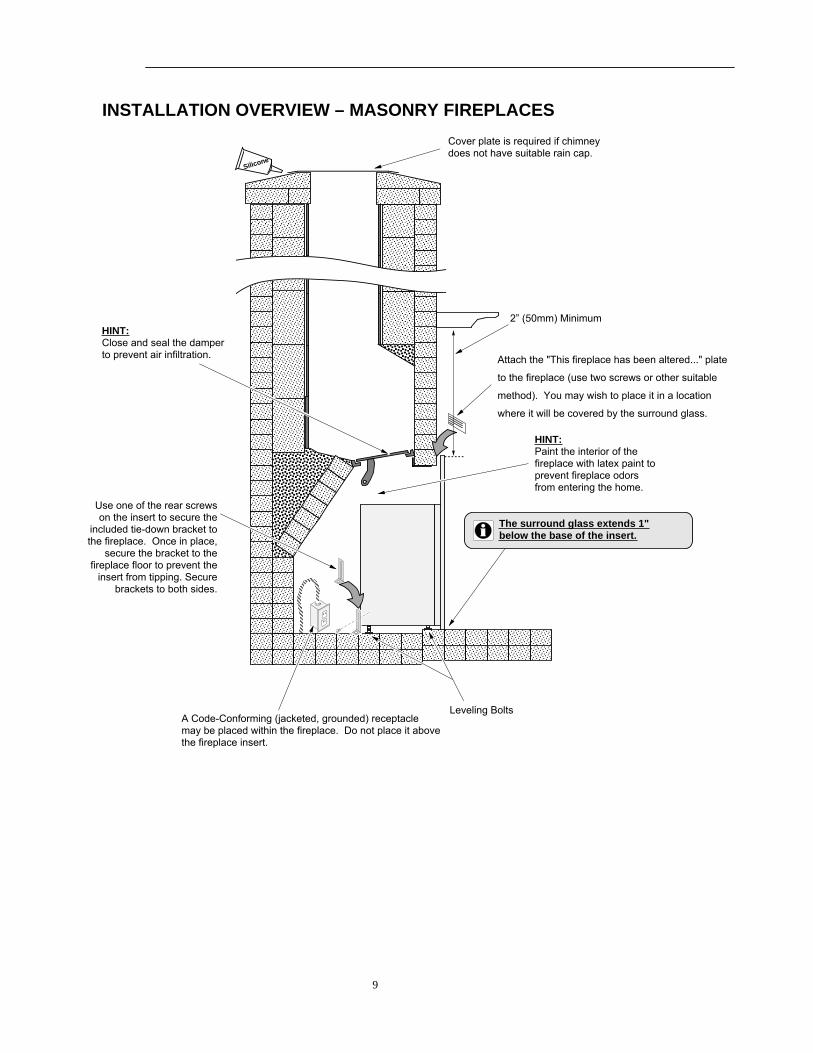
INSTALLATION OVERVIEW – MASONRY FIREPLACES
2” (50mm) Minimum
�����������
������
HINT:Paint the interior of the fireplace with latex paint to prevent fireplace odors from entering the home.
Silicone
������������
����
�����������������������������������
������������������������������������������������������
������������������������������������������������������������������������������������������������������������������������������
����������������������������������������������
������������������������������������������������
������������������������������������������������
���������������������������
����������
��������
������
���� ����
����
����������
��������������������
���������������
Leveling Bolts
HINT:Close and seal the damper to prevent air infiltration.
Cover plate is required if chimney does not have suitable rain cap.
A Code-Conforming (jacketed, grounded) receptacle may be placed within the fireplace. Do not place it above the fireplace insert.
The surround glass extends 1"below the base of the insert.
Attach the "This fireplace has been altered..." plate
to the fireplace (use two screws or other suitable
method). You may wish to place it in a location
where it will be covered by the surround glass.
Use one of the rear screws on the insert to secure the
included tie-down bracket to the fireplace. Once in place,
secure the bracket to the fireplace floor to prevent the
insert from tipping. Secure brackets to both sides.
10
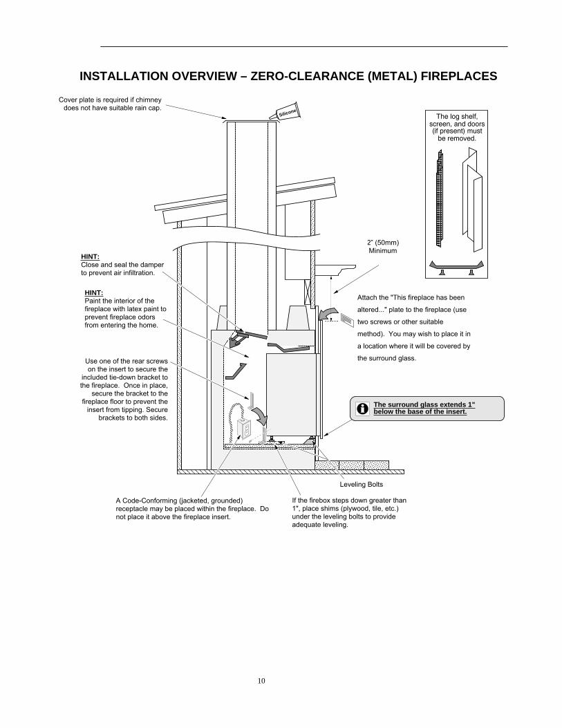
INSTALLATION OVERVIEW – ZERO-CLEARANCE (METAL) FIREPLACES
���������������������
���������
2” (50mm) Minimum
��������
������
������
�������������������������������������������������������������������������������������������������
�����������������
�����������������
�����������������
����
��������
������
����������������
����������������
������������������
����������������������������������������������������������������������
The log shelf, screen, and doors (if present) must
be removed.
�������
����������������
��������������
��������������
�������
������
��������������
��������������
�������
������
��������������
��������������
HINT:Paint the interior of the fireplace with latex paint to prevent fireplace odors from entering the home.
HINT:Close and seal the damper to prevent air infiltration.
Cover plate is required if chimney does not have suitable rain cap.
������
If the firebox steps down greater than 1", place shims (plywood, tile, etc.) under the leveling bolts to provide adequate leveling.
Silicone
The surround glass extends 1"below the base of the insert.
��������
����
���
A Code-Conforming (jacketed, grounded) receptacle may be placed within the fireplace. Do not place it above the fireplace insert.
Leveling Bolts
Attach the "This fireplace has been
altered..." plate to the fireplace (use
two screws or other suitable
method). You may wish to place it in
a location where it will be covered by
the surround glass.Use one of the rear screws on the insert to secure the
included tie-down bracket to the fireplace. Once in place,
secure the bracket to the fireplace floor to prevent the
insert from tipping. Secure brackets to both sides.
11
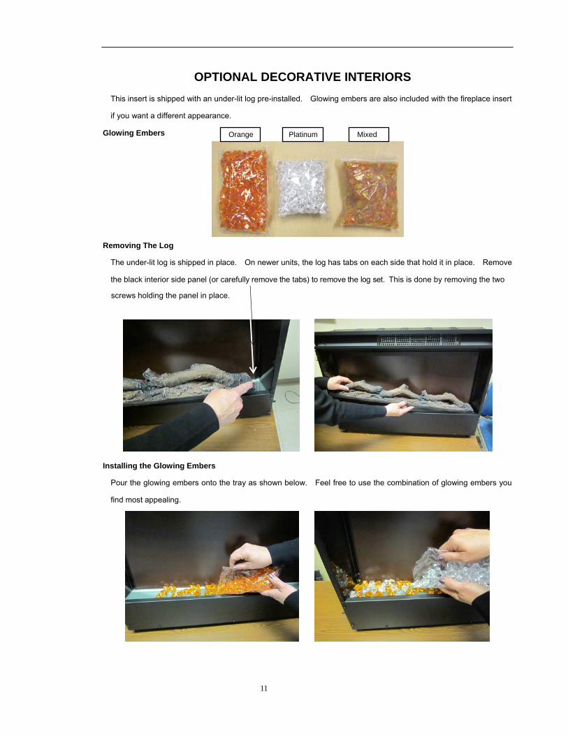
OPTIONAL DECORATIVE INTERIORS
This insert is shipped with an under-lit log pre-installed. Glowing embers are also included with the fireplace insert
if you want a different appearance.
Glowing Embers
Removing The Log
The under-lit log is shipped in place. On newer units, the log has tabs on each side that hold it in place. Remove
Installing the Glowing Embers
Pour the glowing embers onto the tray as shown below. Feel free to use the combination of glowing embers you
find most appealing.
Orange Platinum Mixed
the black interior side panel (or carefully remove the tabs) to remove the log set. This is done by removing the two
screws holding the panel in place.
12
OPERATING INSTRUCTIONS
REMOVING THE SURROUND GLASS
Before removing the surround glass, make sure to have a suitable location to place the surround glass once it is
removed. Do not place the glass on sharp or uneven areas that may chip or damage the tempered glass. Use both
hands to lift the surround glass directly up. The hooks on the glass will disengage from the pins that protrude from
the side of the insert.
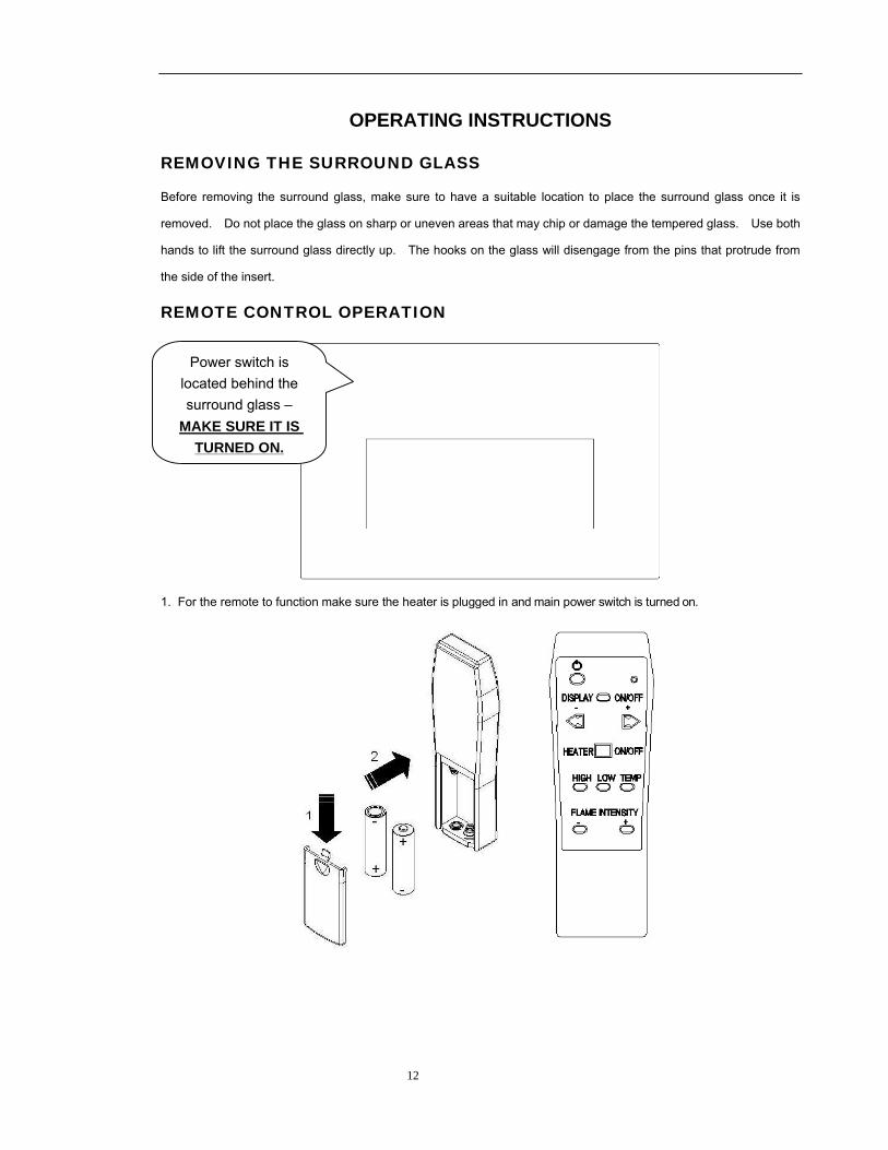
REMOTE CONTROL OPERATION
1. For the remote to function make sure the heater is plugged in and main power switch is turned on.
Power switch is located behind the surround glass –
MAKE SURE IT IS TURNED ON.
13
REMOTE CONTROL OPERATION (continued) Note. The remote control requires 2 AA batteries (not included).
Note: The heater may release a slight odor the first time it is turned on. This is normal. The heating
elements inside the heater will burn off any accumulated oils or dust during initial heating. This may also
occur when dust accumulates on the heating elements over periods of non-use.
2. When operating the remote make sure to point the remote at the center of the fireplace insert. Each time you press
a button on the remote the LED indicator on the top right of the remote should blink and the fireplace insert will “BEEP”.
If the LED fails to blink check the batteries. It takes up to one second for the fireplace insert to respond to the
transmitter. DO NOT PRESS THE BUTTONS MORE THAN ONCE within two seconds. This allows the fireplace
insert to respond to the remote.
3. Power on button: The power – on button at top left corner of the remote is the main ON/ OFF power button. This will turn off all the functions (heater and display). If you turn the fireplace insert OFF, then ON, the fireplace insert will return to its last heater and display settings.
4. Flame Power On button ” DISPLAY ON OFF ”: This button controls both the ember and flame effect. Once the
flame effect is ON use the + and – buttons as explained below to adjust the flame brightness as desired. Press this
button again to turn OFF the flame effect.
a. The – or + buttons control the brightness of EMBER.
To increase the brightness of ember bed, press and release the + button. Each time you press this button
the brightness will increase small amount, until the maximum is reached.
To decrease the brightness of ember bed, press and release the – button. Each time you press this button
the brightness will decrease a small amount, until the minimum brightness is reached.
b. The FLAME INTENSITY– or + buttons control the brightness of FLAME.
To increase the brightness / flame Intensity, press and release the + button. Each time you press this
button the brightness will increase by a small amount, until the maximum is reached.
To decrease the brightness / flame Intensity, press and release the – button . Each time you press this
button the brightness will decrease by small amount, unitl the minimum brightness is reached. You can mix the
ember and the flame to create a realistic flame effect.
14
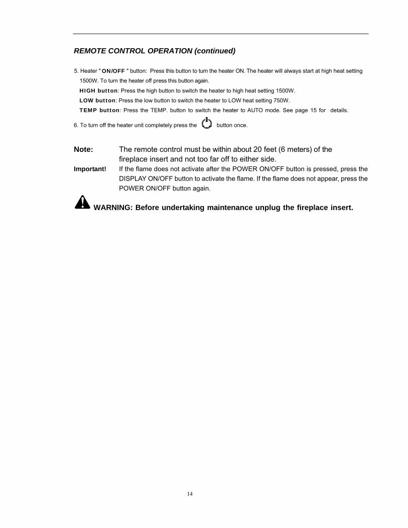
REMOTE CONTROL OPERATION (continued) 5. Heater " " button: Press this button to turn the heater ON. The heater will always start at high heat setting
1500W. To turn the heater off press this button again.
HIGH button: Press the high button to switch the heater to high heat setting 1500W.
LOW button: Press the low button to switch the heater to LOW heat setting 750W.
TEMP button: Press the TEMP. button to switch the heater to AUTO mode. See page 15 for details.
6. To turn off the heater unit completely press the button once.
Note: The remote control must be within about 20 feet (6 meters) of the fireplace insert and not too far off to either side.
Important! If the flame does not activate after the POWER ON/OFF button is pressed, press the DISPLAY ON/OFF button to activate the flame. If the flame does not appear, press the POWER ON/OFF button again.
WARNING: Before undertaking maintenance unplug the fireplace insert.
ON/OFF
15
DIRECT OPERATION
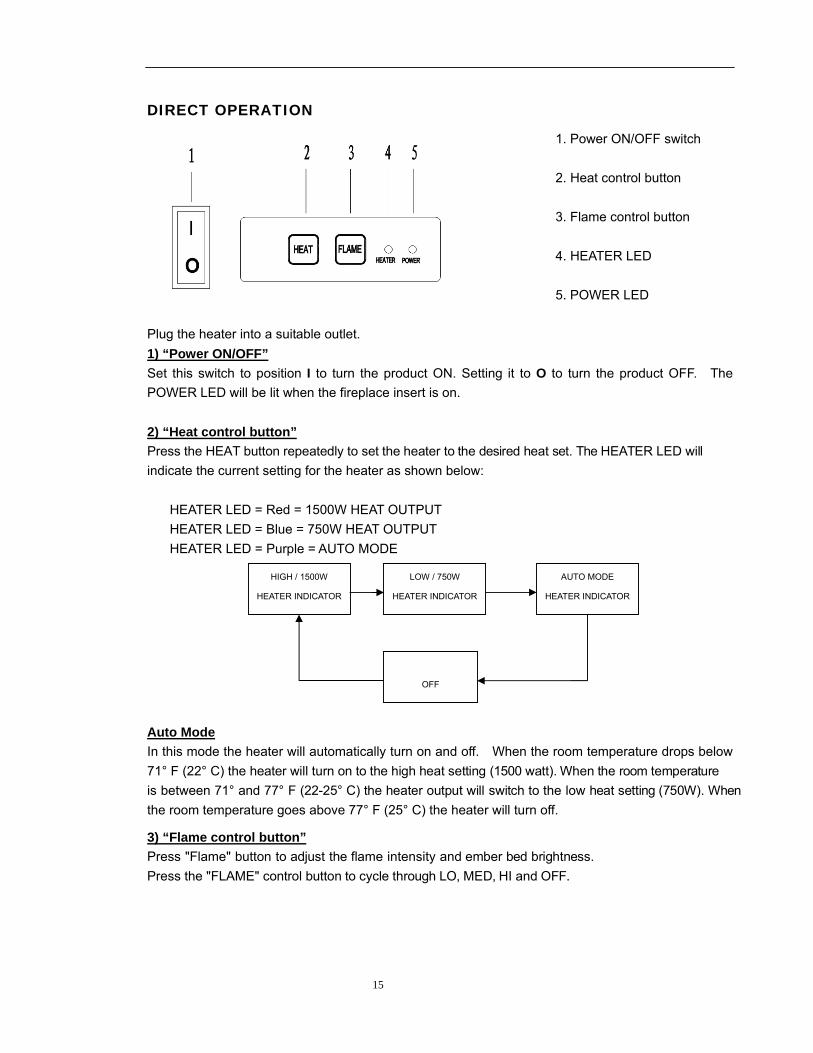
1. Power ON/OFF switch 2. Heat control button 3. Flame control button 4. HEATER LED 5. POWER LED
Plug the heater into a suitable outlet. 1) “Power ON/OFF” Set this switch to position I to turn the product ON. Setting it to O to turn the product OFF. The POWER LED will be lit when the fireplace insert is on. 2) “Heat control button” Press the HEAT button repeatedly to set the heater to the desired heat set. The HEATER LED will indicate the current setting for the heater as shown below:
HEATER LED = Red = 1500W HEAT OUTPUT HEATER LED = Blue = 750W HEAT OUTPUT HEATER LED = Purple = AUTO MODE
Auto Mode In this mode the heater will automatically turn on and off. When the room temperature drops below 71° F (22° C) the heater will turn on to the high heat setting (1500 watt). When the room temperature is between 71° and 77° F (22-25° C) the heater output will switch to the low heat setting (750W). When the room temperature goes above 77° F (25° C) the heater will turn off.
3) “Flame control button” Press "Flame" button to adjust the flame intensity and ember bed brightness. Press the "FLAME" control button to cycle through LO, MED, HI and OFF.
HIGH / 1500W
HEATER INDICATOR
LOW / 750W
HEATER INDICATOR
AUTO MODE
HEATER INDICATOR
OFF
16
CLEANING AND MAINTENANCE
FRONT GLASS
1. Remove dust by buffing lightly with a clean dry cloth.
2. To remove fingerprints or other marks, the glass can be cleaned with a damp cloth using a good quality household
glass cleaner. The glass should be completely dried with a lint free cloth or paper towel.
3. In the event of glass breakage, vacuum all remaining glass pieces with a shop vac. DO NOT VACUUM WHILE THE
PIECES ARE HOT. Replace glass only with replacement parts made specifically for this heater. Never substitute
material.
WARNING: Always disconnect the power and allow the heater to cool before performing any cleaning, maintenance or relocation. Turn the controls to OFF and remove the plug from the outlet or turn off the circuit breaker before attempting any cleaning.

17
REPLACEMENT PARTS REF NO PART NO. DESCRIPTION REMARK
1
1
2 3
4
14
5 6
7
9 10
11
12
13
8
HEATER ASSEMBLY250-02868
CIRCULT BOART250-028692
REMOTE RECEIVER250-028703
3W LED ASSEMBLY250-028714
LED STRIP FOR FLAME250-028725
LED STRIP FOR FLAME250-028736
LED STRIP FOR LOG250-028747
LED STRIP FOR LOG250-028758
LED STRIP FOR EMBER250-028769
LED STRIP FOR EMBER250-0287710REMOTE250-0287811
FLAME MOTOR250-0289712SWITCH250-0288013
38 INS LOG250-0288114
40 INS LOG250-02882
42 INS LOG250-02883
18
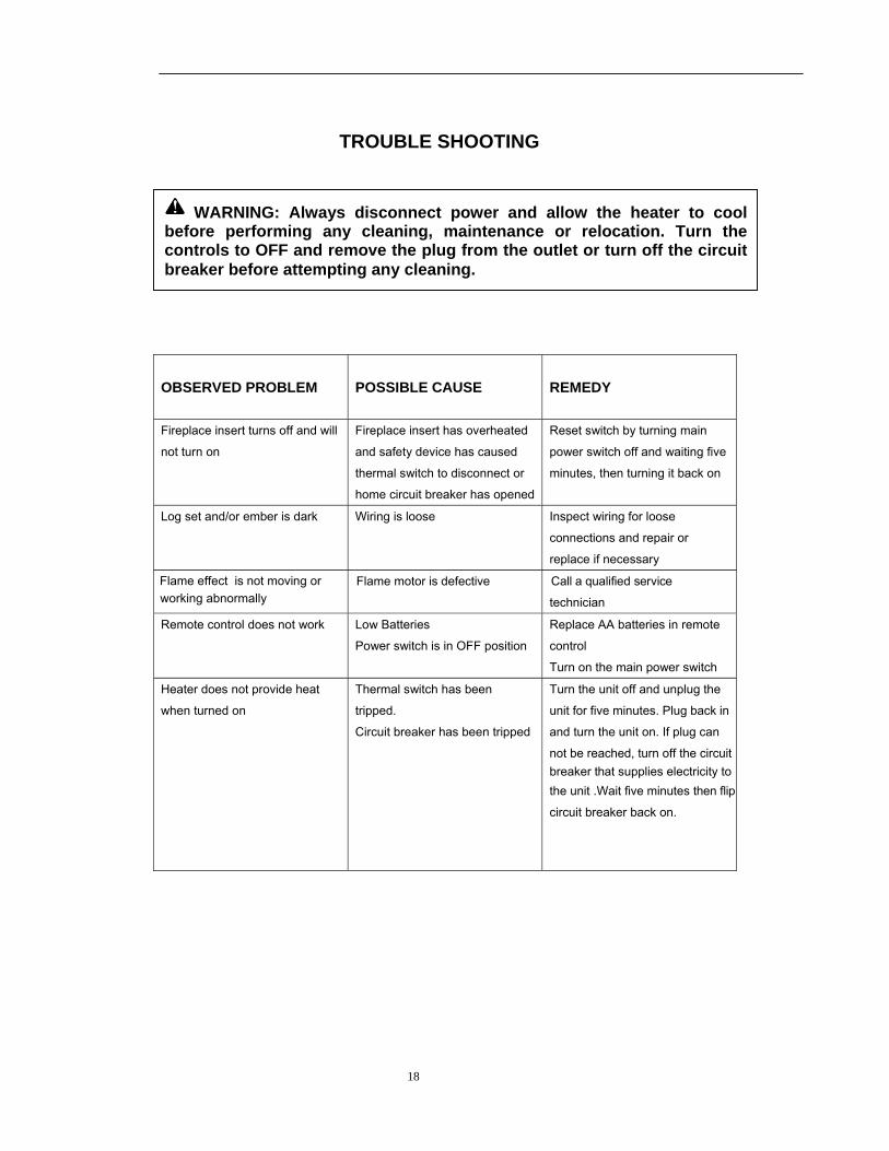
TROUBLE SHOOTING
OBSERVED PROBLEM
POSSIBLE CAUSE
REMEDY
Fireplace insert turns off and will
not turn on Fireplace insert has overheated
and safety device has caused
thermal switch to disconnect or
home circuit breaker has opened
Reset switch by turning main
power switch off and waiting five
minutes, then turning it back on
Log set and/or ember is dark Wiring is loose Inspect wiring for loose
connections and repair or
replace if necessary
Flame motor is defective Call a qualified service
technician
Remote control does not work Low Batteries
Power switch is in OFF position
Replace AA batteries in remote
control
Turn on the main power switch
Heater does not provide heat
when turned on
Thermal switch has been
tripped.
Circuit breaker has been tripped
Turn the unit off and unplug the
unit for five minutes. Plug back in
and turn the unit on. If plug can
not be reached, turn off the circuit breaker that supplies electricity to the unit .Wait five minutes then flip
circuit breaker back on.
WARNING: Always disconnect power and allow the heater to cool before performing any cleaning, maintenance or relocation. Turn the controls to OFF and remove the plug from the outlet or turn off the circuit breaker before attempting any cleaning.
Flame effect is not moving or working abnormally
19
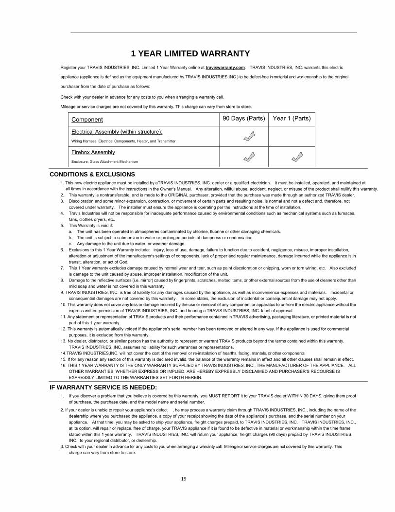
1 YEAR LIMITED WARRANTY Register your TRAVIS INDUSTRIES, INC. Limited 1 Year Warranty online at traviswarranty.com. TRAVIS INDUSTRIES, INC. warrants this electric
appliance (appliance is defined as the equipment manufactured by TRAVIS INDUSTRIES,INC.) to be defect-free in material and workmanship to the original
purchaser from the date of purchase as follows:
Check with your dealer in advance for any costs to you when arranging a warranty call.
Mileage or service charges are not covered by this warranty. This charge can vary from store to store.
Component 90 Days (Parts) Year 1 (Parts)
Electrical Assembly (within structure): Wiring Harness, Electrical Components, Heater, and Transmitter
Firebox Assembly Enclosure, Glass Attachment Mechanism
CONDITIONS & EXCLUSIONS 1. This new electric appliance must be installed by aTRAVIS INDUSTRIES, INC. dealer or a qualified electrician. It must be installed, operated, and maintained at
all times in accordance with the instructions in the Owner’s Manual. Any alteration, willful abuse, accident, neglect, or misuse of the product shall nullify this warranty. 2. This warranty is nontransferable, and is made to the ORIGINAL purchaser, provided that the purchase was made through an authorized TRAVIS dealer. 3. Discoloration and some minor expansion, contraction, or movement of certain parts and resulting noise, is normal and not a defect and, therefore, not
covered under warranty. The installer must ensure the appliance is operating per the instructions at the time of installation. 4. Travis Industries will not be responsible for inadequate performance caused by environmental conditions such as mechanical systems such as furnaces,
fans, clothes dryers, etc. 5. This Warranty is void if:
a. The unit has been operated in atmospheres contaminated by chlorine, fluorine or other damaging chemicals. b. The unit is subject to submersion in water or prolonged periods of dampness or condensation. c. Any damage to the unit due to water, or weather damage.
6. Exclusions to this 1 Year Warranty include: injury, loss of use, damage, failure to function due to accident, negligence, misuse, improper installation, alteration or adjustment of the manufacturer's settings of components, lack of proper and regular maintenance, damage incurred while the appliance is in transit, alteration, or act of God.
7. This 1 Year warranty excludes damage caused by normal wear and tear, such as paint discoloration or chipping, worn or torn wiring, etc. Also excluded is damage to the unit caused by abuse, improper installation, modification of the unit.
8. Damage to the reflective surfaces (i.e. mirror) caused by fingerprints, scratches, melted items, or other external sources from the use of cleaners other than mild soap and water is not covered in this warranty.
9. TRAVIS INDUSTRIES, INC. is free of liability for any damages caused by the appliance, as well as inconvenience expenses and materials. Incidental or consequential damages are not covered by this warranty. In some states, the exclusion of incidental or consequential damage may not apply.
10. This warranty does not cover any loss or damage incurred by the use or removal of any component or apparatus to or from the electric appliance without the express written permission of TRAVIS INDUSTRIES, INC. and bearing a TRAVIS INDUSTRIES, INC. label of approval.
11. Any statement or representation of TRAVIS products and their performance contained in TRAVIS advertising, packaging literature, or printed material is not part of this 1 year warranty.
12. This warranty is automatically voided if the appliance’s serial number has been removed or altered in any way. If the appliance is used for commercial purposes, it is excluded from this warranty.
13. No dealer, distributor, or similar person has the authority to represent or warrant TRAVIS products beyond the terms contained within this warranty. TRAVIS INDUSTRIES, INC. assumes no liability for such warranties or representations.
14.TRAVIS INDUSTRIES,INC. will not cover the cost of the removal or re-installation of hearths, facing, mantels, or other components. 15. If for any reason any section of this warranty is declared invalid, the balance of the warranty remains in effect and all other clauses shall remain in effect. 16. THIS 1 YEAR WARRANTY IS THE ONLY WARRANTY SUPPLIED BY TRAVIS INDUSTRIES, INC., THE MANUFACTURER OF THE APPLIANCE. ALL
OTHER WARRANTIES, WHETHER EXPRESS OR IMPLIED, ARE HEREBY EXPRESSLY DISCLAIMED AND PURCHASER’S RECOURSE IS EXPRESSLY LIMITED TO THE WARRANTIES SET FORTH HEREIN.
IF WARRANTY SERVICE IS NEEDED: 1. If you discover a problem that you believe is covered by this warranty, you MUST REPORT it to your TRAVIS dealer WITHIN 30 DAYS, giving them proof
of purchase, the purchase date, and the model name and serial number.
2. If your dealer is unable to repair your appliance’s defect , he may process a warranty claim through TRAVIS INDUSTRIES, INC., including the name of the dealership where you purchased the appliance, a copy of your receipt showing the date of the appliance’s purchase, and the serial number on your appliance. At that time, you may be asked to ship your appliance, freight charges prepaid, to TRAVIS INDUSTRIES, INC. TRAVIS INDUSTRIES, INC., at its option, will repair or replace, free of charge, your TRAVIS appliance if it is found to be defective in material or workmanship within the time frame stated within this 1 year warranty. TRAVIS INDUSTRIES, INC. will return your appliance, freight charges (90 days) prepaid by TRAVIS INDUSTRIES, INC., to your regional distributor, or dealership.
3. Check with your dealer in advance for any costs to you when arranging a warranty call. Mileage or service charges are not covered by this warranty. This charge can vary from store to store.