Installation and Operation - Trane · PDF file · 2018-03-02NEC and your...
40
SAFETY WARNING Only qualified personnel should install and service the equipment. The installation, starting up, and servicing of heating, ventilating, and air-conditioning equipment can be hazardous and requires specific knowledge and training. Improperly installed, adjusted or altered equipment by an unqualified person could result in death or serious injury. When working on the equipment, observe all precautions in the literature and on the tags, stickers, and labels that are attached to the equipment. December 2013 Installation and Operation Variable Refrigerant Flow (VRF) System Touchscreen Control Models: TVCTRLTCMA300T VRF-SVX37A-EN
Transcript of Installation and Operation - Trane · PDF file · 2018-03-02NEC and your...

SAFETY WARNINGOnly qualified personnel should install and service the equipment. The installation, starting up, and servicing of heating, ventilating, and air-conditioning equipment can be hazardous and requires specific knowledge and training. Improperly installed, adjusted or altered equipment by an unqualified person could result in death or serious injury. When working on the equipment, observe all precautions in the literature and on the tags, stickers, and labels that are attached to the equipment.
December 2013
Installation and Operation
Variable Refrigerant Flow (VRF) System
Touchscreen Control
Models: TVCTRLTCMA300T
VRF-SVX37A-EN

2 VRF-SVX37A-EN
Introduction
Read this manual thoroughly before operating or servicing this unit.
Warnings, Cautions, and Notices
Safety advisories appear throughout this manual as required. Your personal safety and the proper operation of this machine depend upon the strict observance of these precautions.
Important Environmental Concerns
Scientific research has shown that certain man-made chemicals can affect the earth’s naturally occurring stratospheric ozone layer when released to the atmosphere. In particular, several of the identified chemicals that may affect the ozone layer are refrigerants that contain Chlorine, Fluorine and Carbon (CFCs) and those containing Hydrogen, Chlorine, Fluorine and Carbon (HCFCs). Not all refrigerants containing these compounds have the same potential impact to the environment. Trane advocates the responsible handling of all refrigerants-including industry replacements for CFCs such as HCFCs and HFCs.
Important Responsible Refrigerant Practices
Trane believes that responsible refrigerant practices are important to the environment, our customers, and the air conditioning industry. All technicians who handle refrigerants must be certified. The Federal Clean Air Act (Section 608) sets forth the requirements for handling, reclaiming, recovering and recycling of certain refrigerants and the equipment that is used in these service procedures. In addition, some states or municipalities may have additional requirements that must also be adhered to for responsible management of refrigerants. Know the applicable laws and follow them.
Copyright
This document and the information in it are the property of Trane and may not be used or reproduced in whole or in part, without the written permission of Trane. Trane reserves the right to revise this publication at any time and to make changes to its content without obligation to notify any person of such revision or change.
Trademarks
All trademarks referenced in this document are the trademarks of their respective owners.
The three types of advisories are defined as follows:
WARNINGIndicates a potentially hazardous situation which, if not avoided, could result in death or serious injury.
CAUTIONsIndicates a potentially hazardous situation which, if not avoided, could result in minor or moderate injury. It could also be used to alert against unsafe practices.
NOTICE Indicates a situation that could result in equipment or property-damage only.
WARNING
Proper Field Wiring and Grounding Required!
Failure to follow code could result in death or serious injury. All field wiring MUST be performed by qualified personnel. Improperly installed and grounded field wiring poses FIRE and ELECTROCUTION hazards. To avoid these hazards, you MUST follow requirements for field wiring installation and grounding as described in NEC and your local/state electrical codes.
WARNING
Personal Protective Equipment (PPE) Required!
Failure to wear proper PPE for the job being undertaken could result in death or serious injury. Technicians, in order to protect themselves from potential electrical, mechanical, and chemical hazards, MUST follow precautions in this manual and on the tags, stickers, and labels, as well as the instructions below:
• Before installing/servicing this unit, technicians
MUST put on all PPE recommended for the work
being undertaken. ALWAYS refer to appropriate
MSDS sheets and OSHA guidelines for proper PPE.
• When working with or around hazardous chemicals,
ALWAYS refer to the appropriate MSDS sheets and
OSHA guidelines for information on allowable
personal exposure levels, proper respiratory
protection, and handling recommendations.
• If there is a risk of arc or flash, technicians MUST put
on all PPE in accordance with NFPA 70E or other
country-specific requirements for arc flash
protection, PRIOR to servicing the unit.

Table of Contents
Introduction . . . . . . . . . . . . . . . . . . . . . . . . . . . . . . . . . . . . . . . . . . . . . . . . . . . . . . . . . . . . 2
Warnings, Cautions, and Notices . . . . . . . . . . . . . . . . . . . . . . . . . . . . . . . . . . . . . 2Important Environmental Concerns . . . . . . . . . . . . . . . . . . . . . . . . . . . . . . . 2Important Responsible Refrigerant Practices . . . . . . . . . . . . . . . . . . . . . . . 2
Copyright . . . . . . . . . . . . . . . . . . . . . . . . . . . . . . . . . . . . . . . . . . . . . . . . . . . . . . . . . 2
Trademarks . . . . . . . . . . . . . . . . . . . . . . . . . . . . . . . . . . . . . . . . . . . . . . . . . . . . . . . 2
Product Overview . . . . . . . . . . . . . . . . . . . . . . . . . . . . . . . . . . . . . . . . . . . . . . . . . . . . . . 5
Components . . . . . . . . . . . . . . . . . . . . . . . . . . . . . . . . . . . . . . . . . . . . . . . . . . . . . . 5
Component descriptions . . . . . . . . . . . . . . . . . . . . . . . . . . . . . . . . . . . . . . . . . . . . 5
Product Specifications . . . . . . . . . . . . . . . . . . . . . . . . . . . . . . . . . . . . . . . . . . . . . . 6
Accessories . . . . . . . . . . . . . . . . . . . . . . . . . . . . . . . . . . . . . . . . . . . . . . . . . . . . . . . 6
Dimensions . . . . . . . . . . . . . . . . . . . . . . . . . . . . . . . . . . . . . . . . . . . . . . . . . . . . . . . 7
System Architecture . . . . . . . . . . . . . . . . . . . . . . . . . . . . . . . . . . . . . . . . . . . . . . . . 8
Installation . . . . . . . . . . . . . . . . . . . . . . . . . . . . . . . . . . . . . . . . . . . . . . . . . . . . . . . . . . . . . 9
Mounting the Unit and Connecting Cables . . . . . . . . . . . . . . . . . . . . . . . . . . . . 9
Tracking (device discovery) . . . . . . . . . . . . . . . . . . . . . . . . . . . . . . . . . . . . . . . . 11
Basic Operation . . . . . . . . . . . . . . . . . . . . . . . . . . . . . . . . . . . . . . . . . . . . . . . . . . . . . . . 13
Touchscreen Guidelines . . . . . . . . . . . . . . . . . . . . . . . . . . . . . . . . . . . . . . . . . . . 13
Buttons . . . . . . . . . . . . . . . . . . . . . . . . . . . . . . . . . . . . . . . . . . . . . . . . . . . . . . . . . . 13
Screen Protection Mode . . . . . . . . . . . . . . . . . . . . . . . . . . . . . . . . . . . . . . . . . . . 13
Settings . . . . . . . . . . . . . . . . . . . . . . . . . . . . . . . . . . . . . . . . . . . . . . . . . . . . . . . . . . . . . . 14
System Settings . . . . . . . . . . . . . . . . . . . . . . . . . . . . . . . . . . . . . . . . . . . . . . . . . . 14Lock . . . . . . . . . . . . . . . . . . . . . . . . . . . . . . . . . . . . . . . . . . . . . . . . . . . . . . . 14Password . . . . . . . . . . . . . . . . . . . . . . . . . . . . . . . . . . . . . . . . . . . . . . . . . . . 15Indoor Unit Options . . . . . . . . . . . . . . . . . . . . . . . . . . . . . . . . . . . . . . . . . . . 15Language . . . . . . . . . . . . . . . . . . . . . . . . . . . . . . . . . . . . . . . . . . . . . . . . . . . 15Time & Date Settings . . . . . . . . . . . . . . . . . . . . . . . . . . . . . . . . . . . . . . . . . 15Screen Settings . . . . . . . . . . . . . . . . . . . . . . . . . . . . . . . . . . . . . . . . . . . . . . 16Setting & Editing Zones . . . . . . . . . . . . . . . . . . . . . . . . . . . . . . . . . . . . . . . 17Trouble History . . . . . . . . . . . . . . . . . . . . . . . . . . . . . . . . . . . . . . . . . . . . . . 23DI Pattern . . . . . . . . . . . . . . . . . . . . . . . . . . . . . . . . . . . . . . . . . . . . . . . . . . . 24
Installation Settings . . . . . . . . . . . . . . . . . . . . . . . . . . . . . . . . . . . . . . . . . . . . . . . 25Network & Tracking . . . . . . . . . . . . . . . . . . . . . . . . . . . . . . . . . . . . . . . . . . . 25Data Backup and Restore . . . . . . . . . . . . . . . . . . . . . . . . . . . . . . . . . . . . . . 25Device Settings . . . . . . . . . . . . . . . . . . . . . . . . . . . . . . . . . . . . . . . . . . . . . . 26System Initialization . . . . . . . . . . . . . . . . . . . . . . . . . . . . . . . . . . . . . . . . . . 26
Device Information . . . . . . . . . . . . . . . . . . . . . . . . . . . . . . . . . . . . . . . . . . . . . . . . 26
Control and Monitoring . . . . . . . . . . . . . . . . . . . . . . . . . . . . . . . . . . . . . . . . . . . . . . . . 27
VRF-SVX37A-EN 3
Control & Monitoring Set-up Screen . . . . . . . . . . . . . . . . . . . . . . . . . . . . . . . . . 28
Mode . . . . . . . . . . . . . . . . . . . . . . . . . . . . . . . . . . . . . . . . . . . . . . . . . . . . . . . . . . . . 28
Temperature Setpoint . . . . . . . . . . . . . . . . . . . . . . . . . . . . . . . . . . . . . . . . . . . . . 29
Remote Control . . . . . . . . . . . . . . . . . . . . . . . . . . . . . . . . . . . . . . . . . . . . . . . . . . . 29
Fan Speed . . . . . . . . . . . . . . . . . . . . . . . . . . . . . . . . . . . . . . . . . . . . . . . . . . . . . . . 30
Air Direction . . . . . . . . . . . . . . . . . . . . . . . . . . . . . . . . . . . . . . . . . . . . . . . . . . . . . . 30
Advanced Operation . . . . . . . . . . . . . . . . . . . . . . . . . . . . . . . . . . . . . . . . . . . . . . 31
Control & Monitoring Screen After Control Option Setup . . . . . . . . . . . . . . 32
Scheduling . . . . . . . . . . . . . . . . . . . . . . . . . . . . . . . . . . . . . . . . . . . . . . . . . . . . . . . . . . . . 34
Creating a Schedule . . . . . . . . . . . . . . . . . . . . . . . . . . . . . . . . . . . . . . . . . . . . . . . 34
Setting Up Excluded Days . . . . . . . . . . . . . . . . . . . . . . . . . . . . . . . . . . . . . . . . . . 38
Disabling/Enabling a Schedule . . . . . . . . . . . . . . . . . . . . . . . . . . . . . . . . . . . . . . 38
Editing a Schedule . . . . . . . . . . . . . . . . . . . . . . . . . . . . . . . . . . . . . . . . . . . . . . . . 38
Deleting a Schedule . . . . . . . . . . . . . . . . . . . . . . . . . . . . . . . . . . . . . . . . . . . . . . . 38
Troubleshooting . . . . . . . . . . . . . . . . . . . . . . . . . . . . . . . . . . . . . . . . . . . . . . . . . . . . . . . 39
4 VRF-SVX37A-EN

Product Overview
The Trane® Variable Refrigerant Flow (VRF) System Touchscreen is a central management control device for a Trane VRF System.
Components
Component descriptions
SD card slot
LCD On/Off button
Power
Reset
DI-1
DI-2
COM+,COM–
DO
Model TVCTRLTCMA300T
Display 7 inch-capacitive select (800*480)
Operating system Linux 2.6.35.3
CPU i.Mx53
Memory RAM: 512 MB, ROM:1024 MB
SD card slot For firmware update or data backup on SD card
LCD On/Off button Touchscreen interface
Housing Wall-mounted type
Power terminal AC 100-240 V, 50/60 Hz
Reset button Resets touchscreen controller
COM+, COM–
RS-485 VRF system communication terminal: • Connect COM+ to R1 and COM- on R2 on the outdoor unit control board for
higher-level controls including systems with multiple outdoor units.• Connect to COM+ to F1 and COM- to F2 on the indoor unit control board for
outdoor to indoor units.
DI-1 and DI-2 terminalsFor connecting digital input signal from third party device. Note: Dry contact (0 V) must be used.
DO terminal
Digital output: (+) terminal outputs 12 V, (–) terminal outputs open collector, drive current under 10 mA.Note: DO output turns On if any on if any single indoor unit is turned on; DO output turns
Off if all indoor units are turned off.
VRF-SVX37A-EN 5

Product Overview
Product Specifications
Accessories
The touchscreen is shipped with the following accessories:
Power supply 100–240 Vac, 50/60 Hz
Power consumption 110 W
Operating temperature range 32–104°F (0–40°C)
Operating humidity range 30–90% relative humidity
Communication RS-485 (F1, F2 or R1, R2)
External communication portDigital output 1
Digit input 2
Maximum communication length
RS-485 3280 ft (1000 m)
Digital output 328 ft (100 m)
Digital input 328 ft (100 m)
Maximum quantity of connected devices
Local layer (F1,F2)
Indoor unit 64
Outdoor unit 1
Central On/Off Control16
Touchscreen
System layer (R1,R2)
Indoor unit 128
Outdoor unit 16
Central On/Off Control 16 (15 if VRF System Controller or VRF System Controller+BACnet is connected)Touchscreen
VRF System Controller1
VRF System Controller+BACnet
M4 screw (4) Cable ties (3)
6 VRF-SVX37A-EN
Product Overview
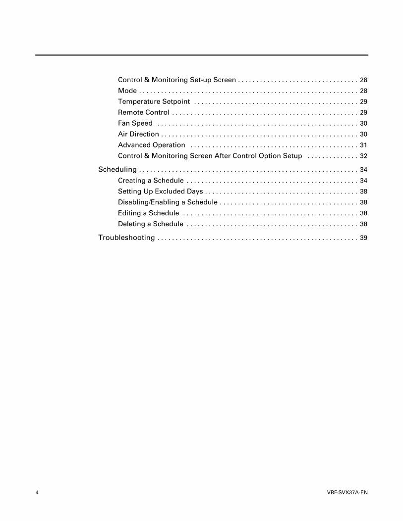
Dimensions
Mounting plate
6.7 (170)
Unit: inch (mm)
6.4 (163)
1.5 (38)
5.6 (141)
8.1 (205)
VRF-SVX37A-EN 7

Product Overview
System Architecture
08:23 PM
VRF System Touchscreen
Control & Monitoring
Schedule Setting
08:23 PM
VRF System Touchscreen
Control & Monitoring
Schedule Setting
InternetTCP/IP
VRF System Controller
VRF System Touchscreen
VRF System Touchscreen
Indoor units
Outdoor unitsR1, R2
F1, F2
Central On/Off Control
Central On/Off Control
8 VRF-SVX37A-EN

Installation
Installation
Mounting the Unit and Connecting Cables
The touchscreen should be mounted to a wall for convenience and to reduce the possibility of damage.
1. Attach the mounting plate to the wall using the four provided screws. Tighten the screws to 0.89–1.1 ft-lb (1.2–1.5 N-m).
2. Connect the power cable to the power terminal on the back of the touchscreen.
3. Arrange the cables as shown, either through the bottom or the back of the touchscreen.
WARNING
Hazardous Voltage!
Disconnect all electric power, including remote disconnects before servicing. Follow proper lockout/tagout procedures to ensure the power can not be inadvertently energized. Failure to disconnect power before servicing could result in death or serious injury.
Cables exiting through bottom Cables exiting through the back
Power cable
Communication cable
Cable ties
VRF-SVX37A-EN 9
Installation
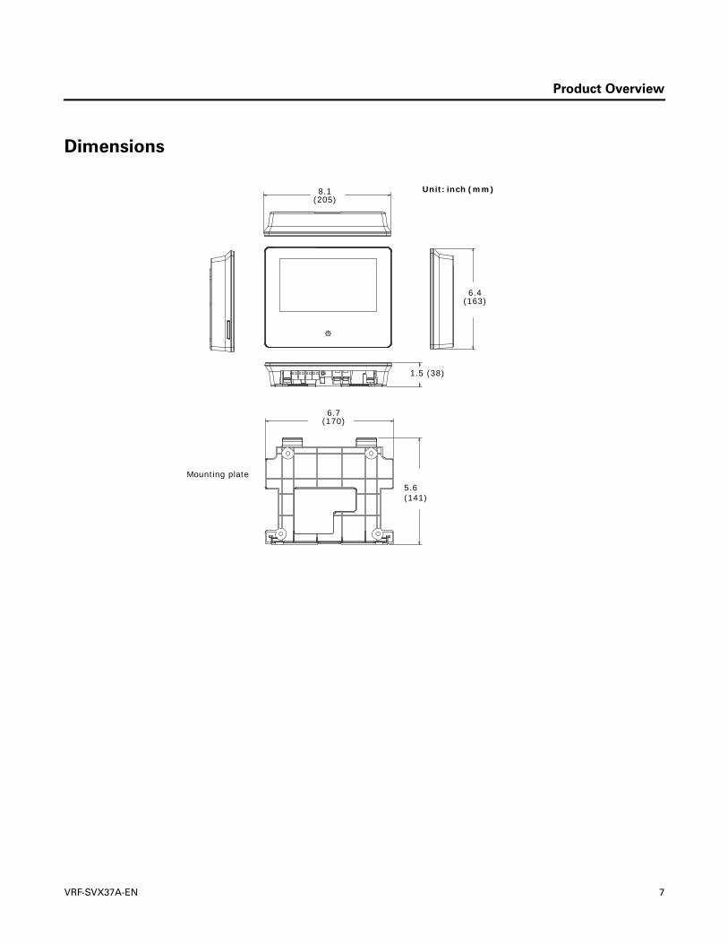
4. Connect the communication cables firmly, within rated torque range, to the RS-485 communication terminal (COM+, COM–) on the back of the touchscreen as described in the following illustrations.
• For higher-level control including systems with multiple outdoor units, connect COM+ to R1 and COM- on R2 on the outdoor unit control board (refer also to “System Architecture,“ p. 8):
• For single-system communication (main system communication line), connect COM+ to F1 and COM- to F2 on the indoor unit control board (refer also to “System Architecture,“ p. 8):
5. Hang the top of the touchscreen from the mounting plate as shown in the illustration. Attach the touchscreen to the hooks on the bottom of the installation plate, making sure that the touchscreen is securely attached.
F1 F2 R1 R2
COM+ –OF1 OF2
OUTDOOR UNIT CONTROL BOARD
TOUCHSCREEN
F1 F2
COM+ –
INDOOR UNIT CONTROL BOARD
TOUCHSCREEN
Hooks
10 VRF-SVX37A-EN
Installation
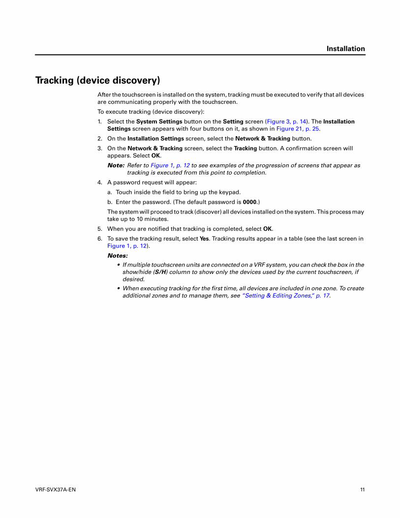
Tracking (device discovery)
After the touchscreen is installed on the system, tracking must be executed to verify that all devices are communicating properly with the touchscreen.
To execute tracking (device discovery):
1. Select the System Settings button on the Setting screen (Figure 3, p. 14). The Installation
Settings screen appears with four buttons on it, as shown in Figure 21, p. 25.
2. On the Installation Settings screen, select the Network & Tracking button.
3. On the Network & Tracking screen, select the Tracking button. A confirmation screen will appears. Select OK.
Note: Refer to Figure 1, p. 12 to see examples of the progression of screens that appear as tracking is executed from this point to completion.
4. A password request will appear:
a. Touch inside the field to bring up the keypad.
b. Enter the password. (The default password is 0000.)
The system will proceed to track (discover) all devices installed on the system. This process may take up to 10 minutes.
5. When you are notified that tracking is completed, select OK.
6. To save the tracking result, select Yes. Tracking results appear in a table (see the last screen in Figure 1, p. 12).
Notes:
• If multiple touchscreen units are connected on a VRF system, you can check the box in the show/hide (S/H) column to show only the devices used by the current touchscreen, if desired.
• When executing tracking for the first time, all devices are included in one zone. To create additional zones and to manage them, see “Setting & Editing Zones,“ p. 17.
VRF-SVX37A-EN 11

Installation
Figure 1. Tracking procedure
12 VRF-SVX37A-EN

Basic Operation
Basic Operation
Touchscreen Guidelines
The touchscreen registers the downward pressure of a touch. Light, quick, yet deliberate presses are most effective. Touching with more pressure has no effect.
If you apply and hold pressure at more than one point, the touchscreen registers only the first touch. For example, if you press a finger on an area of the screen that is not touch sensitive, pressing a sensitive area with another finger will not register.
Holding on to the screen with your hand can cause unintended navigation, such as from thumb or palm pressure.
Buttons
Home button
Returns to return to the home screen from any other screen.
Back button
Cancels a setting on any screen.
LCD On/Off Button
When pressed, the power button on the front of the touchscreen (Figure 2) powers the touchscreen On or Off.
The LCD On/Off button light is:• Blue, to indicate that at least one indoor unit in is turned On.• Red, to indicate that an indoor unit is experiencing an error.
Figure 2. Home screen and power button
Screen Protection Mode
If there is no input to the VRF System Touchscreen after a defined period of time, the screen will change to screen protection mode. In this mode, the backlight is Off.• To end screen protection mode, press the LCD On/Off button.• While in screen protection mode, the touchscreen continues operating.
LCD On/Off button
08:23 PM
VRF System Touchscreen
Control & Monitoring
Schedule Setting
VRF-SVX37A-EN 13

Settings
Settings
To navigate to the Setting screen, select the Setting button on the Home page. The Setting screen appears with three button on it, as shown in Figure 3.
Figure 3. Setting screen
System Settings
To view and change system settings, select the System Settings button that is found on the Setting page (Figure 3). The System Settings screen appears with nine buttons on it, as shown in Figure 4.
Figure 4. System Settings screen
Lock
From the System Settings screen, select the Lock button. Three types of lock settings are available:
Screen Lock: If the screen is locked, a password is required to access the menu if the backlight turns off due to extended inactivity of the touchscreen.
Operation Panel Lock: This screen contains specific control settings which, if locked, prevent unauthorized users from changing them.
Menu Lock: Three menus can be locked: control, schedule, and setting. If locked, the menu will appear with a lock icon. A password must be entered to access a locked menu.
14 VRF-SVX37A-EN

Settings
Password
From the System Settings screen, select the Password button. The Password screen allows you to set or change a password to protect the touchscreen from unauthorized use.
• Touching inside the field brings up the keypad.
• The default password is 0000.
Indoor Unit Options
From the System Settings screen, select the Indoor Unit Options button. This screen contains three indoor unit options, as follows:
• Auto Mode: The default setting is Enabled. If this option is set to Disabled, Auto cannot be selected as the operating mode for any indoor unit in the system (see “Mode,“ p. 28).
• Temperature control step: The default setting for the temperature increment that is displayed is 1.0. The available settings are 1.0, 0.5, and 0.1. However, if temperature display units is set to Fahrenheit, the temperature control unit is 1.0.
• Temperature display units: The default setting is Fahrenheit. The available settings are Celsius and Fahrenheit.
Language
From the System Settings screen, select the Language button. The Language Setting screen allows you to change the language shown on the touchscreen. The touchscreen supports Dutch, English, French, German, Greek, Hungarian, Italian, Korean, Polish, Portuguese, Slovak, and Spanish.
Time & Date Settings
From the System Settings screen, select the Time & Date Settings button. The Date and time screen (Figure 5) allows you to set up the current date and time and to select additional options as listed.
Figure 5. Date and time screen
• The 12-hour time format is the default. To change it to the 24-hour format, select the 24-hour
format check box (Figure 5).
• Select the Select a time-zone button (Figure 5). Set the time zone of the selected country/area. Daylight savings time is automatically applied. When daylight savings time is active, the clock icon at the upper right corner of the screen appears with the sun behind it.
• Select the Date format button. From the Date & Time Format screen you can choose the date format, the day the week begins (Sunday or Monday), and you can select/deselect the 24-hour format (Figure 6, p. 16).
VRF-SVX37A-EN 15

Settings
Note: If you enter the date and time incorrectly, the schedule will not function properly.
Figure 6. Date & Time Format screen
Screen Settings
From the System Settings screen, select the Screen Settings button. The Screen Settings screen (see Figure 7) allows you to modify the appearance of the screen as described:
• Brightness: Select a location on the bar to adjust the brightness of the LCD screen from 0–100%.
• Backlight timeout: Select a location on the bar to adjust the time that elapses before the backlight turns off (1–10 minutes).
Figure 7. Screen Settings screen
16 VRF-SVX37A-EN

Settings
Setting & Editing Zones
The touchscreen controls indoor units by zones. Zones enable individual indoor units with similar control characteristics to be controlled as a group for convenience.
From the System Settings screen, select the Setting & Editing Zone button. The Setting & Editing
Zone screen appears, initially, with a single zone containing all of the indoor units (Figure 8).
Figure 8. Setting & Editing Zone: Initial screen with a single zone containing all indoor units
The zone list screen contains a row of buttons at the bottom that are used to manage zones. Table 1 explains the purpose of the buttons.
Viewing Individual Units
To view the individual indoor units that are in a zone:
1. Select the zone. It will appear highlighted and the Into (Zone) button will become enabled.
2. Then select the Into (Zone) button. A screen appears containing an icon for each indoor unit that has been tracked (see Figure 9).
If more than 12 indoor units exist, more pages are created as necessary until all indoor units are represented on a page. Page numbers appear at the bottom center of each page of indoor units. Figure 9 shows a zone with two pages. Page 1 is currently in view. To view another page, select the desired page number.
Table 1. Zone management buttons
Icon Button name Purpose
Creating zone Creates a zone. See “Creating a Zone,“ p. 18
Into (Zone) Shows the screen that contains all of the indoor units in that zone. See Figure 9, p. 18
Delete zone Deletes the zone a user has selected. If the zone contains a device, the zone cannot be deleted.
Change iconAllows you to choose an icon from a screen containing series of descriptive icon choices. Select an appropriate icon according to the purpose of the room/area and select OK. Refer to Figure 32, p. 32, to see an example of a zone list that has been updated with icons.
Rename Allows you to rename a zone to a name that is more descriptive name than the default name. Select the name field, type a new name, and select OK.
Save Saves settings that were applied at this screen.
VRF-SVX37A-EN 17

Settings
Figure 9. Setting & Editing Zone: Initial screen shown all indoor units in one zone
The screen at the unit level contains a row of buttons at the bottom that are used to manage units. Table 2 explains the purpose of the buttons.
Creating a Zone
The first zone is created automatically. To create additional zones (the maximum is 12), select the Create zone button at the bottom of the screen. Figure 10 shows a page with a total of 12 zones on it.
Figure 10. Setting & Editing Zone: 12 zones
Table 2. Unit management buttons
Icon Button name Purpose
Delete page Deletes a page that does not contain units. (You cannot delete a page that contains units.)
Move zone Moves a selected unit to a different zone.
Move page Moves a selected unit to another page.
BindGroups units so that they are controlled as a single unit. The last unit selected to belong to the group will be the unit that is displayed on the screen. Refer to “Setting up Group Control,“ p. 22.
Unbind Separates units that have been grouped.
Rename Renames a unit. (Refer to “Renaming a Zone,“ p. 22.)
Save Saves settings that were applied at this screen.
The “1” is highlighted to show that page 1 is currently in view.
18 VRF-SVX37A-EN

Settings
Moving Units Into a New Zone
Note: Unless a zone has been renamed, it will appear as Zone Name#1, Zone Name#2, and so on. A selected zone will appear highlighted, as shown in Figure 11.
To move indoor units into a new zone:
1. Select the zone that you want to move an indoor unit into. The zone will appear highlighted as in Figure 11.
Figure 11. Setting & Editing Zone: Zone selected
2. Select the Into (Zone) button at the bottom left of the screen. A new screen appears (Figure 12) containing all of the indoor units in that zone.
Figure 12. Setting & Editing Zone: Indoor units
3. Select the unit(s) that you want to move into the selected zone. (In the example in Figure 12, the two indoor units that are highlighted have been selected.)
4. Select the Move zone button. A screen appears containing the zone lists and the heading “Select a Zone to go to” (as shown in Figure 13).
5. On this screen, select the zone you want to move the unit(s) into. The selected zone will appear highlighted (as shown in Figure 13).
You can view the indoor units in a different zone by selecting this arrow.
VRF-SVX37A-EN 19

Settings
Figure 13. Setting & Editing Zone: Indoor units
6. Select OK. The screen shown in Figure 13 will close. The screen that the units were moved from is in view again (Figure 14).
Figure 14. Setting & Editing Zone: Indoor units
7. To confirm that the action was performed correctly:
a. Confirm that the selected units no longer appear in the zone list from which they were moved (see Figure 14).
b. Select the back button ( ).
c. Notice that Zone Name#3, which previously had 0 units, now shows a count of 2 units.
20 VRF-SVX37A-EN

Settings
d. Select the Into (Zone) button to see the two new units that were moved into this zone.
8. Select the Save button to save changes.
Moving Units to a Different Page
To move units to a different page within a zone containing multiple pages, follow these instructions:
1. View the page with the units that you want to move (see “Viewing Individual Units,“ p. 17).
2. Select the “N” on the circle to the right of the page numbers at the bottom of the page. A new page appears. Note the new highlighted number 6 at the bottom of the new page (see Figure 15).
Figure 15. Creating a new page
3. Return to the page containing the units you want to move. On that page, select the units you want to move. Then select the Move page button (see Figure 16).
4. On the new screen containing the page numbers for the zone, select you page number you want to move the units to (see Figure 16).
Note: If a page is full (containing 12 units), it cannot be selected.
VRF-SVX37A-EN 21

Settings
Figure 16. Selecting and moving units to a new page
5. To confirm that the action was performed correctly, view the page that previously contained the selected units to ensure that they are no longer there and/or view the new page to ensure that the selected units are there.
6. Select the Save button to save changes.
Setting up Group Control
Indoor units can be controlled as a single unit when they are grouped. To group indoor units, they must in the same zone and on the same page. (For information about these procedures, see “Moving Units Into a New Zone,“ p. 19 and “Moving Units to a Different Page,“ p. 21.)
To group indoor units:
1. View the page containing the units you want to group (see “Viewing Individual Units,“ p. 17).
2. Select the units that you want to group.
3. Select the Bind button ( ). The selected indoor units are now in a group, as shown in the right screen of Figure 17. The last unit selected to belong to the group is displayed on the screen to represent the group. The number in the top right corner of the indoor unit icon indicates that number of units in the group.
4. Select the Save button.
Figure 17. Setting up group control
Renaming a Zone
Zones can renamed for easy identification.
To rename a zone:
+04
22 VRF-SVX37A-EN

Settings
1. Select the zone that you want to rename. The zone button will appear highlighted.
2. Select the Rename button. The current name will appear in a field (Figure 18).
Figure 18. Setting & Editing Zone screen: Current zone name
3. Select the current name and a keyboard will appear (Figure 19).
Figure 19. Setting & Editing Zone screen: Renaming the zone
4. Use the keyboard to enter a new zone name.
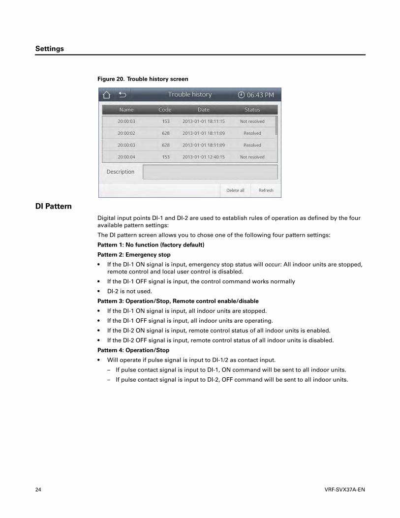
Trouble History
Trouble history contains stored information about errors that have occurred in the system. Figure 20 shows an example.
VRF-SVX37A-EN 23
Settings
Figure 20. Trouble history screen
DI Pattern
Digital input points DI-1 and DI-2 are used to establish rules of operation as defined by the four available pattern settings:
The DI pattern screen allows you to chose one of the following four pattern settings:
Pattern 1: No function (factory default)
Pattern 2: Emergency stop
• If the DI-1 ON signal is input, emergency stop status will occur: All indoor units are stopped, remote control and local user control is disabled.
• If the DI-1 OFF signal is input, the control command works normally
• DI-2 is not used.
Pattern 3: Operation/Stop, Remote control enable/disable
• If the DI-1 ON signal is input, all indoor units are stopped.
• If the DI-1 OFF signal is input, all indoor units are operating.
• If the DI-2 ON signal is input, remote control status of all indoor units is enabled.
• If the DI-2 OFF signal is input, remote control status of all indoor units is disabled.
Pattern 4: Operation/Stop
• Will operate if pulse signal is input to DI-1/2 as contact input.
– If pulse contact signal is input to DI-1, ON command will be sent to all indoor units.
– If pulse contact signal is input to DI-2, OFF command will be sent to all indoor units.
24 VRF-SVX37A-EN
Settings
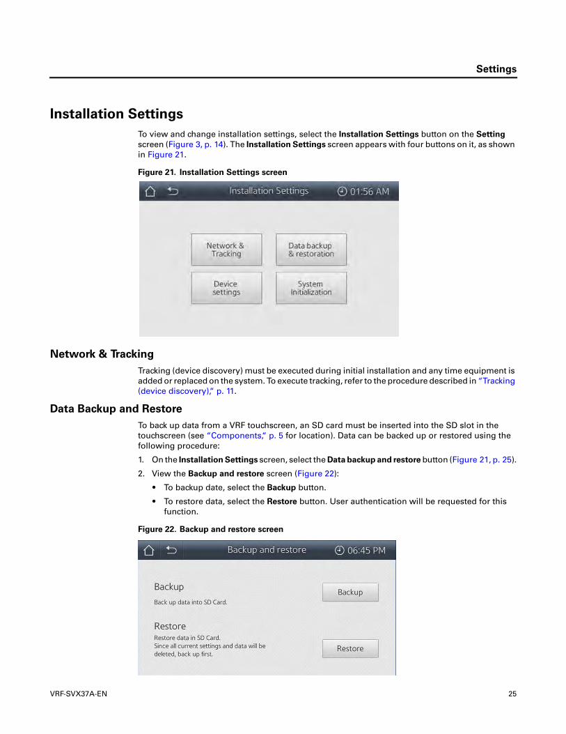
Installation Settings
To view and change installation settings, select the Installation Settings button on the Setting screen (Figure 3, p. 14). The Installation Settings screen appears with four buttons on it, as shown in Figure 21.
Figure 21. Installation Settings screen
Network & Tracking
Tracking (device discovery) must be executed during initial installation and any time equipment is added or replaced on the system. To execute tracking, refer to the procedure described in “Tracking (device discovery),“ p. 11.
Data Backup and Restore
To back up data from a VRF touchscreen, an SD card must be inserted into the SD slot in the touchscreen (see “Components,“ p. 5 for location). Data can be backed up or restored using the following procedure:
1. On the Installation Settings screen, select the Data backup and restore button (Figure 21, p. 25).
2. View the Backup and restore screen (Figure 22):
• To backup date, select the Backup button.
• To restore data, select the Restore button. User authentication will be requested for this function.
Figure 22. Backup and restore screen
VRF-SVX37A-EN 25

Settings
Device Settings
To view the Device Settings screen:
1. On the Installation Settings screen (Figure 21), select the Device settings button. The Device settings screen appears as shown in Figure 23.
Figure 23. Device Settings screen
2. Change settings as desired:
• Mode: Reserved for future use.
• Network: Reserved for future use.
• Control level: Select either Remote control or On/Off control. Relevant to systems that have the touchscreen, remote control, and On/Off Control all installed on them.
– Remote control: Provides the ability to control the use a remote control from both the indoor unit and the On/Off Control.
– On/Off control: Restricts the ability to control the use of a remote control to the touchscreen.
• Address: Allows manual communication address setting.
• Auto addressing: If the box is checked, addressing of the indoor units is automatic. Manual address setting is disabled.
3. Select the Save button.
System Initialization
To initialize system settings:
1. On the Installation Settings screen (Figure 21), select the System Initialization button.
2. Select the Initialize button.
Device Information
To view copyright and software version information, select the Device Information button that is found on the Setting page (Figure 3, p. 14). The Device Information screen appears.
To review the licensing information, select the Opensource Info button this page. Then select OK.
26 VRF-SVX37A-EN

Control and Monitoring
Control and Monitoring
The touchscreen allows control and monitoring by zone. All indoor units are initially contained in one zone. To create additional zones and move units to different zones, see “Setting & Editing Zones,“ p. 17.
On the home screen, select the Control & Monitoring button. The zone list will appear. Figure 24 shows an example with two zones.
Figure 24. Control & Monitoring screen prior to control option setup
Control set-up for individual zones: To set up or view control options for a selected zone:
1. Select the desired zone (screen #1) The indoor unit list will appear (screen #2).
2. On screen #2, select the desired unit(s), then select the Control button. The All Control screen will appear (screen #3). Settings made on this screen apply to all selected zones.
Control set-up for all zones: To set up control options for all zones simultaneously, select the Control All button on screen #1. The All Control screen will appear (screen #3). Settings made on this screen apply to all zones.
• Turn All Off button: Select this button to turn off operation of indoor units in all zones.
• Legend button: Select this button to view the meaning of the icons and colors used on the touchscreen.
#1 #2 #3
VRF-SVX37A-EN 27
Control and Monitoring
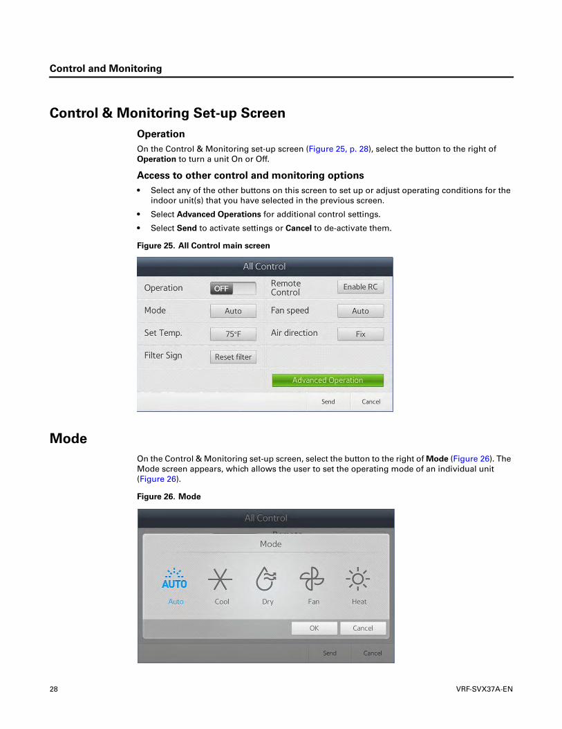
Control & Monitoring Set-up Screen
Operation
On the Control & Monitoring set-up screen (Figure 25, p. 28), select the button to the right of Operation to turn a unit On or Off.
Access to other control and monitoring options
• Select any of the other buttons on this screen to set up or adjust operating conditions for the indoor unit(s) that you have selected in the previous screen.
• Select Advanced Operations for additional control settings.
• Select Send to activate settings or Cancel to de-activate them.
Figure 25. All Control main screen
Mode
On the Control & Monitoring set-up screen, select the button to the right of Mode (Figure 26). The Mode screen appears, which allows the user to set the operating mode of an individual unit (Figure 26).
Figure 26. Mode
28 VRF-SVX37A-EN

Control and Monitoring
1. Select the icon that represents the desired operating mode.
2. Select OK to store the setting or Cancel to erase it. The selected mode is highlighted in blue.
3. Select Send to activate the setting or Cancel to de-activate it.
Temperature Setpoint
On the Control & Monitoring set-up screen, select the button to the right of Temp. Set (Figure 25, p. 28). The Set Temp. screen appears, which allows the user to set the desired indoor unit temperature setpoint (see Figure 27).
Figure 27. Temperature setpoint
1. Select the right/left arrow to scroll until the desired temperature appears in the middle of the screen, as in the Figure 27 example.
2. Select OK to store the setting or Cancel to erase it.
3. Select Send to activate the setting or Cancel to de-activate it.
Remote Control
On the Control & Monitoring set-up screen, select the button to the right of Remote Control
(Figure 25, p. 28). The Remote Control screen appears (Figure 28), which allows the user to set the desired indoor unit remote control level to one of the following:
• Enable RC allows control of the indoor unit by use of a wired or wireless remote controller or by use of the control panel on each indoor unit.
• Disable RC restricts control of the indoor unit by wired or wireless remote controller or by use of the control panel on each indoor unit.
• Cond. RC applies conditions on remote control use: If the indoor unit is powered on by the touchscreen, full control of the indoor unit is available using a wired/wireless remote control or an indoor unit panel. If the indoor unit is powered off by the touchscreen, the indoor unit cannot be powered On by a wired/wireless remote control or an indoor unit panel.
VRF-SVX37A-EN 29

Control and Monitoring
Figure 28. Remote control
1. Select the desired remote control setting.
2. Select OK to store the setting or Cancel to erase it. The selected setting is highlighted in blue.
3. Select Send to activate the setting or Cancel to de-activate it.
Fan Speed
On the Control & Monitoring set-up screen, select the button to the right of Fan speed. (Figure 26). The Fan speed screen appears (Figure 29), which allows the user to set the fan speed—Auto, Low, Mid, High—for an individual indoor unit.
Figure 29. Fan speed
1. Select the icon that represents the desired fan speed.
2. Select OK to store the setting or Cancel to erase it. The selected setting is highlighted in blue.
3. Select Send to activate the setting or Cancel to de-activate it.
Air Direction
On the Control & Monitoring set-up screen, select the button to the right of Air direction. (Figure 26). The Air direction screen appears (Figure 30), which allows the user to set the fan blade direction to vertical or horizontal for indoor units with adjustable fan blades.
30 VRF-SVX37A-EN

Control and Monitoring
Figure 30. Air direction
1. Select the icon that represents that desired fan blade direction.
2. Select OK to store the setting or Cancel to erase it. The selected mode is highlighted in blue.
3. Select Send to activate the setting or Cancel to de-activate it.
Advanced Operation
On the Control & Monitoring set-up screen, select the Advanced Operation button (Figure 25, p. 28). The Advanced Operation screen appears (Figure 31), which allows the user to set the following control options:
• Motion detection: Available only as an accessory on mini 4-way cassette indoor units.
• SPI: This feature is not available.
• Operation mode limit: Allows an indoor unit to be limited to cooling-only operation, heating-only operation, or without limits (“none”), which will allow either heating and cooling as required.
• Cool lower limit: Allows a minimum cooling limit to be set for a particular zone.
• Heat upper limit: Allows a maximum heating limit to be set for a particular zone.
Figure 31. Advanced operation
1. Select the button that represents that desired setting.
2. Select OK to store the setting or Cancel to erase it.
3. Select Send to activate the setting or Cancel to de-activate it.
VRF-SVX37A-EN 31

Control and Monitoring
Control & Monitoring Screen After Control Option Setup
Figure 32 is an example of the Control & Monitoring screen after indoor unit control options have been set up. Each zone appears with a name, the total indoor units in the zone, and the number of schedules associated with the zone. (To set up schedules, see “Scheduling,“ p. 34.)
Figure 32. Control & Monitoring screen: Zone list after control option setup
Select a zone button in the Zone List and to view the individual indoor units with their settings displayed (Figure 33).
Figure 33. Control & Monitoring screen: Indoor unit list in selected zone
For indoor units that have been grouped (see “Setting up Group Control,“ p. 22), the indoor unit that is displayed to represent the group is the first one selected to join the group. The number of units in the group appears in the upper right corner, as shown in Figure 34.
32 VRF-SVX37A-EN

Control and Monitoring
Figure 34. Control & Monitoring screen: Grouped indoor units
VRF-SVX37A-EN 33

Scheduling
Scheduling
The VRF System touchscreen uses schedules to control indoor unit operation. To create and manage schedules for connected indoor units, follow the procedures in this section.
• A maximum of 10 schedules per week can be set.
• A single schedule can contain a maximum of 10 events.
• Days can be excluded from the schedule.
On the home screen, select the Schedule button. If no schedules have been created, the screen will be blank. One schedule has been set up in the example shown in Figure 35.
Figure 35. Schedule screen
Creating a Schedule
1. On the Schedule screen, select New. The Create schedule screen will appear (Figure 36).
Figure 36. Create schedule screen
2. Select the Name field and enter a unique name for the schedule.
34 VRF-SVX37A-EN

Scheduling
3. Select the plus sign in the Indoor unit field to open the Add Indoor Unit screen. Figure 37 shows an example of this screen.
Figure 37. Add Indoor Unit screen, zone list
4. From the zone list, select the zone containing the units that you want to associate with the schedule. Select OK. The indoor units that are in the selected zone appear as a list (see Figure 38).
Figure 38. Add Indoor Unit screen, indoor unit list
5. From the indoor unit list, select the check mark on the indoor units that you want to associate with the schedule, or select the Select all button.
Note: To disassociate indoor units from a schedule, select the Deselect button.
6. Select the Add button. The Schedule screen appears showing the quantity of indoor units, in the Indoor unit field, that you selected in the previous screen to associate with the schedule.
Note: To delete an event, select Delete event.
VRF-SVX37A-EN 35

Scheduling
Figure 39. Create schedule screen, with indoor units associated
7. In the Schedule field, select the days of the week that you want the schedule to affect.
8. Select the Create Event button. The Create a Schedule Event screen will appear (Figure 40).
Figure 40. Create a Schedule Event screen
9. Establish the operating conditions of the indoor units that are to be controlled by the schedule:
• Time of operation: Select “OFF” and time to turn off; select “ON” and time to turn on.
• Select mode of operation.
• Set desired temperature for the active period.
• Select remote control level. (For more information, see “Remote Control,“ p. 29.) Select OK.
• ERV and DHW settings: Inactive. For future use.
10. Select OK. The Create schedule screen will appear with the scheduled events listed in the Events field (see Figure 41).
36 VRF-SVX37A-EN
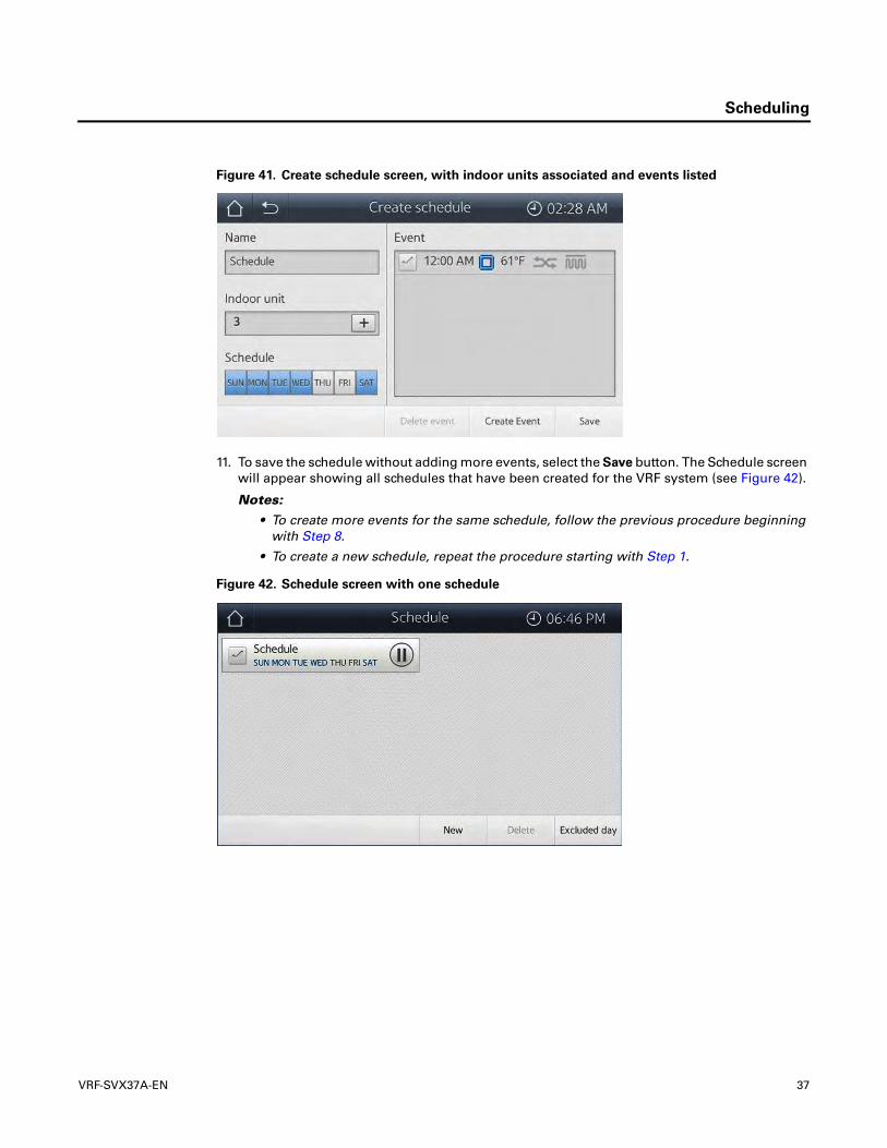
Scheduling
Figure 41. Create schedule screen, with indoor units associated and events listed
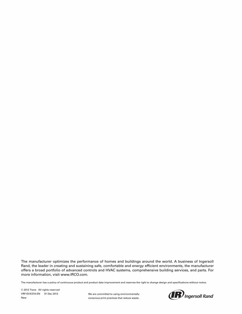
11. To save the schedule without adding more events, select the Save button. The Schedule screen will appear showing all schedules that have been created for the VRF system (see Figure 42).
Notes:
• To create more events for the same schedule, follow the previous procedure beginning with Step 8.
• To create a new schedule, repeat the procedure starting with Step 1.
Figure 42. Schedule screen with one schedule
VRF-SVX37A-EN 37

Scheduling
Setting Up Excluded Days
1. On the Schedule screen (see Figure 42, p. 37), select the Excluded day button. The following screen (Figure 43) appears.
Figure 43. Excluded screen
2. Select the day on the calendar that is to be excluded.
Note: For convenience, you can select Sun and/or Sat buttons to exclude all Saturdays or all Sundays in the month.
3. Select the Add button to add the selected day to the schedule. The day will appear on the right side of the screen.
Note: To delete excluded days from the schedule, select the Delete button.
4. Select Save.
Disabling/Enabling a Schedule
On the Schedule screen (see Figure 42) disable/enable a schedule by touching the stop/go icon to the right of the schedule.
Editing a Schedule
1. On the Schedule screen (see Figure 42), ensure that the schedule that you want to edit is enabled.
2. Select the schedule you want to edit. The Create Schedule screen that contains all of the schedule settings will appear (see Figure 41 as an example).
3. Make changes to the parameters and details as needed.
4. Select Save.
Deleting a Schedule
1. On the Schedule screen (see Figure 42), ensure that the schedule that you want to delete is enabled.
2. Select the check mark to select the schedule that you want to delete.
3. Press Delete.
38 VRF-SVX37A-EN

Troubleshooting
Troubleshooting
Before reporting on a product malfunction, please review the troubleshooting table.
Problem Check Solution
Screen of LCD does not show anything
Is power supplied correctly? After checking the power supply connection, plug in the product again.
Is the product in screen-protection mode?
When there is no input by a user for a certain time, the LCD will be turned off automatically. Turn the LCD screen on with LCD ON/OFF button.
Indoor unit control does not work.
Is the communication cable unplugged?
Check the connection status of communication cable between an indoor unit and outdoor unit.
Desired temperature does not increase or decrease.
Has Heat upper limit or Cool lower limit been set?
When the temperature limit is set, a user can adjust the desired temperature within the range of the temperature limit.
Remote controller does not work.
Is the use of the remote controller restricted?
Check the remote control setting level: If it is set as Disable RC, you cannot control the indoor unit with wireless or wired remote controller.
Schedule control does not work with the set time.
Is the set time of product different from current time?
Set the current time again: “Time & Date Settings,“ p. 15
Modifying a schedule is not available.
Is the schedule in operation? Modification of a schedule is available only in stop status.
VRF-SVX37A-EN 39
The manufacturer optimizes the performance of homes and buildings around the world. A business of Ingersoll Rand, the leader in creating and sustaining safe, comfortable and energy efficient environments, the manufactureroffers a broad portfolio of advanced controls and HVAC systems, comprehensive building services, and parts. For more information, visit www.IRCO.com.
The manufacturer has a policy of continuous product and product data improvement and reserves the right to change design and specifications without notice.
We are committed to using environmentally
conscious print practices that reduce waste.
© 2013 Trane All rights reserved
VRF-SVX37A-EN 01 Dec 2013
New