Les mondes arabes et la question palestinienne: appareils ...
Installation and operation manualSplit system air conditioners English
Installation and operationmanual
Split system air conditioners
FCAG35AVEB FCAG50AVEB FCAG60AVEB FCAG71AVEB FCAG100AVEB FCAG125AVEB FCAG140AVEB
3P480520-2A
CE - DECLARATION-OF-CONFORMITY CE - DECLARACION-DE-CONFORMIDAD CE - DECLARAÇÃO-DE-CONFORMIDADE CE - ERKLÆRING OM-SAMSVAR CE - IZJAVA-O-USKLAĐENOSTI CE - IZJAVA O SKLADNOSTI CE - ATITIKTIES-DEKLARACIJACE - KONFORMITÄTSERKLÄRUNG CE - DICHIARAZIONE-DI-CONFORMITA CE - ЗАЯВЛЕНИЕ-О-СООТВЕТСТВИИ CE - ILMOITUS-YHDENMUKAISUUDESTA CE - MEGFELELŐSÉGI-NYILATKOZAT CE - VASTAVUSDEKLARATSIOON CE - ATBILSTĪBAS-DEKLARĀCIJACE - DECLARATION-DE-CONFORMITE CE - ΔHΛΩΣΗ ΣΥΜΜΟΡΦΩΣΗΣ CE -
OVERENSSTEMMELSESERKLÆRINGCE - PROHLÁŠENÍ-O-SHODĚ CE - DEKLARACJA-ZGODNOŚCI CE - ДЕКЛАРАЦИЯ-ЗА-СЪОТВЕТСТВИЕ CE - VYHLÁSENIE-ZHODY
CE - CONFORMITEITSVERKLARING CE - FÖRSÄKRAN-OM-ÖVERENSTÄMMELSE
CE - DECLARAŢIE-DE-CONFORMITATE CE - UYGUNLUK-BEYANI
01
02
03 04
05
06 07 08
declares under its sole responsibility that the air conditioning models to which this declarationrelates:erklärt auf seine alleinige Verantwortung daß die Modelle der Klimageräte für die diese Erklärungbestimmt ist:déclare sous sa seule responsabilité que les appareils d'air conditionné visés par la présentedéclaration:verklaart hierbij op eigen exclusieve verantwoordelijkheid dat de airconditioning units waarop dezeverklaring betrekking heeft:declara baja su única responsabilidad que los modelos de aire acondicionado a los cuales hacereferencia la declaración:dichiara sotto sua responsabilità che i condizionatori modello a cui è riferita questa dichiarazione:δηλώνει με αποκλειστική της ευθύνη ότι τα μοντέλα των κλιματιστικών συσκευών στα οποίααναφέρεται η παρούσα δήλωση:declara sob sua exclusiva responsabilidade que os modelos de ar condicionado a que estadeclaração se refere:
09 10 11 12 13 14 15 16
заявляет, исключительно под свою ответственность, что модели кондиционеров воздуха, ккоторым относится настоящее заявление:erklærer under eneansvar, at klimaanlægmodellerne, som denne deklaration vedrører:deklarerar i egenskap av huvudansvarig, att luftkonditioneringsmodellerna som berörs av dennadeklaration innebär att:erklærer et fullstendig ansvar for at de luftkondisjoneringsmodeller som berøres av dennedeklarasjon, innebærer at:ilmoittaa yksinomaan omalla vastuullaan, että tämän ilmoituksen tarkoittamat ilmastointilaitteidenmallit:prohlašuje ve své plné odpovědnosti, že modely klimatizace, k nimž se toto prohlášení vztahuje:izjavljuje pod isključivo vlastitom odgovornošću da su modeli klima uređaja na koje se ova izjavaodnosi:teljes felelőssége tudatában kijelenti, hogy a klímaberendezés modellek, melyekre e nyilatkozatvonatkozik:
17 18 19 20 21 22 23 24 25
deklaruje na własną i wyłączną odpowiedzialność, że modele klimatyzatorów, których dotyczyniniejsza deklaracja:declară pe proprie răspundere că aparatele de aer condiţionat la care se referă această declaraţie:z vso odgovornostjo izjavlja, da so modeli klimatskih naprav, na katere se izjava nanaša:kinnitab oma täielikul vastutusel, et käesoleva deklaratsiooni alla kuuluvad kliimaseadmete mudelid:декларира на своя отговорност, че моделите климатична инсталация, за които се отнася тазидекларация:visiška savo atsakomybe skelbia, kad oro kondicionavimo prietaisų modeliai, kuriems yra taikoma šideklaracija:ar pilnu atbildību apliecina, ka tālāk uzskaitīto modeļu gaisa kondicionētāji, uz kuriem attiecas šīdeklarācija:vyhlasuje na vlastnú zodpovednosť, že tieto klimatizačné modely, na ktoré sa vzťahuje totovyhlásenie:tamamen kendi sorumluluǧunda olmak üzere bu bildirinin ilgili olduǧu klima modellerinin aşaǧıdakigibi olduǧunu beyan eder:
0102
0304
05
0607
are in conformity with the following standard(s) or other normative document(s), provided that theseare used in accordance with our instructions:der/den folgenden Norm(en) oder einem anderen Normdokument oder -dokumenten entspricht/entsprechen, unter der Voraussetzung, daß sie gemäß unseren Anweisungen eingesetzt werden:sont conformes à la/aux norme(s) ou autre(s) document(s) normatif(s), pour autant qu'ils soient utilisésconformément à nos instructions:conform de volgende norm(en) of één of meer andere bindende documenten zijn, op voorwaarde datze worden gebruikt overeenkomstig onze instructies:están en conformidad con la(s) siguiente(s) norma(s) u otro(s) documento(s) normativo(s), siempreque sean utilizados de acuerdo con nuestras instrucciones:sono conformi al(i) seguente(i) standard(s) o altro(i) documento(i) a carattere normativo, a patto chevengano usati in conformità alle nostre istruzioni:είναι σύμφωνα με το(α) ακόλουθο(α) πρότυπο(α) ή άλλο έγγραφο(α) κανονισμών, υπό τηνπροϋπόθεση ότι χρησιμοποιούνταισύμφωνα με τις οδηγίες μας:
08
091011
12
131415
estão em conformidade com a(s) seguinte(s) norma(s) ou outro(s) documento(s) normativo(s), desdeque estes sejam utilizados deacordo com as nossas instruções:соответствуют следующим стандартам или другим нормативным документам, при условии ихиспользования согласно нашим инструкциям:overholder følgende standard(er) eller andet/andre retningsgivende dokument(er), forudsat at disseanvendes i henhold til vore instrukser:respektive utrustning är utförd i överensstämmelse med och följer följande standard(er) eller andranormgivande dokument, under förutsättning att användning sker i överensstämmelse med vårainstruktioner:respektive utstyr er i overensstemmelse med følgende standard(er) eller andre normgivendedokument(er), under forutssetning av at disse brukes i henhold til våre instrukser:vastaavat seuraavien standardien ja muiden ohjeellisten dokumenttien vaatimuksia edellyttäen, ettäniitä käytetään ohjeidemme mukaisesti:za předpokladu, že jsou využívány v souladu s našimi pokyny, odpovídají následujícím normám nebonormativním dokumentům:u skladu sa slijedećim standardom(ima) ili drugim normativnim dokumentom(ima), uz uvjet da se onikoriste u skladu s našim uputama:
161718
192021222324
25
megfelelnek az alábbi szabvány(ok)nak vagy egyéb irányadó dokumentum(ok)nak, ha azokat előírásszerint használják:spełniają wymogi następujących norm i innych dokumentów normalizacyjnych, pod warunkiem żeużywane są zgodnie z naszymi instrukcjami:sunt în conformitate cu următorul (următoarele) standard(e) sau alt(e) document(e) normativ(e), cucondiţia ca acestea să fie utilizate în conformitate cu instrucţiunile noastre:skladni z naslednjimi standardi in drugimi normativi, pod pogojem, da se uporabljajo v skladu z našiminavodili:on vastavuses järgmis(t)e standardi(te)ga või teiste normatiivsete dokumentidega, kui neid kasutataksevastavalt meie juhenditele:съответстват на следните стандарти или други нормативни документи, при условие, че сеизползват съгласно нашите инструкции:atitinka žemiau nurodytus standartus ir (arba) kitus norminius dokumentus su sąlyga, kad yranaudojami pagal mūsų nurodymus:tad, ja lietoti atbilstoši ražotāja norādījumiem, atbilst sekojošiem standartiem un citiem normatīviemdokumentiem:sú v zhode s nasledovnou(ými) normou(ami) alebo iným(i) normatívnym(i) dokumentom(ami), zapredpokladu, že sa používajú v súlade s našim návodom:ürünün, talimatlarımıza göre kullanılması koşuluyla aşağıdaki standartlar ve norm belirten belgelerleuyumludur:
010203040506070809
following the provisions of:gemäß den Vorschriften der:conformément aux stipulations des:overeenkomstig de bepalingen van:siguiendo las disposiciones de:secondo le prescrizioni per:με τήρηση των διατάξεων των:de acordo com o previsto em:в соответствии с положениями:
101112131415161718
under iagttagelse af bestemmelserne i:enligt villkoren i:gitt i henhold til bestemmelsene i:noudattaen määräyksiä:za dodržení ustanovení předpisu:prema odredbama:követi a(z):zgodnie z postanowieniami Dyrektyw:în urma prevederilor:
19202122232425
ob upoštevanju določb:vastavalt nõuetele:следвайки клаузите на:laikantis nuostatų, pateikiamų:ievērojot prasības, kas noteiktas:održiavajúc ustanovenia:bunun koşullarına uygun olarak:
010203040506070809
Directives, as amended.Direktiven, gemäß Änderung.Directives, telles que modifiées.Richtlijnen, zoals geamendeerd.Directivas, según lo enmendado.Direttive, come da modifica.Οδηγιών, όπως έχουν τροποποιηθεί.Directivas, conforme alteração em.Директив со всеми поправками.
1011121314151617
Direktiver, med senere ændringer.Direktiv, med företagna ändringar.Direktiver, med foretatte endringer.Direktiivejä, sellaisina kuin ne ovat muutettuina.v platném znění.Smjernice, kako je izmijenjeno.irányelv(ek) és módosításaik rendelkezéseit.z późniejszymi poprawkami.
1819202122232425
Directivelor, cu amendamentele respective.Direktive z vsemi spremembami.Direktiivid koos muudatustega.Директиви, с техните изменения.Direktyvose su papildymais.Direktīvās un to papildinājumos.Smernice, v platnom znení.Değiştirilmiş halleriyle Yönetmelikler.
01 Note*
02 Hinweis*
03 Remarque*
04 Bemerk*
05 Nota*
as set out in <A> and judgedpositively by <B> according to theCertificate <C>.wie in <A> aufgeführt und von <B>positivbeurteilt gemäß Zertifikat <C>.tel que défini dans <A> et évaluépositivement par <B> conformémentau Certificat <C>.zoals vermeld in <A> en positiefbeoordeeld door <B>overeenkomstig Certificaat <C>.como se establece en <A> y esvalorado positivamente por <B> deacuerdo con el Certificado <C>.
06 Nota*
07 Σημείωση*
08 Nota*
09 Примечание*
10 Bemærk*
delineato nel <A> e giudicatopositivamente da <B> secondo ilCertificato <C>.όπως καθορίζεται στο <A> και κρίνεταιθετικάαπό το <B> σύμφωνα με τοΠιστοποιητικό <C>.tal como estabelecido em <A> e com oparecer positivo de <B> de acordo como Certificado <C>.как указано в <A> и в соответствиис положительным решением <B>согласно Свидетельству <C>.som anført i <A> og positivt vurderet af<B> i henhold til Certifikat <C>.
11 Information*
12 Merk*
13 Huom*
14 Poznámka*
15 Napomena*
enligt <A> och godkänts av <B>enligt Certifikatet <C>.som det fremkommer i <A> oggjennom positiv bedømmelse av <B>ifølge Sertifikat <C>.jotka on esitetty asiakirjassa <A> jajotka <B>on hyväksynyt Sertifikaatin <C>mukaisesti.jak bylo uvedeno v <A> a pozitivnězjištěno<B> v souladu s osvědčením <C>.kako je izloženo u <A> i pozitivnoocijenjeno od strane <B> premaCertifikatu <C>.
16 Megjegyzés*
17 Uwaga*
18 Notă*
19 Opomba*
20 Märkus*
a(z) <A> alapján, a(z) <B> igazolta amegfelelést, a(z) <C> tanúsítványszerint.zgodnie z dokumentacją <A>,pozytywnąopinią <B> i Świadectwem <C>.aşa cum este stabilit în <A> şiapreciat pozitiv de <B> înconformitate cu Certificatul <C>.kot je določeno v <A> in odobreno sstrani <B> v skladus certifikatom <C>.nagu on näidatud dokumendis <A> jaheaks kiidetud <B> järgi vastavaltsertifikaadile <C>.
21 Забележка*
22 Pastaba*
23 Piezīmes*
24 Poznámka*
25 Not*
както е изложено в <A> и оцененоположително от <B> съгласноСертификата <C>.kaip nustatyta <A> ir kaip teigiamainuspręsta <B> pagal Sertifikatą <C>.kā norādīts <A> un atbilstoši <B>pozitīvajam vērtējumam saskaņā arsertifikātu <C>.ako bolo uvedené v <A> a pozitívnezistené <B> v súlade sosvedčením <C>.<A>’da belirtildiği gibi ve<C> Sertifikasına göre <B> tarafındanolumlu olarak değerlendirildiği gibi.
01**02**03**04**05**06**
DICz*** is authorised to compile the Technical Construction File.DICz*** hat die Berechtigung die Technische Konstruktionsaktezusammenzustellen.DICz*** est autorisé à compiler le Dossier de Construction Technique.DICz*** is bevoegd om het Technisch Constructiedossier samen testellen.DICz*** está autorizado a compilar el Archivo de Construcción Técnica.DICz*** è autorizzata a redigere il File Tecnico di Costruzione.
07**08**09**10**11**12**
Η DICz*** είναι εξουσιοδοτημένη να συντάξει τον Τεχνικό φάκελοκατασκευής.A DICz*** está autorizada a compilar a documentação técnica de fabrico.Компания DICz*** уполномочена составить Комплект техническойдокументации.DICz*** er autoriseret til at udarbejde de tekniske konstruktionsdata.DICz*** är bemyndigade att sammanställa den tekniska konstruktionsfilen.DICz*** har tillatelse til å kompilere den Tekniske konstruksjonsfilen.
13**14**15**16**17**18**
DICz*** on valtuutettu laatimaan Teknisen asiakirjan.Společnost DICz*** má oprávnění ke kompilaci souboru technickékonstrukce.DICz*** je ovlašten za izradu Datoteke o tehničkoj konstrukciji.A DICz*** jogosult a műszaki konstrukciós dokumentáció összeállítására.DICz*** ma upoważnienie do zbierania i opracowywania dokumentacjikonstrukcyjnej.DICz*** este autorizat să compileze Dosarul tehnic de construcţie.
19**20**21**22**23**24**25**
DICz*** je pooblaščen za sestavo datoteke s tehnično mapo.DICz*** on volitatud koostama tehnilist dokumentatsiooni.DICz*** е оторизирана да състави Акта за техническаконструкция.DICz*** yra įgaliota sudaryti šį techninės konstrukcijos failą.DICz*** ir autorizēts sastādīt tehnisko dokumentāciju.Spoločnosť DICz*** je oprávnená vytvoriť súbor technickejkonštrukcie.DICz*** Teknik Yapı Dosyasını derlemeye yetkilidir.
***DICz = Daikin Industries Czech Republic s.r.o.
Dai
kin
Indu
strie
s C
zech
Rep
ublic
s.r.
o.
FCA
G35
AVE
B, F
CA
G50
AVE
B, F
CA
G60
AVE
B, F
CA
G71
AVE
B, F
CA
G10
0AVE
B, F
CA
G12
5AVE
B, F
CA
G14
0AVE
B,
EN
6033
5-2-
40,
Mac
hine
ry 2
006/
42/E
CE
lect
rom
agne
tic C
ompa
tibili
ty 2
014/
30/E
ULo
w V
olta
ge 2
014/
35/E
U
** *
CE - D
ECLA
RATIO
N-OF-C
ONFO
RMITY
CE - D
ECLA
RACIO
N-DE-C
ONFO
RMIDA
DCE
- DEC
LARA
ÇÃO-
DE-CO
NFOR
MIDA
DECE
- ERK
LÆRIN
G OM-
SAMS
VAR
CE - I
ZJAV
A-O-US
KLAĐ
ENOS
TICE
- IZJ
AVA O
SKLA
DNOS
TICE
- ATIT
IKTIES
-DEKL
ARAC
IJACE
- KON
FORM
ITÄTS
ERKL
ÄRUN
GCE
- DICH
IARAZ
IONE-D
I-CON
FORM
ITACE
- ЗАЯ
ВЛЕН
ИЕ-О
-СООТ
ВЕТС
ТВИИ
CE - I
LMOIT
US-YH
DENM
UKAIS
UUDE
STA
CE - M
EGFE
LELŐ
SÉGI-
NYILA
TKOZ
ATCE
- VAS
TAVU
SDEK
LARA
TSIOO
NCE
- ATB
ILSTĪB
AS-DE
KLAR
ĀCIJA
CE - D
ECLA
RATIO
N-DE-C
ONFO
RMITE
CE - Δ
HΛΩΣ
Η ΣΥΜ
ΜΟΡΦ
ΩΣΗΣ
CE - O
VERE
NSST
EMME
LSES
ERKL
ÆRING
CE - P
ROHL
ÁŠEN
Í-O-SH
ODĚ
CE - D
EKLA
RACJ
A-ZGO
DNOŚ
CICE
- ДЕК
ЛАРА
ЦИЯ-З
А-СЪО
ТВЕТ
СТВИ
ЕCE
- VYH
LÁSE
NIE-ZH
ODY
CE - C
ONFO
RMITE
ITSVE
RKLA
RING
CE - F
ÖRSÄ
KRAN
-OM-
ÖVER
ENST
ÄMME
LSE
CE - D
ECLA
RAŢIE
-DE-CO
NFOR
MITA
TECE
- UYG
UNLU
K-BEY
ANI
01
02
03
04
05
06
07
08
decla
res un
der it
s sole
resp
onsib
ility th
at the
air c
ondit
ioning
mod
els to
which
this d
eclar
ation
relat
es:
erklär
t auf
seine
allein
ige Ve
rantwo
rtung
daß d
ie Mo
delle
der K
limag
eräte
für di
e dies
e Erkl
ärung
bestim
mt ist
:dé
clare
sous
sa se
ule re
spon
sabili
té qu
e les
appa
reils d
'air co
nditio
nné v
isés p
ar la
prése
nte dé
clarat
ion:
verkl
aart h
ierbij
op ei
gen e
xclus
ieve v
erantw
oorde
lijkhe
id da
t de a
ircon
dition
ing un
its wa
arop d
eze v
erklar
ing be
trekki
ng he
eft:
decla
ra ba
ja su
única
resp
onsa
bilida
d que
los m
odelo
s de a
ire ac
ondic
ionad
o a lo
s cua
les ha
ce re
feren
cia la
decla
ración
:dic
hiara
sotto
sua r
espo
nsab
ilità ch
e i co
ndizio
nator
i mod
ello a
cui è
riferi
ta qu
esta
dichia
razion
e:δη
λώνει
με απ
οκλει
στική
της ε
υθύν
η ότι τ
α μον
τέλα τ
ων κλ
ιματισ
τικών
συσκ
ευών σ
τα οπ
οία αν
αφέρε
ται η
παρο
ύσα δ
ήλωσ
η:de
clara
sob s
ua ex
clusiv
a res
pons
abilid
ade q
ue os
mod
elos d
e ar c
ondic
ionad
o a qu
e esta
decla
ração
se re
fere:
09
10
11
12
13
14
15
16
заявл
яет, и
сключ
итель
но по
д сво
ю отв
етстве
ннос
ть, чт
о мод
ели к
онди
цион
еров
возд
уха, к
котор
ым от
носи
тся на
стоящ
ее за
явле
ние:
erklæ
rer un
der e
nean
svar, a
t klim
aanlæ
gmod
ellerne
, som
denn
e dek
larati
on ve
drører
:de
klarer
ar i e
gens
kap a
v huv
udan
svarig
, att l
uftko
nditio
nerin
gsmo
deller
na so
m be
rörs a
v den
na de
klarat
ion in
nebä
r att:
erklæ
rer et
fullst
endig
ansva
r for a
t de l
uftko
ndisjo
nerin
gsmo
deller
som
berør
es av
denn
e dek
laras
jon, in
nebæ
rer at
:ilm
oittaa
yksin
omaa
n oma
lla va
stuulla
an, e
ttä tä
män i
lmoit
ukse
n tark
oittam
at ilm
astoi
ntilait
teide
n malli
t:pro
hlašu
je ve
své p
lné od
pově
dnos
ti, že
mod
ely kli
matiza
ce, k
nimž
se to
to pro
hláše
ní vzt
ahuje
:izja
vljuje
pod i
sključ
ivo vla
stitom
odgo
vorno
šću da
su m
odeli
klima u
ređaja
na ko
je se
ova i
zjava
odno
si:tel
jes fe
lelőssé
ge tu
datáb
an kij
elenti
, hog
y a klí
mabe
rende
zés m
odelle
k, me
lyekre
e ny
ilatko
zat v
onatk
ozik:
17
18
19
20
21
22
23
24
25
dekla
ruje n
a włas
ną i w
yłączn
ą odp
owied
zialno
ść, że
mod
ele kli
matyz
atorów
, któr
ych do
tyczy
niniejs
za de
klarac
ja:de
clară
pe pr
oprie
răsp
unde
re că
apara
tele d
e aer
cond
iţiona
t la ca
re se
refer
ă ace
astă
decla
raţie:
z vso
odgo
vorno
stjo izj
avlja,
da so
mod
eli klim
atskih
napra
v, na
kater
e se i
zjava
nana
ša:
kinnit
ab om
a täie
likul va
stutus
el, et
käes
oleva
dekla
ratsio
oni a
lla ku
uluva
d kliim
asea
dmete
mud
elid:
декла
рира
на св
оя от
говор
ност,
че мо
дели
те кли
матич
на ин
стала
ция,
за кои
то се
отна
ся та
зи де
клара
ция:
visišk
a sav
o atsa
komy
be sk
elbia,
kad o
ro ko
ndicio
navim
o prie
taisų
mod
eliai, k
uriem
s yra
taiko
ma ši
dekla
racija:
ar piln
u atbi
ldību
apliec
ina, k
a tālā
k uzsk
aitīto
mod
eļu ga
isa ko
ndicio
nētāj
i, uz k
uriem
attie
cas š
ī dek
larāc
ija:vyh
lasuje
na vla
stnú z
odpo
vedn
osť, ž
e tiet
o klim
atiza
čné m
odely
, na k
toré s
a vzťa
huje
toto v
yhlás
enie:
tamam
en ke
ndi so
rumlulu
ǧund
a olm
ak üz
ere bu
bildir
inin ilg
ili oldu
ǧu kli
ma m
odelle
rinin
aşaǧ
ıdaki g
ibi old
uǧun
u bey
an ed
er:
01 02 03 04 05 06 07
are in
confo
rmity
with t
he fo
llowing
stan
dard(
s) or
other
norm
ative
docu
ment(
s), pr
ovide
d tha
t thes
e are
used
in ac
corda
nce w
ith ou
r instr
uctio
ns:
der/d
en fo
lgend
en No
rm(en
) ode
r eine
m an
deren
Norm
doku
ment
oder
-doku
mente
n ents
prich
t/ents
prech
en, u
nter d
er Vo
rausse
tzung
, daß
sie ge
mäß
unse
ren An
weisu
ngen
eing
esetz
t werd
en:
sont
confo
rmes
à la/
aux n
orme(s
) ou a
utre(s
) doc
umen
t(s) n
ormati
f(s), p
our a
utant
qu'ils
soien
t utilis
és co
nform
émen
t à no
s instr
uctio
ns:
confo
rm de
volge
nde n
orm(en
) of é
én of
mee
r and
ere bi
nden
de do
cume
nten z
ijn, op
voorw
aarde
dat z
e word
en ge
bruikt
overe
enko
mstig
onze
instru
cties:
están
en co
nform
idad c
on la
(s) sig
uiente
(s) no
rma(s
) u ot
ro(s)
docu
mento
(s) no
rmati
vo(s)
, siem
pre qu
e sea
n utiliz
ados
de ac
uerdo
con n
uestr
asins
trucci
ones
:so
no co
nform
i al(i)
segu
ente(
i) stan
dard(
s) o a
ltro(i)
docu
mento
(i) a c
aratte
re no
rmati
vo, a
patto
che v
enga
no us
ati in
confo
rmità
alle
nostr
e istr
uzion
i:είν
αι σύ
μφων
α με τ
ο(α) α
κόλο
υθο(α
) πρό
τυπο(α
) ή άλ
λο έγ
γραφ
ο(α) κ
ανον
ισμών
, υπό
την π
ροϋπ
όθεσ
η ότι χ
ρησιμ
οποιο
ύνται
σύμφ
ωνα μ
ε τις ο
δηγίε
ς μας
:
08 09 10 11 12 13 14 15
estão
em co
nform
idade
com
a(s) s
eguin
te(s)
norm
a(s) o
u outr
o(s) d
ocum
ento(
s) no
rmati
vo(s)
, des
de qu
e este
s seja
m uti
lizado
s de
acord
o com
as no
ssas in
struç
ões:
соотв
етству
ют сл
едую
щим с
танда
ртам и
ли др
угим н
орма
тивны
м доку
мента
м, пр
и усл
овии
их ис
поль
зован
ия со
гласн
о наш
им ин
струкц
иям:
overh
older
følge
nde s
tanda
rd(er)
eller
ande
t/and
re ret
nings
given
de do
kume
nt(er)
, forud
sat a
t diss
e anv
ende
s i he
nhold
til vo
re ins
trukse
r:res
pektiv
e utru
stning
är ut
förd i
övere
nsstä
mmels
e med
och f
öljer fö
ljande
stan
dard(
er) el
ler an
dra no
rmgiv
ande
doku
ment,
unde
r förut
sättn
ing at
tan
vänd
ning s
ker i
övere
nsstä
mmels
e med
våra
instru
ktione
r:res
pektiv
e utst
yr er
i ove
rensst
emme
lse m
ed fø
lgend
e stan
dard(
er) el
ler an
dre no
rmgiv
ende
doku
ment(
er), u
nder
foruts
setni
ng av
at di
sse br
ukes
ihe
nhold
til vå
re ins
trukse
r:va
staav
at se
uraav
ien st
anda
rdien
ja m
uiden
ohjee
llisten
doku
mentt
ien va
atimu
ksia e
dellyt
täen,
että n
iitä kä
ytetää
n ohje
idemm
e muk
aises
ti:za
před
pokla
du, ž
e jso
u vyu
žíván
y v so
uladu
s na
šimi p
okyn
y, od
povíd
ají ná
sledu
jícím
norm
ám ne
bo no
rmati
vním
doku
mentů
m:u s
kladu
sa sli
jedeć
im st
anda
rdom(
ima)
ili drug
im no
rmati
vnim
doku
mento
m(im
a), uz
uvjet
da se
oni ko
riste
u skla
du s
našim
uputa
ma:
16 17 18 19 20 21 22 23 24 25
megfe
lelnek
az al
ábbi
szabv
ány(o
k)nak
vagy
egyé
b irán
yadó
doku
mentu
m(ok
)nak,
ha az
okat
előírá
s sze
rint h
aszn
álják:
spełn
iają wy
mogi
nastę
pując
ych no
rm i in
nych
doku
mentó
w norm
alizac
yjnych
, pod
warun
kiem
że uż
ywan
e są z
godn
ie z n
aszym
i instr
ukcja
mi:
sunt
în co
nform
itate
cu ur
mător
ul (ur
mătoa
rele)
stand
ard(e)
sau a
lt(e) d
ocum
ent(e
) norm
ativ(e
), cu c
ondiţ
ia ca
aces
tea să
fie ut
ilizate
în co
nform
itate
cuins
trucţiu
nile no
astre
:skl
adni
z nas
lednjim
i stan
dardi
in dr
ugim
i norm
ativi,
pod p
ogoje
m, da
se up
orablja
jo v s
kladu
z na
šimi n
avod
ili:on
vasta
vuse
s järgm
is(t)e
stan
dardi
(te)ga
või te
iste no
rmati
ivsete
doku
menti
dega
, kui
neid
kasu
tatak
se va
stava
lt meie
juhe
ndite
le:съ
ответс
тват н
а сле
дните
стан
дарти
или д
руги
норм
ативн
и доку
менти
, при
усло
вие,
че се
изпо
лзва
т съгл
асно
наши
те ин
струкц
ии:
atitin
ka že
miau
nurod
ytus s
tanda
rtus ir
(arba
) kitu
s norm
inius d
okum
entus
su są
lyga,
kad y
ra na
udoja
mi pa
gal m
ūsų n
urody
mus:
tad, ja
lietot
i atbi
lstoši r
ažotā
ja no
rādīju
miem
, atbi
lst se
kojoš
iem st
anda
rtiem
un cit
iem no
rmatī
viem
doku
menti
em:
sú v
zhod
e s na
sledo
vnou
(ými) n
ormou
(ami) a
lebo i
ným(
i) norm
atívn
ym(i)
doku
mento
m(am
i), za
pred
pokla
du, ž
e sa p
oužív
ajú v
súlad
e s na
šimná
vodo
m:ürü
nün,
talim
atları
mıza
göre
kullan
ılmas
ı koş
uluyla
aşağ
ıdaki s
tanda
rtlar v
e norm
belirt
en be
lgeler
le uy
umlud
ur:
01 02 03 04 05 06 07 08 09
follow
ing th
e prov
isions
of:
gemä
ß den
Vorsc
hrifte
n der:
confo
rmém
ent a
ux st
ipulat
ions d
es:
overe
enko
mstig
de be
paling
en va
n:sig
uiend
o las
disp
osicio
nes d
e:se
cond
o le p
rescri
zioni
per:
με τήρ
ηση τ
ων δι
ατάξεω
ν των
:de
acord
o com
o pre
visto
em:
в соо
тветст
вии с
поло
жени
ями:
10 11 12 13 14 15 16 17 18
unde
r iagtt
agels
e af b
estem
melse
rne i:
enligt
villko
ren i:
gitt i
henh
old til
beste
mmels
ene i
:no
udatt
aen m
ääräy
ksiä:
za do
držen
í usta
nove
ní pře
dpisu
:pre
ma od
redba
ma:
köve
ti a(z)
:zg
odnie
z po
stano
wienia
mi Dy
rektyw
:în
urma p
reved
erilor
:
19 20 21 22 23 24 25
ob up
oštev
anju
določ
b:va
stava
lt nõu
etele:
след
вайки
клау
зите н
а:laik
antis
nuos
tatų,
patei
kiamų
:iev
ērojot
pras
ības,
kas n
oteikta
s:od
ržiav
ajúc u
stano
venia
:bu
nun k
oşulla
rına u
ygun
olara
k:
01 02 03 04 05 06 07 08 09
Direc
tives,
as am
ende
d.Dir
ektive
n, ge
mäß Ä
nderu
ng.
Direc
tives,
telles
que m
odifié
es.
Richtl
ijnen,
zoals
geam
ende
erd.
Direc
tivas,
segú
n lo e
nmen
dado
.Dir
ettive
, com
e da m
odific
a.Οδ
ηγιών
, όπω
ς έχο
υν τρ
οποπ
οιηθεί
.Dir
ectiva
s, co
nform
e alte
ração
em.
Дире
ктив с
о все
ми по
прав
ками.
10 11 12 13 14 15 16 17
Direk
tiver, m
ed se
nere
ændri
nger.
Direk
tiv, m
ed fö
retag
na än
dring
ar.Dir
ektive
r, med
foret
atte e
ndrin
ger.
Direk
tiivejä
, sella
isina k
uin ne
ovat
muute
ttuina
.v p
latné
m zn
ění.
Smjer
nice,
kako
je izm
ijenjen
o.irá
nyelv
(ek) é
s mód
osítá
saik r
ende
lkezé
seit.
z póź
niejsz
ymi p
opraw
kami
.
18 19 20 21 22 23 24 25
Direc
tivelor
, cu a
mend
amen
tele r
espe
ctive.
Direk
tive z
vsemi
sprem
emba
mi.
Direk
tiivid
koos
muu
datus
tega.
Дире
ктиви
, с те
хните
изме
нени
я.Dir
ektyv
ose s
u pap
ildyma
is.Dir
ektīv
ās un
to pa
pildinā
jumos
.Sm
ernice
, v pl
atnom
znen
í.De
ğiştiri
lmiş h
alleriy
le Yö
netm
elikler
.
01 No
te*
02 Hi
nweis
*
03 Re
marqu
e*
04 Be
merk*
05 No
ta*
as se
t out
in <A
> and
judg
ed po
sitive
ly by <
B>ac
cordi
ng to
the C
ertific
ate <C
>.wie
in <A
> aufg
eführt
und v
on <B
> pos
itivbe
urteilt
gemä
ß Zert
ifikat
<C>.
tel qu
e défi
ni da
ns <A
> et é
valué
positi
veme
nt pa
r <B>
confo
rmém
ent a
u Cert
ificat
<C>.
zoals
verm
eld in
<A> e
n pos
itief b
eoord
eeld
door
<B>
overe
enko
mstig
Certif
icaat
<C>.
como
se es
tablec
e en <
A> y
es va
lorad
opo
sitiva
mente
por <
B> de
acue
rdo co
n el
Certif
icado
<C>.
06 No
ta*
07 Ση
μείω
ση*
08 No
ta*
09 Пр
имеч
ание
*
10 Be
mærk*
deline
ato ne
l <A>
e giu
dicato
positi
vame
nte da
<B>
seco
ndo i
l Cert
ificato
<C>.
όπως
καθο
ρίζετα
ι στο
<A> κ
αι κρ
ίνεται
θετικ
άαπ
ό το <
B> σύ
μφων
α με τ
ο Πιστ
οποιη
τικό <
C>.
tal co
mo es
tabele
cido e
m <A
> e co
m o p
arece
r pos
itivo
de <B
> de a
cordo
com
o Cert
ificad
o <C>
.как
указа
но в
<A> и
в со
ответс
твии с
поло
жител
ьным
реше
нием
<B> с
оглас
но Св
идете
льств
у <C>
.so
m an
ført i
<A> o
g pos
itivt v
urdere
t af <
B> i h
enho
ld til
Certif
ikat <
C>.
11 In
forma
tion*
12 M
erk*
13 Hu
om*
14 Po
znám
ka*
15 Na
pome
na*
enligt
<A> o
ch go
dkän
ts av
<B> e
nligt
Certif
ikatet
<C>.
som
det fr
emko
mmer
i <A>
og gj
enno
m po
sitiv
bedø
mmels
e av <
B> ifø
lge Se
rtifika
t <C>
.jot
ka on
esite
tty as
iakirja
ssa <A
> ja j
otka <
B>on
hyvä
ksyny
t Sert
ifikaa
tin <C
> muk
aises
ti.jak
bylo
uved
eno v
<A> a
poziti
vně z
jištěn
o<B
> v so
uladu
s os
vědč
ením
<C>.
kako
je izl
ožen
o u <A
> i po
zitivn
o ocije
njeno
od st
rane
<B> p
rema C
ertifik
atu <C
>.
16 M
egjeg
yzés*
17 Uw
aga*
18 No
tă*
19 Op
omba
*
20 M
ärkus
*
a(z) <
A> al
apján
, a(z)
<B> i
gazo
lta a
megfe
lelést,
a(z)
<C> t
anús
ítván
y sze
rint.
zgod
nie z
doku
menta
cją <A
>, po
zytyw
nąop
inią <B
> i Św
iadec
twem
<C>.
aşa c
um es
te sta
bilit în
<A> ş
i apre
ciat p
ozitiv
de <B
>în
confo
rmita
te cu
Certif
icatul
<C>.
kot je
določ
eno v
<A> i
n odo
breno
s str
ani <
B>v s
kladu
s ce
rtifika
tom <C
>.na
gu on
näida
tud do
kume
ndis <
A> ja
heak
s kiide
tud<B
> järg
i vasta
valt s
ertifik
aadil
e <C>
.
21 За
беле
жка*
22 Pa
staba
*
23 Pi
ezīme
s*
24 Po
znám
ka*
25 No
t*
както
е изл
ожен
о в <A
> и оц
енен
о пол
ожите
лно о
т <B>
съгла
сно С
ерти
фикат
а <C>
.ka
ip nu
statyt
a <A>
ir ka
ip tei
giama
i nus
pręsta
<B> p
agal
Sertif
ikatą
<C>.
kā no
rādīts
<A> u
n atbi
lstoši <
B> po
zitīva
jam vē
rtējum
amsa
skaņā
ar se
rtifikā
tu <C
>.ak
o bolo
uved
ené v
<A> a
pozití
vne z
istené
<B> v
súlad
es o
sved
čením
<C>.
<A>’d
a belir
tildiği
gibi ve
<C> S
ertifik
asına
göre
<B>
tarafı
ndan
olum
lu ola
rak de
ğerle
ndirild
iği gib
i.
<A>
<B>
<C>
DEK
RA
(NB
0344
)
2178
265.
0551
-EM
C
DA
IKIN
.TC
F.03
3A3/
03-2
017
01**
02**
03**
04**
05**
06**
DICz**
* is au
thoris
ed to
comp
ile the
Tech
nical
Cons
tructio
n File.
DICz**
* hat
die Be
rechti
gung
die T
echn
ische
Kons
truktio
nsak
te zu
samm
enzu
stellen
.DIC
z*** e
st au
torisé
à co
mpiler
le Do
ssier
de Co
nstru
ction T
echn
ique.
DICz**
* is be
voeg
d om
het T
echn
isch C
onstr
uctie
dossi
er sa
men t
e stel
len.
DICz**
* está
autor
izado
a co
mpilar
el Ar
chivo
de Co
nstru
cción
Técn
ica.
DICz**
* è au
torizz
ata a
redige
re il F
ile Te
cnico
di Co
struz
ione.
07**
08**
09**
10**
11**
12**
Η DICz
*** είν
αι εξο
υσιοδ
οτημέν
η να σ
υντάξ
ει τον
Τεχν
ικό φά
κελο κ
ατασκ
ευής.
A DICz
*** es
tá au
toriza
da a
comp
ilar a
docu
menta
ção t
écnic
a de f
abric
o.Ко
мпан
ия DI
Cz***
упол
номо
чена
соста
вить
Комп
лект
техни
ческо
й доку
мента
ции.
DICz**
* er a
utoris
eret ti
l at u
darbe
jde de
tekn
iske k
onstr
uktio
nsda
ta.DIC
z*** ä
r bem
yndig
ade a
tt sam
mans
tälla
den t
eknis
ka ko
nstru
ktions
filen.
DICz**
* har
tillatel
se til
å kom
pilere
den T
eknis
ke ko
nstru
ksjon
sfilen
.
13**
14**
15**
16**
17**
18**
DICz**
* on v
altuu
tettu
laatim
aan T
eknis
en as
iakirja
n.Sp
olečn
ost D
ICz***
má o
právn
ění k
e kom
pilaci s
oubo
ru tec
hnick
é kon
struk
ce.
DICz**
* je ov
lašten
za izr
adu D
atotek
e o te
hničk
oj ko
nstru
kciji.
A DICz
*** jo
gosu
lt a m
űsza
ki kon
struk
ciós d
okum
entác
ió ös
szeállí
tására
.DIC
z*** m
a upo
ważn
ienie
do zb
ieran
ia i o
praco
wywa
nia do
kume
ntacji
kons
trukcy
jnej.
DICz**
* este
autor
izat s
ă com
pileze
Dosa
rul te
hnic d
e con
struc
ţie.
19**
20**
21**
22**
23**
24**
25**
DICz**
* je po
oblaš
čen z
a ses
tavo d
atotek
e s te
hničn
o map
o.DIC
z*** o
n volit
atud k
oosta
ma te
hnilis
t dok
umen
tatsio
oni.
DICz**
* е от
оризи
рана
да съ
стави
Акта
за тех
ниче
ска ко
нстру
кция.
DICz**
* yra
įgaliot
a sud
aryti š
į tech
ninės
kons
trukci
jos fa
ilą.DIC
z*** ir
autor
izēts
sastā
dīt te
hnisk
o dok
umen
tāciju.
Spolo
čnos
ť DICz
*** je
opráv
nená
vytvo
riť sú
bor te
chnic
kej ko
nštru
kcie.
DICz**
* Tek
nik Ya
pı Do
syasın
ı derl
emey
e yetk
ilidir.
***DIC
z = Da
ikin In
dustr
ies Cz
ech R
epub
lic s.r
.o.
Tets
uya
Bab
aM
anag
ing
Dire
ctor
Plz
en, 2
nd o
f May
201
7
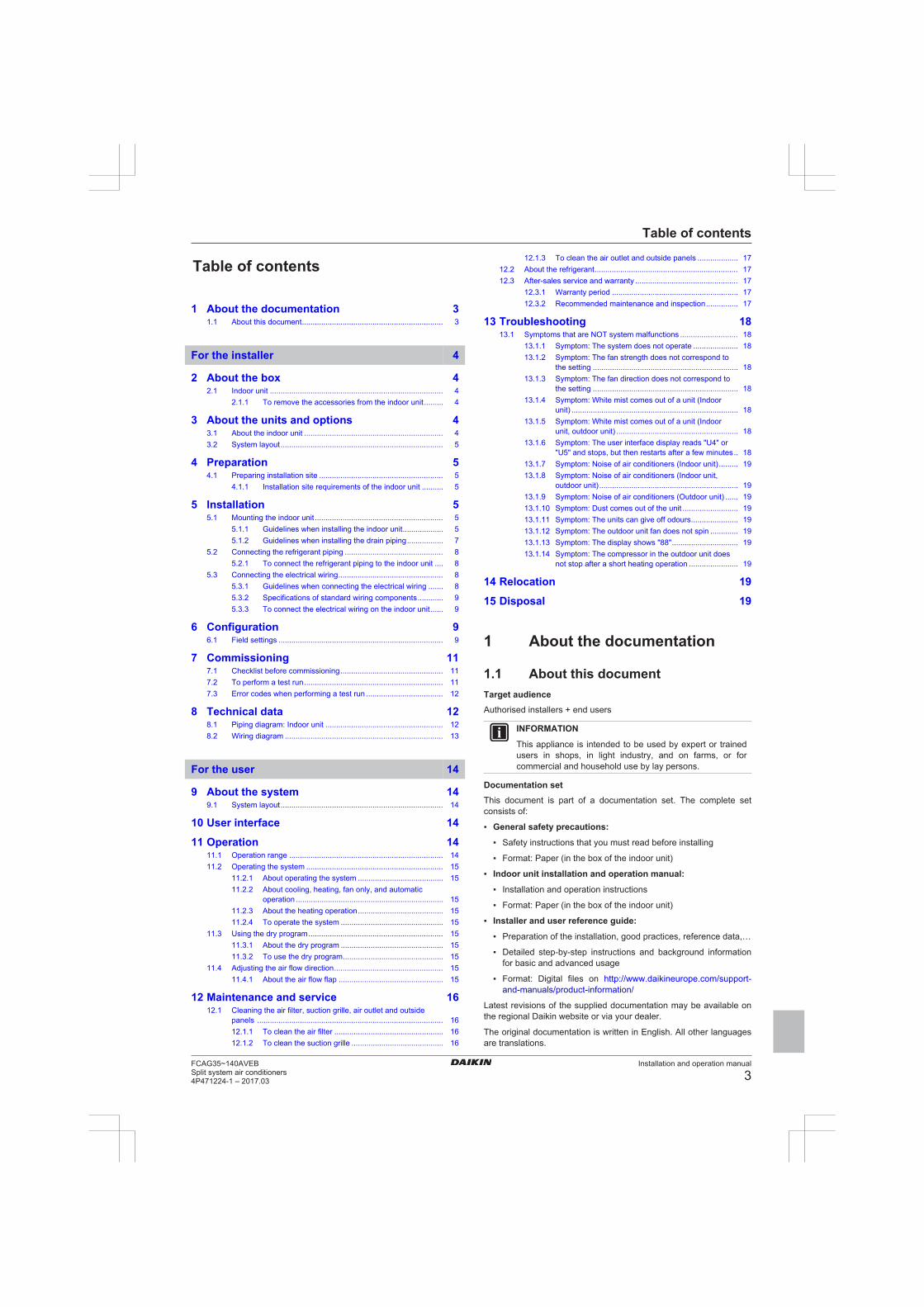
Table of contents
Installation and operation manual
3FCAG35~140AVEBSplit system air conditioners4P471224-1 – 2017.03
Table of contents
1 About the documentation 31.1 About this document.................................................................. 3
For the installer 4
2 About the box 42.1 Indoor unit ................................................................................. 4
2.1.1 To remove the accessories from the indoor unit......... 4
3 About the units and options 43.1 About the indoor unit ................................................................. 43.2 System layout............................................................................ 5
4 Preparation 54.1 Preparing installation site .......................................................... 5
4.1.1 Installation site requirements of the indoor unit .......... 5
5 Installation 55.1 Mounting the indoor unit ............................................................ 5
5.1.1 Guidelines when installing the indoor unit................... 55.1.2 Guidelines when installing the drain piping................. 7
5.2 Connecting the refrigerant piping .............................................. 85.2.1 To connect the refrigerant piping to the indoor unit .... 8
5.3 Connecting the electrical wiring................................................. 85.3.1 Guidelines when connecting the electrical wiring ....... 85.3.2 Specifications of standard wiring components............ 95.3.3 To connect the electrical wiring on the indoor unit...... 9
6 Configuration 96.1 Field settings ............................................................................. 9
7 Commissioning 117.1 Checklist before commissioning................................................ 117.2 To perform a test run................................................................. 117.3 Error codes when performing a test run .................................... 12
8 Technical data 128.1 Piping diagram: Indoor unit ....................................................... 128.2 Wiring diagram .......................................................................... 13
For the user 14
9 About the system 149.1 System layout............................................................................ 14
10 User interface 14
11 Operation 1411.1 Operation range ........................................................................ 1411.2 Operating the system ................................................................ 15
11.2.1 About operating the system ........................................ 1511.2.2 About cooling, heating, fan only, and automatic
operation ..................................................................... 1511.2.3 About the heating operation........................................ 1511.2.4 To operate the system ................................................ 15
11.3 Using the dry program............................................................... 1511.3.1 About the dry program ................................................ 1511.3.2 To use the dry program............................................... 15
11.4 Adjusting the air flow direction................................................... 1511.4.1 About the air flow flap ................................................. 15
12 Maintenance and service 1612.1 Cleaning the air filter, suction grille, air outlet and outside
panels ....................................................................................... 1612.1.1 To clean the air filter ................................................... 1612.1.2 To clean the suction grille ........................................... 16
12.1.3 To clean the air outlet and outside panels ................... 1712.2 About the refrigerant................................................................... 1712.3 After-sales service and warranty ................................................ 17
12.3.1 Warranty period ........................................................... 1712.3.2 Recommended maintenance and inspection............... 17
13 Troubleshooting 1813.1 Symptoms that are NOT system malfunctions ........................... 18
13.1.1 Symptom: The system does not operate ..................... 1813.1.2 Symptom: The fan strength does not correspond to
the setting .................................................................... 1813.1.3 Symptom: The fan direction does not correspond to
the setting .................................................................... 1813.1.4 Symptom: White mist comes out of a unit (Indoor
unit) .............................................................................. 1813.1.5 Symptom: White mist comes out of a unit (Indoor
unit, outdoor unit) ......................................................... 1813.1.6 Symptom: The user interface display reads "U4" or
"U5" and stops, but then restarts after a few minutes.. 1813.1.7 Symptom: Noise of air conditioners (Indoor unit)......... 1913.1.8 Symptom: Noise of air conditioners (Indoor unit,
outdoor unit)................................................................. 1913.1.9 Symptom: Noise of air conditioners (Outdoor unit) ...... 1913.1.10 Symptom: Dust comes out of the unit .......................... 1913.1.11 Symptom: The units can give off odours...................... 1913.1.12 Symptom: The outdoor unit fan does not spin ............. 1913.1.13 Symptom: The display shows "88"............................... 1913.1.14 Symptom: The compressor in the outdoor unit does
not stop after a short heating operation ....................... 19
14 Relocation 19
15 Disposal 19
1 About the documentation
1.1 About this documentTarget audienceAuthorised installers + end users
INFORMATION
This appliance is intended to be used by expert or trainedusers in shops, in light industry, and on farms, or forcommercial and household use by lay persons.
Documentation setThis document is part of a documentation set. The complete setconsists of:
▪ General safety precautions:
▪ Safety instructions that you must read before installing
▪ Format: Paper (in the box of the indoor unit)
▪ Indoor unit installation and operation manual:
▪ Installation and operation instructions
▪ Format: Paper (in the box of the indoor unit)
▪ Installer and user reference guide:
▪ Preparation of the installation, good practices, reference data,…
▪ Detailed step-by-step instructions and background informationfor basic and advanced usage
▪ Format: Digital files on http://www.daikineurope.com/support-and-manuals/product-information/
Latest revisions of the supplied documentation may be available onthe regional Daikin website or via your dealer.
The original documentation is written in English. All other languagesare translations.

2 About the box
Installation and operation manual
4FCAG35~140AVEB
Split system air conditioners4P471224-1 – 2017.03
Technical engineering data▪ A subset of the latest technical data is available on the regional
Daikin website (publicly accessible).
▪ The full set of latest technical data is available on the Daikinextranet (authentication required).
For the installer
2 About the box
2.1 Indoor unit
2.1.1 To remove the accessories from theindoor unit
8× 4×1×1× 1×a
4×1×1×
1×
1×
7×
1×
e fdcb
h ji
g
k
l m
a Paper pattern for installation (upper part of packing)b General safety precautionsc Indoor unit installation and operation manuald Installation guidee Washers for hanger bracketsf Screws (to temporarily attach the paper pattern for
installation to the indoor unit)g Cable tiesh Metal clampi Insulation piece (drain pipe)j Sealing pads: Large (drain pipe), medium 1 (gas pipe),
medium 2 (liquid pipe), small (electrical wiring)k Drain hosel Insulation piece: Small (liquid pipe)
m Insulation piece: Large (gas pipe)
3 About the units and options
3.1 About the indoor unitUse the system in the following temperature and humidity ranges forsafe and effective operation.
For combination with R410A outdoor unit, refer to the following table:
Outdoor units Cooling HeatingRR71~125 Outdoor
temperature–15~46°C DB —
Indoortemperature
18~37°C DB
12~28°C WB
—
RQ71~125 Outdoortemperature
–5~46°C DB –9~21°C DB
–10~15°C WBIndoortemperature
18~37°C DB
12~28°C WB
10~27°C DB
Outdoor units Cooling HeatingRXS35~60 Outdoor
temperature–10~46°C DB –15~24°C DB
–16~18°C WBIndoortemperature
18~32°C DB 10~30°C DB
3MXS40~68
4MXS68~80
5MXS90
Outdoortemperature
–10~46°C DB –15~24°C DB
–16~18°C WBIndoortemperature
18~32°C DB 10~30°C DB
RZQG71~140 Outdoortemperature
–15~50°C DB –19~21°C DB
–20~15.5°C WBIndoortemperature
18~37°C DB
12~28°C WB
10~27°C DB
RZQSG71~140 Outdoortemperature
–15~46°C DB –14~21°C DB
–15~15.5°C WBIndoortemperature
20~37°C DB
14~28°C WB
10~27°C DB
RZQ200~250 Outdoortemperature
–5~46°C DB –14~21°C DB
–15~15°C WBIndoortemperature
20~37°C DB
14~28°C WB
10~27°C DB
AZQS71~125 Outdoortemperature
–15~46°C DB –14~21°C DB
–15~15.5°C WBIndoortemperature
20~37°C DB
14~28°C WB
10~27°C DB
For combination with R32 outdoor unit, refer to the following table:
Outdoor units Cooling HeatingRXM35~60 Outdoor
temperature–10~46°C DB –15~24°C DB
–16~18°C WBIndoortemperature
18~32°C DB 10~30°C DB
3MXM40~68
4MXM68~80
5MXM90
Outdoortemperature
–10~46°C DB –15~24°C DB
–16~18°C WBIndoortemperature
18~32°C DB 10~30°C DB
RZAG71~140 Outdoortemperature
–20~52°C DB –19.5~21°C DB
–20~15.5°C WBIndoortemperature
18~37°C DB
12~28°C WB
10~27°C DB
RZASG71~140 Outdoortemperature
–15~46°C DB –14~21°C DB
–15~15.5°C WBIndoortemperature
20~37°C DB
14~28°C WB
10~27°C DB
4 Preparation
Installation and operation manual
5FCAG35~140AVEBSplit system air conditioners4P471224-1 – 2017.03
Outdoor units Cooling HeatingAZAS71~140 Outdoor
temperature–15~46°C DB –14~21°C DB
–15~15.5°C WBIndoortemperature
20~37°C DB
14~28°C WB
10~27°C DB
Indoor humidity ≤80%(a)
(a) To avoid condensation and water dripping out of the unit. Ifthe temperature or the humidity is beyond these conditions,safety devices may be put in action and the air conditionermay not operate.
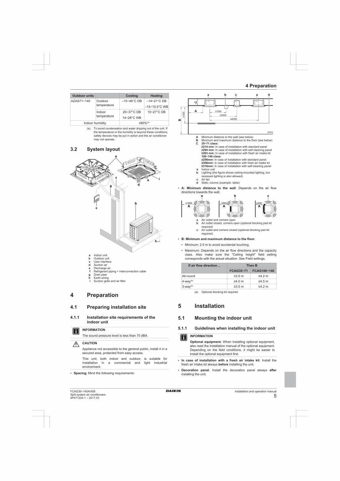
3.2 System layouta
bc
de if
g
h
a Indoor unitb Outdoor unitc User interfaced Suction aire Discharge airf Refrigerant piping + interconnection cableg Drain pipeh Earth wiringi Suction grille and air filter
4 Preparation
4.1 Preparing installation site
4.1.1 Installation site requirements of theindoor unit
INFORMATION
The sound pressure level is less than 70 dBA.
CAUTION
Appliance not accessible to the general public, install it in asecured area, protected from easy access.
This unit, both indoor and outdoor, is suitable forinstallation in a commercial and light industrialenvironment.
▪ Spacing. Mind the following requirements:
(mm)
≥1500≥2000
≥4000
≥1500 A
B
C
ba dac
A Minimum distance to the wall (see below)B Minimum and maximum distance to the floor (see below)C 35~71 class:
≥214 mm: In case of installation with standard panel≥294 mm: In case of installation with self-cleaning panel≥263 mm: In case of installation with fresh air intake kit100~140 class:≥256mm: In case of installation with standard panel≥306mm: In case of installation with fresh air intake kit≥316mm: In case of installation with self-cleaning panel
a Indoor unitb Lighting (the figure shows ceiling-mounted lighting, but
recessed lighting is also allowed)c Air fand Static volume (example: table)
▪ A: Minimum distance to the wall. Depends on the air flowdirections towards the wall.
≥1500 ≥500 ≥200
a
A A A
b c
a Air outlet and corners openb Air outlet closed, corners open (optional blocking pad kit
required)c Air outlet and corners closed (optional blocking pad kit
required)
▪ B: Minimum and maximum distance to the floor:
▪ Minimum: 2.5 m to avoid accidental touching.
▪ Maximum: Depends on the air flow directions and the capacityclass. Also make sure the "Ceiling height" field settingcorresponds with the actual situation. See Field settings.
If air flow direction… Then BFCAG35~71 FCAG100~140
All-round ≤3.5 m ≤4.2 m4-way(a) ≤4.0 m ≤4.5 m3-way(a) ≤3.5 m ≤4.2 m
(a) Optional blocking kit required
5 Installation
5.1 Mounting the indoor unit
5.1.1 Guidelines when installing the indoor unit
INFORMATION
Optional equipment. When installing optional equipment,also read the installation manual of the optional equipment.Depending on the field conditions, it might be easier toinstall the optional equipment first.
▪ In case of installation with a fresh air intake kit. Install thefresh air intake kit always before installing the unit.
▪ Decoration panel. Install the decoration panel always afterinstalling the unit.
5 Installation
Installation and operation manual
6FCAG35~140AVEB
Split system air conditioners4P471224-1 – 2017.03
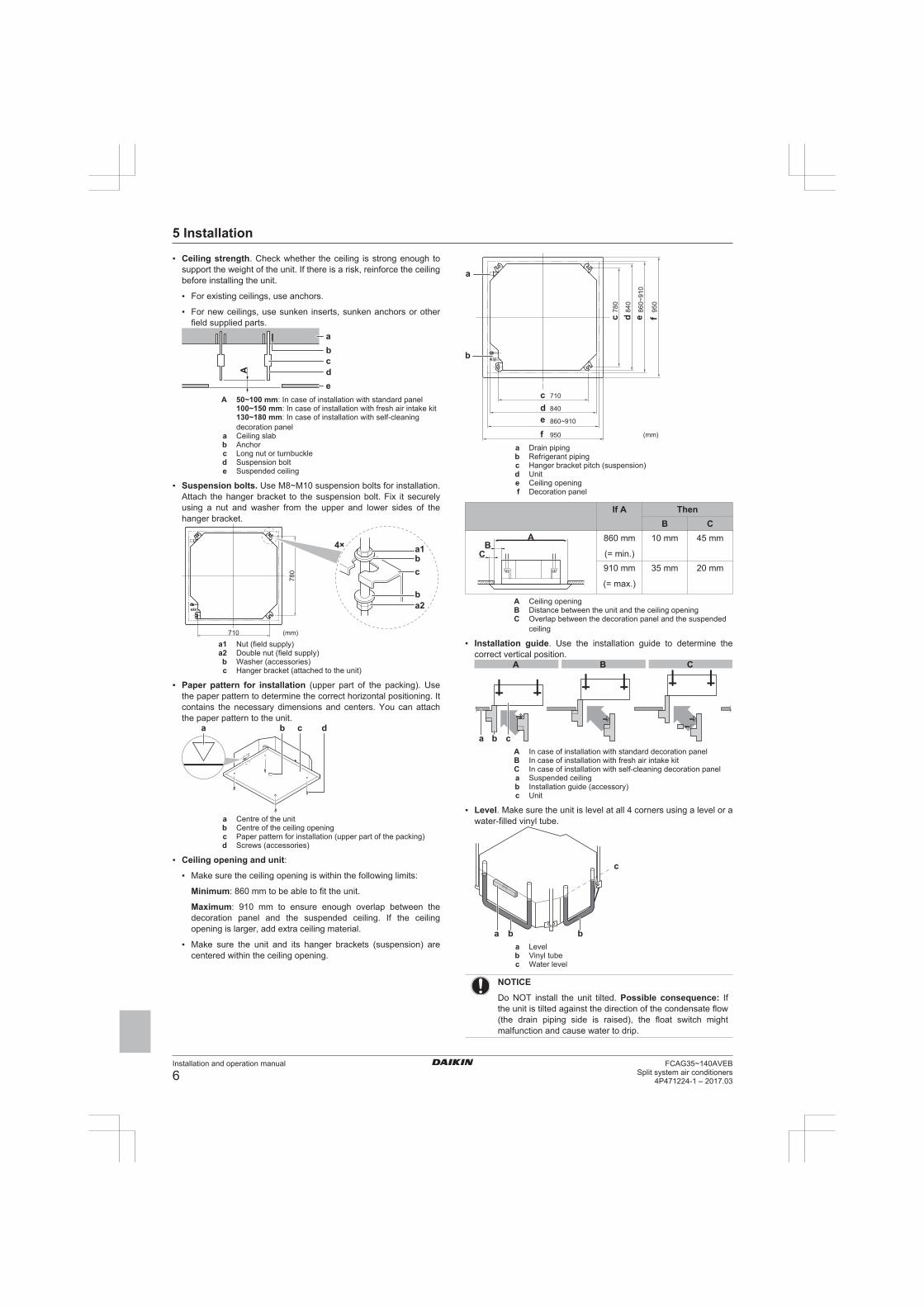
▪ Ceiling strength. Check whether the ceiling is strong enough tosupport the weight of the unit. If there is a risk, reinforce the ceilingbefore installing the unit.
▪ For existing ceilings, use anchors.
▪ For new ceilings, use sunken inserts, sunken anchors or otherfield supplied parts.
A
cb
de
a
A 50~100 mm: In case of installation with standard panel100~150 mm: In case of installation with fresh air intake kit130~180 mm: In case of installation with self-cleaningdecoration panel
a Ceiling slabb Anchorc Long nut or turnbuckled Suspension bolte Suspended ceiling
▪ Suspension bolts. Use M8~M10 suspension bolts for installation.Attach the hanger bracket to the suspension bolt. Fix it securelyusing a nut and washer from the upper and lower sides of thehanger bracket.
(mm)
780
710
a1b
ba2
c
4×
a1 Nut (field supply)a2 Double nut (field supply)b Washer (accessories)c Hanger bracket (attached to the unit)
▪ Paper pattern for installation (upper part of the packing). Usethe paper pattern to determine the correct horizontal positioning. Itcontains the necessary dimensions and centers. You can attachthe paper pattern to the unit.
a cb d
a Centre of the unitb Centre of the ceiling openingc Paper pattern for installation (upper part of the packing)d Screws (accessories)
▪ Ceiling opening and unit:
▪ Make sure the ceiling opening is within the following limits:
Minimum: 860 mm to be able to fit the unit.
Maximum: 910 mm to ensure enough overlap between thedecoration panel and the suspended ceiling. If the ceilingopening is larger, add extra ceiling material.
▪ Make sure the unit and its hanger brackets (suspension) arecentered within the ceiling opening.
(mm)
710
840
860~910
950
cdef
780
840
860~
910
950
c d e f
a
b
a Drain pipingb Refrigerant pipingc Hanger bracket pitch (suspension)d Unite Ceiling openingf Decoration panel
If A ThenB C
A
CB
860 mm
(= min.)
10 mm 45 mm
910 mm
(= max.)
35 mm 20 mm
A Ceiling openingB Distance between the unit and the ceiling openingC Overlap between the decoration panel and the suspended
ceiling
▪ Installation guide. Use the installation guide to determine thecorrect vertical position.
A B C
a b cA In case of installation with standard decoration panelB In case of installation with fresh air intake kitC In case of installation with self-cleaning decoration panela Suspended ceilingb Installation guide (accessory)c Unit
▪ Level. Make sure the unit is level at all 4 corners using a level or awater-filled vinyl tube.
c
bbaa Levelb Vinyl tubec Water level
NOTICE
Do NOT install the unit tilted. Possible consequence: Ifthe unit is tilted against the direction of the condensate flow(the drain piping side is raised), the float switch mightmalfunction and cause water to drip.
5 Installation
Installation and operation manual
7FCAG35~140AVEBSplit system air conditioners4P471224-1 – 2017.03
5.1.2 Guidelines when installing the drainpiping
Make sure condensation water can be evacuated properly. Thisinvolves:
▪ General guidelines
▪ Connecting the drain piping to the indoor unit
▪ Checking for water leaks
General guidelines▪ Pipe length. Keep drain piping as short as possible.
▪ Pipe size. Keep the pipe size equal to or greater than that of theconnecting pipe (vinyl pipe of 25 mm nominal diameter and32 mm outer diameter).
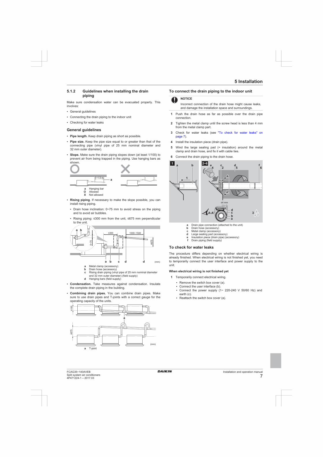
▪ Slope. Make sure the drain piping slopes down (at least 1/100) toprevent air from being trapped in the piping. Use hanging bars asshown.
1~1.5 m a
a Hanging barO AllowedX Not allowed
▪ Rising piping. If necessary to make the slope possible, you caninstall rising piping.
▪ Drain hose inclination: 0~75 mm to avoid stress on the pipingand to avoid air bubbles.
▪ Rising piping: ≤300 mm from the unit, ≤675 mm perpendicularto the unit.
≤675
≤300
0~75
1000~1500
(mm)
ba
b ca dda Metal clamp (accessory)b Drain hose (accessory)c Rising drain piping (vinyl pipe of 25 mm nominal diameter
and 32 mm outer diameter) (field supply)d Hanging bars (field supply)
▪ Condensation. Take measures against condensation. Insulatethe complete drain piping in the building.
▪ Combining drain pipes. You can combine drain pipes. Makesure to use drain pipes and T-joints with a correct gauge for theoperating capacity of the units.
≥100
≤675
(mm)
a
a T-joint
To connect the drain piping to the indoor unit
NOTICE
Incorrect connection of the drain hose might cause leaks,and damage the installation space and surroundings.
1 Push the drain hose as far as possible over the drain pipeconnection.
2 Tighten the metal clamp until the screw head is less than 4 mmfrom the metal clamp part.
3 Check for water leaks (see "To check for water leaks" onpage 7).
4 Install the insulation piece (drain pipe).
5 Wind the large sealing pad (= insulation) around the metalclamp and drain hose, and fix it with cable ties.
6 Connect the drain piping to the drain hose.
≤4 mm
A
A'
A-A'
A
A'
f652
ce4
ba d
ba
dc 3
1
2~61
a Drain pipe connection (attached to the unit)b Drain hose (accessory)c Metal clamp (accessory)d Large sealing pad (accessory)e Insulation piece (drain pipe) (accessory)f Drain piping (field supply)
To check for water leaksThe procedure differs depending on whether electrical wiring isalready finished. When electrical wiring is not finished yet, you needto temporarily connect the user interface and power supply to theunit.
When electrical wiring is not finished yet
1 Temporarily connect electrical wiring.
▪ Remove the switch box cover (a).▪ Connect the user interface (b).▪ Connect the power supply (1~ 220-240 V 50/60 Hz) and
earth (c).▪ Reattach the switch box cover (a).
5 Installation
Installation and operation manual
8FCAG35~140AVEB
Split system air conditioners4P471224-1 – 2017.03
b
a
c
Forced OFF Transm.
T1 T2
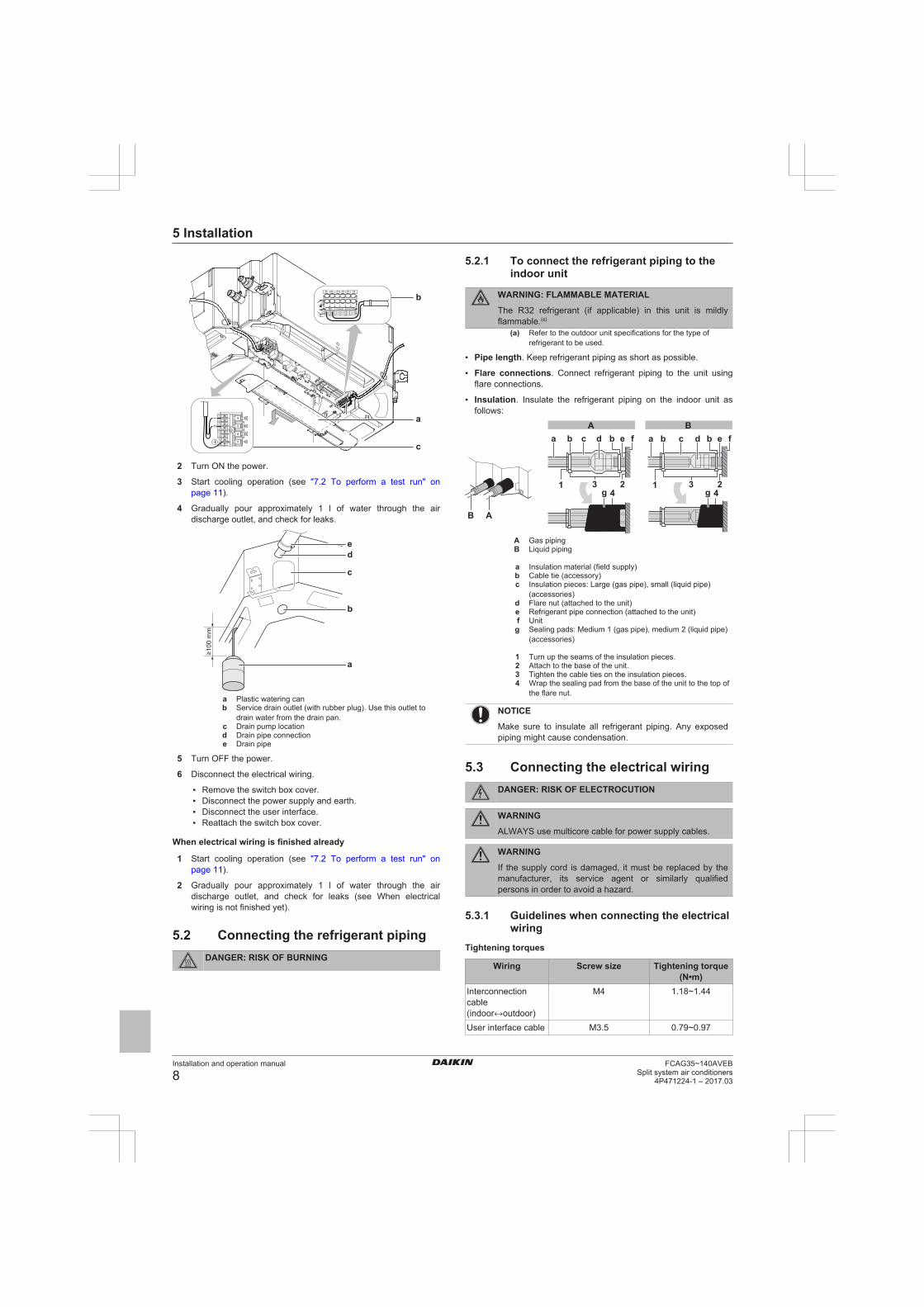
2 Turn ON the power.
3 Start cooling operation (see "7.2 To perform a test run" onpage 11).
4 Gradually pour approximately 1 l of water through the airdischarge outlet, and check for leaks.
≥100
mm
ed
c
b
a
a Plastic watering canb Service drain outlet (with rubber plug). Use this outlet to
drain water from the drain pan.c Drain pump locationd Drain pipe connectione Drain pipe
5 Turn OFF the power.
6 Disconnect the electrical wiring.
▪ Remove the switch box cover.▪ Disconnect the power supply and earth.▪ Disconnect the user interface.▪ Reattach the switch box cover.
When electrical wiring is finished already
1 Start cooling operation (see "7.2 To perform a test run" onpage 11).
2 Gradually pour approximately 1 l of water through the airdischarge outlet, and check for leaks (see When electricalwiring is not finished yet).
5.2 Connecting the refrigerant pipingDANGER: RISK OF BURNING
5.2.1 To connect the refrigerant piping to theindoor unit
WARNING: FLAMMABLE MATERIAL
The R32 refrigerant (if applicable) in this unit is mildlyflammable.(a)
(a) Refer to the outdoor unit specifications for the type ofrefrigerant to be used.
▪ Pipe length. Keep refrigerant piping as short as possible.
▪ Flare connections. Connect refrigerant piping to the unit usingflare connections.
▪ Insulation. Insulate the refrigerant piping on the indoor unit asfollows:
A Ba dc e fb b a dc e fb b
24
3g
1 234g
AB
1
A Gas pipingB Liquid piping
a Insulation material (field supply)b Cable tie (accessory)c Insulation pieces: Large (gas pipe), small (liquid pipe)
(accessories)d Flare nut (attached to the unit)e Refrigerant pipe connection (attached to the unit)f Unitg Sealing pads: Medium 1 (gas pipe), medium 2 (liquid pipe)
(accessories)
1 Turn up the seams of the insulation pieces.2 Attach to the base of the unit.3 Tighten the cable ties on the insulation pieces.4 Wrap the sealing pad from the base of the unit to the top of
the flare nut.
NOTICE
Make sure to insulate all refrigerant piping. Any exposedpiping might cause condensation.
5.3 Connecting the electrical wiringDANGER: RISK OF ELECTROCUTION
WARNING
ALWAYS use multicore cable for power supply cables.
WARNING
If the supply cord is damaged, it must be replaced by themanufacturer, its service agent or similarly qualifiedpersons in order to avoid a hazard.
5.3.1 Guidelines when connecting the electricalwiring
Tightening torques
Wiring Screw size Tightening torque(N•m)
Interconnectioncable(indoor↔outdoor)
M4 1.18~1.44
User interface cable M3.5 0.79~0.97

6 Configuration
Installation and operation manual
9FCAG35~140AVEBSplit system air conditioners4P471224-1 – 2017.03
5.3.2 Specifications of standard wiringcomponents
Component SpecificationInterconnection cable(indoor↔outdoor)
Minimum cable section of2.5 mm² and applicable for
230 VUser interface cable Vinyl cords with 0.75 to
1.25 mm² sheath or cables(2‑core wires)
Maximum 500 m
5.3.3 To connect the electrical wiring on theindoor unit
NOTICE
▪ Follow the wiring diagram (delivered with the unit,located at the inside of the service cover).
▪ For instructions on how to connect the decoration paneland the sensor kit, see the installation manual deliveredwith the panel or the kit.
▪ Make sure the electrical wiring does NOT obstructproper reattachment of the service cover.
It is important to keep the power supply and the transmission wiringseparated from each other. In order to avoid any electricalinterference the distance between both wiring should always be atleast 50 mm.
NOTICE
Be sure to keep the power line and transmission line apartfrom each other. Transmission wiring and power supplywiring may cross, but may not run parallel.
1 Remove the service cover.
2 User interface cable: Route the cable through the frame,connect the cable to the terminal block, and fix the cable with acable tie.
3 Interconnection cable (indoor↔outdoor): Route the cablethrough the frame, connect the cable to the terminal block(make sure the numbers match with the numbers on theoutdoor unit, and connect the earth wire), and fix the cable witha cable tie.
4 Divide the small sealing (accessory) and wrap it around thecables to prevent water from entering the unit. Seal all gaps toprevent small animals from entering the system.
WARNING
Provide adequate measures to prevent that the unit can beused as a shelter by small animals. Small animals thatmake contact with electrical parts can cause malfunctions,smoke or fire.
5 Reattach the service cover.
▪ Following installation is for pair type or multi-system. For moreinstallation options, see the Installer reference guide of the indoorunit.
1~ 50 Hz220-240 V
b
a
e1
cd
a Interconnection cableb Power supply cablec Earth leakage circuit breakerd Fuse
e1 Main user interface
Forced OFF Transm.
T1 T2
70~90
710
~15
70~9
010
~20
(mm)
10~15d
e
a
b
e
cd
c
b
a Service cover (with wiring diagram on the back)b Opening for cablesc Connection of interconnection cable (including earth)d Cable tiee Connection of user interface cable
6 Configuration
6.1 Field settingsMake the following field settings so that they correspond with theactual installation setup and with the needs of the user:
▪ Ceiling height
▪ Air flow direction
▪ Air volume when thermostat control is OFF
▪ Time to clean air filter
Setting: Ceiling heightThis setting must correspond with the actual distance to the floor,capacity class and air flow directions.
▪ For 3-way and 4-way air flows (which require an optional blockingpad kit), see the installation manual of the optional blocking padkit.
▪ For all-round air flow, use the table below.
6 Configuration
Installation and operation manual
10FCAG35~140AVEB
Split system air conditioners4P471224-1 – 2017.03
If the distance to the floor is (m) Then1
M C1 C2≤2.7 13 (23) 0 012.7<x≤3.0 023.0<x≤3.5 03
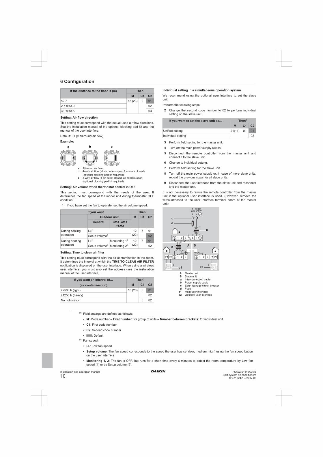
Setting: Air flow directionThis setting must correspond with the actual used air flow directions.See the installation manual of the optional blocking pad kit and themanual of the user interface.
Default: 01 (= all-round air flow)
Example:
1
2
3
4
1
2
3
4
1
2
3
a b c
a All-round air flowb 4-way air flow (all air outlets open, 2 corners closed)
(optional blocking pad kit required)c 3-way air flow (1 air outlet closed, all corners open)
(optional blocking pad kit required)
Setting: Air volume when thermostat control is OFFThis setting must correspond with the needs of the user. Itdetermines the fan speed of the indoor unit during thermostat OFFcondition.
1 If you have set the fan to operate, set the air volume speed:
If you want Then1
Outdoor unit M C1 C2General 3MX+4MX
+5MXDuring coolingoperation
LL2 12(22)
6 01Setup volume2 02
During heatingoperation
LL2 Monitoring 12 12(22)
3 01Setup volume2 Monitoring 22 02
Setting: Time to clean air filterThis setting must correspond with the air contamination in the room.It determines the interval at which the TIME TO CLEAN AIR FILTERnotification is displayed on the user interface. When using a wirelessuser interface, you must also set the address (see the installationmanual of the user interface).
If you want an interval of…
(air contamination)
Then1
M C1 C2
±2500 h (light) 10 (20) 0 01±1250 h (heavy) 02No notification 3 02
Individual setting in a simultaneous operation systemWe recommend using the optional user interface to set the slaveunit.
Perform the following steps:
2 Change the second code number to 02 to perform individualsetting on the slave unit.
If you want to set the slave unit as… Then1
M C1 C2Unified setting 21(11) 01 01Individual setting 02
3 Perform field setting for the master unit.
4 Turn off the main power supply switch.
5 Disconnect the remote controller from the master unit andconnect it to the slave unit.
6 Change to individual setting.
7 Perform field setting for the slave unit.
8 Turn off the main power supply or, in case of more slave units,repeat the previous steps for all slave units.
9 Disconnect the user interface from the slave unit and reconnectit to the master unit.
It is not necessary to rewire the remote controller from the masterunit if the optional user interface is used. (However, remove thewires attached to the user interface terminal board of the masterunit)
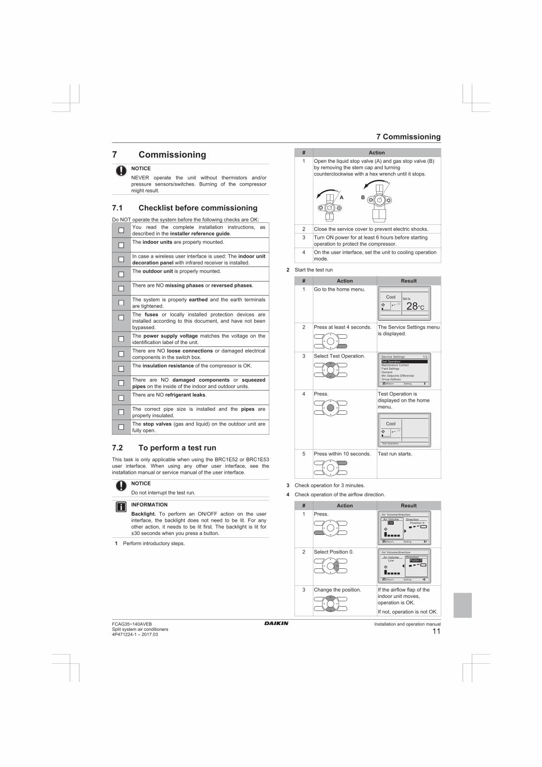
1~ 50 Hz220-240 V
b
a
e1
A B
e2
cd
A Master unitB Slave unita Interconnection cableb Power supply cablec Earth leakage circuit breakerd Fuse
e1 Main user interfacee2 Optional user interface
(1) Field settings are defined as follows:
▪ M: Mode number – First number: for group of units – Number between brackets: for individual unit
▪ C1: First code number
▪ C2: Second code number
▪ : Default(2) Fan speed:
▪ LL: Low fan speed
▪ Setup volume: The fan speed corresponds to the speed the user has set (low, medium, high) using the fan speed buttonon the user interface.
▪ Monitoring 1, 2: The fan is OFF, but runs for a short time every 6 minutes to detect the room temperature by Low fanspeed (1) or by Setup volume (2).
7 Commissioning
Installation and operation manual
11FCAG35~140AVEBSplit system air conditioners4P471224-1 – 2017.03
7 CommissioningNOTICE
NEVER operate the unit without thermistors and/orpressure sensors/switches. Burning of the compressormight result.
7.1 Checklist before commissioningDo NOT operate the system before the following checks are OK:
You read the complete installation instructions, asdescribed in the installer reference guide.The indoor units are properly mounted.
In case a wireless user interface is used: The indoor unitdecoration panel with infrared receiver is installed.The outdoor unit is properly mounted.
There are NO missing phases or reversed phases.
The system is properly earthed and the earth terminalsare tightened.The fuses or locally installed protection devices areinstalled according to this document, and have not beenbypassed.The power supply voltage matches the voltage on theidentification label of the unit.There are NO loose connections or damaged electricalcomponents in the switch box.The insulation resistance of the compressor is OK.
There are NO damaged components or squeezedpipes on the inside of the indoor and outdoor units.There are NO refrigerant leaks.
The correct pipe size is installed and the pipes areproperly insulated.The stop valves (gas and liquid) on the outdoor unit arefully open.
7.2 To perform a test runThis task is only applicable when using the BRC1E52 or BRC1E53user interface. When using any other user interface, see theinstallation manual or service manual of the user interface.
NOTICE
Do not interrupt the test run.
INFORMATION
Backlight. To perform an ON/OFF action on the userinterface, the backlight does not need to be lit. For anyother action, it needs to be lit first. The backlight is lit for±30 seconds when you press a button.
1 Perform introductory steps.
# Action1 Open the liquid stop valve (A) and gas stop valve (B)
by removing the stem cap and turningcounterclockwise with a hex wrench until it stops.
A B
2 Close the service cover to prevent electric shocks.3 Turn ON power for at least 6 hours before starting
operation to protect the compressor.4 On the user interface, set the unit to cooling operation
mode.
2 Start the test run
# Action Result1 Go to the home menu.
Cool Set to
28°C
2 Press at least 4 seconds. The Service Settings menuis displayed.
3 Select Test Operation.
Return Setting
Service Settings 1/3Test OperationMaintenance ContactField SettingsDemandMin Setpoints DifferentialGroup Address
4 Press. Test Operation isdisplayed on the homemenu.
Cool
Return SettingTest Operation
5 Press within 10 seconds. Test run starts.
3 Check operation for 3 minutes.
4 Check operation of the airflow direction.
# Action Result1 Press.
Return SettingReturn Setting
Air Volume/direction
Air Volume DirectionPosition 0Low
2 Select Position 0.
Return SettingReturn Setting
Air Volume/direction
Air Volume DirectionLow Position 0
3 Change the position. If the airflow flap of theindoor unit moves,operation is OK.
If not, operation is not OK.

8 Technical data
Installation and operation manual
12FCAG35~140AVEB
Split system air conditioners4P471224-1 – 2017.03
# Action Result4 Press. The home menu is
displayed.
5 Stop the test run.
# Action Result1 Press at least 4 seconds. The Service Settings menu
is displayed.
2 Select Test Operation.
Return Setting
Service Settings 1/3Test OperationMaintenance ContactField SettingsDemandMin Setpoints DifferentialGroup Address
3 Press. The unit returns to normaloperation, and the homemenu is displayed.
7.3 Error codes when performing atest run
If the installation of the outdoor unit has NOT been done correctly,the following error codes may be displayed on the user interface:
Error code Possible causeNothing displayed
(the currently settemperature is notdisplayed)
▪ The wiring is disconnected or there is awiring error (between power supply andoutdoor unit, between outdoor unit andindoor units, between indoor unit anduser interface).
▪ The fuse on the outdoor or indoor unitPCB has blown.
E3, E4 or L8 ▪ The stop valves are closed.
▪ The air inlet or air outlet is blocked.E7 There is a missing phase in case of three-
phase power supply units.
Note: Operation will be impossible. TurnOFF the power, recheck the wiring, andswitch two of the three electrical wires.
L4 The air inlet or air outlet is blocked.U0 The stop valves are closed.U2 ▪ There is a voltage imbalance.
▪ There is a missing phase in case ofthree-phase power supply units. Note:Operation will be impossible. Turn OFFthe power, recheck the wiring, and switchtwo of the three electrical wires.
U4 or UF The inter-unit branch wiring is not correct.UA The outdoor and indoor unit are
incompatible.
8 Technical data▪ A subset of the latest technical data is available on the regional
Daikin website (publicly accessible).
▪ The full set of latest technical data is available on the Daikinextranet (authentication required).
8.1 Piping diagram: Indoor unit
b
a
c
a Liquid pipe connectionb Gas pipe connectionc Heat exchanger

8 Technical data
Installation and operation manual
13FCAG35~140AVEBSplit system air conditioners4P471224-1 – 2017.03
8.2 Wiring diagram
Unified Wiring Diagram LegendFor applied parts and numbering refer to the wiring diagram sticker supplied on the unit. Part numbering is realized by Arabic numbers in ascending order for each part and
is represented in the overview below by symbol “*” in the part code.
: CIRCUIT BREAKER : PROTECTIVE EARTH
: CONNECTION : PROTECTIVE EARTH (SCREW)
, : CONNECTOR A : RECTIFIER
: EARTH : RELAY CONNECTOR
: FIELD WIRING : SHORT CIRCUIT CONNECTOR
: FUSE : TERMINAL
INDOOR
: INDOOR UNIT : TERMINAL STRIP
OUTDOOR
: OUTDOOR UNIT : WIRE CLAMP
BLK : BLACK GRN : GREEN PNK : PINK WHT : WHITE
BLU : BLUE GRY : GREY PRP, PPL : PURPLE YLW : YELLOW
BRN : BROWN ORG : ORANGE RED : RED
A*P : PRINTED CIRCUIT BOARD PS : SWITCHING POWER SUPPLY
BS* : PUSH BUTTON ON / OFF, OPERATION SWITCH PTC* : THERMISTOR PTC
BZ, H*O : BUZZER Q* : INSULATED GATE BIPOLAR TRANSISTOR (IGBT)
C* : CAPACITOR Q*DI : EARTH LEAK CIRCUIT BREAKER
AC*, CN*, E*, HA*, HE, HL*, HN*, HR*, MR*_A, MR*_B, S*, U, V, W, X*A
: CONNECTION, CONNECTOR Q*L : OVERLOAD PROTECTOR
D*, V*D : DIODE Q*M : THERMO SWITCH
DB* : DIODE BRIDGE R* : RESISTOR
DS* : DIP SWITCH R*T : THERMISTOR
E*H : HEATER RC : RECEIVER
F*U, FU* (FOR CHARACTERISTICS REFER TO PCB INSIDE YOUR UNIT)
: FUSE S*C : LIMIT SWITCH
FG* : CONNECTOR (FRAME GROUND) S*L : FLOAT SWITCH
H* : HARNESS S*NPH : PRESSURE SENSOR (HIGH)
H*P, LED*, V*L : PILOT LAMP, LIGHT EMITTING DIODE S*NPL : PRESSURE SENSOR (LOW)
HAP : LIGHT EMITTING DIODE (SERVICE MONITOR GREEN) S*PH, HPS* : PRESSURE SWITCH (HIGH)
HIGH VOLTAGE : HIGH VOLTAGE S*PL : PRESSURE SWITCH (LOW)
IES : INTELLIGENT EYE SENSOR S*T : THERMOSTAT
IPM* : INTELLIGENT POWER MODULE S*W, SW* : OPERATION SWITCH
K*R, KCR, KFR, KHuR : MAGNETIC RELAY SA* : SURGE ARRESTOR
L : LIVE SR*, WLU : SIGNAL RECEIVER
L* : COIL SS* : SELECTOR SWITCH
L*R : REACTOR SHEET METAL : TERMINAL STRIP FIXED PLATE
M* : STEPPER MOTOR T*R : TRANSFORMER
M*C : COMPRESSOR MOTOR TC, TRC : TRANSMITTER
M*F : FAN MOTOR V*, R*V : VARISTOR
M*P : DRAIN PUMP MOTOR V*R : DIODE BRIDGE
M*S : SWING MOTOR WRC : WIRELESS REMOTE CONTROLLER
MR*, MRCW*, MRM*, MRN* : MAGNETIC RELAY X* : TERMINAL
N : NEUTRAL X*M : TERMINAL STRIP (BLOCK)
n = * NUMBER OF PASSES THROUGH FERRITE CORE Y*E : ELECTRONIC EXPANSION VALVE COIL
PAM : PULSE-AMPLITUDE MODULATION Y*R, Y*S : REVERSING SOLENOID VALVE COIL
PCB* : PRINTED CIRCUIT BOARD Z*C : FERRITE CORE
PM* : POWER MODULE ZF, Z*F : NOISE FILTER
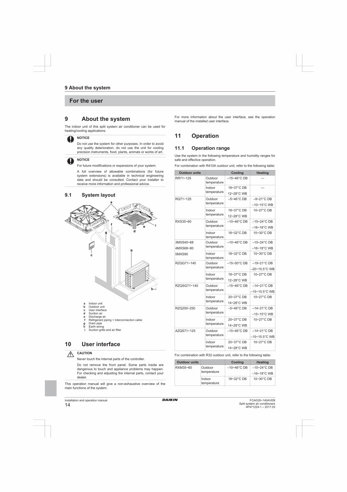
9 About the system
Installation and operation manual
14FCAG35~140AVEB
Split system air conditioners4P471224-1 – 2017.03
For the user
9 About the systemThe indoor unit of this split system air conditioner can be used forheating/cooling applications.
NOTICE
Do not use the system for other purposes. In order to avoidany quality deterioration, do not use the unit for coolingprecision instruments, food, plants, animals or works of art.
NOTICE
For future modifications or expansions of your system:
A full overview of allowable combinations (for futuresystem extensions) is available in technical engineeringdata and should be consulted. Contact your installer toreceive more information and professional advice.
9.1 System layouta
bc
de if
g
h
a Indoor unitb Outdoor unitc User interfaced Suction aire Discharge airf Refrigerant piping + interconnection cableg Drain pipeh Earth wiringi Suction grille and air filter
10 User interfaceCAUTION
Never touch the internal parts of the controller.
Do not remove the front panel. Some parts inside aredangerous to touch and appliance problems may happen.For checking and adjusting the internal parts, contact yourdealer.
This operation manual will give a non-exhaustive overview of themain functions of the system.
For more information about the user interface, see the operationmanual of the installed user interface.
11 Operation
11.1 Operation rangeUse the system in the following temperature and humidity ranges forsafe and effective operation.
For combination with R410A outdoor unit, refer to the following table:
Outdoor units Cooling HeatingRR71~125 Outdoor
temperature–15~46°C DB —
Indoortemperature
18~37°C DB
12~28°C WB
—
RQ71~125 Outdoortemperature
–5~46°C DB –9~21°C DB
–10~15°C WBIndoortemperature
18~37°C DB
12~28°C WB
10~27°C DB
RXS35~60 Outdoortemperature
–10~46°C DB –15~24°C DB
–16~18°C WBIndoortemperature
18~32°C DB 10~30°C DB
3MXS40~68
4MXS68~80
5MXS90
Outdoortemperature
–10~46°C DB –15~24°C DB
–16~18°C WBIndoortemperature
18~32°C DB 10~30°C DB
RZQG71~140 Outdoortemperature
–15~50°C DB –19~21°C DB
–20~15.5°C WBIndoortemperature
18~37°C DB
12~28°C WB
10~27°C DB
RZQSG71~140 Outdoortemperature
–15~46°C DB –14~21°C DB
–15~15.5°C WBIndoortemperature
20~37°C DB
14~28°C WB
10~27°C DB
RZQ200~250 Outdoortemperature
–5~46°C DB –14~21°C DB
–15~15°C WBIndoortemperature
20~37°C DB
14~28°C WB
10~27°C DB
AZQS71~125 Outdoortemperature
–15~46°C DB –14~21°C DB
–15~15.5°C WBIndoortemperature
20~37°C DB
14~28°C WB
10~27°C DB
For combination with R32 outdoor unit, refer to the following table:
Outdoor units Cooling HeatingRXM35~60 Outdoor
temperature–10~46°C DB –15~24°C DB
–16~18°C WBIndoortemperature
18~32°C DB 10~30°C DB

11 Operation
Installation and operation manual
15FCAG35~140AVEBSplit system air conditioners4P471224-1 – 2017.03
Outdoor units Cooling Heating3MXM40~68
4MXM68~80
5MXM90
Outdoortemperature
–10~46°C DB –15~24°C DB
–16~18°C WBIndoortemperature
18~32°C DB 10~30°C DB
RZAG71~140 Outdoortemperature
–20~52°C DB –19.5~21°C DB
–20~15.5°C WBIndoortemperature
18~37°C DB
12~28°C WB
10~27°C DB
RZASG71~140 Outdoortemperature
–15~46°C DB –14~21°C DB
–15~15.5°C WBIndoortemperature
20~37°C DB
14~28°C WB
10~27°C DB
AZAS71~140 Outdoortemperature
–15~46°C DB –14~21°C DB
–15~15.5°C WBIndoortemperature
20~37°C DB
14~28°C WB
10~27°C DB
Indoor humidity ≤80%(a)
(a) To avoid condensation and water dripping out of the unit. Ifthe temperature or the humidity is beyond these conditions,safety devices may be put in action and the air conditionermay not operate.
11.2 Operating the system
11.2.1 About operating the system▪ To protect the unit, turn on the main power switch 6 hours before
operation.
▪ If the main power supply is turned off during operation, operationwill restart automatically after the power turns back on again.
11.2.2 About cooling, heating, fan only, andautomatic operation
▪ The air flow rate may adjust itself depending on the roomtemperature or the fan may stop immediately. This is not amalfunction.
11.2.3 About the heating operationIt may take longer to reach the set temperature for general heatingoperation than for cooling operation.
The following operation is performed in order to prevent the heatingcapacity from dropping or cold air from blowing.
Defrost operationIn heating operation, freezing of the outdoor unit's air cooled coilincreases over time, restricting the energy transfer to the outdoorunit's coil. Heating capability decreases and the system needs to gointo defrost operation to be able to deliver enough heat to the indoorunits.
The indoor unit will stop fan operation, the refrigerant cycle willreverse and energy from inside the building will be used to defrostthe outdoor unit coil.
The indoor unit will indicate defrost operation on the display .
Hot startIn order to prevent cold air from blowing out of an indoor unit at thestart of heating operation, the indoor fan is automatically stopped.The display of the user interface shows . It may take sometime before the fan starts. This is not a malfunction.
11.2.4 To operate the system1 Press the operation mode selector button on the user interface
several times and select the operation mode of your choice.
Cooling operation
Heating operation
Fan only operation
2 Press the ON/OFF button on the user interface.
Result: The operation lamp lights up and the system startsoperating.
11.3 Using the dry program
11.3.1 About the dry program▪ The function of this program is to decrease the humidity in your
room with minimal temperature decrease (minimal room cooling).
▪ The micro computer automatically determines temperature andfan speed (cannot be set by the user interface).
▪ The system does not go into operation if the room temperature islow (<20°C).
11.3.2 To use the dry programTo start1 Press the operation mode selector button on the user interface
several times and select (program dry operation).
2 Press the ON/OFF button of the user interface.
Result: The operation lamp lights up and the system startsoperating.
To stop3 Press the ON/OFF button on the user interface once again.
Result: The operation lamp goes out and the system stopsoperating.
NOTICE
Do not turn off power immediately after the unit stops, butwait for at least 5 minutes.
11.4 Adjusting the air flow directionRefer to the operation manual of the user interface.
11.4.1 About the air flow flap
Double flow+multi-flow units
For the following conditions, a micro computer controls the air flowdirection which may be different from the display.
Cooling Heating▪ When the room temperature is
lower than the settemperature.
▪ When starting operation.
▪ When the room temperature ishigher than the settemperature.
▪ At defrost operation.▪ When operating continuously at horizontal air flow direction.
▪ When continuous operation with downward air flow is performedat the time of cooling with a ceiling-suspended or a wall-mountedunit, the micro computer may control the flow direction, and thenthe user interface indication will also change.
The air flow direction can be adjusted in one of the following ways:

12 Maintenance and service
Installation and operation manual
16FCAG35~140AVEB
Split system air conditioners4P471224-1 – 2017.03
▪ The air flow flap itself adjusts its position.
▪ The air flow direction can be fixed by the user.
▪ Automatic and desired position .
WARNING
Never touch the air outlet or the horizontal blades while theswing flap is in operation. Fingers may become caught orthe unit may break down.
NOTICE
▪ The movable limit of the flap is changeable. Contactyour dealer for details. (only for double-flow, multi-flow,corner, ceiling-suspended and wall-mounted).
▪ Avoid operating in the horizontal direction . It maycause dew or dust to settle on the ceiling or flap.
12 Maintenance and serviceNOTICE
Never inspect or service the unit by yourself. Ask aqualified service person to perform this work. However, asend user, you may clean the air filter, suction grille, airoutlet and outside panels.
WARNING
Never replace a fuse with a fuse of a wrong ampere ratingsor other wires when a fuse blows out. Use of wire orcopper wire may cause the unit to break down or cause afire.
CAUTION
Do not insert fingers, rods or other objects into the air inletor outlet. Do not remove the fan guard. When the fan isrotating at high speed, it will cause injury.
CAUTION
After a long use, check the unit stand and fitting fordamage. If damaged, the unit may fall and result in injury.
NOTICE
Do not wipe the controller operation panel with benzine,thinner, chemical dust cloth, etc. The panel may getdiscoloured or the coating peeled off. If it is heavily dirty,soak a cloth in water-diluted neutral detergent, squeeze itwell and wipe the panel clean. Wipe it with another drycloth.
CAUTION
Before accessing terminal devices, make sure to interruptall power supply.
NOTICE
When cleaning the heat exchanger, make sure to removethe switch box, fan motor, drain pump and float switch.Water or detergent might deteriorate the insulation ofelectronic components and result in burnout of thesecomponents.
12.1 Cleaning the air filter, suctiongrille, air outlet and outside panels
12.1.1 To clean the air filterWhen to clean the air filter:
▪ Rule of thumb: Clean every 6 months. If the air in the room isextremely contaminated, increase the cleaning frequency.
▪ Depending on the settings, the user interface can display theTIME TO CLEAN AIR FILTER notification. Clean the air filterwhen the notification is displayed.
▪ If the dirt becomes impossible to clean, change the air filter(= optional equipment).
How to clean the air filter:
NOTICE
Do NOT use water of 50°C or higher. Possibleconsequence: Discoloration and deformation.
1 Open the suction grille.
1
2 Remove the air filter.
1
23
3 Clean the air filter. Use a vacuum cleaner or wash with water. Ifthe air filter is very dirty, use a soft brush and neutral detergent.
4 Dry the air filter in the shadow.
5 Reattach the air filter and close the suction grille.
6 Turn ON the power.
7 Press the FILTER SIGN RESET button.
Result: The TIME TO CLEAN AIR FILTER notificationdisappears from the user interface.
12.1.2 To clean the suction grille
NOTICE
Do NOT use water of 50°C or higher. Possibleconsequence: Discoloration and deformation.
1 Open the suction grille.
1
2 Remove the suction grille.
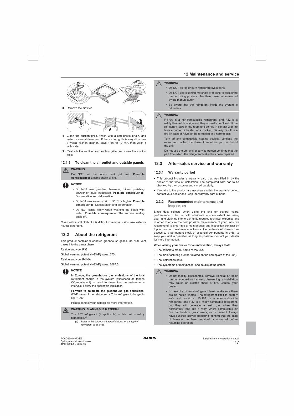
12 Maintenance and service
Installation and operation manual
17FCAG35~140AVEBSplit system air conditioners4P471224-1 – 2017.03
45°
1 2
3 Remove the air filter.
1
23
4 Clean the suction grille. Wash with a soft bristle brush, andwater or neutral detergent. If the suction grille is very dirty, usea typical kitchen cleaner, leave it on for 10 min, then wash itwith water.
5 Reattach the air filter and suction grille, and close the suctiongrille.
12.1.3 To clean the air outlet and outside panels
WARNING
Do NOT let the indoor unit get wet. Possibleconsequence: Electric shock or fire.
NOTICE
▪ Do NOT use gasoline, benzene, thinner polishingpowder or liquid insecticide. Possible consequence:Discoloration and deformation.
▪ Do NOT use water or air of 50°C or higher. Possibleconsequence: Discoloration and deformation.
▪ Do NOT scrub firmly when washing the blade withwater. Possible consequence: The surface sealingpeels off.
Clean with a soft cloth. If it is difficult to remove stains, use water orneutral detergent.
12.2 About the refrigerantThis product contains fluorinated greenhouse gases. Do NOT ventgases into the atmosphere.
Refrigerant type: R32
Global warming potential (GWP) value: 675
Refrigerant type: R410A
Global warming potential (GWP) value: 2087.5
NOTICE
In Europe, the greenhouse gas emissions of the totalrefrigerant charge in the system (expressed as tonnesCO2-equivalent) is used to determine the maintenanceintervals. Follow the applicable legislation.
Formula to calculate the greenhouse gas emissions:GWP value of the refrigerant × Total refrigerant charge [inkg] / 1000
Please contact your installer for more information.
WARNING: FLAMMABLE MATERIAL
The R32 refrigerant (if applicable) in this unit is mildlyflammable.(a)
(a) Refer to the outdoor unit specifications for the type ofrefrigerant to be used.
WARNING
▪ Do NOT pierce or burn refrigerant cycle parts.
▪ Do NOT use cleaning materials or means to acceleratethe defrosting process other than those recommendedby the manufacturer.
▪ Be aware that the refrigerant inside the system isodourless.
WARNING
R410A is a non-combustible refrigerant, and R32 is amildly flammable refrigerant; they normally don’t leak. If therefrigerant leaks in the room and comes in contact with firefrom a burner, a heater, or a cooker, this may result in afire (in case of R32), or the formation of a harmful gas.
Turn off any combustible heating devices, ventilate theroom, and contact the dealer from where you purchasedthe unit.
Do not use the unit until a service person confirms that thepart from which the refrigerant leaked has been repaired.
12.3 After-sales service and warranty
12.3.1 Warranty period▪ This product includes a warranty card that was filled in by the
dealer at the time of installation. The completed card has to bechecked by the customer and stored carefully.
▪ If repairs to the product are necessary within the warranty period,contact your dealer and keep the warranty card at hand.
12.3.2 Recommended maintenance andinspection
Since dust collects when using the unit for several years,performance of the unit will deteriorate to some extent. As takingapart and cleaning interiors of units requires technical expertise andin order to ensure the best possible maintenance of your units, werecommend to enter into a maintenance and inspection contract ontop of normal maintenance activities. Our network of dealers hasaccess to a permanent stock of essential components in order tokeep your unit in operation as long as possible. Contact your dealerfor more information.
When asking your dealer for an intervention, always state:▪ The complete model name of the unit.
▪ The manufacturing number (stated on the nameplate of the unit).
▪ The installation date.
▪ The symptoms or malfunction, and details of the defect.
WARNING
▪ Do not modify, disassemble, remove, reinstall or repairthe unit yourself as incorrect dismantling or installationmay cause an electric shock or fire. Contact yourdealer.
▪ In case of accidental refrigerant leaks, make sure thereare no naked flames. The refrigerant itself is entirelysafe and non-toxic. R410A is a non-combustiblerefrigerant, and R32 is a mildly flammable refrigerant,but they will generate a toxic gas when theyaccidentally leak into a room where combustible airfrom fan heaters, gas cookers, etc. is present. Alwayshave qualified service personnel confirm that the pointof leakage has been repaired or corrected beforeresuming operation.

13 Troubleshooting
Installation and operation manual
18FCAG35~140AVEB
Split system air conditioners4P471224-1 – 2017.03
13 TroubleshootingIf one of the following malfunctions occur, take the measures shownbelow and contact your dealer.
WARNING
Stop operation and shut off the power if anythingunusual occurs (burning smells etc.).
Leaving the unit running under such circumstances maycause breakage, electric shock or fire. Contact your dealer.
The system must be repaired by a qualified service person:
Malfunction MeasureIf a safety device such as a fuse, abreaker or an earth leakage breakerfrequently actuates or the ON/OFFswitch does not properly work.
Turn off the main powerswitch.
If water leaks from the unit. Stop the operation.The operation switch does not workwell.
Turn off the power.
If the user interface display indicates theunit number, the operation lamp flashesand the malfunction code appears.
Notify your installer andreport the malfunctioncode.
If the system does not properly operate except for the abovementioned cases and none of the above mentioned malfunctions isevident, investigate the system according to the followingprocedures.
Malfunction MeasureIf the system does notoperate at all.
▪ Check if there is no power failure. Waituntil power is restored. If power failureoccurs during operation, the systemautomatically restarts immediately afterpower is restored.
▪ Check if no fuse has blown or breaker isactivated. Change the fuse or reset thebreaker if necessary.
The system operatesbut cooling or heatingis insufficient.
▪ Check if air inlet or outlet of outdoor orindoor unit is not blocked by obstacles.Remove any obstacles and make surethe air can flow freely.
▪ Check if the air filter is not clogged (see"12.1.1 To clean the air filter" onpage 16).
▪ Check the temperature setting.
▪ Check the fan speed setting on your userinterface.
▪ Check for open doors or windows. Closedoors and windows to prevent wind fromcoming in.
▪ Check if there are too many occupants inthe room during cooling operation. Checkif the heat source of the room isexcessive.
▪ Check if direct sunlight enters the room.Use curtains or blinds.
▪ Check if the air flow angle is proper.
If after checking all above items, it is impossible to fix the problemyourself, contact your installer and state the symptoms, the completemodel name of the unit (with manufacturing number if possible) andthe installation date (possibly listed on the warranty card).
13.1 Symptoms that are NOT systemmalfunctions
The following symptoms are NOT system malfunctions:
13.1.1 Symptom: The system does not operate▪ The air conditioner does not start immediately after the ON/OFF
button on the user interface is pressed. If the operation lamplights, the system is in normal condition. To prevent overloading ofthe compressor motor, the air conditioner starts 5 minutes after itis turned ON again in case it was turned OFF just before. Thesame starting delay occurs after the operation mode selectorbutton was used.
▪ If "Under Centralized Control" is displayed on the user interface,pressing the operation button causes the display to blink for a fewseconds. The blinking display indicates that the user interfacecannot be used.
▪ The system does not start immediately after the power supply isturned on. Wait one minute until the micro computer is preparedfor operation.
13.1.2 Symptom: The fan strength does notcorrespond to the setting
The fan speed does not change even if the fan speed adjustmentbutton in pressed. During heating operation, when the roomtemperature reaches the set temperature, the outdoor unit goes offand the indoor unit changes to whisper fan speed. This is to preventcold air blowing directly on occupants of the room. The fan speedwill not change if the button is pressed.
13.1.3 Symptom: The fan direction does notcorrespond to the setting
The fan direction does not correspond with the user interfacedisplay. The fan direction does not swing. This is because the unit isbeing controlled by the micro computer.
13.1.4 Symptom: White mist comes out of a unit(Indoor unit)
▪ When humidity is high during cooling operation. If the interior of anindoor unit is extremely contaminated, the temperature distributioninside a room becomes uneven. It is necessary to clean theinterior of the indoor unit. Ask your dealer for details on cleaningthe unit. This operation requires a qualified service person.
▪ Immediately after the cooling operation stops and if the roomtemperature and humidity are low. This is because warmrefrigerant gas flows back into the indoor unit and generatessteam.
13.1.5 Symptom: White mist comes out of a unit(Indoor unit, outdoor unit)
When the system is changed over to heating operation after defrostoperation. Moisture generated by defrost becomes steam and isexhausted.
13.1.6 Symptom: The user interface displayreads "U4" or "U5" and stops, but thenrestarts after a few minutes
This is because the user interface is intercepting noise from electricappliances other than the air conditioner. The noise preventscommunication between the units, causing them to stop. Operationautomatically restarts when the noise ceases.
14 Relocation
Installation and operation manual
19FCAG35~140AVEBSplit system air conditioners4P471224-1 – 2017.03
13.1.7 Symptom: Noise of air conditioners(Indoor unit)
▪ A "zeen" sound is heard immediately after the power supply isturned on. The electronic expansion valve inside an indoor unitstarts working and makes the noise. Its volume will reduce inabout one minute.
▪ A continuous low "shah" sound is heard when the system is incooling operation or at a stop. When the drain pump is inoperation, this noise is heard.
▪ A "pishi-pishi" squeaking sound is heard when the system stopsafter heating operation. Expansion and contraction of plastic partscaused by temperature change make this noise.
13.1.8 Symptom: Noise of air conditioners(Indoor unit, outdoor unit)
▪ A continuous low hissing sound is heard when the system is incooling or defrost operation. This is the sound of refrigerant gasflowing through both indoor and outdoor units.
▪ A hissing sound which is heard at the start or immediately afterstopping operation or defrost operation. This is the noise ofrefrigerant caused by flow stop or flow change.
13.1.9 Symptom: Noise of air conditioners(Outdoor unit)
When the tone of operating noise changes. This noise is caused bythe change of frequency.
13.1.10 Symptom: Dust comes out of the unitWhen the unit is used for the first time in a long time. This isbecause dust has gotten into the unit.
13.1.11 Symptom: The units can give off odoursThe unit can absorb the smell of rooms, furniture, cigarettes, etc.,and then emit it again.
13.1.12 Symptom: The outdoor unit fan does notspin
During operation. The speed of the fan is controlled in order tooptimise product operation.
13.1.13 Symptom: The display shows "88"This is the case immediately after the main power supply switch isturned on and means that the user interface is in normal condition.This continues for 1 minute.
13.1.14 Symptom: The compressor in the outdoorunit does not stop after a short heatingoperation
This is to prevent refrigerant from remaining in the compressor. Theunit will stop after 5 to 10 minutes.
14 RelocationContact your dealer for removing and reinstalling the total unit.Moving units requires technical expertise.
15 DisposalThis unit uses hydrofluorocarbon. Contact your dealer whendiscarding this unit.
Do not try to dismantle the system yourself: the dismantling of thesystem, treatment of the refrigerant, of oil and of other parts mustcomply with applicable legislation. Units must be treated at aspecialised treatment facility for reuse, recycling and recovery.
4P471224-1 2017.03
Cop
yrig
ht 2
017
Dai
kin