INSTALLATION AND OPERATION MANUAL - Nortec …€¦ · For Interfacing Nortec Products: NH-EL, GS,...
46
Humidification and Evaporative Cooling INSTALLATION AND OPERATION MANUAL ProtoCessor FPC-ED2 and ProtoCessor FPC-ED4 Nortec LINKS 2587516_A_EN_1609
Transcript of INSTALLATION AND OPERATION MANUAL - Nortec …€¦ · For Interfacing Nortec Products: NH-EL, GS,...
Humidification and Evaporative Cooling
INSTALLATION AND OPERATION MANUAL ProtoCessor FPC-ED2 and ProtoCessor FPC-ED4 Nortec LINKS
2587516_A
_E
N_1609

For Interfacing Nortec Products: NH-EL, GS, EL, RS To Building Automation Systems: BACnet MS/TP, BACnet/IP, Metasys N2 and LonWorks
Technical Support
Thank you for purchasing the ProtoCessor for Nortec. Please call Nortec for Technical support of the ProtoCessor product. Sierra Monitor Corporation does not provide direct support. If Nortec needs to escalate the concern, they will contact Sierra Monitor Corporation for assistance. Support Contact Information: U.S.A. Nortec Humidity Inc. 2700 90th Street Sturtevant, WI 53177 USA Canada Nortec Humidity Ltd. 2740 Fenton Rd Ottawa, Ontario K1T 3T7 Nortec Service:
1.866.NORTEC1 Fax:
1.613.822.9764 Email: [email protected] Website: www.Humidity.com APPLICABILITY & EFFECTIVITY
Explains ProtoCessor FPC-ED2 hardware and how to install it.
The instructions are effective for the above as of July 2016.
Document Revision: 2.H Web Configurator
Template Revision: 60
INSTALLATION AND OPERATION MANUAL
Nortec LINKS ProtoCessor FPC-ED2 and ProtoCessor FPC-ED4 2587516_A_EN_1609
Thank you for choosing Nortec
Installation date (DD/MM/YYYY):
Commissioning date (DD/MM/YYYY):
Site:
Model:
Serial number:
Manufacturer
Nortec Humidity Ltd. 2740 Fenton Road, Ottawa, ON, Canada K1T 3T7 Tel. 1.866.NORTEC1, Fax 613.822.7964 [email protected], www.humidity.com
Proprietary Notice
This document and the information disclosed herein are proprietary data of Nortec Humidity Ltd. Neither this document, nor the information contained herein shall be reproduced, used, or disclosed to others without the written authorization of Nortec Humidity Ltd., except to the extent required for installation, operation or maintenance of the customer's equipment.
Liability Notice
Nortec Humidity Ltd. does not accept any liability due to incorrect installation, maintenance or operation of the equipment, or due to the use of parts/components/equipment that are not authorized by Nortec Humidity Ltd.
Copyright Notice
Copyright 2016, Nortec Humidity Ltd, All rights reserved.
Technical modification rights reserved.
Nortec LINKS 2587516_A_EN I V
Contents
1 Quick Start Guide ........................................................................................................ 7
2 Certifications ................................................................................................................ 8
3 Introduction .................................................................................................................. 9 3.1 ProtoCessor Gateway ................................................................................................... 9
4 Setup for ProtoCessor ...............................................................................................10 4.1 Record Identification Data ............................................................................................10 4.2 Point Count Capacity and Registers per Device ...........................................................10 4.3 Configuring Device Communications ............................................................................10 4.3.1 Input COM Settings for Device with an Inserted ProtoCessor ..................................10 4.3.2 Set Modbus RTU Node-ID for the Device ................................................................11
5 Interfacing ProtoCessor to Device ............................................................................12 5.1 ProtoCessor FPC-ED2 and FPC-ED4 Mounted onto Board .........................................12 5.2 ProtoCessor FPC-ED2 and FPC-ED4 Showing Connection Ports................................13 5.3 BACnet MS/TP or Metasys N2: Wiring Field Port to RS-485 Network ..........................14 5.4 LonWorks (FPC-ED4): Wiring Field Port to LonWorks Network ....................................14
6 Use ProtoCessor Web Configurator to Setup the Gateway .....................................15 6.1 Connect the PC to ProtoCessor via the Ethernet Port ..................................................15 6.2 Connecting to ProtoCessor Web Configurator ..............................................................16 6.3 Selecting Profiles for Device Connected to ProtoCessor ..............................................16 6.4 BACnet/IP Setting IP Address for Field Network ..........................................................19 6.5 Select Field Protocol ....................................................................................................22 6.5.1 BACnet MS/TP Configuration ..................................................................................22 6.5.2 BACnet/IP Configuration .........................................................................................23 6.5.3 Metasys N2 Configuration .......................................................................................24
7 BACnet MS/TP and BACnet/IP: Setting Node_Offset to Assign Specific Device Instances ...........................................................................................26
8 How to Start the Installation Over: Clearing Profiles ...............................................27
9 LonWorks (FPC-ED4): Commissioning ProtoCessor on a lonworks Network .......28 9.1 Commissioning ProtoCessor FPC-ED4 on a LonWorks Network .................................28 9.1.1 Instructions to Download XIF File from ProtoCessor FPC-ED4 Using Browser........28
A Troubleshooting ........................................................................................................... i A.1 Lost or Incorrect IP Address ............................................................................................ i A.2 Viewing Diagnostic information ...................................................................................... ii A.3 Check Wiring and Settings ............................................................................................. ii A.4 LED Diagnostics for Communications Between ProtoCessor and Device ..................... iii A.5 Take Diagnostic Capture With the FieldServer Utilities .................................................. iv
VI | 2587516_A_EN_1609 Nortec LINKS
A.6 Update Firmware .......................................................................................................... vii A.7 BACnet: Setting Network_Number for more than one ProtoCessor on Subnet ............. vii A.8 Securing the ProtoCessor with Passwords .................................................................. viii
B Vendor Information - Nortec ..................................................................................... viii B.1 NHEL Modbus RTU Mappings to BACnet, Metasys N2 and LonWorks ....................... viii B.2 GS Modbus RTU Mappings to BACnet, Metasys N2 and LonWorks ............................. ix B.3 EL Modbus RTU Mappings to BACnet, Metasys N2 and LonWorks ............................... x B.4 EL Modbus RTU Mappings to BACnet, Metasys N2 and LonWorks .............................. xi
C Reference ................................................................................................................... xiii C.1 Specifications .............................................................................................................. xiii C.2 Compliance with UL Regulations ................................................................................. xiii
Nortec LINKS 587516_A_EN_1609 I 7
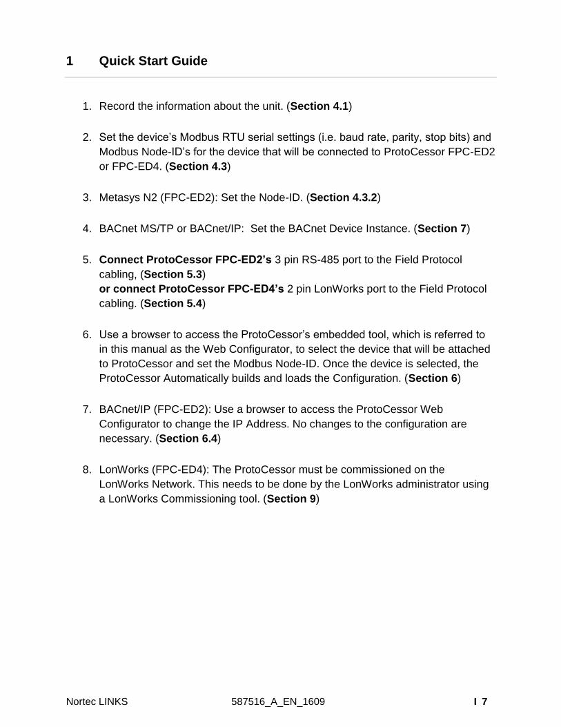
1 Quick Start Guide
1. Record the information about the unit. (Section 4.1)
2. Set the device’s Modbus RTU serial settings (i.e. baud rate, parity, stop bits) and
Modbus Node-ID’s for the device that will be connected to ProtoCessor FPC-ED2
or FPC-ED4. (Section 4.3)
3. Metasys N2 (FPC-ED2): Set the Node-ID. (Section 4.3.2)
4. BACnet MS/TP or BACnet/IP: Set the BACnet Device Instance. (Section 7)
5. Connect ProtoCessor FPC-ED2’s 3 pin RS-485 port to the Field Protocol
cabling, (Section 5.3)
or connect ProtoCessor FPC-ED4’s 2 pin LonWorks port to the Field Protocol
cabling. (Section 5.4)
6. Use a browser to access the ProtoCessor’s embedded tool, which is referred to
in this manual as the Web Configurator, to select the device that will be attached
to ProtoCessor and set the Modbus Node-ID. Once the device is selected, the
ProtoCessor Automatically builds and loads the Configuration. (Section 6)
7. BACnet/IP (FPC-ED2): Use a browser to access the ProtoCessor Web
Configurator to change the IP Address. No changes to the configuration are
necessary. (Section 6.4)
8. LonWorks (FPC-ED4): The ProtoCessor must be commissioned on the
LonWorks Network. This needs to be done by the LonWorks administrator using
a LonWorks Commissioning tool. (Section 9)
8 | 2587516_A_EN_1609 Nortec LINKS
2 Certifications
BTL MARK – BACNET TESTING LABORATORY
LONMARK CERTIFICATION
The BTL Mark on ProtoCessor is a symbol that indicates that a product
has passed a series of rigorous tests conducted by an independent
laboratory which verifies that the product correctly implements the
BACnet features claimed in the listing. The mark is a symbol of a high-
quality BACnet product.
Go to http://www.BACnetInternational.net/btl/ for more information about
the BACnet Testing Laboratory. Click here for BACnet PIC Statement.
LonMark International is the recognized authority for certification,
education, and promotion of interoperability standards for the
benefit of manufacturers, integrators and end users. LonMark
International has developed extensive product certification
standards and tests to provide the integrator and user with
confidence that products from multiple manufacturers utilizing
LonMark devices work together. Sierra Monitor has more LonMark
Certified gateways than any other gateway manufacturer,
including the ProtoCessor, ProtoCarrier and ProtoCessor for OEM
applications and the full featured, configurable gateways.
Nortec LINKS 587516_A_EN_1609 I 9
3 Introduction
3.1 ProtoCessor Gateway
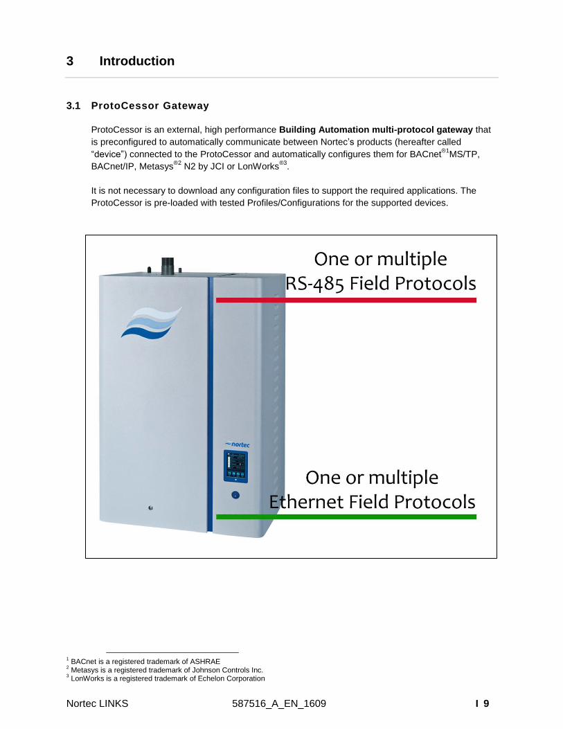
ProtoCessor is an external, high performance Building Automation multi-protocol gateway that
is preconfigured to automatically communicate between Nortec’s products (hereafter called
“device”) connected to the ProtoCessor and automatically configures them for BACnet®1
MS/TP,
BACnet/IP, Metasys®2
N2 by JCI or LonWorks®3
.
It is not necessary to download any configuration files to support the required applications. The
ProtoCessor is pre-loaded with tested Profiles/Configurations for the supported devices.
1 BACnet is a registered trademark of ASHRAE
2 Metasys is a registered trademark of Johnson Controls Inc.
3 LonWorks is a registered trademark of Echelon Corporation
10 | 2587516_A_EN_1609 Nortec LINKS
4 Setup for ProtoCessor
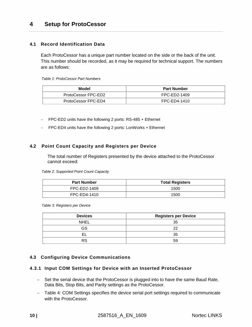
4.1 Record Identification Data
Each ProtoCessor has a unique part number located on the side or the back of the unit.
This number should be recorded, as it may be required for technical support. The numbers
are as follows:
Table 1: ProtoCessor Part Numbers
Model Part Number
ProtoCessor FPC-ED2 FPC-ED2-1409
ProtoCessor FPC-ED4 FPC-ED4-1410
FPC-ED2 units have the following 2 ports: RS-485 + Ethernet
FPC-ED4 units have the following 2 ports: LonWorks + Ethernet
4.2 Point Count Capacity and Registers per Device
The total number of Registers presented by the device attached to the ProtoCessor cannot exceed:
Table 2: Supported Point Count Capacity
Part Number Total Registers
FPC-ED2-1409 1500
FPC-ED4-1410 1500
Table 3: Registers per Device
Devices Registers per Device
NHEL 35
GS 22
EL 35
RS 59
4.3 Configuring Device Communications
4.3.1 Input COM Settings for Device with an Inserted ProtoCessor
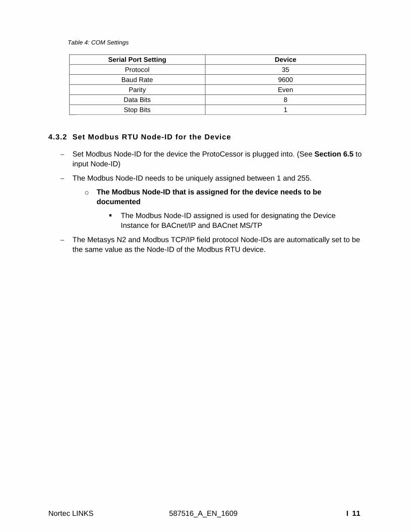
Set the serial device that the ProtoCessor is plugged into to have the same Baud Rate, Data Bits, Stop Bits, and Parity settings as the ProtoCessor.
Table 4: COM Settings specifies the device serial port settings required to communicate
with the ProtoCessor.
Nortec LINKS 587516_A_EN_1609 I 11
Table 4: COM Settings
Serial Port Setting Device
Protocol 35
Baud Rate 9600
Parity Even
Data Bits 8
Stop Bits 1
4.3.2 Set Modbus RTU Node-ID for the Device
Set Modbus Node-ID for the device the ProtoCessor is plugged into. (See Section 6.5 to
input Node-ID)
The Modbus Node-ID needs to be uniquely assigned between 1 and 255.
o The Modbus Node-ID that is assigned for the device needs to be
documented
The Modbus Node-ID assigned is used for designating the Device
Instance for BACnet/IP and BACnet MS/TP
The Metasys N2 and Modbus TCP/IP field protocol Node-IDs are automatically set to be
the same value as the Node-ID of the Modbus RTU device.
12 | 2587516_A_EN_1609 Nortec LINKS
5 Interfacing ProtoCessor to Device
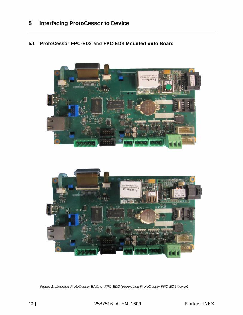
5.1 ProtoCessor FPC-ED2 and FPC-ED4 Mounted onto Board
Figure 1: Mounted ProtoCessor BACnet FPC-ED2 (upper) and ProtoCessor FPC-ED4 (lower)
Nortec LINKS 587516_A_EN_1609 I 13
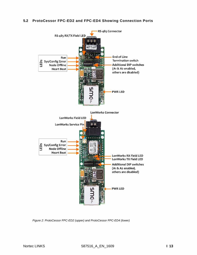
5.2 ProtoCessor FPC-ED2 and FPC-ED4 Showing Connection Ports
Figure 2: ProtoCessor FPC-ED2 (upper) and ProtoCessor FPC-ED4 (lower)
14 | 2587516_A_EN_1609 Nortec LINKS
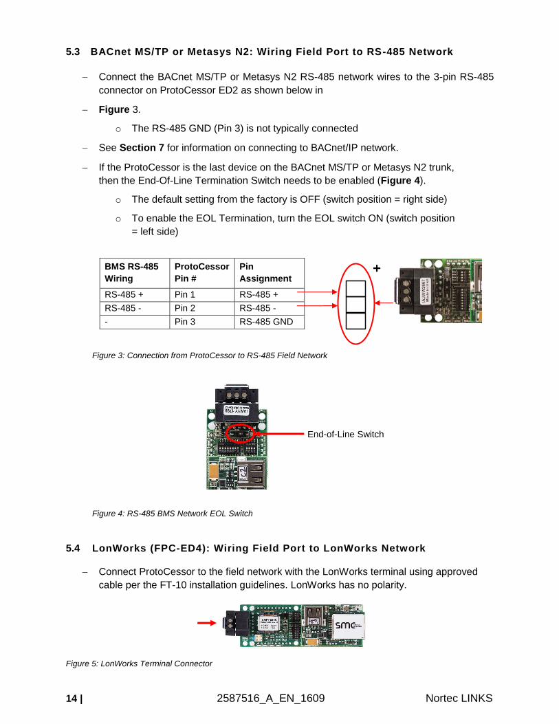
5.3 BACnet MS/TP or Metasys N2: Wiring Field Port to RS-485 Network
Connect the BACnet MS/TP or Metasys N2 RS-485 network wires to the 3-pin RS-485
connector on ProtoCessor ED2 as shown below in
Figure 3.
o The RS-485 GND (Pin 3) is not typically connected
See Section 7 for information on connecting to BACnet/IP network.
If the ProtoCessor is the last device on the BACnet MS/TP or Metasys N2 trunk,
then the End-Of-Line Termination Switch needs to be enabled (Figure 4).
o The default setting from the factory is OFF (switch position = right side)
o To enable the EOL Termination, turn the EOL switch ON (switch position
= left side)
Figure 3: Connection from ProtoCessor to RS-485 Field Network
Figure 4: RS-485 BMS Network EOL Switch
5.4 LonWorks (FPC-ED4): Wiring Field Port to LonWorks Network
Connect ProtoCessor to the field network with the LonWorks terminal using approved
cable per the FT-10 installation guidelines. LonWorks has no polarity.
Figure 5: LonWorks Terminal Connector
BMS RS-485
Wiring
ProtoCessor
Pin #
Pin
Assignment
RS-485 + Pin 1 RS-485 +
RS-485 - Pin 2 RS-485 -
- Pin 3 RS-485 GND
+
End-of-Line Switch
Nortec LINKS 587516_A_EN_1609 I 15
6 Use ProtoCessor Web Configurator to Setup the Gateway
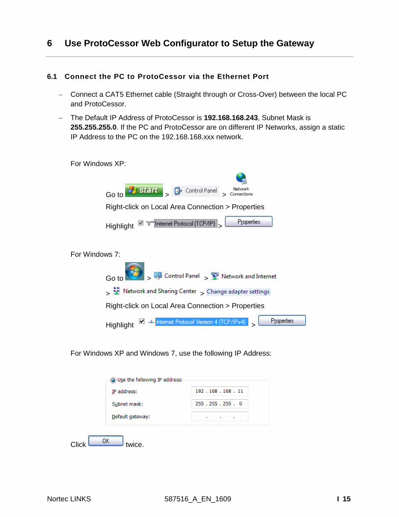
6.1 Connect the PC to ProtoCessor via the Ethernet Port
Connect a CAT5 Ethernet cable (Straight through or Cross-Over) between the local PC
and ProtoCessor.
The Default IP Address of ProtoCessor is 192.168.168.243, Subnet Mask is
255.255.255.0. If the PC and ProtoCessor are on different IP Networks, assign a static
IP Address to the PC on the 192.168.168.xxx network.
For Windows XP:
Go to > >
Right-click on Local Area Connection > Properties
Highlight >
For Windows 7:
Go to > >
> >
Right-click on Local Area Connection > Properties
Highlight >
For Windows XP and Windows 7, use the following IP Address:
Click twice.
16 | 2587516_A_EN_1609 Nortec LINKS
6.2 Connecting to ProtoCessor Web Configurator
After setting a local PC on the same subnet as the ProtoCessor (Section 6.1), open a
web browser on the PC and enter the IP Address of the ProtoCessor; the default
address is 192.168.168.243.
NOTE: If the IP Address of the ProtoCessor has been changed by previous
configuration, the assigned IP Address must be gathered from the network
administrator.
6.3 Selecting Profiles for Device Connected to ProtoCessor
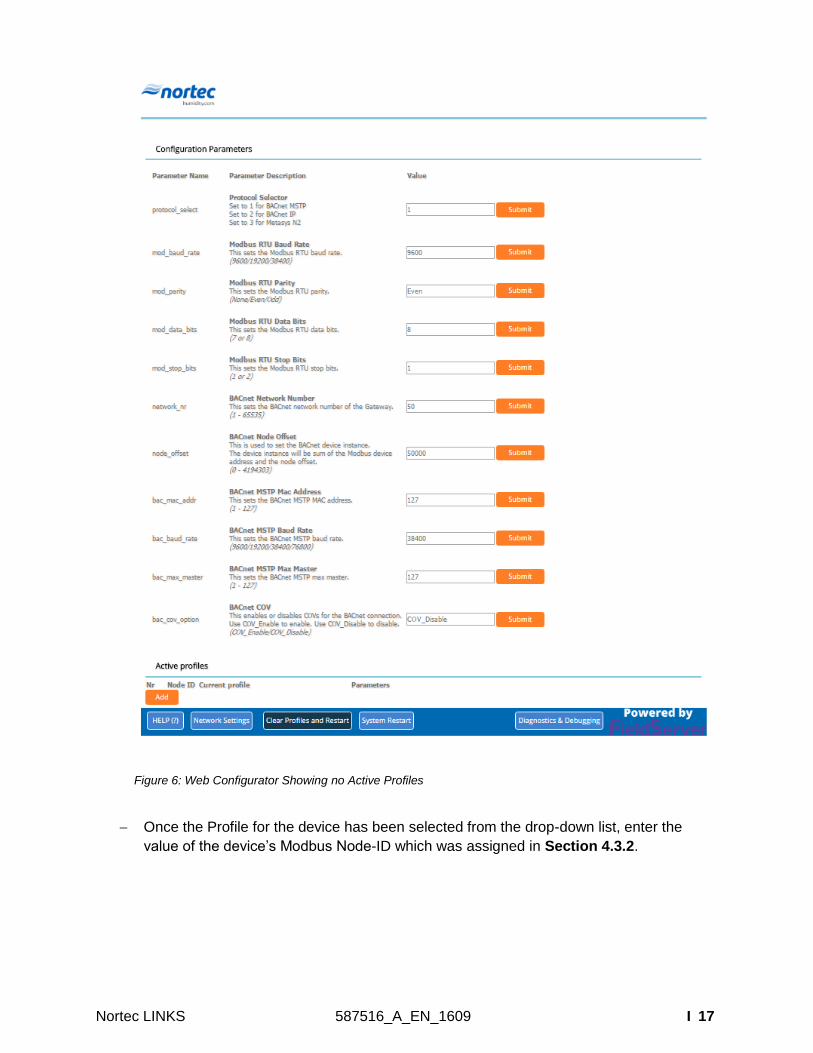
In the Web Configurator, the Active Profiles section is shown on the lower left side of the
screen.
The Active Profiles section lists the currently active device profiles, including previous
Web Configurator additions. This list will be empty for new installations, or after clearing
all configurations. (
Figure 6)
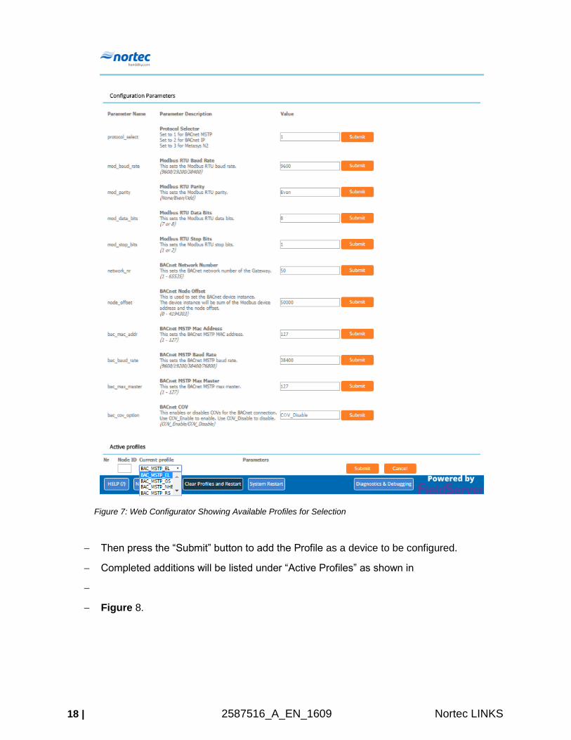
To add an active profile to support a device, click the ADD button under Active Profiles.
This will present a drop-down box underneath the Current Profile column that lists all the
available profiles. (
Figure 7)
For every device that is added, assign a unique Modbus Node-ID. This specification
must match the device’s network settings.
Nortec LINKS 587516_A_EN_1609 I 17
Figure 6: Web Configurator Showing no Active Profiles
Once the Profile for the device has been selected from the drop-down list, enter the
value of the device’s Modbus Node-ID which was assigned in Section 4.3.2.
18 | 2587516_A_EN_1609 Nortec LINKS
Figure 7: Web Configurator Showing Available Profiles for Selection
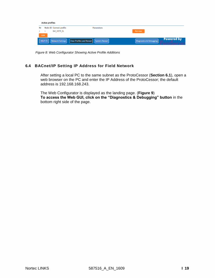
Then press the “Submit” button to add the Profile as a device to be configured.
Completed additions will be listed under “Active Profiles” as shown in
Figure 8.
Nortec LINKS 587516_A_EN_1609 I 19
Figure 8: Web Configurator Showing Active Profile Additions
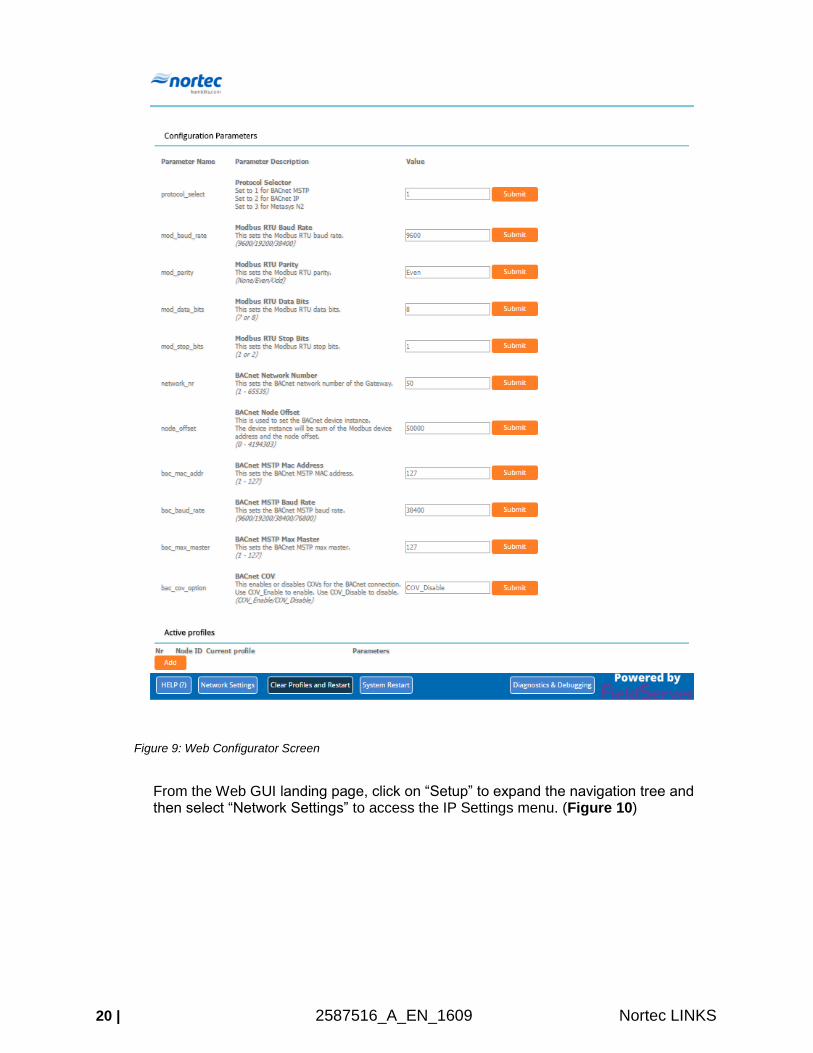
6.4 BACnet/IP Setting IP Address for Field Network
After setting a local PC to the same subnet as the ProtoCessor (Section 6.1), open a web browser on the PC and enter the IP Address of the ProtoCessor; the default address is 192.168.168.243. The Web Configurator is displayed as the landing page. (Figure 9) To access the Web GUI, click on the “Diagnostics & Debugging” button in the bottom right side of the page.
20 | 2587516_A_EN_1609 Nortec LINKS
Figure 9: Web Configurator Screen
From the Web GUI landing page, click on “Setup” to expand the navigation tree and then select “Network Settings” to access the IP Settings menu. (Figure 10)
Nortec LINKS 587516_A_EN_1609 I 21
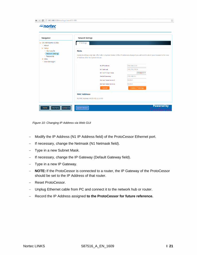
Figure 10: Changing IP Address via Web GUI
Modify the IP Address (N1 IP Address field) of the ProtoCessor Ethernet port.
If necessary, change the Netmask (N1 Netmask field).
Type in a new Subnet Mask.
If necessary, change the IP Gateway (Default Gateway field).
Type in a new IP Gateway.
NOTE: If the ProtoCessor is connected to a router, the IP Gateway of the ProtoCessor
should be set to the IP Address of that router.
Reset ProtoCessor.
Unplug Ethernet cable from PC and connect it to the network hub or router.
Record the IP Address assigned to the ProtoCessor for future reference.
22 | 2587516_A_EN_1609 Nortec LINKS
6.5 Select Field Protocol
For ED2 – Use the Protocol Selector by typing in the corresponding number next to the
desired protocol:
o BACnet MS/TP 1
o BACnet/IP 2
o Metasys N2 3
Then click “System Restart” to bring up options to configure the desired protocol.
For ED4 – There are no device details to be entered for this protocol combination.
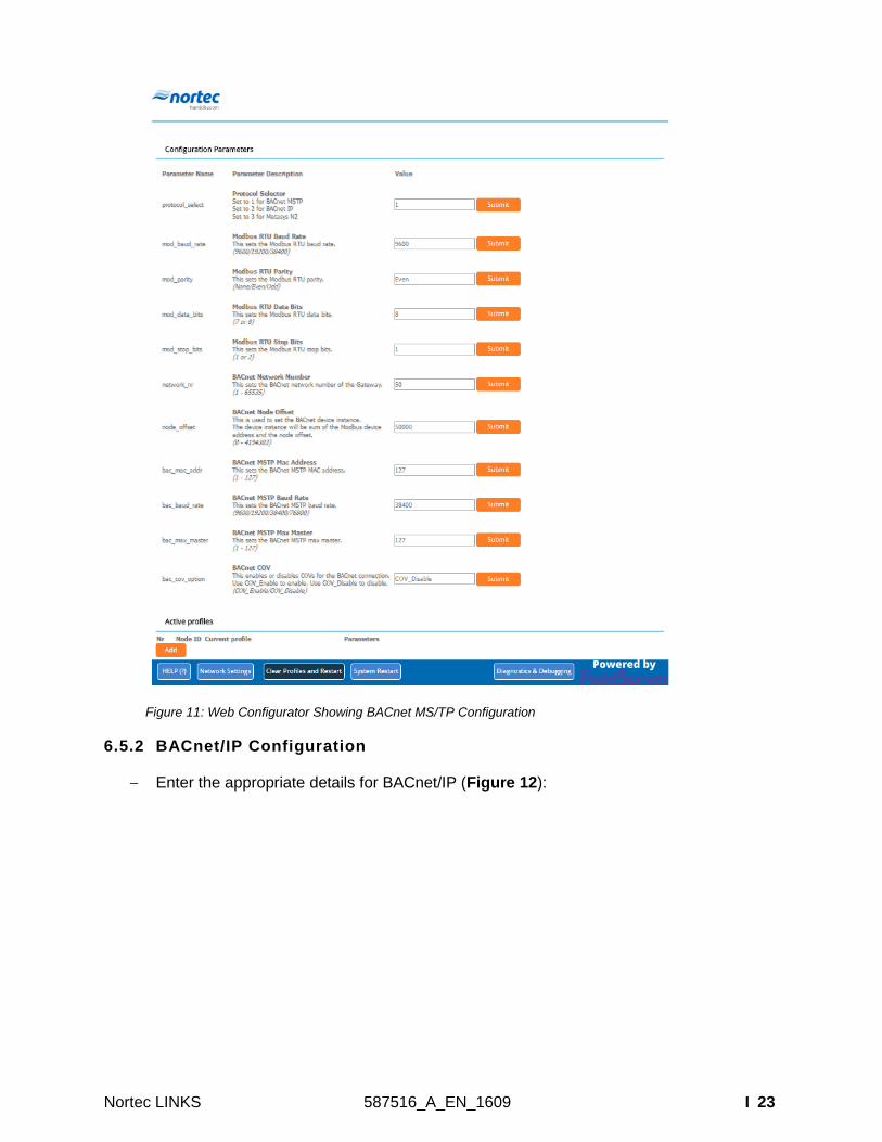
6.5.1 BACnet MS/TP Configuration
Enter the appropriate details for BACnet MS/TP (
Figure 11):
Nortec LINKS 587516_A_EN_1609 I 23
Figure 11: Web Configurator Showing BACnet MS/TP Configuration
6.5.2 BACnet/IP Configuration
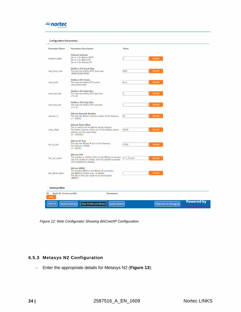
Enter the appropriate details for BACnet/IP (Figure 12):
24 | 2587516_A_EN_1609 Nortec LINKS
Figure 12: Web Configurator Showing BACnet/IP Configuration
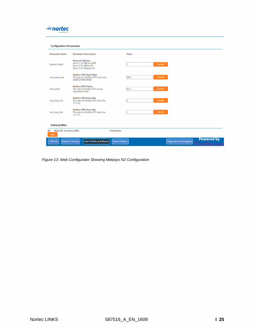
6.5.3 Metasys N2 Configuration
Enter the appropriate details for Metasys N2 (Figure 13):
Nortec LINKS 587516_A_EN_1609 I 25
Figure 13: Web Configurator Showing Metasys N2 Configuration
26 | 2587516_A_EN_1609 Nortec LINKS
7 BACnet MS/TP and BACnet/IP: Setting Node_Offset to Assign Specific Device Instances
After setting a local PC to the same subnet as the ProtoNode (Section 6.1), open a web
browser on the PC and enter the IP Address of the ProtoNode; the default address is
192.168.168.243.
o The Web Configurator will be displayed as the landing page. (
o
o Figure 11 or Figure 12)
The Node_Offset field shows the current value (default = 50,000).
o The values allowed for a BACnet Device Instance can range from 1 to 4,194,303.
To assign a specific Device Instance (or range), change the Node_Offset value
accordingly.
o Given that: Node_Offset + Modbus Node_ID = Device Instance
o Then: Node_Offset (required) = Device Instance (desired) – Modbus
Node_ID
For example, if the desired Device Instance for the device is 1,001:
o Device has a Modbus Node-ID of 1
o Node_Offset (required) = 1,001 – (Modbus Node_ID) = 1,001 – 1 = 1,000
NOTE: The Node_Offset value will be applied to the device.
o Device Instance will then be = 1,000 + Modbus Node_ID = 1,000 + 1 = 1,001
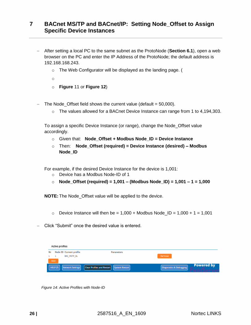
Click “Submit” once the desired value is entered.
Figure 14: Active Profiles with Node-ID
Nortec LINKS 587516_A_EN_1609 I 27
8 How to Start the Installation Over: Clearing Profiles
After setting a local PC to the same subnet as the ProtoCessor (Section 6.1), open a web browser on the PC and enter the IP Address of the ProtoCessor; the default address is 192.168.168.243.
If the IP Address of the ProtoCessor has been changed by previous configuration, the assigned IP Address must be gathered from the network administrator.
The Web Configurator is displayed as the landing page.
At the bottom-left of the page, click the “Clear Profiles and Restart” button.
Once restart is complete, all past profiles discovered and/or added via Web configurator are deleted. The unit can now be reinstalled.
28 | 2587516_A_EN_1609 Nortec LINKS
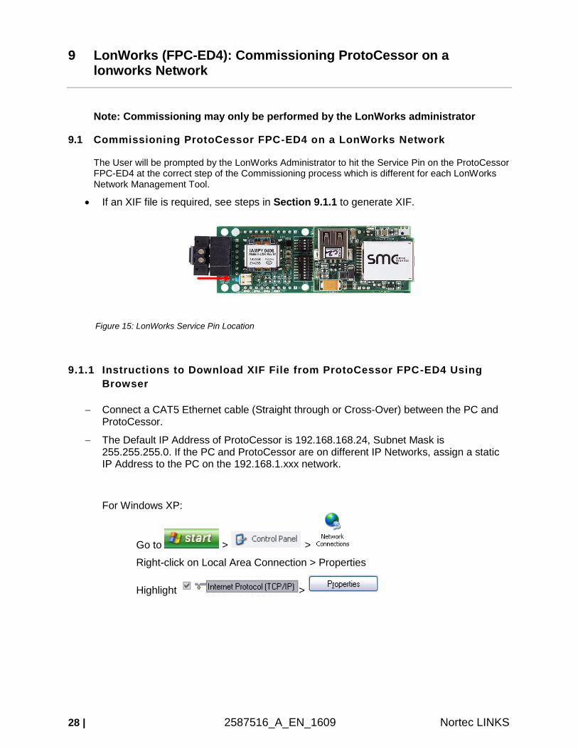
9 LonWorks (FPC-ED4): Commissioning ProtoCessor on a lonworks Network
Note: Commissioning may only be performed by the LonWorks administrator
9.1 Commissioning ProtoCessor FPC-ED4 on a LonWorks Network
The User will be prompted by the LonWorks Administrator to hit the Service Pin on the ProtoCessor FPC-ED4 at the correct step of the Commissioning process which is different for each LonWorks Network Management Tool.
If an XIF file is required, see steps in Section 9.1.1 to generate XIF.
Figure 15: LonWorks Service Pin Location
9.1.1 Instructions to Download XIF File from ProtoCessor FPC-ED4 Using
Browser
Connect a CAT5 Ethernet cable (Straight through or Cross-Over) between the PC and ProtoCessor.
The Default IP Address of ProtoCessor is 192.168.168.24, Subnet Mask is 255.255.255.0. If the PC and ProtoCessor are on different IP Networks, assign a static IP Address to the PC on the 192.168.1.xxx network.
For Windows XP:
Go to > >
Right-click on Local Area Connection > Properties
Highlight >
Nortec LINKS 587516_A_EN_1609 I 29
For Windows 7 or later:
Go to > >
> >
Right-click on Local Area Connection > Properties
Highlight >
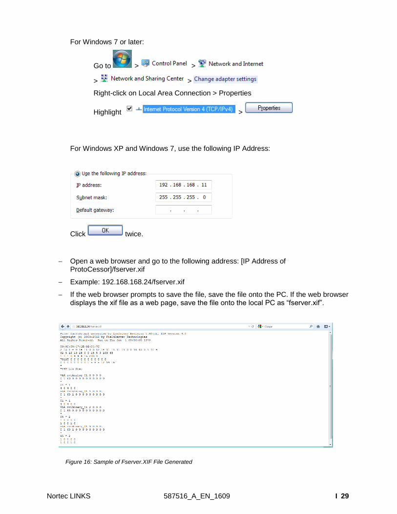
For Windows XP and Windows 7, use the following IP Address:
Click twice.
Open a web browser and go to the following address: [IP Address of ProtoCessor]/fserver.xif
Example: 192.168.168.24/fserver.xif
If the web browser prompts to save the file, save the file onto the PC. If the web browser displays the xif file as a web page, save the file onto the local PC as “fserver.xif”.
Figure 16: Sample of Fserver.XIF File Generated

30 | 2587516_A_EN_1609 Nortec LINKS
This page intentionally left blank
Nortec LINKS 587516_A_EN_1609 Appendix I i
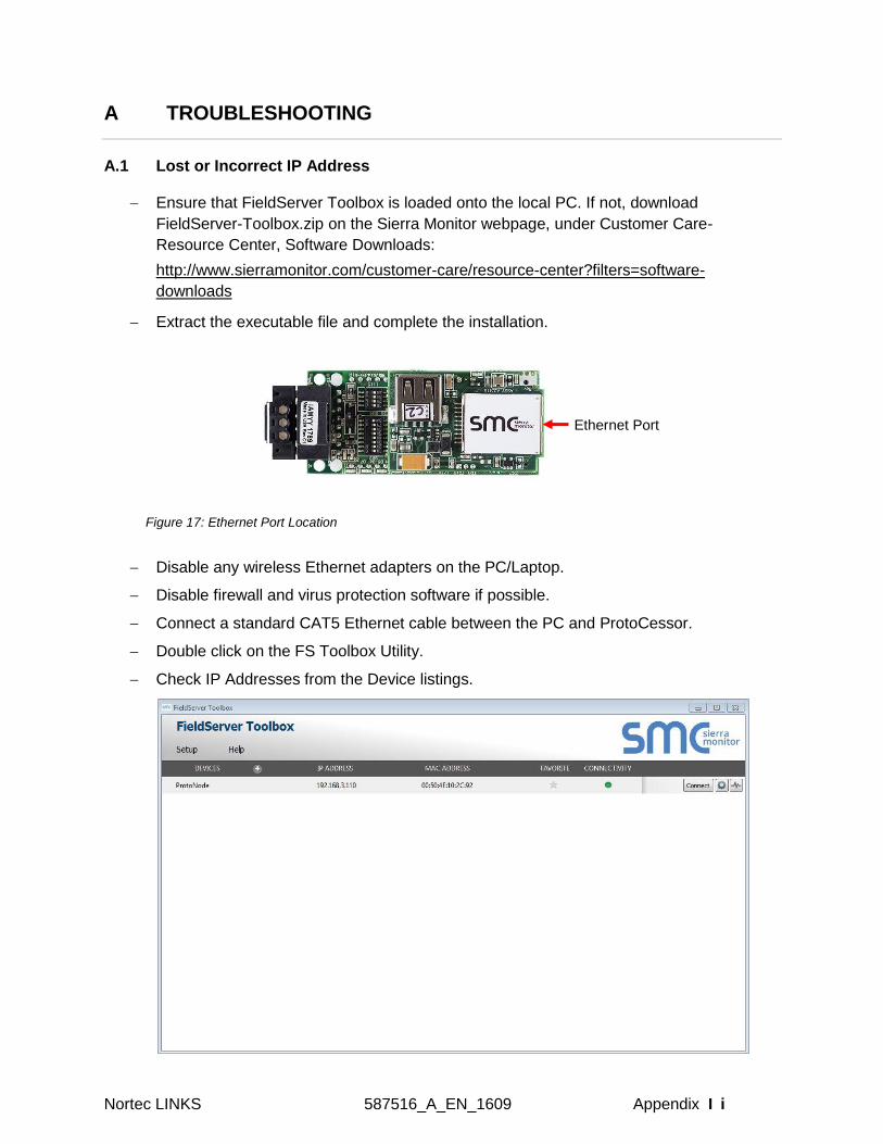
A TROUBLESHOOTING
A.1 Lost or Incorrect IP Address
Ensure that FieldServer Toolbox is loaded onto the local PC. If not, download
FieldServer-Toolbox.zip on the Sierra Monitor webpage, under Customer Care-
Resource Center, Software Downloads:
http://www.sierramonitor.com/customer-care/resource-center?filters=software-
downloads
Extract the executable file and complete the installation.
Figure 17: Ethernet Port Location
Disable any wireless Ethernet adapters on the PC/Laptop.
Disable firewall and virus protection software if possible.
Connect a standard CAT5 Ethernet cable between the PC and ProtoCessor.
Double click on the FS Toolbox Utility.
Check IP Addresses from the Device listings.
Ethernet Port
ii | Appendix 2587516_A_EN_1609 Nortec LINKS
Correct IP Address(es) by right clicking the settings icon and changing the IP
Address.
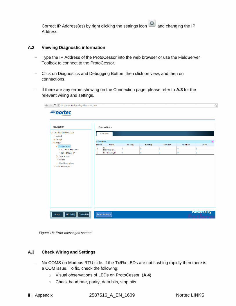
A.2 Viewing Diagnostic information
Type the IP Address of the ProtoCessor into the web browser or use the FieldServer
Toolbox to connect to the ProtoCessor.
Click on Diagnostics and Debugging Button, then click on view, and then on
connections.
If there are any errors showing on the Connection page, please refer to A.3 for the
relevant wiring and settings.
Figure 18: Error messages screen
A.3 Check Wiring and Settings
No COMS on Modbus RTU side. If the Tx/Rx LEDs are not flashing rapidly then there is
a COM issue. To fix, check the following:
o Visual observations of LEDs on ProtoCessor (A.4)
o Check baud rate, parity, data bits, stop bits
Nortec LINKS 587516_A_EN_1609 Appendix I iii
o Check device address
o Verify wiring
Field COM problems:
o Visual observations of LEDs on ProtoCessor (A.4)
o Check dipswitch settings (using correct baud rate and device instance)
o Verify IP Address setting
o Verify wiring
NOTE: If the problem persists, a Diagnostic Capture needs to be taken and sent to
support. (A.5)
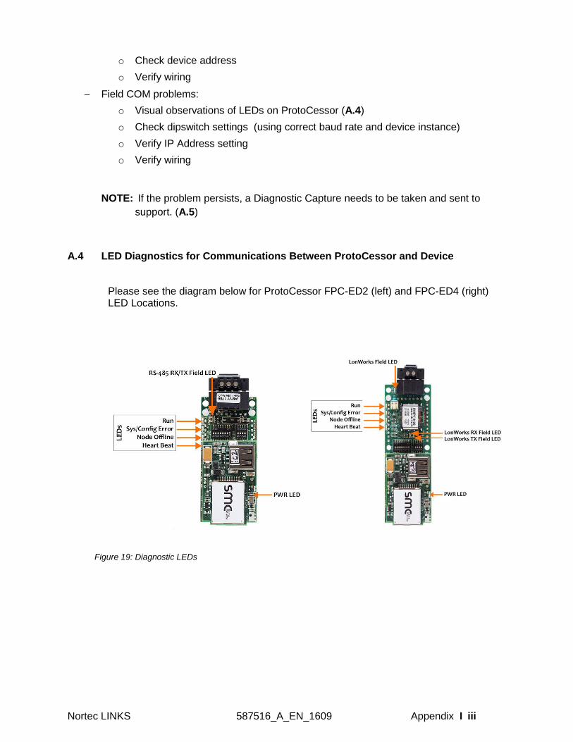
A.4 LED Diagnostics for Communications Between ProtoCessor and Device
Please see the diagram below for ProtoCessor FPC-ED2 (left) and FPC-ED4 (right) LED Locations.
Figure 19: Diagnostic LEDs
iv | Appendix 2587516_A_EN_1609 Nortec LINKS
Table 5 :Diagnostic LEDs
Tag Description
Run The Run LED will start flashing 20 seconds after power indicating normal operation. The Heat Beat LED has the same functionality but flashes more rapidly.
Sys/Config Error
The Sys/Config Error LED will go on solid 15 seconds after power up. It will turn off after 5 seconds. A steady red light will indicate there is a system error on ProtoCessor. If this occurs, immediately report the related “system error” shown in the error screen of the GUI interface to Sierra Monitor Corporation for evaluation.
Node Offline
The Node Offline LED will turn on and stay solid if there is no communication with the device.
RX The RX LED will flash when a message is received on the field port.
TX The TX LED will flash when a message is sent on the field port.
PWR This is the power light and should show steady green at all times when ProtoCessor is powered.
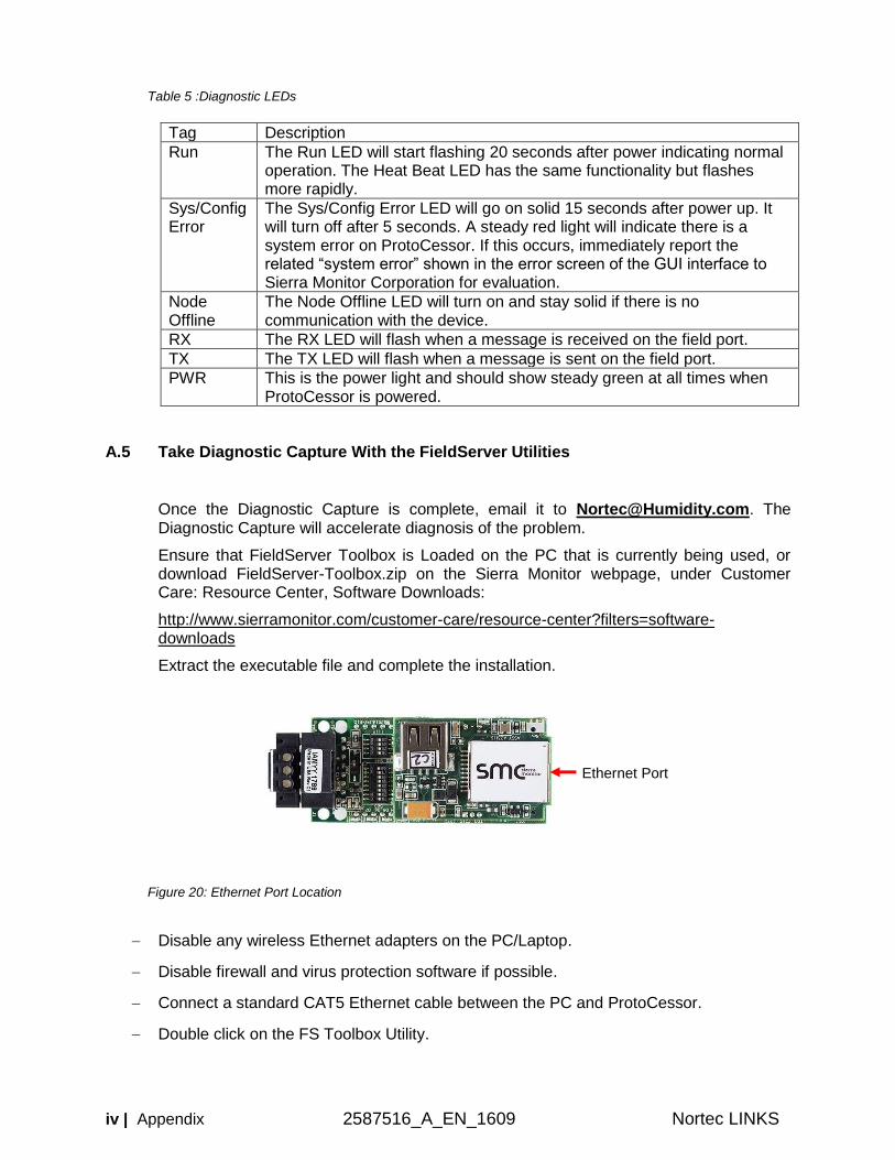
A.5 Take Diagnostic Capture With the FieldServer Utilities
Once the Diagnostic Capture is complete, email it to [email protected]. The Diagnostic Capture will accelerate diagnosis of the problem.
Ensure that FieldServer Toolbox is Loaded on the PC that is currently being used, or download FieldServer-Toolbox.zip on the Sierra Monitor webpage, under Customer Care: Resource Center, Software Downloads:
http://www.sierramonitor.com/customer-care/resource-center?filters=software-downloads
Extract the executable file and complete the installation.
Figure 20: Ethernet Port Location
Disable any wireless Ethernet adapters on the PC/Laptop.
Disable firewall and virus protection software if possible.
Connect a standard CAT5 Ethernet cable between the PC and ProtoCessor.
Double click on the FS Toolbox Utility.
Ethernet Port
Nortec LINKS 587516_A_EN_1609 Appendix I v
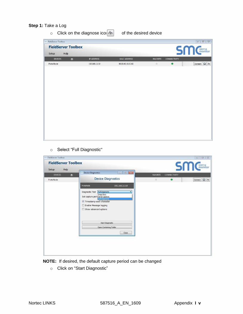
Step 1: Take a Log
o Click on the diagnose icon of the desired device
o Select “Full Diagnostic"
NOTE: If desired, the default capture period can be changed
o Click on “Start Diagnostic”
vi | Appendix 2587516_A_EN_1609 Nortec LINKS
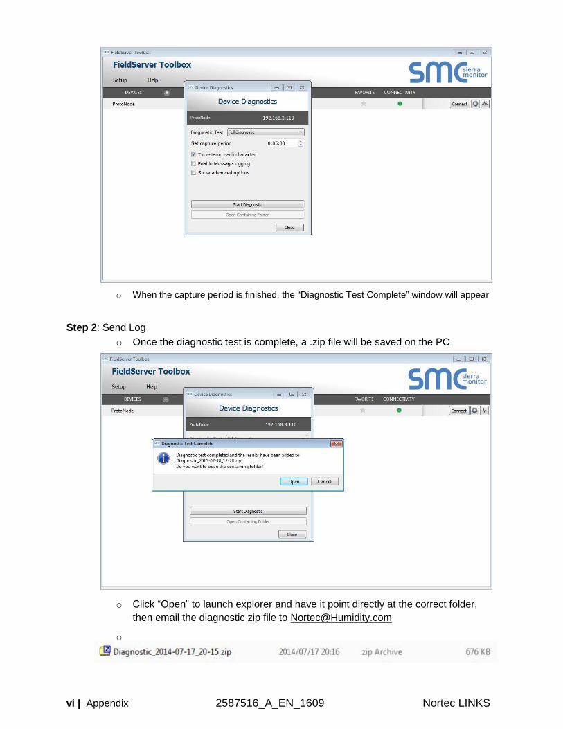
o When the capture period is finished, the “Diagnostic Test Complete” window will appear
Step 2: Send Log
o Once the diagnostic test is complete, a .zip file will be saved on the PC
o Click “Open” to launch explorer and have it point directly at the correct folder,
then email the diagnostic zip file to [email protected]
o
Nortec LINKS 587516_A_EN_1609 Appendix I vii
A.6 Update Firmware
To load a new version of the firmware, follow these instructions:
1. Extract and save the new file onto the local PC.
2. Open a web browser and type the IP Address of the FieldServer in the address bar.
NOTE: Default IP Address is 192.168.168.243
NOTE: Use the FS Toolbox utility if you do not know the IP Address (A.1)
3. Click on the “Diagnostics & Debugging” button.
4. In the Navigation Tree on the left hand side, do the following:
a. Click on “Setup”
b. Click on “File Transfer”
c. Click on the “Firmware” tab
5. In the Firmware tab, click on “Choose Files” and select the firmware file extracted in step 1.
6. Click on the orange “Submit” button.
7. When the download is complete, click on the “System Restart” button.
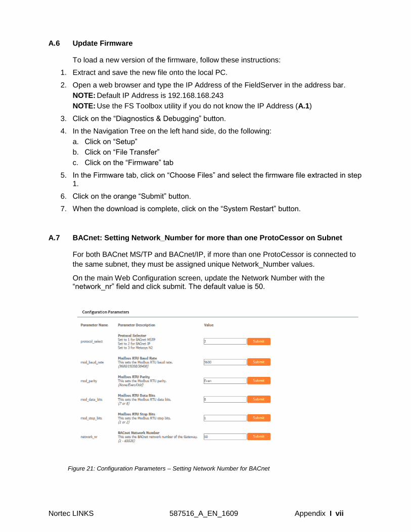
A.7 BACnet: Setting Network_Number for more than one ProtoCessor on Subnet
For both BACnet MS/TP and BACnet/IP, if more than one ProtoCessor is connected to
the same subnet, they must be assigned unique Network_Number values.
On the main Web Configuration screen, update the Network Number with the “network_nr” field and click submit. The default value is 50.
Figure 21: Configuration Parameters – Setting Network Number for BACnet
viii | Appendix 2587516_A_EN_1609 Nortec LINKS
A.8 Securing the ProtoCessor with Passwords
Access to the ProtoCessor can be restricted by enabling a password. There are 2 access levels
defined by 2 account names: Admin and User.
The Admin account has unrestricted access to the ProtoCessor.
The User account can view any ProtoCessor information, but cannot make any changes or
restart the ProtoCessor.
The password needs to be a minimum of eight characters and is case sensitive.
If the password is lost, click cancel on the password authentication popup window, and email the
password recovery token to [email protected] to receive a temporary password from the
support team. Access the ProtoCessor to set a new password.
B VENDOR INFORMATION - NORTEC
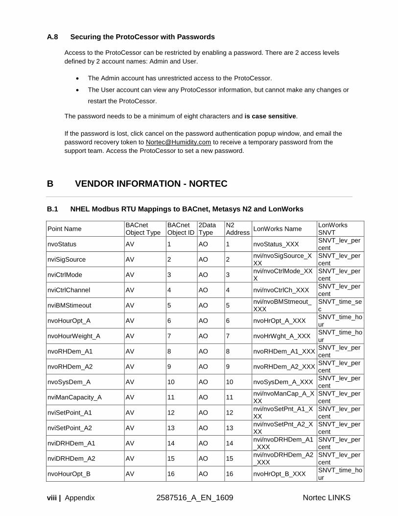
B.1 NHEL Modbus RTU Mappings to BACnet, Metasys N2 and LonWorks
Point Name BACnet Object Type
BACnet Object ID
2Data Type
N2 Address
LonWorks Name LonWorks SNVT
nvoStatus AV 1 AO 1 nvoStatus_XXX SNVT_lev_percent
nviSigSource AV 2 AO 2 nvi/nvoSigSource_XXX
SNVT_lev_percent
nviCtrlMode AV 3 AO 3 nvi/nvoCtrlMode_XXX
SNVT_lev_percent
nviCtrlChannel AV 4 AO 4 nvi/nvoCtrlCh_XXX SNVT_lev_percent
nviBMStimeout AV 5 AO 5 nvi/nvoBMStmeout_XXX
SNVT_time_sec
nvoHourOpt_A AV 6 AO 6 nvoHrOpt_A_XXX SNVT_time_hour
nvoHourWeight_A AV 7 AO 7 nvoHrWght_A_XXX SNVT_time_hour
nvoRHDem_A1 AV 8 AO 8 nvoRHDem_A1_XXX SNVT_lev_percent
nvoRHDem_A2 AV 9 AO 9 nvoRHDem_A2_XXX SNVT_lev_percent
nvoSysDem_A AV 10 AO 10 nvoSysDem_A_XXX SNVT_lev_percent
nviManCapacity_A AV 11 AO 11 nvi/nvoManCap_A_XXX
SNVT_lev_percent
nviSetPoint_A1 AV 12 AO 12 nvi/nvoSetPnt_A1_XXX
SNVT_lev_percent
nviSetPoint_A2 AV 13 AO 13 nvi/nvoSetPnt_A2_XXX
SNVT_lev_percent
nviDRHDem_A1 AV 14 AO 14 nvi/nvoDRHDem_A1_XXX
SNVT_lev_percent
nviDRHDem_A2 AV 15 AO 15 nvi/nvoDRHDem_A2_XXX
SNVT_lev_percent
nvoHourOpt_B AV 16 AO 16 nvoHrOpt_B_XXX SNVT_time_hour
Nortec LINKS 587516_A_EN_1609 Appendix I ix
nvoHourWeight_B AV 17 AO 17 nvoHrWght_B_XXX SNVT_time_hour
nvoRHDem_B1 AV 18 AO 18 nvoRHDem_B1_XXX SNVT_lev_percent
nvoRHDem_B2 AV 19 AO 19 nvoRHDem_B2_XXX SNVT_lev_percent
nvoSysDem_B AV 20 AO 20 nvoSysDem_B_XXX SNVT_lev_percent
nviManCapacity_B AV 21 AO 21 nvi/nvoManCap_B_XXX
SNVT_lev_percent
nviSetPoint_B1 AV 22 AO 22 nvi/nvoSetPnt_B1_XXX
SNVT_lev_percent
nviSetPoint_B2 AV 23 AO 23 nvi/nvoSetPnt_B2_XXX
SNVT_lev_percent
nviDRHDem_B1 AV 24 AO 24 nvi/nvoDRHDem_B1_XXX
SNVT_lev_percent
nviDRHDem_B2 AV 25 AO 25 nvi/nvoDRHDem_B2_XXX
SNVT_lev_percent
nvoConnection BV 1 DO 1 nvoConnectn_XXX SNVT_switch
nvoService BV 2 DO 2 nvoService_XXX SNVT_switch
nvoFault BV 3 DO 3 nvoFault_XXX SNVT_switch
nviDisable BV 4 DO 4 nvi/nvoDisable_XXX SNVT_switch
nvoSecurity_A BV 5 DO 5 nvoSecurty_A_XXX SNVT_switch
nvoBlowerAct_A BV 6 DO 6 nvoBlwrAct_A_XXX SNVT_switch
nvoFanAct_A BV 7 DO 7 nvoFanAct_A_XXX SNVT_switch
nvoSecurity_B BV 8 DO 8 nvoSecurty_B_XXX SNVT_switch
nvoBlowerAct_B BV 9 DO 9 nvoBlwrAct_B_XXX SNVT_switch
nvoFanAct_B BV 10 DO 10 nvoFanAct_B_XXX SNVT_switch
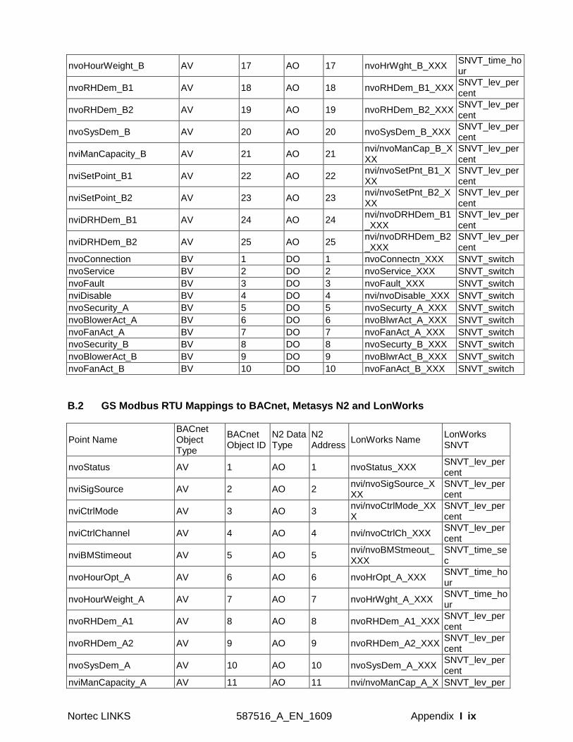
B.2 GS Modbus RTU Mappings to BACnet, Metasys N2 and LonWorks
Point Name BACnet Object Type
BACnet Object ID
N2 Data Type
N2 Address
LonWorks Name LonWorks SNVT
nvoStatus AV 1 AO 1 nvoStatus_XXX SNVT_lev_percent
nviSigSource AV 2 AO 2 nvi/nvoSigSource_XXX
SNVT_lev_percent
nviCtrlMode AV 3 AO 3 nvi/nvoCtrlMode_XXX
SNVT_lev_percent
nviCtrlChannel AV 4 AO 4 nvi/nvoCtrlCh_XXX SNVT_lev_percent
nviBMStimeout AV 5 AO 5 nvi/nvoBMStmeout_XXX
SNVT_time_sec
nvoHourOpt_A AV 6 AO 6 nvoHrOpt_A_XXX SNVT_time_hour
nvoHourWeight_A AV 7 AO 7 nvoHrWght_A_XXX SNVT_time_hour
nvoRHDem_A1 AV 8 AO 8 nvoRHDem_A1_XXX SNVT_lev_percent
nvoRHDem_A2 AV 9 AO 9 nvoRHDem_A2_XXX SNVT_lev_percent
nvoSysDem_A AV 10 AO 10 nvoSysDem_A_XXX SNVT_lev_percent
nviManCapacity_A AV 11 AO 11 nvi/nvoManCap_A_X SNVT_lev_per
x | Appendix 2587516_A_EN_1609 Nortec LINKS
XX cent
nviSetPoint_A1 AV 12 AO 12 nvi/nvoSetPnt_A1_XXX
SNVT_lev_percent
nviSetPoint_A2 AV 13 AO 13 nvi/nvoSetPnt_A2_XXX
SNVT_lev_percent
nviDRHDem_A1 AV 14 AO 14 nvi/nvoDRHDem_A1_XXX
SNVT_lev_percent
nviDRHDem_A2 AV 15 AO 15 nvi/nvoDRHDem_A2_XXX
SNVT_lev_percent
nvoServInterval_A AV 16 AO 16 nvoSrvIntv_A_XXX SNVT_lev_percent
nvoDaysService_A AV 17 AO 17 nvoDaySrvc_A_XXX SNVT_count_f
nvoConnection BV 18 DO 18 nvoConnectn_XXX SNVT_switch
nvoService BV 19 DO 19 nvoSrvc_XXX SNVT_switch
nvoFault BV 20 DO 20 nvoFault_XXX SNVT_switch
nviDisable BV 21 DO 21 nvi/nvoDisable_XXX SNVT_switch
nvoSecurity_A BV 22 DO 22 nvoSecurty_A_XXX SNVT_switch
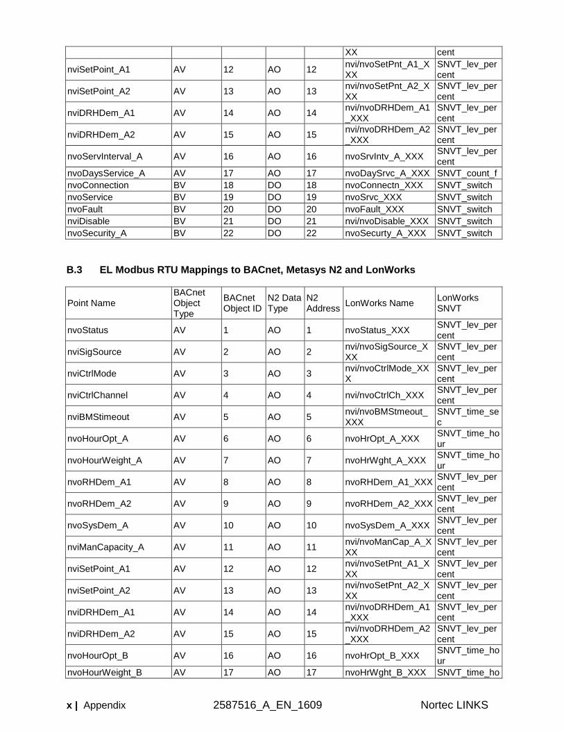
B.3 EL Modbus RTU Mappings to BACnet, Metasys N2 and LonWorks
Point Name BACnet Object Type
BACnet Object ID
N2 Data Type
N2 Address
LonWorks Name LonWorks SNVT
nvoStatus AV 1 AO 1 nvoStatus_XXX SNVT_lev_percent
nviSigSource AV 2 AO 2 nvi/nvoSigSource_XXX
SNVT_lev_percent
nviCtrlMode AV 3 AO 3 nvi/nvoCtrlMode_XXX
SNVT_lev_percent
nviCtrlChannel AV 4 AO 4 nvi/nvoCtrlCh_XXX SNVT_lev_percent
nviBMStimeout AV 5 AO 5 nvi/nvoBMStmeout_XXX
SNVT_time_sec
nvoHourOpt_A AV 6 AO 6 nvoHrOpt_A_XXX SNVT_time_hour
nvoHourWeight_A AV 7 AO 7 nvoHrWght_A_XXX SNVT_time_hour
nvoRHDem_A1 AV 8 AO 8 nvoRHDem_A1_XXX SNVT_lev_percent
nvoRHDem_A2 AV 9 AO 9 nvoRHDem_A2_XXX SNVT_lev_percent
nvoSysDem_A AV 10 AO 10 nvoSysDem_A_XXX SNVT_lev_percent
nviManCapacity_A AV 11 AO 11 nvi/nvoManCap_A_XXX
SNVT_lev_percent
nviSetPoint_A1 AV 12 AO 12 nvi/nvoSetPnt_A1_XXX
SNVT_lev_percent
nviSetPoint_A2 AV 13 AO 13 nvi/nvoSetPnt_A2_XXX
SNVT_lev_percent
nviDRHDem_A1 AV 14 AO 14 nvi/nvoDRHDem_A1_XXX
SNVT_lev_percent
nviDRHDem_A2 AV 15 AO 15 nvi/nvoDRHDem_A2_XXX
SNVT_lev_percent
nvoHourOpt_B AV 16 AO 16 nvoHrOpt_B_XXX SNVT_time_hour
nvoHourWeight_B AV 17 AO 17 nvoHrWght_B_XXX SNVT_time_ho
Nortec LINKS 587516_A_EN_1609 Appendix I xi
ur
nvoRHDem_B1 AV 18 AO 18 nvoRHDem_B1_XXX SNVT_lev_percent
nvoRHDem_B2 AV 19 AO 19 nvoRHDem_B2_XXX SNVT_lev_percent
nvoSysDem_B AV 20 AO 20 nvoSysDem_B_XXX SNVT_lev_percent
nviManCapacity_B AV 21 AO 21 nvi/nvoManCap_B_XXX
SNVT_lev_percent
nviSetPoint_B1 AV 22 AO 22 nvi/nvoSetPnt_B1_XXX
SNVT_lev_percent
nviSetPoint_B2 AV 23 AO 23 nvi/nvoSetPnt_B2_XXX
SNVT_lev_percent
nviDRHDem_B1 AV 24 AO 24 nvi/nvoDRHDem_B1_XXX
SNVT_lev_percent
nviDRHDem_B2 AV 25 AO 25 nvi/nvoDRHDem_B2_XXX
SNVT_lev_percent
nvoConnection BV 1 DO 1 nvoConnectn_XXX SNVT_switch
nvoService BV 2 DO 2 nvoSrvc_XXX SNVT_switch
nvoFault BV 3 DO 3 nvoFault_XXX SNVT_switch
nviDisable BV 4 DO 4 nvi/nvoDisable_XXX SNVT_switch
nvoSecurity_A BV 5 DO 5 nvoSecurty_A_XXX SNVT_switch
nvoBlowerAct_A BV 6 DO 6 nvoBlwrAct_A_XXX SNVT_switch
nvoFanAct_A BV 7 DO 7 nvoFanAct_A_XXX SNVT_switch
nvoSecurity_B BV 8 DO 8 nvoSecurty_B_XXX SNVT_switch
nvoBlowerAct_B BV 9 DO 9 nvoBlwrAct_B_XXX SNVT_switch
nvoFanAct_B BV 10 DO 10 nvoFanAct_B_XXX SNVT_switch
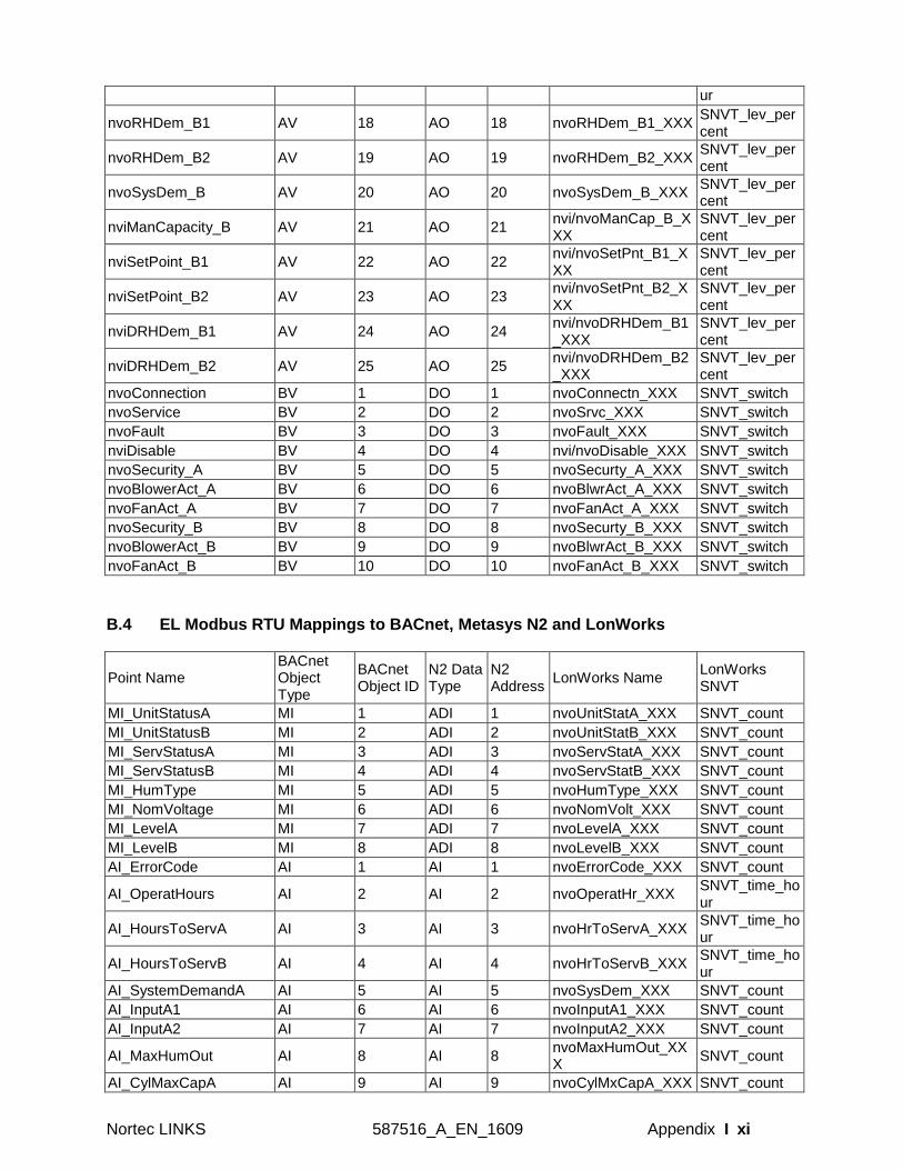
B.4 EL Modbus RTU Mappings to BACnet, Metasys N2 and LonWorks
Point Name BACnet Object Type
BACnet Object ID
N2 Data Type
N2 Address
LonWorks Name LonWorks SNVT
MI_UnitStatusA MI 1 ADI 1 nvoUnitStatA_XXX SNVT_count
MI_UnitStatusB MI 2 ADI 2 nvoUnitStatB_XXX SNVT_count
MI_ServStatusA MI 3 ADI 3 nvoServStatA_XXX SNVT_count
MI_ServStatusB MI 4 ADI 4 nvoServStatB_XXX SNVT_count
MI_HumType MI 5 ADI 5 nvoHumType_XXX SNVT_count
MI_NomVoltage MI 6 ADI 6 nvoNomVolt_XXX SNVT_count
MI_LevelA MI 7 ADI 7 nvoLevelA_XXX SNVT_count
MI_LevelB MI 8 ADI 8 nvoLevelB_XXX SNVT_count
AI_ErrorCode AI 1 AI 1 nvoErrorCode_XXX SNVT_count
AI_OperatHours AI 2 AI 2 nvoOperatHr_XXX SNVT_time_hour
AI_HoursToServA AI 3 AI 3 nvoHrToServA_XXX SNVT_time_hour
AI_HoursToServB AI 4 AI 4 nvoHrToServB_XXX SNVT_time_hour
AI_SystemDemandA AI 5 AI 5 nvoSysDem_XXX SNVT_count
AI_InputA1 AI 6 AI 6 nvoInputA1_XXX SNVT_count
AI_InputA2 AI 7 AI 7 nvoInputA2_XXX SNVT_count
AI_MaxHumOut AI 8 AI 8 nvoMaxHumOut_XXX
SNVT_count
AI_CylMaxCapA AI 9 AI 9 nvoCylMxCapA_XXX SNVT_count
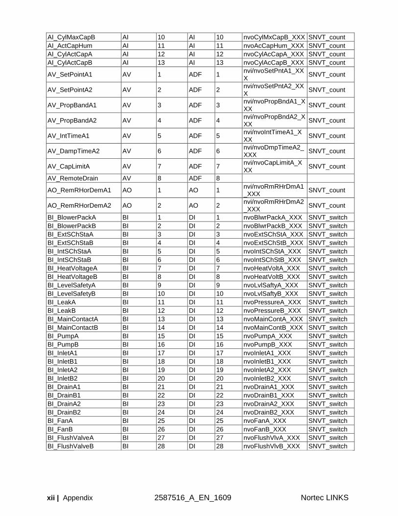
xii | Appendix 2587516_A_EN_1609 Nortec LINKS
AI_CylMaxCapB AI 10 AI 10 nvoCylMxCapB_XXX SNVT_count
AI_ActCapHum AI 11 AI 11 nvoAcCapHum_XXX SNVT_count
AI_CylActCapA AI 12 AI 12 nvoCylAcCapA_XXX SNVT_count
AI_CylActCapB AI 13 AI 13 nvoCylAcCapB_XXX SNVT_count
AV_SetPointA1 AV 1 ADF 1 nvi/nvoSetPntA1_XXX
SNVT_count
AV_SetPointA2 AV 2 ADF 2 nvi/nvoSetPntA2_XXX
SNVT_count
AV_PropBandA1 AV 3 ADF 3 nvi/nvoPropBndA1_XXX
SNVT_count
AV_PropBandA2 AV 4 ADF 4 nvi/nvoPropBndA2_XXX
SNVT_count
AV_IntTimeA1 AV 5 ADF 5 nvi/nvoIntTimeA1_XXX
SNVT_count
AV_DampTimeA2 AV 6 ADF 6 nvi/nvoDmpTimeA2_XXX
SNVT_count
AV_CapLimitA AV 7 ADF 7 nvi/nvoCapLimitA_XXX
SNVT_count
AV_RemoteDrain AV 8 ADF 8
AO_RemRHorDemA1 AO 1 AO 1 nvi/nvoRmRHrDmA1_XXX
SNVT_count
AO_RemRHorDemA2 AO 2 AO 2 nvi/nvoRmRHrDmA2_XXX
SNVT_count
BI_BlowerPackA BI 1 DI 1 nvoBlwrPackA_XXX SNVT_switch
BI_BlowerPackB BI 2 DI 2 nvoBlwrPackB_XXX SNVT_switch
BI_ExtSChStaA BI 3 DI 3 nvoExtSChStA_XXX SNVT_switch
BI_ExtSChStaB BI 4 DI 4 nvoExtSChStB_XXX SNVT_switch
BI_IntSChStaA BI 5 DI 5 nvoIntSChStA_XXX SNVT_switch
BI_IntSChStaB BI 6 DI 6 nvoIntSChStB_XXX SNVT_switch
BI_HeatVoltageA BI 7 DI 7 nvoHeatVoltA_XXX SNVT_switch
BI_HeatVoltageB BI 8 DI 8 nvoHeatVoltB_XXX SNVT_switch
BI_LevelSafetyA BI 9 DI 9 nvoLvlSaftyA_XXX SNVT_switch
BI_LevelSafetyB BI 10 DI 10 nvoLvlSaftyB_XXX SNVT_switch
BI_LeakA BI 11 DI 11 nvoPressureA_XXX SNVT_switch
BI_LeakB BI 12 DI 12 nvoPressureB_XXX SNVT_switch
BI_MainContactA BI 13 DI 13 nvoMainContA_XXX SNVT_switch
BI_MainContactB BI 14 DI 14 nvoMainContB_XXX SNVT_switch
BI_PumpA BI 15 DI 15 nvoPumpA_XXX SNVT_switch
BI_PumpB BI 16 DI 16 nvoPumpB_XXX SNVT_switch
BI_InletA1 BI 17 DI 17 nvoInletA1_XXX SNVT_switch
BI_InletB1 BI 18 DI 18 nvoInletB1_XXX SNVT_switch
BI_InletA2 BI 19 DI 19 nvoInletA2_XXX SNVT_switch
BI_InletB2 BI 20 DI 20 nvoInletB2_XXX SNVT_switch
BI_DrainA1 BI 21 DI 21 nvoDrainA1_XXX SNVT_switch
BI_DrainB1 BI 22 DI 22 nvoDrainB1_XXX SNVT_switch
BI_DrainA2 BI 23 DI 23 nvoDrainA2_XXX SNVT_switch
BI_DrainB2 BI 24 DI 24 nvoDrainB2_XXX SNVT_switch
BI_FanA BI 25 DI 25 nvoFanA_XXX SNVT_switch
BI_FanB BI 26 DI 26 nvoFanB_XXX SNVT_switch
BI_FlushValveA BI 27 DI 27 nvoFlushVlvA_XXX SNVT_switch
BI_FlushValveB BI 28 DI 28 nvoFlushVlvB_XXX SNVT_switch
Nortec LINKS 587516_A_EN Appendix I xiii
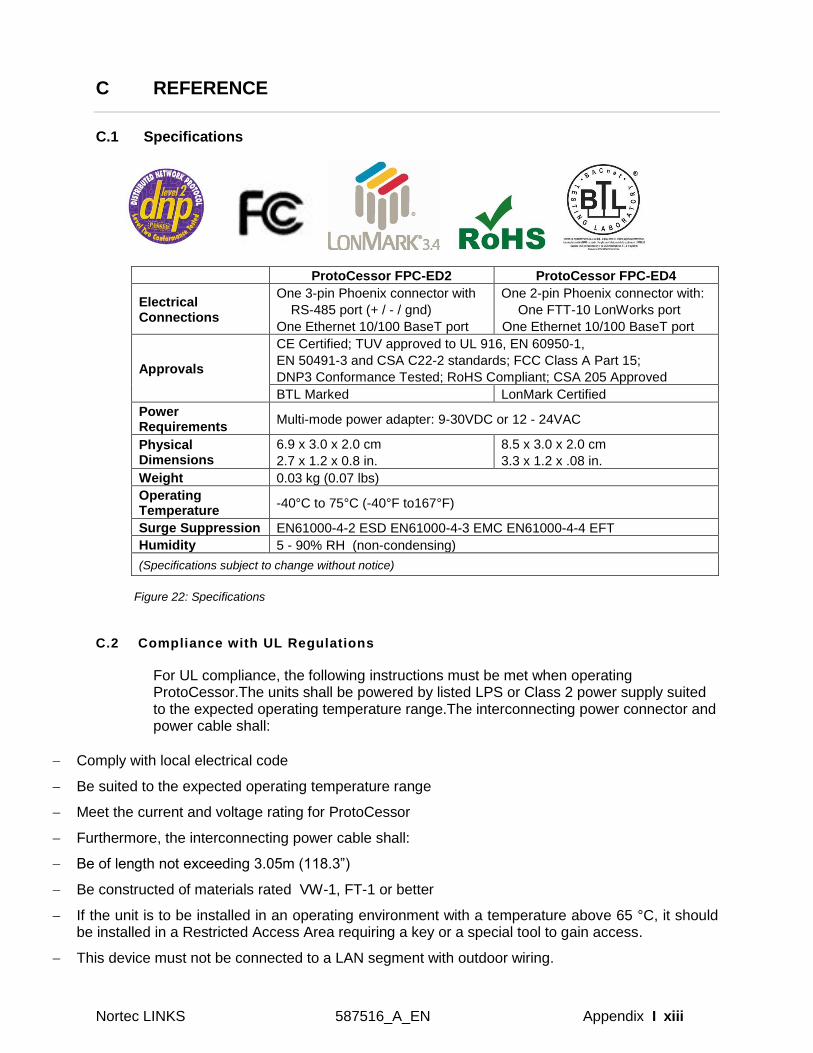
C REFERENCE
C.1 Specifications
ProtoCessor FPC-ED2 ProtoCessor FPC-ED4
Electrical Connections
One 3-pin Phoenix connector with
RS-485 port (+ / - / gnd)
One Ethernet 10/100 BaseT port
One 2-pin Phoenix connector with:
One FTT-10 LonWorks port
One Ethernet 10/100 BaseT port
Approvals
CE Certified; TUV approved to UL 916, EN 60950-1,
EN 50491-3 and CSA C22-2 standards; FCC Class A Part 15;
DNP3 Conformance Tested; RoHS Compliant; CSA 205 Approved
BTL Marked LonMark Certified
Power Requirements
Multi-mode power adapter: 9-30VDC or 12 - 24VAC
Physical Dimensions
6.9 x 3.0 x 2.0 cm
2.7 x 1.2 x 0.8 in.
8.5 x 3.0 x 2.0 cm
3.3 x 1.2 x .08 in.
Weight 0.03 kg (0.07 lbs)
Operating Temperature
-40°C to 75°C (-40°F to167°F)
Surge Suppression EN61000-4-2 ESD EN61000-4-3 EMC EN61000-4-4 EFT
Humidity 5 - 90% RH (non-condensing)
(Specifications subject to change without notice)
Figure 22: Specifications
C.2 Compliance with UL Regulations
For UL compliance, the following instructions must be met when operating ProtoCessor.The units shall be powered by listed LPS or Class 2 power supply suited to the expected operating temperature range.The interconnecting power connector and power cable shall:
Comply with local electrical code
Be suited to the expected operating temperature range
Meet the current and voltage rating for ProtoCessor
Furthermore, the interconnecting power cable shall:
Be of length not exceeding 3.05m (118.3”)
Be constructed of materials rated VW-1, FT-1 or better
If the unit is to be installed in an operating environment with a temperature above 65 °C, it should be installed in a Restricted Access Area requiring a key or a special tool to gain access.
This device must not be connected to a LAN segment with outdoor wiring.

xiv | Appendix 2587516_A_EN_1609 Nortec LINKS
Page intentionally left blank
Warranty
Nortec Humidity Inc. and/or Nortec Humidity Ltd. (hereinafter collectively referred to as THE COMPANY), warrant for a period of two years after installation or 30 months from manufacturer’s ship date, whichever date is earlier, that THE COMPANY’s manufactured and assembled products, not otherwise expressly warranted, are free from defects in material and workmanship. No warranty is made against corrosion, deterioration, or suitability of substituted materials used as a result of compliance with government regulations.
THE COMPANY’s obligations and liabilities under this warranty are limited to furnishing replacement parts to the customer, F.O.B. THE COMPANY’s factory, provided that the defective part(s) is returned freight prepaid by the customer. The replacement parts are warranted for the balance of the term of the warranty on the original humidifier or 90 days, whichever is longer.
The warranties set forth herein are in lieu of all other warranties expressed or implied by law. No liability whatsoever shall be attached to THE COMPANY until said products have been paid for in full and then said liability shall be limited to the original purchase price for the product. Any further warranty must be in writing, signed by an officer of THE COMPANY.
THE COMPANY’s limited warranty on accessories, not manufactured by the COMPANY, such as controls, humidistats, pumps, etc., is limited to the warranty of the original equipment manufacturer from date of original shipment of humidifier.
THE COMPANY makes no warranty and assumes no liability unless the equipment is installed in strict accordance with a copy of the catalog and installation manual in effect at the date of purchase, and by a contractor approved by THE COMPANY to install such equipment.
THE COMPANY makes no warranty and assumes no liability whatsoever for consequential damage or damage resulting directly from misapplication, incorrect sizing or lack of proper maintenance of the equipment.
THE COMPANY makes no warranty and assumes no liability whatsoever for damage to the humidifier, supply lines, drain lines, or steam distribution systems caused by freezing.
THE COMPANY reserves the right to change the design, specifications and performance
criteria of its products without notice or obligation.

Consulting, Sales and Service:
U.S.A. 835 Commerce Park Ave Ogdensburg, NY 1366-2209
CANADA 2740 Fenton Road Ottawa, ON, K1T 3T7
Tel: 1.866.NORTEC1 Fax: 613.822.7964
Email: [email protected] Website: www.humidity.com