INSTALLATION AND OPERATION MANUAL KBN2 DIGITAL AC ADJUSTABLE SPEED DRIVES · 2016-07-18 ·...
80
FREQ.SET 0 100 STOP REV FWD FUN RUN SEQ Hz/RPM FRQ ENTER READ NDOP-01 FUN RESET DSP AMP REV FWD VOLT POWER CONV.EQ LISTED 16KJ. E177007 ISO 9002 Automation and Control INSTALLATION AND OPERATION MANUAL KBN2 DIGITAL AC ADJUSTABLE SPEED DRIVES for Use with 1/2 - 30 HP Inverter Duty, TEFC and TENV 3-Phase Induction Motors © 2003 KB Electronics, Inc. (See back cover) This Manual Covers Models: KBN2-2250-1, 2201-1, 2202-1, 2203-1, 2305-1, 2307-1, 2310-1, 2315-1, 2320-1, 2330-1, 4301-1, 4302-1, 4303-1, 4305-1, 4307-1, 4310-1, 4315-1, 4320-1, 4330-1 The information contained in this manual is intended to be accurate. However, the manufacturer retains the right to make changes in design which may not be included herein. ! See Safety Warning on page 6 208/230 or 380 - 460 Volts, 50/60 Hz, 1 & 3 Phase AC Line Input Note: This drive has been programmed to operate 60 Hz motors. For 50 Hz motor operation, see Section VIII-C-2, on page 32. * See Note 1, on page 10.
Transcript of INSTALLATION AND OPERATION MANUAL KBN2 DIGITAL AC ADJUSTABLE SPEED DRIVES · 2016-07-18 ·...
FREQ.SET0 100
STOP
REVFWD
FUN
RUN
SEQ
Hz/RPM
FRQ
ENTERREAD
NDOP-01
FUN
RESET
DSP
AMP
REVFWD
VOLT
POWER CONV.EQLISTED 16KJ.
E177007
ISO9002
Automation and Control
INSTALLATION AND OPERATION MANUAL
KBN2 DIGITAL ACADJUSTABLE SPEED DRIVES
for Use with 1/2 - 30 HP Inverter Duty, TEFC and TENV 3-Phase Induction Motors
© 2003 KB Electronics, Inc.(See back cover)
This Manual Covers Models:
KBN2-2250-1, 2201-1, 2202-1, 2203-1, 2305-1, 2307-1, 2310-1, 2315-1, 2320-1, 2330-1,
4301-1, 4302-1, 4303-1, 4305-1, 4307-1, 4310-1, 4315-1, 4320-1, 4330-1
The information contained in this manual is intended to be accurate. However, the
manufacturer retains the right to make changes in design which may not be included herein.
! See Safety Warning on page 6
208/230 or 380 - 460 Volts, 50/60 Hz, 1 & 3 Phase AC Line Input
Note: This drive hasbeen programmedto operate 60 Hzmotors. For 50 Hzmotor operation,see Section VIII-C-2,on page 32.
* See Note 1, on page 10.

TABLE OF CONTENTSSection Pagei. Simplified Instructions . . . . . . . . . . . . . . . . . . . . . . . . . . . . . . . . . . . . . . . . . . . . . . . . . . . . . . . . . . . . . 5
ii. Safety Warning . . . . . . . . . . . . . . . . . . . . . . . . . . . . . . . . . . . . . . . . . . . . . . . . . . . . . . . . . . . . . . . . . . 6
I. Introduction . . . . . . . . . . . . . . . . . . . . . . . . . . . . . . . . . . . . . . . . . . . . . . . . . . . . . . . . . . . . . . . . . . . . . 6
II. Mounting Instructions . . . . . . . . . . . . . . . . . . . . . . . . . . . . . . . . . . . . . . . . . . . . . . . . . . . . . . . . . . . . 15
III. Reconditioning the Bus Capacitors . . . . . . . . . . . . . . . . . . . . . . . . . . . . . . . . . . . . . . . . . . . . . . . . . . 15
IV. Terminal Block TM1 Wiring Instructions (Power Connections) . . . . . . . . . . . . . . . . . . . . . . . . . . . . . . 15
V. Terminal Block TM2 Wiring Instructions (Signal Connections) . . . . . . . . . . . . . . . . . . . . . . . . . . . . . . 17
A. External Run/Stop-Forward/Reverse Connection . . . . . . . . . . . . . . . . . . . . . . . . . . . . . . . . . . . . . 18
B. External Frequency Control . . . . . . . . . . . . . . . . . . . . . . . . . . . . . . . . . . . . . . . . . . . . . . . . . . . . . 19
C. Multifunction Output Relay Connection . . . . . . . . . . . . . . . . . . . . . . . . . . . . . . . . . . . . . . . . . . . . 24
D. Multifunction Analog Output Connection . . . . . . . . . . . . . . . . . . . . . . . . . . . . . . . . . . . . . . . . . . . 24
E. Multifunction Open Collector Output Connection . . . . . . . . . . . . . . . . . . . . . . . . . . . . . . . . . . . . . 24
F. Reset Connection . . . . . . . . . . . . . . . . . . . . . . . . . . . . . . . . . . . . . . . . . . . . . . . . . . . . . . . . . . . . 25
G. RS-232 or RS-485 Communication Cable Connection . . . . . . . . . . . . . . . . . . . . . . . . . . . . . . . . . 25
VI. AC Line Fusing . . . . . . . . . . . . . . . . . . . . . . . . . . . . . . . . . . . . . . . . . . . . . . . . . . . . . . . . . . . . . . . . . 25
VII. Recommended High Voltage Dielectric Withstand Testing (Hi-Pot) . . . . . . . . . . . . . . . . . . . . . . . . . . 25
VIII. Drive Operation . . . . . . . . . . . . . . . . . . . . . . . . . . . . . . . . . . . . . . . . . . . . . . . . . . . . . . . . . . . . . . . . . 27
A. Digital Keypad Description . . . . . . . . . . . . . . . . . . . . . . . . . . . . . . . . . . . . . . . . . . . . . . . . . . . . . . 27
B. Digital Keypad Operation . . . . . . . . . . . . . . . . . . . . . . . . . . . . . . . . . . . . . . . . . . . . . . . . . . . . . . . 29
1. Setting Drive Output Frequency Using the Keypad . . . . . . . . . . . . . . . . . . . . . . . . . . . . . . . . . 29
2. Programming the Drive . . . . . . . . . . . . . . . . . . . . . . . . . . . . . . . . . . . . . . . . . . . . . . . . . . . . . . 29
C. Important Programming Functions . . . . . . . . . . . . . . . . . . . . . . . . . . . . . . . . . . . . . . . . . . . . . . . . 31
1. Motor Current Rating [F070] . . . . . . . . . . . . . . . . . . . . . . . . . . . . . . . . . . . . . . . . . . . . . . . . . . 31
2. 60 Hz, 50 Hz Motor Operation (Volts/Hz Pattern) [F005] . . . . . . . . . . . . . . . . . . . . . . . . . . . . . 32
3. AC line Input Voltage [F030] . . . . . . . . . . . . . . . . . . . . . . . . . . . . . . . . . . . . . . . . . . . . . . . . . . 32
D. Other Useful Programming . . . . . . . . . . . . . . . . . . . . . . . . . . . . . . . . . . . . . . . . . . . . . . . . . . . . . . 33
1. External Run/Stop-Forward/Reverse Control [F010] . . . . . . . . . . . . . . . . . . . . . . . . . . . . . . . . 33
2. External Forward-Stop-Reverse Control [F003] . . . . . . . . . . . . . . . . . . . . . . . . . . . . . . . . . . . . 33
3. Frequency Control Method [F011] . . . . . . . . . . . . . . . . . . . . . . . . . . . . . . . . . . . . . . . . . . . . . . 34
4. Analog Signal Input Scaling [F026, F027, F028, F029] . . . . . . . . . . . . . . . . . . . . . . . . . . . . . . 35
5. Manual and Automatic Restart [F010, F016, F032, F035] . . . . . . . . . . . . . . . . . . . . . . . . . . . . 37
6. Load Regulation and Torque Boost [F047, F072, F005, F075, F076, F070] . . . . . . . . . . . . . . 39
7. Display Modes [F047, F051, F052] . . . . . . . . . . . . . . . . . . . . . . . . . . . . . . . . . . . . . . . . . . . . . 43
E. Programmable Functions (Summary) . . . . . . . . . . . . . . . . . . . . . . . . . . . . . . . . . . . . . . . . . . . . . . 46
IX. Programmable Functions (Detailed) . . . . . . . . . . . . . . . . . . . . . . . . . . . . . . . . . . . . . . . . . . . . . . . . . . 53
X. Optional Accessories . . . . . . . . . . . . . . . . . . . . . . . . . . . . . . . . . . . . . . . . . . . . . . . . . . . . . . . . . . . . . 76
XI. Limited Warranty . . . . . . . . . . . . . . . . . . . . . . . . . . . . . . . . . . . . . . . . . . . . . . . . . . . . . . . . . . . . . . . . 80
Tables Page1. Model Number Identification . . . . . . . . . . . . . . . . . . . . . . . . . . . . . . . . . . . . . . . . . . . . . . . . . . . . . . . . 9
2. General Performance Specifications . . . . . . . . . . . . . . . . . . . . . . . . . . . . . . . . . . . . . . . . . . . . . . . . . . 9
3. Electrical Ratings . . . . . . . . . . . . . . . . . . . . . . . . . . . . . . . . . . . . . . . . . . . . . . . . . . . . . . . . . . . . . . . . 10
4. Terminal Block TM1 Wiring Information . . . . . . . . . . . . . . . . . . . . . . . . . . . . . . . . . . . . . . . . . . . . . . . 16
5. Terminal Block TM2 Wiring Information (All Models) . . . . . . . . . . . . . . . . . . . . . . . . . . . . . . . . . . . . . . 18
6. External Run/Stop-Forward/Reverse Control [F003] . . . . . . . . . . . . . . . . . . . . . . . . . . . . . . . . . . . . . 19
ii

TABLE OF CONTENTS (Continued)Tables (Continued) Page7. Signal Input, F011, and Jumper JP1/JP2 Setting . . . . . . . . . . . . . . . . . . . . . . . . . . . . . . . . . . . . . . . 19
8. Settings for External Up/Down Frequency Control . . . . . . . . . . . . . . . . . . . . . . . . . . . . . . . . . . . . . . . 22
9. Selecting Preset Speed Using Multifunction Input Terminals 6, 7, 8 . . . . . . . . . . . . . . . . . . . . . . . . . . 23
10. Recommended Fuse, Circuit Breaker, or Magnetic Contactor Rating . . . . . . . . . . . . . . . . . . . . . . . . 25
11. LED Status Indicators . . . . . . . . . . . . . . . . . . . . . . . . . . . . . . . . . . . . . . . . . . . . . . . . . . . . . . . . . . . . 29
12. Signal Input and Jumper JP1/JP2 Setting . . . . . . . . . . . . . . . . . . . . . . . . . . . . . . . . . . . . . . . . . . . . . 35
13A. Manual Restart for “All Faults” Including AC Power Loss - Keypad Operation . . . . . . . . . . . . . . . . . . 37
13B. Manual Restart for “All Faults” Including AC Power Loss - External Run/Stop Contacts . . . . . . . . . . 37
14A. Automatic Restart for “All Faults” Except AC Power Loss - Keypad Operation . . . . . . . . . . . . . . . . . 38
14B. Automatic Restart for “All Faults” Except AC Power Loss - External Run/Stop Contacts . . . . . . . . . . 38
15. Automatic Restart for “All Faults” Including AC Power Loss - External Contacts . . . . . . . . . . . . . . . . 39
16. Functions F070, F071, F075, F076, F005 Set for Widely Changing Loads . . . . . . . . . . . . . . . . . . . . 43
17. Programmable Functions Summary List . . . . . . . . . . . . . . . . . . . . . . . . . . . . . . . . . . . . . . . . . . . 46 - 52
18. Drive Model and Horsepower Code Setting . . . . . . . . . . . . . . . . . . . . . . . . . . . . . . . . . . . . . . . . . . . 53
19. Preset Speeds # 1 - 7 . . . . . . . . . . . . . . . . . . . . . . . . . . . . . . . . . . . . . . . . . . . . . . . . . . . . . . . . . . . . 58
20. Drive Model and Factory Setting of Motor Rated Current . . . . . . . . . . . . . . . . . . . . . . . . . . . . . . . . . 68
21. Drive Model and Factory Setting of Motor No Load Current . . . . . . . . . . . . . . . . . . . . . . . . . . . . . . . 70
22. Fault Codes and Corrective Actions . . . . . . . . . . . . . . . . . . . . . . . . . . . . . . . . . . . . . . . . . . . . . . 74 - 76
23. Display Status when the Drive Is In External Start/Stop Mode . . . . . . . . . . . . . . . . . . . . . . . . . . . . . . 76
24. RFI Filters . . . . . . . . . . . . . . . . . . . . . . . . . . . . . . . . . . . . . . . . . . . . . . . . . . . . . . . . . . . . . . . . . . . . . 78
25. Brake Resistors . . . . . . . . . . . . . . . . . . . . . . . . . . . . . . . . . . . . . . . . . . . . . . . . . . . . . . . . . . . . . . . . . 78
26. Extension Cables . . . . . . . . . . . . . . . . . . . . . . . . . . . . . . . . . . . . . . . . . . . . . . . . . . . . . . . . . . . . . . . . 79
Figures Page1A. Mechanical Specifications for Models
KBN2-2250-1, 2201-1 (Pkg. D) . . . . . . . . . . . . . . . . . . . . . . . . . . . . . . . . . . . . . . . . . . . . . . . . . . . . . 11
1B. Mechanical Specifications for Models
KBN2-2202-1, 4301-1, 4302-1 (Pkg. E) . . . . . . . . . . . . . . . . . . . . . . . . . . . . . . . . . . . . . . . . . . . . . . 11
1C. Mechanical Specifications for Models
KBN2-2203-1, 2305-1, 4303-1, 4305-1 (Pkg. F) . . . . . . . . . . . . . . . . . . . . . . . . . . . . . . . . . . . . . . . 12
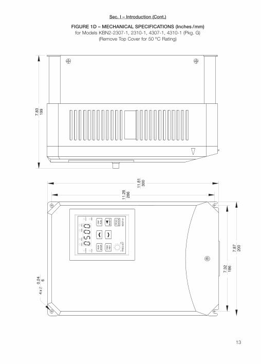
1D. Mechanical Specifications for Models
KBN2-2307-1, 2310-1, 4307-1, 4310-1 (Pkg. G) . . . . . . . . . . . . . . . . . . . . . . . . . . . . . . . . . . . . . . . 13
1E. Mechanical Specifications for Models
KBN2-2315-1, 2320-1, 2330-1, 4315-1, 4320-1, 4330-1 (Pkg. H) . . . . . . . . . . . . . . . . . . . . . . . . . . 14
2A. Pkg. D, E, F, G Terminal Block TM1 Designation . . . . . . . . . . . . . . . . . . . . . . . . . . . . . . . . . . . . . . . . 15
2B. Pkg. H Terminal Block TM1 Designation . . . . . . . . . . . . . . . . . . . . . . . . . . . . . . . . . . . . . . . . . . . . . . 15
3A. Pkg. D, E, F, Power Connections with 1φ AC Line Input . . . . . . . . . . . . . . . . . . . . . . . . . . . . . . . . . . 16
3B. Pkg. D, E, F, G Power Connections with 3 φ AC Line Input . . . . . . . . . . . . . . . . . . . . . . . . . . . . . . . . 16
3C. Pkg. H Power Connections . . . . . . . . . . . . . . . . . . . . . . . . . . . . . . . . . . . . . . . . . . . . . . . . . . . . . . . . 17
4. Terminal Block TM2 Designation and General Connection Diagram (All Models) . . . . . . . . . . . . . . . . 17
5A. Forward/Stop-Reverse/Stop Connection . . . . . . . . . . . . . . . . . . . . . . . . . . . . . . . . . . . . . . . . . . . . . . 18
5B. Run/Stop-Forward/Reverse Connection . . . . . . . . . . . . . . . . . . . . . . . . . . . . . . . . . . . . . . . . . . . . . . 18
5C. 3-Wire Start/Stop Connection . . . . . . . . . . . . . . . . . . . . . . . . . . . . . . . . . . . . . . . . . . . . . . . . . . . . . . 18
5D. 3-Wire Start/Stop Connection with Reverse . . . . . . . . . . . . . . . . . . . . . . . . . . . . . . . . . . . . . . . . . . . 18
iii

TABLE OF CONTENTS (Continued)Figures (Continued) Page6. Typical Location of Jumper JP1/JP2 . . . . . . . . . . . . . . . . . . . . . . . . . . . . . . . . . . . . . . . . . . . . . . . . . 20
7A. Remote Speed Potentiometer Connection . . . . . . . . . . . . . . . . . . . . . . . . . . . . . . . . . . . . . . . . . . . . 20
7B. Jumper JP1 Set for Remote Speed Potentiometer . . . . . . . . . . . . . . . . . . . . . . . . . . . . . . . . . . . . . . 20
8A. Voltage Following Connection . . . . . . . . . . . . . . . . . . . . . . . . . . . . . . . . . . . . . . . . . . . . . . . . . . . . . . 20
8B. Jumper JP2 Set for 0 - 10 VDC Voltage Following Signal Input . . . . . . . . . . . . . . . . . . . . . . . . . . . . . 20
8C. Voltage Following Connection with Series Resistor . . . . . . . . . . . . . . . . . . . . . . . . . . . . . . . . . . . . . . 20
9A. Current Following Connection . . . . . . . . . . . . . . . . . . . . . . . . . . . . . . . . . . . . . . . . . . . . . . . . . . . . . . 21
9B. Jumper JP1 Set for Current Following Signal Input . . . . . . . . . . . . . . . . . . . . . . . . . . . . . . . . . . . . . . 21
10A. Multifunction Input Terminals Connection with Normally Open Contacts . . . . . . . . . . . . . . . . . . . . . . 21
10B. Multifunction Input Terminals Connection with Normally Closed Contacts . . . . . . . . . . . . . . . . . . . . . 21
10C. Multifunction Input Terminals Connection with Open Collector . . . . . . . . . . . . . . . . . . . . . . . . . . . . . . 22
11A. Up/Down Frequency Control Connection with Normally Open Contacts . . . . . . . . . . . . . . . . . . . . . . 22
11B. Up/Down Frequency Control Connection with Normally Closed Contacts . . . . . . . . . . . . . . . . . . . . . 22
11C. Up/Down Frequency Control Connection with Open Collector . . . . . . . . . . . . . . . . . . . . . . . . . . . . . 22
12. Multifunction Output Relay Connection . . . . . . . . . . . . . . . . . . . . . . . . . . . . . . . . . . . . . . . . . . . . . . . 24
13. Multifunction Analog Output Connection . . . . . . . . . . . . . . . . . . . . . . . . . . . . . . . . . . . . . . . . . . . . . . 24
14. Multifunction Open Collector Output Connection . . . . . . . . . . . . . . . . . . . . . . . . . . . . . . . . . . . . . . . . 24
15A. Reset Connection . . . . . . . . . . . . . . . . . . . . . . . . . . . . . . . . . . . . . . . . . . . . . . . . . . . . . . . . . . . . . . . 25
15B. Reset Connection with Open Collector . . . . . . . . . . . . . . . . . . . . . . . . . . . . . . . . . . . . . . . . . . . . . . . 25
16. Hi-Pot Setup . . . . . . . . . . . . . . . . . . . . . . . . . . . . . . . . . . . . . . . . . . . . . . . . . . . . . . . . . . . . . . . . . . . 26
17. Digital Keypad Layout . . . . . . . . . . . . . . . . . . . . . . . . . . . . . . . . . . . . . . . . . . . . . . . . . . . . . . . . . . . . 27
18. Flow Chart to Change Set Frequency – Drive in STOP Mode . . . . . . . . . . . . . . . . . . . . . . . . . . . . . . 30
19. Flow Chart to Program F001 [Acceleration Time # 1] . . . . . . . . . . . . . . . . . . . . . . . . . . . . . . . . . . . . 30
20. Input Signal Scaling . . . . . . . . . . . . . . . . . . . . . . . . . . . . . . . . . . . . . . . . . . . . . . . . . . . . . . . . . . . . . . 35
21A. Low-to-High Analog Input Signal Slope (Positive) . . . . . . . . . . . . . . . . . . . . . . . . . . . . . . . . . . . . . . . 36
21B. High-to-Low Analog Input Signal Slope (Negative) . . . . . . . . . . . . . . . . . . . . . . . . . . . . . . . . . . . . . . . 36
22. Custom Volts/Hz Pattern for a 400 Hz - 230 Volt AC Motor . . . . . . . . . . . . . . . . . . . . . . . . . . . . . . . 44
23. Flow Chart for Basic Display . . . . . . . . . . . . . . . . . . . . . . . . . . . . . . . . . . . . . . . . . . . . . . . . . . . . . . . 44
24. Flow Chart Showing Motor Voltage, Bus Voltage, and
Motor Current Added to the Basic Display . . . . . . . . . . . . . . . . . . . . . . . . . . . . . . . . . . . . . . . . . . . . 44
25. Flow Chart Showing the Basic Display Changed from
Drive Output Frequency to Motor RPM . . . . . . . . . . . . . . . . . . . . . . . . . . . . . . . . . . . . . . . . . . . . . . . 45
26. Flow Chart Showing the Basic Display Changed from
Drive Output Frequency to Line Speed Display (Custom Units) . . . . . . . . . . . . . . . . . . . . . . . . . . . . . 45
27. Volts/Hz Pattern . . . . . . . . . . . . . . . . . . . . . . . . . . . . . . . . . . . . . . . . . . . . . . . . . . . . . . . . . . . . . . . . 55
28. Controlled Deceleration-to-Stop with DC Injection Braking (Rapid Stop) . . . . . . . . . . . . . . . . . . . . . . 62
29. Analog Output Voltage Gain . . . . . . . . . . . . . . . . . . . . . . . . . . . . . . . . . . . . . . . . . . . . . . . . . . . . . . . 62
30. Volts/Hz Curve Modification (Torque Boost) . . . . . . . . . . . . . . . . . . . . . . . . . . . . . . . . . . . . . . . . . . . . 69
31. Recommended RFI Filter Connection . . . . . . . . . . . . . . . . . . . . . . . . . . . . . . . . . . . . . . . . . . . . . . . . 77
iv

i. SIMPLIFIED INSTRUCTIONS
5
It is recommended that this drive be used with Inverter Duty or TENV motors which pro-vide full rated torque over an extended speed range without overheating. If external fancooling is provided, open-ventilated motors can also achieve an extended speed rangeat full rated torque. A box fan or blower with a minimum of 100 CFM per HP is recom-mended. Mount the fan such that the motor is surrounded by the airflow.
Application Information – Some motors have low speed characteristics which cause over-heating and winding failure under light or no load conditions. If the motor is operated in thismanner for an extended period of time, it is recommended that the unloaded motor currentbe checked from 2 - 15 Hz (60 - 450 RPM) to ensure that the motor current does not exceedthe nameplate rating. Do not use motor if the motor current exceeds the nameplate rating.
Note: This drive has been programmed to operate 60 Hz motors. For 50 Hz motors, seeSection VIII-C-2, on page 32.
WARNING! Disconnect the main power when making connections to the drive.
Note: It is recommended that the bus capacitors be reconditioned if this product has been instorage for over one year. To recondition the capacitors, apply the AC line, with the control inthe Stop Mode, for a minimum of one hour.
A. AC Line Connection – Connect the AC line to Terminals L1, L2 (for single phase AC lineinput) or L1, L2, L3 (for 3-phase AC line input), of Terminal Block TM1, as described inSection IV-A, on page 16. Be sure the AC line input voltage matches the drive rated inputvoltage. See Section VIII-C-3, on page 32.
B. Ground Connection – Connect the ground wire (earth) to the ground screw as shown inFigures 3A, 3B, and 3C, on pages 16 and 17.
C. AC Line Fusing – Install a fuse or circuit breaker in the AC line (a magnetic contactor isrecommended for models with 3-phase AC line input). Fuse each conductor that is not atground potential. See Section VI, on page 25, for recommended ratings.
D. Motor Connection – Connect the motor to Terminals T1 (U), T2 (V), T3 (W) of TerminalBlock TM1, as shown in Figures 3A, 3B, and 3C, on pages 16 and 17, and as describedin Section IV-C, on page 17. Motor cable length should not exceed 100 feet (30 m) - spe-cial reactors may be required - contact the Sales Department.
E. Power Up and Basic Keypad Operation – When applying power to the drive, the DriveAC Line Input Voltage Setting [F030] will flash four times on the display and the VOLT LEDwill flash. The set frequency (factory setting is “05.00”) will then flash on the display, theVOLT LED will turn off, and the Hz/RPM LED will flash. To increase the motor speed, pressthe key until the desired frequency is displayed. To decrease the motor speed, press thekey until the desired frequency is displayed. Press the RUN/STOP key to start the drive.
!
IMPORTANT – You must read these simplified operating instructions before pro-ceeding. These instructions are to be used as a reference only and are not intendedto replace the detailed instructions provided herein. You must read the SafetyWarning, on page 6, before proceeding.
Sec. i – Simplified Inst.
I. INTRODUCTIONThank you for purchasing the GENESIS™ KBN2 Series Inverter. KB Electronics, Inc. is com-mitted to providing total customer satisfaction by providing quality products that are easy toinstall and operate.
The KBN2 series of industrial inverters are designed for 3-phase induction motors thru30 HP. Housed in NEMA-1 enclosures, they are available with 208/230 and 380/460 VoltsAC - 50/60 Hz AC line input. The drives contain a remote mountable digital keypad with a4-digit LED display and “status” indicators. In addition to output frequency, the display canbe programmed to indicate a variety of functions including motor voltage and current, RPM,and custom units (Line Speed).
An isolated multifunction terminal block provides for external control of all drive operations.The start/stop circuitry can be wired in several ways, including 2-wire and 3-wire start/stop.In addition, three multifunction input terminals are programmable for a variety of functionsincluding 7 preset speeds with timers and sequence control. An output relay and opencollector output can also be programmed to allow monitoring of various parameters.
6
Definition of Safety Warning Symbols
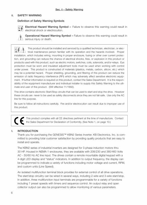
Electrical Hazard Warning Symbol – Failure to observe this warning could result inelectrical shock or electrocution.
Operational Hazard Warning Symbol – Failure to observe this warning could result inserious injury or death.
ii. SAFETY WARNING
!
This product should be installed and serviced by a qualified technician, electrician, or elec-trical maintenance person familiar with its operation and the hazards involved. Proper
installation, which includes wiring, mounting in proper enclosure, fusing or other over current protec-tion, and grounding can reduce the chance of electrical shocks, fires, or explosion in this product orproducts used with this product, such as electric motors, switches, coils, solenoids, and/or relays. Eyeprotection must be worn and insulated adjustment tools must be used when working with controlunder power. This product is constructed of materials (plastics, metals, carbon, silicon, etc.) whichmay be a potential hazard. Proper shielding, grounding, and filtering of this product can reduce theemission of radio frequency interference (RFI) which may adversely affect sensitive electronic equip-ment. If further information is required on this product, contact the Sales Department. It is the respon-sibility of the equipment manufacturer and individual installer to supply this Safety Warning to the ulti-mate end user of this product. (SW effective 11/1992).
This drive contains electronic Start/Stop circuits that can be used to start and stop the drive. Howeverthese circuits are never to be used as safety disconnects since they are not fail-safe. Use only the ACline for this purpose.
Be sure to follow all instructions carefully. Fire and/or electrocution can result due to improper use ofthis product.
!
This product complies with all CE directives pertinent at the time of manufacture. Contactthe Sales Department for Declaration of Conformity. (See Note 1, on page 10.)
Sec. ii – Safety Warning

Analog input signal following for 0 - 5 VDC, 0 - 10 VDC, 0 - 20 mADC, 4 - 20 mADC, andcustom input signals are also provided.
Other features include custom accel/decel curves, DC injection and dynamic braking,auto/manual restart, and 0 - 400 Hz operation, 1 - 12 kHz switching frequency, slip compen-sation, and PC Windows® based RS-232/485 DriveLink™ communications.
The KBN2 contains protection features designed to prevent drive and/or motor failure due tooverload, phase-to-phase and phase-to-ground short circuit, over voltage, undervoltage,and overtemperature. The fault codes are shown in the digital display. All models are ULapproved (USA and Canada) and 0.5 - 3 HP @ 230 Volts AC and all 460 Volt AC models areCE and C-tick (N10980) approved.
STANDARD FEATURES
• Digital Keypad with 4-Digit LED Display and Status Indicators – Used for drive opera-tion (Start/Stop, Forward/Reverse, and Frequency change), programming, and providesindication of drive status (Frequency, Custom Units, Functions, Fault Codes). Containsbuilt-in Speed Potentiometer.
• Regenerative and DC Injection Braking – Provides controlled rapid stopping.
• Barrier Terminal Blocks – Separate terminal blocks for power (AC line, motor) and exter-nal signal input wiring (potentiometer, multifunction input/output terminals, voltage/currentfollowing).
• 3 Multifunction Control Inputs – Provides selection of 7 Preset Speeds, Jog, Stop, and11 other functions.
• External Forward-Stop-Reverse Control – Provides external control of motor directionand run/stop (Forward/Stop, Reverse/Stop and Run/Stop, Forward/Reverse), and 3-wirestart/stop.
• Isolated External Signal Inputs – Provides isolated terminals for external signals to con-trol the drive output frequency (5 kΩ potentiometer, 0 - 5 VDC, 0 - 10 VDC, 0 - 5 VDC,0 - 20 mADC, 4 - 20 mADC). Functions F026 - F029 are used to scale the drive for awide range of input signals.
• Multifunction Output Relay – Provides normally open or normally closed relay contactsfor indication of Auto Start, Power Loss, Rapid Stop, Coast-to-Stop, Overtorque, andElectronic Overload Protection.
• Output Frequency Upper Limit – Provides adjustment of output frequency upper limit(0.01 - 400.0 Hz).
• Output Frequency Lower Limit – Provides adjustment of output frequency lower limit(0.00 - 400.0 Hz).
• Acceleration and Deceleration Time – Provides adjustment of acceleration and deceler-ation time (0.1 - 3600 seconds). A second acceleration and deceleration time is availableusing the multifunction input terminals.
7
Sec. I – Introduction (Cont.)
Sec. I – Introduction (Cont.)
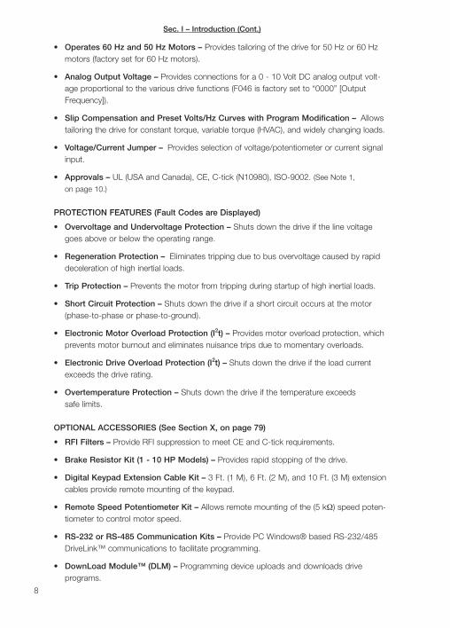
• Operates 60 Hz and 50 Hz Motors – Provides tailoring of the drive for 50 Hz or 60 Hzmotors (factory set for 60 Hz motors).
• Analog Output Voltage – Provides connections for a 0 - 10 Volt DC analog output volt-age proportional to the various drive functions (F046 is factory set to “0000” [OutputFrequency]).
• Slip Compensation and Preset Volts/Hz Curves with Program Modification – Allowstailoring the drive for constant torque, variable torque (HVAC), and widely changing loads.
• Voltage/Current Jumper – Provides selection of voltage/potentiometer or current signalinput.
• Approvals – UL (USA and Canada), CE, C-tick (N10980), ISO-9002. (See Note 1,
on page 10.)
PROTECTION FEATURES (Fault Codes are Displayed)
• Overvoltage and Undervoltage Protection – Shuts down the drive if the line voltagegoes above or below the operating range.
• Regeneration Protection – Eliminates tripping due to bus overvoltage caused by rapiddeceleration of high inertial loads.
• Trip Protection – Prevents the motor from tripping during startup of high inertial loads.
• Short Circuit Protection – Shuts down the drive if a short circuit occurs at the motor(phase-to-phase or phase-to-ground).
• Electronic Motor Overload Protection (I2t) – Provides motor overload protection, whichprevents motor burnout and eliminates nuisance trips due to momentary overloads.
• Electronic Drive Overload Protection (I2t) – Shuts down the drive if the load currentexceeds the drive rating.
• Overtemperature Protection – Shuts down the drive if the temperature exceedssafe limits.
OPTIONAL ACCESSORIES (See Section X, on page 79)
• RFI Filters – Provide RFI suppression to meet CE and C-tick requirements.
• Brake Resistor Kit (1 - 10 HP Models) – Provides rapid stopping of the drive.
• Digital Keypad Extension Cable Kit – 3 Ft. (1 M), 6 Ft. (2 M), and 10 Ft. (3 M) extensioncables provide remote mounting of the keypad.
• Remote Speed Potentiometer Kit – Allows remote mounting of the (5 kΩ) speed poten-tiometer to control motor speed.
• RS-232 or RS-485 Communication Kits – Provide PC Windows® based RS-232/485DriveLink™ communications to facilitate programming.
• DownLoad Module™ (DLM) – Programming device uploads and downloads driveprograms.
8

9
TABLE 1 – MODEL NUMBER IDENTIFICATION
KBN2
Series
– 2 2 01 – 1
InputVoltage
2: 230V4: 460V
InputPhase
2: 1φ, 3φ3: 3φ
EnclosureType
1: NEMA-1
Horsepower
50: 0.5 HP01: 1 HP02: 2 HP03: 3 HP05: 5 HP
07: 7.5 HP10: 10 HP15: 15 HP20: 20 HP30: 30 HP
Description Specification Factory Setting
AC Line Input Voltage (VAC) 208/230 (-10%, +15%), 380 - 460 (±10%) 220.0 / 460.0
Input AC Line Frequency Range (Hz) 48 - 62 —
Output Waveform Sine Coded PWM —
Frequency Range (Hz) 0.01 - 400.0 60
Switching Frequency Range (kHz) 1 - 12 10
Frequency Resolution (Hz Increments) 0.01 up to 100 Hz and 0.1 above 100 Hz —
Acceleration/Deceleration Range (Seconds) 0.1 - 3600 5
Overvoltage Trip Point @ 230 VAC, @ 460 VAC (VAC)1 290, 580 —
Undervoltage Trip Point @ 230 VAC, @ 460 VAC (VAC)1 140, 280 —
Overload Rating (% for 1 Minute) 150 —
Output Frequency Lower Limit Range (Hz) 0.0 - 400.0 0
Output Frequency Upper Limit Range (Hz) 1.0 - 400.0 60
Braking Torque without Braking Resistor (%) 20 20
Braking Torque with Braking Resistor (%) 2 20 - 100 20
Operating Temperature Range (ºC) -10 to 50 3 —
Humidity (Relative, Non-Condensing) (%) 0 - 95 —
Maximum Vibration (G) 0.5 —
Output Relay Contact Rating (Terminals 1, 2) 1 Amp @ 30 Volts DC, 250 Volts AC —
Open Collector Output Rating (Terminals 10, 11) 5 mA at 35 VDC —
External Analog Signal Input0 - 5 VDC, 0 - 10 VDC, 0 - 20 mADC,
4 - 20 mADC 4, Scalable0 - 10 VDC
External Speed Potentiometer (Ω) 5k or 10k —
Analog Output Voltage (Volts DC)5 0 - 10 —
TABLE 2 – GENERAL PERFORMANCE SPECIFICATIONS
Notes: 1. Based on 230/460 Volts nominal AC line input voltage. 2. Models KBN2-2250-1, 2201-1, 2202-1, 2203-1, 2305-1,2307-1, 2310-1, 4301-1, 4302-1, 4303-1, 4305-1, 4307-1, 4310-1 require optional Brake Resistor to achieve maximum braking.Braking resistor option is not available on other models. 3. In order to achieve 50 C maximum ambient temperature at full drive rating,the top dust cover on all models thru 10 HP must be removed. Drive rating with the cover installed is 40 C. 4. To set the drive for4 - 20 mADC input, F011 must be set to “0002”, F027 must be set to “0020”, and the jumper must be installed in the “2-3” positionof Jumper JP1. 5. Proportional to the mode setting. See Section IX, Functions F045 and F046, on pages 62 and 63. (maximumallowable load current is 1 mADC)
Sec. I – Introduction (Cont.)
10
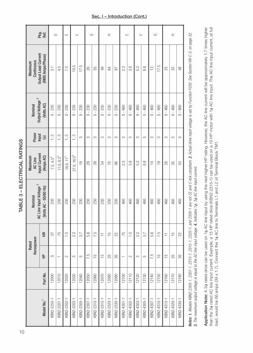
TAB
LE 3
– E
LEC
TR
ICA
L R
ATIN
GS
Note
s:1.
Mod
els
KBN2
-230
5-1,
2307
-1,2
310-
1,23
15-1
,232
0-1,
and
2330
-1 a
re n
ot C
E an
d C-
tick
com
plia
nt.2
.Act
ual d
rive
inpu
t vol
tage
is s
et b
y Fu
nctio
n F0
30.S
ee S
ectio
n VI
II-C-
3,on
pag
e 32
.3.
The
max
imum
out
put v
olta
ge is
equ
al to
the
AC li
ne in
put v
olta
ge.4
.Ind
icat
es 1
φ,3φ
AC li
ne in
put c
urre
nt.
Pkg.
Ref. D E F G H E F G H
Max
imum
Cont
inuo
usOu
tput
Loa
d Cu
rren
t(R
MS
Amps
/Pha
se)
3.1
4.5
7.5
10.5
17.5
26 35 49 64 87 2.3
3.8
5.2
8.8
13 17.5
25 32 48
Nom
inal
Outp
ut V
olta
ge 3
(Vol
ts A
C)
0 -
230
0 -
230
0 -
230
0 -
230
0 -
230
0 -
230
0 -
230
0 -
230
0 -
230
0 -
230
0 -
460
0 -
460
0 -
460
0 -
460
0 -
460
0 -
460
0 -
460
0 -
460
0 -
460
Phas
eIn
put
(φ)
1,3
1,3
1,3
1,3 3 3 3 3 3 3 3 3 3 3 3 3 3 3 3
Max
imum
AC L
ine
Inpu
t Cur
rent
(Am
ps A
C)
7.5,
4.54
11.0
,6.5
4
19.0
,114
27.0
,16.
04
19 29 39 54 70 96 2.3
3.8
5.2
8.8
14 19 28 35 53
Nom
inal
AC L
ine
Inpu
t Vol
tage
2
(Vol
ts A
C -
50/6
0 Hz
)
230
230
230
230
230
230
230
230
230
230
460
460
460
460
460
460
460
460
460
Rate
dHo
rsep
ower
kW .37
.75
1.5
2.2
3.7
5.6
7.5
11 15 22 .75
1.5
2.2
3.7
5.6
7.5
11 15 22
HP .5 1 2 3 5 7.5
10 15 20 30 1 2 3 5 7.5
10 15 20 30
Part
No.
1200
0
1201
0
1202
0
1203
0
1204
0
1205
0
1206
0
1207
0
1208
0
1209
0
1210
0
1211
0
1212
0
1213
0
1214
0
1215
0
1216
0
1217
0
1218
0
Mod
el N
o.1
KBN2
-225
0-1
KBN2
-220
1-1
KBN2
-220
2-1
KBN2
-220
3-1
KBN2
-230
5-1
KBN2
-230
7-1
KBN2
-231
0-1
KBN2
-231
5-1
KBN2
-232
0-1
KBN2
-233
0-1
KBN2
-430
1-1
KBN2
-430
2-1
KBN2
-430
3-1
KBN2
-430
5-1
KBN2
-430
7-1
KBN2
-431
0-1
KBN2
-431
5-1
KBN2
-432
0-1
KBN2
-433
0-1
Ap
plic
atio
n N
ote
:A
3φ
rate
d dr
ive
can
be u
sed
on 1
φA
C li
ne in
put
by u
sing
the
nex
t hi
gher
HP
rat
ing.
How
ever
, th
e A
C li
ne c
urre
nt w
ill be
app
roxi
mat
ely
1.7
times
hig
her
than
the
3φ
rate
d A
C li
ne in
put
curr
ent.
Exa
mpl
e, a
15
HP
rat
ed d
rive
(KB
N2-
2315
-1) c
an b
e us
ed o
n a
10 H
P m
otor
with
1φ
AC
line
inpu
t. Th
e A
C li
ne in
put
curr
ent,
at fu
lllo
ad,
wou
ld b
e 66
am
ps (3
9 x
1.7)
. C
onne
ct t
he 1
φA
C li
ne t
o Te
rmin
als
L1 a
nd L
2 of
Ter
min
al B
lock
TM
1.
Sec. I – Introduction (Cont.)

11
FREQ.SET0 100
STOP
REVFWD
FUN
RUN
SEQ
Hz/RPM
FRQ
ENTERREAD
NDOP-01
FUN
RESET
DSP
AMP
REVFWD
VOLT
3.7896
4.21107
5.91150
6.38162
5.31135
4 x ∅5.6
0.22
FIGURE 1A – MECHANICAL SPECIFICATIONS (Inches / mm)for Models KBN2-2250-1, 2201-1 (Pkg. D)
(Remove Top Cover for 50 ºC Rating)
FIGURE 1B – MECHANICAL SPECIFICATIONS (Inches / mm)for Models KBN2-2202-1, 4301-1, 4302-1 (Pkg. E)
(Remove Top Cover for 50 ºC Rating)
AMPFUN
ENTER100
FREQ.SET0
NDOP-01
REVFWD
STOPRUN
RESET
READ
DSPFUN
FWDSEQ
Hz/RPM
FRQ
VOLT
REV
4 x ∅ 0.225.6
5.43138
5.87149
6.85174
1847.24
6.02153
Sec. I – Introduction (Cont.)

12
FIGURE 1C – MECHANICAL SPECIFICATIONS (Inches / mm)for Models KBN2-2203-1, 2305-1, 4303-1, 4501-1 (Pkg. F)
(Remove Top Cover for 50 ºC Rating)
0 FR
EQ
.SE
T10
0
RE
AD
EN
TE
R
ND
OP
-01
FW
DS
EQ
FR
Q
RU
NS
TO
P
RE
VF
WD
Hz/
RP
M
FU
N
RE
V DS
PF
UN
RE
SE
TVO
LT
AM
P
4 x
∅5.
60.
2216
36.
42
8.03
204
8.46
215
174
6.85
185
7.28
Sec. I – Introduction (Cont.)
13
FR
EQ
.SE
TN
DO
P-0
110
0
RE
V
0
FW
D
RU
NS
TO
PSE
Q
FU
N
Hz/
RP
M
FR
Q
RE
SE
T
RE
AD
EN
TE
R
DS
PF
UN
RE
VF
WD
AM
P
VO
LT
4 x
∅6
0.24
11.8
130
0
11.2
628
6
7.32
186
7.87
200
7.83
199
FIGURE 1D – MECHANICAL SPECIFICATIONS (Inches / mm)for Models KBN2-2307-1, 2310-1, 4307-1, 4310-1 (Pkg. G)
(Remove Top Cover for 50 ºC Rating)
Sec. I – Introduction (Cont.)

100
FR
EQ
.SE
T0
RE
VF
WD
RE
AD
ND
OP
-01
EN
TE
R
RE
SE
T
FW
D
FU
N
RU
NS
TO
PSE
Q
Hz/
RP
M
FR
Q
AM
P
DS
PF
UNV
OL
T
RE
V
4 x
∅0.
28 7
9.45
240
15.7
540
0
15.1
638
5
9.29
236
9.84
250
14
FIGURE 1E – MECHANICAL SPECIFICATIONS (Inches / mm)for Models KBN2-2315-1, 2320-1, 2330-1, 4315-1, 4320-1, 4330-1 (Pkg. H)
Sec. I – Introduction (Cont.)
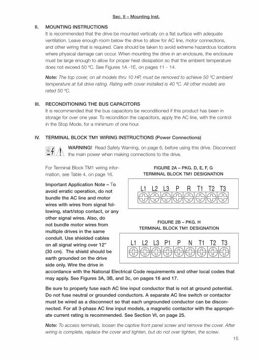
II. MOUNTING INSTRUCTIONSIt is recommended that the drive be mounted vertically on a flat surface with adequateventilation. Leave enough room below the drive to allow for AC line, motor connections,and other wiring that is required. Care should be taken to avoid extreme hazardous locationswhere physical damage can occur. When mounting the drive in an enclosure, the enclosuremust be large enough to allow for proper heat dissipation so that the ambient temperaturedoes not exceed 50 ºC. See Figures 1A -1E, on pages 11 - 14.
Note: The top cover, on all models thru 10 HP, must be removed to achieve 50 ºC ambienttemperature at full drive rating. Rating with cover installed is 40 ºC. All other models arerated 50 ºC.
III. RECONDITIONING THE BUS CAPACITORSIt is recommended that the bus capacitors be reconditioned if this product has been instorage for over one year. To recondition the capacitors, apply the AC line, with the controlin the Stop Mode, for a minimum of one hour.
IV. TERMINAL BLOCK TM1 WIRING INSTRUCTIONS (Power Connections)
WARNING! Read Safety Warning, on page 6, before using this drive. Disconnectthe main power when making connections to the drive.
For Terminal Block TM1 wiring infor-mation, see Table 4, on page 16.
Important Application Note – Toavoid erratic operation, do notbundle the AC line and motorwires with wires from signal fol-lowing, start/stop contact, or anyother signal wires. Also, donot bundle motor wires frommultiple drives in the sameconduit. Use shielded cableson all signal wiring over 12”(30 cm). The shield should beearth grounded on the driveside only. Wire the drive inaccordance with the National Electrical Code requirements and other local codes thatmay apply. See Figures 3A, 3B, and 3c, on pages 16 and 17.
Be sure to properly fuse each AC line input conductor that is not at ground potential.Do not fuse neutral or grounded conductors. A separate AC line switch or contactormust be wired as a disconnect so that each ungrounded conductor can be discon-nected. For all 3-phase AC line input models, a magnetic contactor with the appropri-ate current rating is recommended. See Section VI, on page 25.
Note: To access terminals, loosen the captive front panel screw and remove the cover. Afterwiring is complete, replace the cover and tighten, but do not over tighten, the screw.
15
!
P RL3L1 L2 T1 T2 T3
FIGURE 2A – PKG. D, E, F, GTERMINAL BLOCK TM1 DESIGNATION
L1 L2 L3 P1 P N T1 T2 T3
FIGURE 2B – PKG. HTERMINAL BLOCK TM1 DESIGNATION
Sec. II – Mounting Inst.

Sec. IV – Term. Block TM1 Wiring Inst. (Cont.)
A. AC Line Connection – Wirethe AC line to Terminals L1,L2 (for single phase AC line)or to Terminals L1, L2, L3(for 3-phase AC line) ofTerminal Block TM1, asshown in Figures 3A, 3B,and 3C, on page 17.
Notes: 1. The drive ratedAC line voltage (208/230,380/460 Volts AC) mustmatch the actual AC lineinput voltage, as describedin Section VIII-C-3, on page32. 2. If one of the AC lineinputs is a neutral (N), wireit to Terminal L2.
B. Ground Connection –Connect the ground wire(earth) to the ground screwas shown in Figures 3A, 3B,and 3C, on page 17.
16
Pkg. Model No. Part No.Maximum Wire Size (Cu) Recommended Tightening Torque
AWG mm2 in-lbs kg-cm
DKBN2-2250-1 12000
16 1.3 8.5 10KBN2-2201-1 12010
E
KBN2-2202-1 12020
14 2.1 8.5 10KBN2-4301-1 12100
KBN2-4302-1 12110
F
KBN2-2203-1 12030
10 5.3 15.5 18KBN2-2305-1 12040
KBN2-4303-1 12120
KBN2-4305-1 12130
G
KBN2-2307-1 12050
10 5.3 15.5 15KBN2-2310-1 12060
KBN2-4307-1 12140
KBN2-4310-1 12150
H
KBN2-2315-1 120706 13.3 22 25
KBN2-2320-1 12080
KBN2-2330-1 12090 4 21.2 22 25
KBN2-4315-1 12160
6 13.3 22 25KBN2-4320-1 12170
KBN2-4330-1 12180
TABLE 4 – TERMINAL BLOCK TM1 WIRING INFORMATION
Brake ResistorOptionalGround
(Earth)3φ AC Induction Motor
Chassis L1 L2 L3 T2RP T1 T3
1φ AC Line Input
FIGURE 3A – PKG. D, E, FPOWER CONNECTIONS WITH 1φ AC LINE INPUT
3 φ AC Line InputBrake Resistor(Earth)
L2Chassis
For single phase AC line connection,use Terminals L1 and L2.
L1
Ground
T3T1 T2RL3 P
Optional 3 φ AC Induction Motor
FIGURE 3B – PKG. D, E, F, GPOWER CONNECTIONS WITH 3 φ AC LINE INPUT
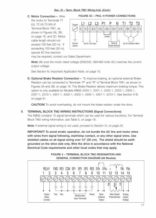
C. Motor Connection – Wirethe motor to Terminals T1(U), T2 (V),T3 (W) ofTerminal Block TM1, asshown in Figures 3A, 3B,on page 16, and 3C. Motorcable length should notexceed 100 feet (30 m). Ifexceeding 100 feet (30 m),special AC line reactorsmay be required, contact our Sales Department.
Note: Be sure the motor rated voltage (208/230, 380/460 Volts AC) matches the controloutput voltage.
See Section IV, Important Application Note, on page 15.
D. Optional Brake Resistor Connection – To improve braking, an optional external BrakeResistor can be connected to Terminals “P” and “R” of Terminal Block TM1, as shown inFigures 3A and 3B, on page 16. This Brake Resistor allows maximum braking torque. Thisoption is only available for Models KBN2-2250-1, 2201-1, 2202-1, 2203-1, 2305-1,2307-1, 2310-1, 4301-1, 4302-1, 4303-1, 4305-1, 4307-1, 4310-1. See Section X-B,on page 81.
CAUTION! To avoid overheating, do not mount the brake resistor under the drive.
V. TERMINAL BLOCK TM2 WIRING INSTRUCTIONS (Signal Connections)The KBN2 contains 15 signal terminals which can be used for various functions. For TerminalBlock TM2 wiring information, see Table 5, on page 18.
Note: If external signal wiring is not used, proceed to Section VI, on page 25.
IMPORTANT! To avoid erratic operation, do not bundle the AC line and motor wireswith wires from signal following, start/stop contact, or any other signal wires. Useshielded cables on all signal wiring over 12” (30 cm). The shield should be earthgrounded on the drive side only. Wire the drive in accordance with the NationalElectrical Code requirements and other local codes that may apply.
17
Brake Module(Earth)Ground 3 φ AC Line Input 3 φ AC Induction MotorOptional
Jumper
Chassis P1L2L1 L3 P N T1 T3T2
+-
FIGURE 3C – PKG. H POWER CONNECTIONS
SP16
Output FwdRelay
Rev
RELAY1 2 3
FWD5
COM4
REV
Reset
High
Wip
er
Low
SYN+RESSP2 SP37 8 9 10
SYN-11 14
FM-1312
+15FM+
ContactCollectorOutput
Open
Input TerminalsMultifunction Main Speed
PotentiometerAnalogOutputVoltage
+-+-
FIGURE 4 – TERMINAL BLOCK TM2 DESIGNATION ANDGENERAL CONNECTION DIAGRAM (All Models)
Sec. IV – Term. Block TM1 Wiring Inst. (Cont.)

Notes: 1. Terminal “5” is the “Common” for theStart/Stop circuit and the Multifunction Input Terminals.The maximum allowable load current is 20 mADC. 2.All terminals of Terminal Block TM2 are isolated fromthe AC line and motor wiring. This eliminates the need forisolated input signals. 3. Function codes are sometimesrepresented with one or more “x”. An “x” is used whenthe code is used for functions other than the functionpresently discussed (example: xx01).
A. External Run/Stop Forward/Reverse Connection –External control of Run/Stop and Forward/Reverse isachieved by wiring contacts to Terminals 3, 4, 5, and6 as shown in Figures 5A - 5D. To program the drivefor external Run/Stop, set Function F010 to “0001”[External Contacts]. The settings for externalRun/Stop control using F003 are shown inTable 6, on page 19.
The drive is factory programmed for Forward/Stop usingTerminal 3 and Reverse/Stop using Terminal 4. To programthe drive for Run/Stop using Terminal 3 and Forward/Reverse using Terminal 4, set F003 to “xx01”. For 3-wireStart/Stop, set Function F003 to “XX10”. See SectionVIII-D-2, on page 33for programminginformation.
WARNING!The Stop
Contact is never tobe used as a SafetyDisconnect since itis not fail-safe. Useonly the AC line forthis purpose.
18
Application Note – Although this section covers the wiring of Terminal Block TM2, therespective programming functions are also presented. Function programming is also coveredin Drive Operation, in Section VIII, on page 27. Also see the Programmable Functions(Detailed), Section IX, starting on page 55.
DescriptionMaximum Wire Size (Cu) Recommended Tightening Torque
AWG mm2 in-lbs kg-cm
All Signal Input and Outputs (Terminals 1 - 15) 18 0.8 5 6
TABLE 5 – TERMINAL BLOCK TM2 WIRING INFORMATION (All Models)
Fwd/Stop
Rev/Stop
FWD REV COM3 4 5
FIGURE 5A
FORWARD/STOP-REVERSE/STOP
CONNECTION (Maintained Contacts)
(F003 Set to “xx00”) (Factory Setting)
Fwd/Rev
Run/Stop
43 5FWD REV COM
FIGURE 5B
RUN/STOP-FORWARD/REVERSE
CONNECTION (Maintained Contacts)
(F003 Set to “xx01”)
Stop
Start Close toReverse
43 5FWD REV COM SP1
6
FIGURE 5D – 3-WIRE START/STOP
CONNECTION WITH REVERSE
(Momentary Contacts)
(F003 Set to “xx10”)
(Use a Maintained Contact
for Reverse)
Start
Stop
43 5FWD REV COM
FIGURE 5C
3-WIRE START/STOP
CONNECTION
(Momentary Contacts)
(F003 Set to “xx10”)!
Sec. V – Term. Block TM2 Wiring Inst. (Cont.)
Sec. V – Term. Block TM2 Wiring Inst. (Cont.)
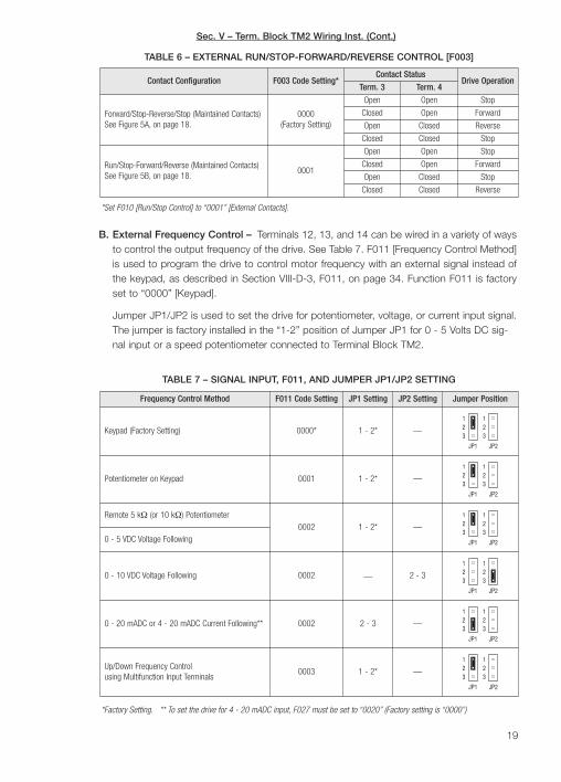
B. External Frequency Control – Terminals 12, 13, and 14 can be wired in a variety of waysto control the output frequency of the drive. See Table 7. F011 [Frequency Control Method]is used to program the drive to control motor frequency with an external signal instead ofthe keypad, as described in Section VIII-D-3, F011, on page 34. Function F011 is factoryset to “0000” [Keypad].
Jumper JP1/JP2 is used to set the drive for potentiometer, voltage, or current input signal.The jumper is factory installed in the “1-2” position of Jumper JP1 for 0 - 5 Volts DC sig-nal input or a speed potentiometer connected to Terminal Block TM2.
19
Contact Configuration F003 Code Setting*Contact Status
Drive OperationTerm. 3 Term. 4
Forward/Stop-Reverse/Stop (Maintained Contacts)See Figure 5A, on page 18.
0000(Factory Setting)
Open Open Stop
Closed Open Forward
Open Closed Reverse
Closed Closed Stop
Run/Stop-Forward/Reverse (Maintained Contacts)See Figure 5B, on page 18.
0001
Open Open Stop
Closed Open Forward
Open Closed Stop
Closed Closed Reverse
TABLE 6 – EXTERNAL RUN/STOP-FORWARD/REVERSE CONTROL [F003]
*Set F010 [Run/Stop Control] to “0001” [External Contacts].
Frequency Control Method F011 Code Setting JP1 Setting JP2 Setting Jumper Position
Keypad (Factory Setting) 0000* 1 - 2* —
Potentiometer on Keypad 0001 1 - 2* —
Remote 5 kΩ (or 10 kΩ) Potentiometer0002 1 - 2* —
0 - 5 VDC Voltage Following
0 - 10 VDC Voltage Following 0002 — 2 - 3
0 - 20 mADC or 4 - 20 mADC Current Following** 0002 2 - 3 —
Up/Down Frequency Controlusing Multifunction Input Terminals
0003 1 - 2* —
TABLE 7 – SIGNAL INPUT, F011, AND JUMPER JP1/JP2 SETTING
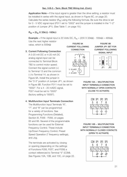
*Factory Setting. ** To set the drive for 4 - 20 mADC input, F027 must be set to “0020” (Factory setting is “0000”)

Sec. V-B – Term. Block TM2 Wiring Inst. (Cont.)
Application Note – The KBN2 can be programmed to accept awide range of voltage or current input signals using FunctionsF026 - F029, as described in Section VIII-D-4, on pages 35 - 37.
Location of Jumper JP1/JP2: To access Jumper JP1/JP2,loosen the captive front panel screw and lift off the cover.The jumper is located above Terminal Block TM2, as shownin Figure 6.
1. Remote Speed PotentiometerConnection – A 5 kΩ (or 10 kΩ)remote speed potentiometer canbe connected to Terminal BlockTM2 to control motor speed.Connect the high side of thepotentiometer to Terminal 12, thewiper to Terminal 13, and the lowside to Terminal 14, as shown inFigure 7A. Set F011 [FrequencyControl Method] to “0002” andbe sure the jumper is installed inthe “1-2” position of Jumper JP1(factory setting), as shown inFigure 7B. (See Section VIII-D-3,on page 34.
2. Voltage Following Connection –A 0 - 5 or 0 -10 Volt DC analogsignal input can be connected toTerminal Block TM2 to controlmotor speed. Connect the signalvoltage (+) to Terminal 13 and thecommon (-) to Terminal 14, asshown in Figure 8A. Set F011[Frequency Control Method] to“0002” [Analog Signal]. For 0 - 5Volt DC analog signal voltage, besure the jumper is installed in the “1-2” position (factorysetting) of Jumper JP1. For 0 - 10 Volt DC analog sig-nal voltage, install the jumper in the “2-3” position ofJumper JP2, as shown in Figure 8B.
Notes: 1. F011 [Frequency Control Method] is factoryset to “0000” [Keypad]. 2. Functions F026, F027, andF028 can be used to rescale the drive for other inputsignals. 3. Input impedance of Terminal 13 is 20 kΩ.
20
High
Wip
er
Low
Main SpeedPotentiometer
+ FM-12 13 14
FIGURE 7A
REMOTE SPEED
POTENTIOMETER
CONNECTION
FIGURE 7B
JUMPER JP1 SET FOR
EXTERNAL SPEED
POTENTIOMETER
(FACTORY SETTING)
+
-
0 - 10 VDC V
13 14FM-
12+
FIGURE 8A
VOLTAGE FOLLOWING
CONNECTION
FIGURE 8B
JP2 SET FOR 0 - 10 VDC
VOLTAGE FOLLOWING
SIGNAL OUTPUT
9 121110
23 3
21 1
JP1 JP2
FIGURE 6 – TYPICAL
LOCATION OF
JUMPER JP1/JP2
+
-
V R INSourceVoltage
+ FM-1412 13
FIGURE 8C – VOLTAGE
FOLLOWING CONNECTION
WITH SERIES RESISTOR
Sec. V-B-2 – Term. Block TM2 Wiring Inst. (Cont.)
Application Note – If the input signal is greater than the drive setting, a resistor mustbe installed in series with the signal input, as shown in Figure 8C, on page 20.Calculate the series resistor (RIN) using the following formula. Be sure the drive is setfor 0 - 5 VDC signal input (F011 set to “0002” and the jumper is installed in the “1-2”position of Jumper JP1). (See Table 7, on page 19.)
RIN = (VIN X 33kΩ) -165kΩ
Example – If the signal input is 20 Volts DC, RIN = (20V X 33kΩ) - 165kΩ = 495kΩ.Use the next higher resistorvalue, which is 500kΩ
3. Current Following ConnectionA 0-20 mA DC or 4-20 mA DCanalog signal input can beconnected to Terminal BlockTB2 to control motor speed.Connect the signal current (+)to Terminal 13 and the common(-) to Terminal 14, as shown inFigure 9A. Install the jumper inthe “2-3” position of Jumper JP1, as shownin Figure 9B. Function F011 must be set to“0002”. For a 4 - 20 mADC signal,F027 must be set to “0020”(factory setting is “0000”).
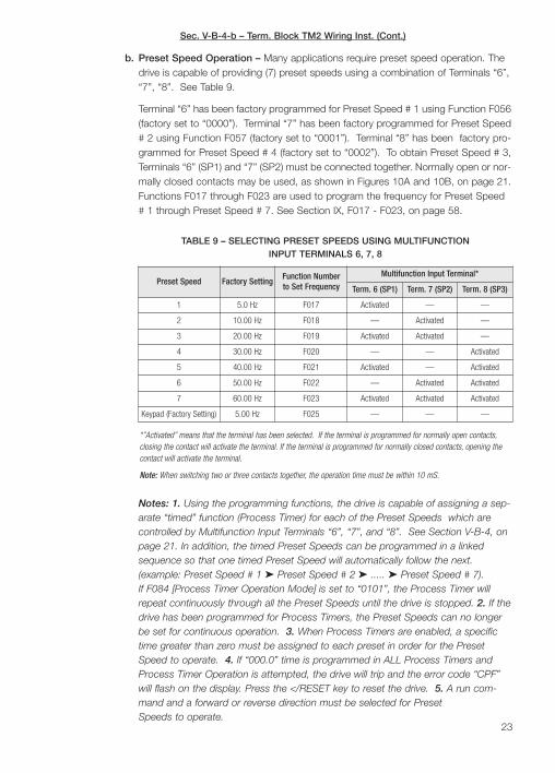
4. Multifunction Input Terminals ConnectionThe Multifunction Input Terminals “6”,“7”, and “8” can be programmedfor a variety of functions. SeeProgramming Functions (Detailed),Section IX, F056 - F058, on pages65 and 66. Several of the programmablefunctions can be used for ExternalFrequency Control. These includeUp/Down Frequency Control, PresetSpeed Operation (7 frequency settings),and Jog.
The terminals are activated by closingor opening (depending on the settingsof Functions F056, F057, and F058) acontact referenced to Terminal “5” (COM).See Figures 10A, 10B, and 10C, on page 22.
21
-
+
or0 - 20 mADC
4 - 20 mADC
+ FM-1412 13
FIGURE 9A
CURRENT FOLLOWING
CONNECTION
FIGURE 9B
JUMPER JP1 SET FOR
CURRENT FOLLOWING
SIGNAL INPUT
5COM
6SP1
7SP2
8SP3
FIGURE 10A – MULTIFUNCTION
INPUT TERMINALS CONNECTION
WITH NORMALLY OPEN CONTACTS
(CLOSE TO ACTIVATE)
SP27
SP165
COM SP38
FIGURE 10B – MULTIFUNCTION
INPUT TERMINALS CONNECTION
WITH NORMALLY CLOSED CONTACTS
(OPEN TO ACTIVATE)

Sec. V-B-4-a – Term. Block TM2 Wiring Inst. (Cont.)
a. External Up/Down Frequency Control –External contacts can be used to simulatethe and keys on the digital keypad.Any two of Terminals 6, 7, and 8 can beprogrammed for Up/Down Frequency Controlusing Functions F056, F057 (or F058). Seefigures 11A, 11B, and 11C.
To program Terminal 6 for Up Control usingnormally open contacts, set Function F056 to“0012”. (To program Terminal 6 for Up Controlusing normally closed contacts, set FunctionF056 to “0028”.) The incremental rate ofchange of the Up Control for frequency setting, using external contacts, is propor-tional to the Acceleration Time #1 setting [F001].
To program Terminal 7 for Down Control using normally open contacts, set FunctionF057 to “0013”. (To program Terminal 7 for Down Control using normally closedcontacts, set Function F057 to “0029”.) The incremental rate of change of theDown Control for frequency setting, using external contacts, is proportional to theDeceleration Time # 1 setting [F002].
Note: For Up/Down Frequency Control using the Multifunction Input Terminals,Function F011 must be set to “0003” [Up/Down Frequency Control].
22
SP27
SP165
COM SP38
FIGURE 10C – MULTIFUNCTION
INPUT TERMINALS CONNECTION
WITH OPEN COLLECTOR
FunctionNumber
Function Description Code Code Description
F011 Frequency Control Method 0003 (Factory Setting is “0000”) Up/Down Frequency Control
F056 Multifunction Input Terminal 6 (SP1) 0012 (Factory Setting is “0000”) Up Command
F057 Multifunction Input Terminal 7 (SP2) 0013 (Factory Setting is “0001”) Down Command
TABLE 8 – SETTINGS FOR EXTERNAL UP/DOWN FREQUENCY CONTROL
Up Down
SP27
SP165
COM
FIGURE 11A – UP/DOWN
FREQUENCY CONTROL
CONNECTION
WITH NORMALLY
OPEN CONTACTS
COM
Up
5
Down
SP1 SP26 7
FIGURE 11B – UP/DOWN
FREQUENCY CONTROL
CONNECTION
WITH NORMALLY
CLOSED CONTACTS
SP27
SP165
COM
DownUp
FIGURE 11C – UP/DOWN
FREQUENCY CONTROL
CONNECTION WITH
OPEN COLLECTOR
Sec. V-B-4-b – Term. Block TM2 Wiring Inst. (Cont.)
Notes: 1. Using the programming functions, the drive is capable of assigning a sep-arate “timed” function (Process Timer) for each of the Preset Speeds which arecontrolled by Multifunction Input Terminals “6”, “7”, and “8”. See Section V-B-4, onpage 21. In addition, the timed Preset Speeds can be programmed in a linkedsequence so that one timed Preset Speed will automatically follow the next.(example: Preset Speed # 1 Preset Speed # 2 ..... Preset Speed # 7).If F084 [Process Timer Operation Mode] is set to “0101”, the Process Timer willrepeat continuously through all the Preset Speeds until the drive is stopped. 2. If thedrive has been programmed for Process Timers, the Preset Speeds can no longerbe set for continuous operation. 3. When Process Timers are enabled, a specifictime greater than zero must be assigned to each preset in order for the PresetSpeed to operate. 4. If “000.0” time is programmed in ALL Process Timers andProcess Timer Operation is attempted, the drive will trip and the error code “CPF”will flash on the display. Press the </RESET key to reset the drive. 5. A run com-mand and a forward or reverse direction must be selected for PresetSpeeds to operate.
23
b. Preset Speed Operation – Many applications require preset speed operation. Thedrive is capable of providing (7) preset speeds using a combination of Terminals “6”,“7”, “8”. See Table 9.
Terminal “6” has been factory programmed for Preset Speed # 1 using Function F056(factory set to “0000”). Terminal “7” has been factory programmed for Preset Speed# 2 using Function F057 (factory set to “0001”). Terminal “8” has been factory pro-grammed for Preset Speed # 4 (factory set to “0002”). To obtain Preset Speed # 3,Terminals “6” (SP1) and “7” (SP2) must be connected together. Normally open or nor-mally closed contacts may be used, as shown in Figures 10A and 10B, on page 21.Functions F017 through F023 are used to program the frequency for Preset Speed# 1 through Preset Speed # 7. See Section IX, F017 - F023, on page 58.
Preset Speed Factory SettingFunction Numberto Set Frequency
Multifunction Input Terminal*
Term. 6 (SP1) Term. 7 (SP2) Term. 8 (SP3)
1 5.0 Hz F017 Activated — —
2 10.00 Hz F018 — Activated —
3 20.00 Hz F019 Activated Activated —
4 30.00 Hz F020 — — Activated
5 40.00 Hz F021 Activated — Activated
6 50.00 Hz F022 — Activated Activated
7 60.00 Hz F023 Activated Activated Activated
Keypad (Factory Setting) 5.00 Hz F025 — — —
TABLE 9 – SELECTING PRESET SPEEDS USING MULTIFUNCTIONINPUT TERMINALS 6, 7, 8
*”Activated” means that the terminal has been selected. If the terminal is programmed for normally open contacts,closing the contact will activate the terminal. If the terminal is programmed for normally closed contacts, opening thecontact will activate the terminal.
Note: When switching two or three contacts together, the operation time must be within 10 mS.
Sec. V-B-4-c – Term. Block TM2 Wiring Inst. (Cont.)
c. Jog Speed Operation – The drive provides selection for a “jog” speed. To selectthe jog frequency which is programmed in Function F024 (factory setting is 2.00Hz), wire normally open or normally closed contacts to one of the MultifunctionInput Terminals. To program one of the Multifunction Input Terminals for Jog usingnormally open contacts, set Function F056, F057, or F058 to “0003”. To programone of the Multifunction Input Terminals for Jog using normally closed contacts, setFunction F056, F057, or F058 to “0019”
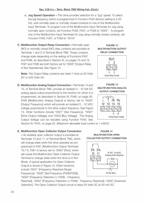
C. Multifunction Output Relay Connection – Normally open(NO) or normally closed (NC) relay contacts are provided atTerminals 1 and 2 of Terminal Block TM2. These contactschange state depending on the setting of Functions F097and F098, as described in Section IX, on pages 72 and 73.F097 and F098 are both factory set to “0000” [Output Relayis Not Operational]. See Figure 12.
Note: The Output Relay contacts are rated 1 Amp at 30 VoltsDC or 250 Volts AC.
D. Multifunction Analog Output Connection – Terminals 14 and15, of Terminal Block TM2, provide an isolated 0 - 10 Volt DCanalog signal output proportional to the function for which it isprogrammed, as described in Section IX, F046, on page 63.F046 [Multifunction Analog Output] is factory set to “0000”[Output Frequency] which will provide an isolated 0 - 10 VDCvoltage proportional to the drive output frequency. See Figure13. Other functions include “0001” [Set Frequency], “0002”[Drive Output Voltage], and “0003 [Bus Voltage]. The AnalogOutput Voltage can be rescaled using Function F045. SeeSection IX, F045, on page 62. (Maximum allowable load current is 1 mADC)
E. Multifunction Open Collector Output Connection– An isolated open collector output is provided atTerminals 10 and 11, of Terminal Block TM2, whichwill change state when the drive operates as pro-grammed in F061 [Multifunction Output Terminals10,11]. F061 is factory set to “0000” [Run], whichwill cause the Multifunction Open Collector OutputTerminal to change state when the drive is in RunMode. A typical application for Open CollectorOutput is shown in Figure 14. Other functionsinclude “0001” [Frequency Reached (TargetFrequency)], “0002” [Set Frequency (F008/F009)],“0003” [Frequency Detection (> F008) - FrequencyReached], “0004” [Frequency Detection (< F008) - Frequency Reached], “0005” [OverloadDetection]. The Open Collector Output circuit is rated 35 Volts DC at 50 mA DC.
24
RELAY1 2
Output Relay Contact
FIGURE 12
MULTIFUNCTION OUTPUT
RELAY CONNECTION
FM+15
- +
Analog Output Voltage
12+
13 14FM-
FIGURE 13
MULTIFUNCTION ANALOG
OUTPUT CONNECTION
SYN+SYN–1110
35 VDC (Max.)
35 VDC - 50 mADCClamping Diode (Required)
+-
Relay
FIGURE 14
MULTIFUNCTION OPEN
COLLECTOR OUTPUT CONNECTION

F. Reset Connection – A nor-mally open momentary con-tact can be connected toTerminals 5 and 9, ofTerminal Block TM2, toreset the drive after a faulthas cleared, as shown inFigure 15. (Also see SectionIX, F016, on page 57).
G. RS-232 or RS-485 Communication Cable Connection –When installing the optional RS-232 or RS-485Communication Cable, remove the jumper that is installed on CON12. CON12 is locatedabove Terminal Block TM2. Be sure the factory installed jumper is in the “1-2” position ofCON12, if not using RS-232 or RS-485 communications. RS-232 or RS-485 is used toprogam the drive using a PC. The Download Module (DLM) can also be used to programthe drive. See Section X-E, on page 79.
VI. AC LINE FUSINGThis drive does not contain AC line input fuses. Most electrical codes require that eachungrounded conductor contain circuit protection. Install a fuse or circuit breaker in series witheach ungrounded conductor. For all 3-phase AC line input models, a magnetic contactor withthe appropriate current rating is recommended. Do not fuse neutral or grounded conductors.See Table 10. Check all electrical codes that apply to the application. Do not install a fuse orcircuit breaker in series with motor leads.
VII. RECOMMENDED HIGH VOLTAGE DIELECTRIC WITHSTAND TESTING (Hi-Pot)Testing agencies such as UL, CSA, etc., usually require that the equipment undergo a hi-pottest. In order to prevent catastrophic damage to the drive, which has been installed in theequipment, it is recommended that the following procedure be followed. A typical hi-pot testsetup is shown in Figure 16, on page 26. All drives have been factory hi-pot tested in accor-dance with UL requirements.
Note: When performing the hi-pot test, disconnect the AC power. 25
COM5 8
SP36
SP17
SP29
RES
FIGURE 15A
RESET CONNECTION
COM5 8
SP36
SP17
SP2 RES9
FIGURE 15B
RESET CONNECTION
WITH OPEN COLLECTOR
Model Rating (Amps AC)
KBN2-2250-1 10, 5*
KBN2-2201-1 15, 10*
KBN2-2202-1 20, 10*
KBN2-2203-1 30, 15*
KBN2-2305-1 30
KBN2-2307-1 60
KBN2-2310-1 60
KBN2-2315-1 100
KBN2-2320-1 100
KBN2-2330-1 150
Model Rating (Amps AC)
KBN2-4301-1 5
KBN2-4302-1 10
KBN2-4303-1 15
KBN2-4305-1 20
KBN2-4307-1 40
KBN2-4310-1 40
KBN2-4315-1 70
KBN2-4320-1 70
KBN2-4330-1 100
TABLE 10 – RECOMMENDED FUSE, CIRCUIT BREAKER, OR MAGNETIC CONTACTOR RATING
* Rating is given for 1φ , 3 φ AC line input.
Sec. V-F – Term. Block TM2 Wiring Inst. (Cont.)

26
Adj
usta
ble
Fre
quen
cy D
rive
T3
Mac
hine
or
Equ
ipm
ent F
ram
e
All
AC
Lin
e In
puts
Con
nect
Hi-P
ot to
Aux
iliar
y E
quip
men
t
Cha
ssis
L2L1
T2
T1
RPL3L2L1
(Mai
n P
ower
Dis
conn
ecte
d)C
onne
ct A
ll T
M1
Ter
min
als
Tog
ethe
r
H. V
.R
ES
ET
AC
Lin
e In
put
RE
TU
RN
TE
ST
ZE
RO
MA
X
VO
LTA
GE
Hig
h V
olta
ge D
iele
ctric
With
stan
d T
este
r (H
i-Pot
Tes
ter)
LEA
KA
GE
0mA
10m
A
0
AC
KIL
OV
OLT
S
12
3
Mot
or W
ires
Cha
ssis
Fra
me
FIGURE 16 – HI-POT SETUP
Sec. VIII – Recommended High Voltage Dielectric Withstand Testing (Cont.)

CAUTION! To avoid damage to the drive, do not connect any terminals of Terminal BlockTM2 to the hi-pot tester.
A. Connect all equipment AC power input lines together and connect them to the H. V. leadof the hi-pot tester. Connect the RETURN lead of the hi-pot tester to the frame on whichthe control and other auxiliary equipment are mounted.
B. The hi-pot tester must have an automatic ramp-up to the test voltage and an automaticramp-down to zero voltage.
Note: If the hi-pot tester does not have automatic ramping, then the hi-pot output mustbe manually increased to the test voltage and then manually reduced to zero. This proce-dure must be followed for each machine to be tested. A suggested hi-pot tester isSlaughter Model 2550.
CAUTION! Instantaneously applying the hi-pot voltage will cause irreversibledamage to the drive.
VIII. DRIVE OPERATIONBefore operating this drive, read the following instruc-tions on Digital Keypad operation and programmingfunctions. See Figure 17, for the digital keypad layout.The display can indicate various functions of the drive:set frequency, motor RPM, output current and voltage,custom units, function numbers, function codes or val-ues, and fault codes.
If an error message appears while programming thedrive, see Table 22, on pages 74 - 76.
A. Digital Keypad Description – The digital keypad has7 keys which are used to program drive functions andcontrol various features, as described below. EightLEDs are provided to indicate the drive’s operationalstatus. A potentiometer is also provided on the key-pad to set drive frequency. See Figure 17. Note: To avoid damage, never operate thekeypad with a screwdriver or other sharp-ended tool.
Run/Stop Key – Starts or stops the drive. If the drive is stopped, press theRUN/STOP key to start the drive. F010 must be set to “0000” (factorysetting). If the drive is running, press the RUN/STOP key to stop the drive.
Forward/Reverse Key – Changes motor direction. If the drive is set to runthe motor in the forward direction, press the FWD/REV key change motordirection to reverse. The FWD LED will turn off, and the REV LED will illumi-
nate. If the drive is set to run the motor in the reverse direction, press the FWD/REV keyto change motor to forward. The REV LED will turn off, and the FWD LED will illuminate.F010 must be set to “0000” (factory setting).
27
!FIGURE 17 – DIGITAL
KEYPAD LAYOUT
Sec. VIII – Recommended High Voltage Dielectric Withstand Testing (Cont.)
Sec. VIII-A – Drive Operation (Cont.)
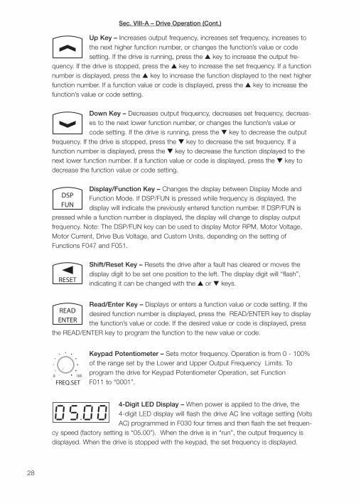
Up Key – Increases output frequency, increases set frequency, increases tothe next higher function number, or changes the function’s value or codesetting. If the drive is running, press the key to increase the output fre-
quency. If the drive is stopped, press the key to increase the set frequency. If a functionnumber is displayed, press the key to increase the function displayed to the next higherfunction number. If a function value or code is displayed, press the key to increase thefunction’s value or code setting.
Down Key – Decreases output frequency, decreases set frequency, decreas-es to the next lower function number, or changes the function’s value orcode setting. If the drive is running, press the key to decrease the output
frequency. If the drive is stopped, press the key to decrease the set frequency. If afunction number is displayed, press the key to decrease the function displayed to thenext lower function number. If a function value or code is displayed, press the key todecrease the function value or code setting.
Display/Function Key – Changes the display between Display Mode andFunction Mode. If DSP/FUN is pressed while frequency is displayed, thedisplay will indicate the previously entered function number. If DSP/FUN is
pressed while a function number is displayed, the display will change to display outputfrequency. Note: The DSP/FUN key can be used to display Motor RPM, Motor Voltage,Motor Current, Drive Bus Voltage, and Custom Units, depending on the setting ofFunctions F047 and F051.
Shift/Reset Key – Resets the drive after a fault has cleared or moves thedisplay digit to be set one position to the left. The display digit will “flash”,indicating it can be changed with the or keys.
Read/Enter Key – Displays or enters a function value or code setting. If thedesired function number is displayed, press the READ/ENTER key to displaythe function’s value or code. If the desired value or code is displayed, press
the READ/ENTER key to program the function to the new value or code.
Keypad Potentiometer – Sets motor frequency. Operation is from 0 - 100%of the range set by the Lower and Upper Output Frequency Limits. Toprogram the drive for Keypad Potentiometer Operation, set FunctionF011 to “0001”.
4-Digit LED Display – When power is applied to the drive, the4-digit LED display will flash the drive AC line voltage setting (VoltsAC) programmed in F030 four times and then flash the set frequen-
cy speed (factory setting is “05.00”). When the drive is in “run”, the output frequency isdisplayed. When the drive is stopped with the keypad, the set frequency is displayed.
28

B. Digital Keypad Operation – Examples of basic keypad operation are described below.
1. Setting Drive Output Frequency Using the Keypad – The drive is factory set to runat 5.00 Hz when the drive is in the Run Mode. (Press the RUN/STOP Key to start orstop the drive.)
a. To change the Set Frequency (drive in Stop Mode):
1. Press the </RESET key to move the setable digit to the left and the or keyuntil the desired frequency is displayed. Note: The setable digit will flash.
2. Press the RUN/STOP key to run the drive at the new Set Frequency.
Note: Figure 18, on page 30, is a flow chart which illustrates the sequence to changeand program the Set Frequency from 5.00 Hz to 43.21 Hz using the keypad.
b. To change the Run Frequency (drive in Run Mode):
1. Press the </RESET key to move the setable digit to the left and the or keyuntil the desired frequency is displayed. Note: The setable digit will flash.
2. Press the READ/ENTER key to run the drive at the new Set Frequency.
2. Programming the Drive – The drive contains many functions that can be programmedfor specific application. A summary list of all programmable functions is provided inTable 17, beginning on page 46.
29
When the FUN LED is illuminated, the display shows a Function Number and the driveis in Program Mode.
When the FWD LED is illuminated, the drive is set for Forward Direction.
When the Hz/RPM LED is illuminated, the display shows Frequency (in Hz) or RPM.
When the REV LED is illuminated, the drive is set for Reverse Direction.
When the SEQ LED is illuminated, the drive is set for External Run/Stop (F010 setto “0001”).
When the VOLT LED is illuminated, the display shows Motor voltage (Volts AC)[F047 = xxx1] or bus voltage (Volts DC) [FO47 = xx1x].
When the FRQ LED is illuminated, the drive is set for External Frequency Control orKeypad Potentiometer Control.
When the AMP LED is illuminated, the display shows Motor current (Amps AC)[F047 = x1xx].
LED Status Indicators – The drive is designed with 8 LEDs mounted on the digital key-pad to display the drive’s operational status, as described below. When power is appliedto the drive (in factory setting), the “VOLT”, and “FWD” LEDs will illuminate on the displayand the POWER LED, (located on the drive PC board, to the right of Terminal Block TM1)will also illuminate.
TABLE 11 – LED STATUS INDICATORS
Sec. VIII-A – Drive Operation (Cont.)

30
Set FrequencyFlashes 4 Times
Line Voltage Setting
Power On
Changeable Digit
for 5 SecondsChangeable Digit
Display FlashesPress 1 TimeFlashes
Press 1 Timeto Move
RESET
Changeable Digit
Display FlashesPress 2 Times
Flashes
RESET
to MovePress 2 Times Press 2 Times
Flashes for5 Seconds
Changeable Digit
the DrivePress To RunPress 4 TimesPress 3 Times
Changeable Digit
RESET
to Move
Display Flashes
Changeable Digit
(F025 Automaticallythe New SettingPress to Enter
Sets to "43.21")
Display Flashes
READENTER
is DisplayedNew Set Frequency
RUNSTOP
Function NumberDisplay
Press 5 Times
Changeable Digitto Move
Press 3 Times Changeable DigitFlashes
ChangeableDigit Flashes
Flashes 4 TimesLine Voltage Setting
Power On FUN
RESET
Set FrequencyFlashes Change Display
Press to
DSP
New Settingis Displayed
Press 1 Time Press to Enterthe New Setting
AccelerationTime # 1
Function Numberis Displayed
Momentarily
which ConfirmsNew Setting
Displayed DisplayPress to
Set Frequency
Set FrequencyFlashes
ENTER
Function Number
Press 1 Timeto Change
READENTER
AccelerationPress to Display
SettingTime # 1
READRESET
Time # 1Acceleration
is Displayed
DSPFUN
Changeable Digit
Press 3 Timesto Move
Changeable DigitFlashes
Function Numberis Displayed
Time # 1Acceleration
FIGURE 18 – FLOW CHART TO CHANGE SET FREQUENCY – Drive in STOP Mode
FIGURE 19 – FLOW CHART TO PROGRAM F001 (ACCELERATION TIME # 1)
Sec. VIII-B-2 – Drive Operation (Cont.)
Sec. VIII-B-2 – Drive Operation (Cont.)
Acceleration Time # 1 [F001] – Sets the acceleration time (seconds) of the drive.F001 can be changed while the drive is in Stop Mode or Run Mode.
Example – Figure 19, on page 30, illustrates the sequence to program F001 for a 500second acceleration time.
To change the setting of F001:
a. Press the DSP/FUN key to display Function Number.
b. Press the </RESET key to move the setable digit one position to the left and the or key until “F001” is displayed. Note: The setable digit will flash.
c. Press the READ/ENTER key. “010.0” seconds will be displayed (factory setting).
d. Press the </RESET key to move the setable digit one position to the left and the or key until the desired acceleration time is displayed. Note: The setable digit will flash.The programmable range is 0.1 - 3600 seconds. (Note: “000.0” cannot be set.)
e. Press the READ/ENTER key to “enter” the new acceleration time. “End” will bemomentarily displayed, which confirms the new acceleration time setting. “F001”will be displayed.
f. Press the DSP/FUN key to return to the frequency display or press the or keyto change to another function number.
C. Important Programming Functions – All drive functions have been factory programmed,as shown in Table 17, on page 46. Detailed descriptions of all programmable functions aregiven in Section IX, on page 53.
Function codes are sometimes represented with one or more “x”. An “x” is usedwhen the code is used for functions other than the function presently discussed(example: xx01).
1. Motor Current Rating [F070] – In order for the Motor Overload Protection Featureto be effective, Function F070 must be set to the motor nameplate current rating(Amps AC) if the actual motor current differs nominally from the factory setting.
Note: For the factory default setting for motor current, see Table 20, on page 68.
To enter the motor nameplate current rating into F070:
a. The drive must be in Stop Mode (press the RUN/STOP key).
b. Press the DSP/FUN key to display Function Number.
c. Press the </RESET key to move the setable digit one position to the left and the or key until “F070” is displayed. Note: The setable digit will flash.
d. Press the READ/ENTER key. The factory default setting of Motor Current Rating willbe displayed. See Table 20, on page 68.
e. Press the </RESET key to move the setable digit one position to the left and the or key until the actual motor nameplate current rating is displayed. Note: Thesetable digit will flash.
31
Sec. VIII-C-1 – Drive Operation (Cont.)
32
f. Press the READ/ENTER key to “enter” the new Motor Current Rating. “End” will bemomentarily displayed, which confirms the new Motor Current Rating setting.“F070” will be displayed.
g. Press the DSP/FUN key to return to the frequency display or press the or keyto change to another function number.
2. 60 Hz, 50 Hz Motor Operation (Volts/Hz Pattern) [F005] – The drive has been facto-ry programmed for 60 Hz motors used in Constant Torque applications (F005 is factoryset to “0009”). To convert to 50 Hz motors used on constant torque applications, setF005 to “0000”, as described below.
a. The drive must be in Stop Mode (press the RUN/STOP key).
b. Press the DSP/FUN key to display Function Number.
c. Press the or key until “F005” is displayed. Note: The setable digit will flash.Note: The </RESET key may also have to be used.
d. Press the READ/ENTER key. “0009” will be displayed (factory setting).
e. Press the key nine times. “0000” will be displayed.
f. Press the READ/ENTER key to “enter” the new code. “End” will be momentarily dis-played, which confirms the new code setting (“0000”). Then “F005” will be displayed.
g. Press the DSP/FUN key to return to the frequency display or press the or key tochange to another function number.
Note: If the application requires full motor torque over a wide speed range, it is recom-mended that an Inverter Duty or TENV Motor be used. To achieve full torque rating, theElectronic Motor Overload Protection (Function F069) should be set to “xx1x”. SeeSection IX, Function F069, on page 68.
3. AC Line Input Voltage [F030] – Function F030 is used to set the drive to the nominalAC line input voltage. F030 is factory set to “220.0” for 208/230 Volt AC line inputmodels and “460.0” for 380/460 Volt AC line input models.
a. 208/230 Volt AC Input Models – Factory set to F030 = “220.0” which will operatewith an AC line input voltage of 208 to 230 Volts AC. If the AC line input voltage isoutside the range of 208 to 230 Volts AC, use F030 to set the nominal input voltage.
b. 380/460 Volt AC Input Models – Factory set to F030 = “460.0” which will operatewith an AC line input voltage of 440 to 470 Volts AC. If the actual AC line inputvoltage is outside the range of 440 to 470 Volts AC, use F030 to set the nominalinput voltage.
Example – If the AC line input voltage for a 460 Volt AC model is actually 380 VoltsAC, change the setting of F030 as follows.
1. Press the DSP/FUN key to display Function Number.
2. Press the </RESET key to move the setable digit one position to the left and the or key until “F030” is displayed. Note: The setable digit will flash.

Sec. VIII-C-3-b – Drive Operation (Cont.)
3. Press the READ/ENTER key. “460.0” will be displayed (factory setting).
4. Press the </RESET key two times and press the key two times. “480.0” willbe displayed.
5. Press the </RESET key one time and press the key one time. “380.0” will bedisplayed.
6. Press the READ/ENTER key to “enter” the actual AC line input voltage. “End” willbe momentarily displayed, which confirms the new actual AC line input voltage.“F030” will be displayed.
7. Press the DSP/FUN key to return to the frequency display or press the or key to change to another function number.
D. Other Useful Programming – Other programming functions, such as External Controlof Run/Stop and Forward/Reverse, External Control of Motor Frequency, Manualand Auto Restart, Load Regulation and Torque Boost, and Display Modes aredescribed below.
1. External Run/Stop-Forward/Reverse Control [F010] – Changes the Run, Stop,and Reverse commands from the keypad to external contacts, as described inSection V-A, on page 18. F010 is factory set to “0000” to Run and Stop thedrive using the keypad.
WARNING! The Stop Contact is never to be used as a Safety Disconnect since itis not fail-safe. Use only the AC line for this purpose.
To change the Run/Stop-Forward/Reverse Control from Keypad to External Contacts:
a. The drive must be in Stop Mode (press the RUN/STOP key).
b. Press the DSP/FUN key to display Function Number.
c. Press the </RESET key to move the setable digit one position to the left and the or key until “F010” is displayed. Note: The setable digit will flash.
d. Press the READ/ENTER key. “0000” will be displayed (factory setting).
e. Press the key one time. “0001” will be displayed.
f. Press the READ/ENTER key to “enter” the new code. “End” will be momentarily dis-played, which confirms the new code setting. “F010”will be displayed.
g. Press DSP/FUN key to return to the frequency display or press the or key tochange to another function number.
Notes: 1. In order for the reverse function to operate, F003 must be set to “x0xx”[Enable Reverse Run] (factory setting). 2. The STOP key on the keypad is alwaysoperative, even if F010 is set to “0001” [External Contacts].
2. External Forward-Stop-Reverse Control [F003] – Sets the drive for eitherForward/Stop-Reverse/Stop (factory setting), Run/Stop-Forward/Reverse, or 3-WireStart/Stop, as described in Section IX, Function F003, on page 54.
WARNING! The Stop Contact is never to be used as a Safety Disconnect sinceit is not fail-safe. Use only the AC line for this purpose.
33
!
!
Sec. VIII-D-2 – Drive Operation (Cont.)
a. The drive must be in Stop Mode (press the RUN/STOP key).
b. Press the DSP/FUN key to display Function Number.
c. Press the </RESET Key to move the setable digit one position to the left and the or key until “F003” is displayed. Note: The setable digit will flash.
d. Press the READ/ENTER key. “0000” will be displayed (factory setting).
e. Press the </RESET key to move the setable digit one position to the left and the or key until the desired code setting is displayed. Note: The setable digit willflash. The programmable codes for F003 are as follows.
F003 = xx00: Forward/Stop-Reverse/Stop (Factory Setting)xx01: Run/Stop-Forward/Reversexx10: 3-Wire Start/Stop Control
f. Press the READ/ENTER Key to “enter” the desired External Forward-Stop-Reversecontrol Code (“0000”, “0001”, “0010”).
g. Press the DSP/FUN key to return to the frequency display or press the or keyto change to another function number.
Note: F003 is also used to enable or disable reverse operation. Additionally, whenMultifunction Input Terminals are programmed for Up/Down Frequency Control, F003is used to display either the “Set Frequency” (RPM or Custom Units) or “zero” whenthe drive is in “STOP”. (See Section IX, Function F003, on page 54.)
3. Frequency Control Method [F011] – Set the drive for either keypad, potentiometer onkeypad, external potentiometer, voltage following, or current following frequency con-trol, as described in Section V-B, on page 19 . F011 is factory set to “0000” to controloutput frequency with the keypad. To change the Frequency Control Method:
a. The drive must be in Stop Mode (press the RUN/STOP key).
b. Press the DSP/FUN key to display Function Number (Fxxx).
c. Press the </RESET Key to move the setable digit one position to the left and the or key until “F011” is displayed. Note: The setable digit will flash.
d. Press the READ/ENTER key. The function code setting will be displayed.Factory setting is “0000”.
e. Press the </RESET key to move the setable digit one position to the left and the or key until the desired code setting is displayed. The programmable codes forF011 are as follows.
F011 = 0000: Keypad (Factory Setting)0001: Potentiometer on Keypad0002: External Analog Signal Input or Remote Potentiometer0003: Up/Down Frequency Control (See Section V-B-4-a, on page 22)
f. Press the READ/ENTER key to “enter” the Frequency Control Method. “End” will bemomentarily displayed, which confirms the Frequency Control Method setting.“F011” will be displayed.
34

Sec. VIII-D-3 – Drive Operation (Cont.)
a. Frequency Offset [F026]– This function sets thedrive output frequencylower limit at the minimuminput signal.
Example – If the drive hasbeen set for a 4 - 20mADC input signal and thedesired drive minimum fre-quency is 30 - 60 Hz, setF026 to “0030” (30 Hz).
Notes: 1. F026 is equiva-lent to F007 [OutputFrequency Lower Limit].2. F026 is factory set to“00.00” (0.00 Hz).
b. Analog Input Signal Reference Ratio [F027] – This function sets the range of theinput signal and is defined by the following formula.
F027 = (Minimum Input Signal ÷ Maximum Input Signal) X 10035
g. Press the DSP/FUN key to return to the frequency display or press the or keyto change to another function number.
Note: A jumper must be installed in the proper position of Jumper JP1/JP2 to set thedrive for voltage or current signal input, as described in Section V-B-2 and V-B-3, onpages 20 and 21. See Section VIII-D-4.
4. Analog Signal Input Scaling [F026, F027, F028, F029] – The drive can be set for stan-dard signal inputs (0 - 5 VDC, 0 - 10 VDC, 0 - 20 mADC, and 4 - 20 mADC). UseFunction F011 and select the proper position of Jumper JP1/JP2 to set the drive for theclosest standard input signal to the actual signal used. See Table 12 and Figure 20.
Drive Input Signal Range JP1 Setting JP2 Setting Jumper Position
0 - 5 VDC1 - 2
(Factory Setting)—
0 - 10 VDC — 2 - 3
0 - 20 mADC or 4 - 20 mADC* 2 - 3 —
TABLE 12 – SIGNAL INPUT AND JUMPER JP1/JP2 SETTING (F011 SET TO “0002”)
* To set the drive for 4 - 20 mADC input, F027 must be set to “0020” (Factory setting is “0000”).
Driv
e O
utpu
t Fre
quen
cy (
%)
F028
F026
0
F027
0
F006
Analog Input Signal (%) 100
100
FIGURE 20 – INPUT SIGNAL SCALING
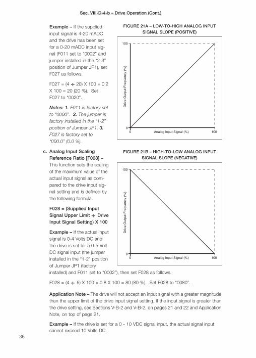
Sec. VIII-D-4-b – Drive Operation (Cont.)
Example – If the suppliedinput signal is 4-20 mADCand the drive has been setfor a 0-20 mADC input sig-nal (F011 set to “0002” andjumper installed in the “2-3”position of Jumper JP1), setF027 as follows.
F027 = (4 ÷ 20) X 100 = 0.2X 100 = 20 (20 %). SetF027 to “0020”.
Notes: 1. F011 is factory setto “0000”. 2. The jumper isfactory installed in the “1-2”position of Jumper JP1. 3.F027 is factory set to“000.0” (0.0 %).
c. Analog Input ScalingReference Ratio [F028] –This function sets the scalingof the maximum value of theactual input signal as com-pared to the drive input sig-nal setting and is defined bythe following formula.
F028 = (Supplied InputSignal Upper Limit ÷ DriveInput Signal Setting) X 100
Example – If the actual inputsignal is 0-4 Volts DC andthe drive is set for a 0-5 VoltDC signal input (the jumperinstalled in the “1-2” positionof Jumper JP1 (factoryinstalled) and F011 set to “0002”), then set F028 as follows.
F028 = (4 ÷ 5) X 100 = 0.8 X 100 = 80 (80 %). Set F028 to “0080”.
Application Note – The drive will not accept an input signal with a greater magnitudethan the upper limit of the drive input signal setting. If the input signal is greater thanthe drive setting, see Sections V-B-2 and V-B-2, on pages 21 and 22 and ApplicationNote, on top of page 21.
Example – If the drive is set for a 0 - 10 VDC signal input, the actual signal inputcannot exceed 10 Volts DC.
36
Driv
e O
utpu
t Fre
quen
cy (
%)
Analog Input Signal (%)00
100
100
FIGURE 21A – LOW-TO-HIGH ANALOG INPUTSIGNAL SLOPE (POSITIVE)
Driv
e O
utpu
t Fre
quen
cy (
%)
00
Analog Input Signal (%) 100
100
FIGURE 21B – HIGH-TO-LOW ANALOG INPUTSIGNAL SLOPE (NEGATIVE)

d. Analog Input Signal Slope [F029] – This function sets the slope of the input signal(Low-to-High / High-to-Low) to the output frequency, as shown in Figures 21A and21B on page 36.
Example – The drive is set for a 0 - 10 Volts DC input signal. However, the actualinput signal is 10 - 0 Volts DC. Use F029 to change the input signal slope from low-to-high to high-to-low.
5. Manual and Automatic Restart (F010, F016, F032, F035) – The drive can be pro-grammed for a manual restart (factory setting) or to automatically restart after a faulthas cleared, as described below. Also see Application Note (Auto Restart Delay [F034])in Section VIII-D-5-b, Note 3, on page 38.
WARNING! Do not set the drive for Automatic Restart unless you are sure itwill not cause injury or death in your application.
a. Manual Restart for “All Faults” Including AC Power Loss (Keypad Operation andExternal Run/Stop Contacts) – The drive has been factory programmed for a manu-al restart for “all faults” including a Short-Term AC power loss. See Tables 13A and13B. Also see “All Faults” Notes, on page 39.
Sec. VIII-D-4-c – Drive Operation (Cont.)
FunctionNumber
Function Description Code/Value Description of Code/Value
F010 Run/Stop-Forward/Reverse Control 0000* Keypad Operation
F032Automatic AC Line Start (for Short-Term**Power Loss)
0000* Disable Automatic AC Line Start
F035 Number of Auto Restart Attempts 0000* Zero Auto Restart Attempts
TABLE 13A – MANUAL RESTART FOR “ALL FAULTS” INCLUDINGAC POWER LOSS – KEYPAD OPERATION (FACTORY SETTING)
FunctionNumber
Function Description Code/Value Description of Code/Value
F010 Run/Stop-Forward/Reverse Control 0001 External Run/Stop Contacts
F016 Auto AC Line Start 0011Disable Auto AC Line Start whenExternal Run Command is On
F032Automatic AC Line Start (for Short-Term**Power Loss)
0000* Disable Automatic AC Line Start
F035 Number of Auto Restart Attempts 0000* Five Auto Restart Attempts
TABLE 13B – MANUAL RESTART FOR “ALL FAULTS” INCLUDINGAC POWER LOSS – EXTERNAL RUN/STOP CONTACTS
* Factory Setting. ** Short-Term Power Loss: Display is illuminated (“LU-C” is displayed). Long-Term Power Loss: Display is off.
* Factory Setting. ** Short-Term Power Loss: Display is illuminated (“LU-C” is displayed). Long-Term Power Loss: Display is off.
!
Note: To restart the drive after a short-term AC power loss (display illuminated“LU-C”), close and open the Reset contact or press the </RESET key. To elimi-nate the need to Reset the drive after a short-term power loss, set F032 = 0001[Enable Automatic AC Line Start] . To restart the drive after a long-term ACpower loss (display off), open and close the Run contact.
37

Sec. VIII-D-5 – Drive Operation (Cont.)
Notes: 1. When Function F016 is set to “0011”, the drive can be Reset for “Short-Term” Power Loss without having to open and close the Run contact.
WARNING! If Function F016 is left at factory setting (“0000”), the drivewill automatically restart due to a “long-term” power loss.
2. Auto Restart Delay [F034] – The drive can also be set to delay the AutomaticRestart (after a fault has cleared) for up to 800 seconds. This feature is useful forapplications where a certain amount of time should elapse (after a fault has cleared)before turning back on. Set F034 to the desired delay time, in Seconds (example:To set the Auto Restart Delay Time to 120 seconds, set F034 to “0120” (factorysetting is “0000”). This feature does not operate for Automatic AC Line Start.
c. Automatic Restart for All Faults Including AC Power Loss (with and withoutExternal Run/Stop Contacts) – If the application requires that the drive automaticallyrestart after a fault has cleared, including an AC power loss, set functions F010,F016, F032, and F035 as shown in Table 15, on page 39.
38
b. Automatic Restart for “All Faults” Except AC Power Loss (Keypad Operation andExternal Run/Stop Contacts) – The drive has been factory programmed for a manualrestart for “all faults” including a Short-Term** AC power loss. To program the drive forautomatic restart for “all faults” except AC power loss, see Tables 14A and 14B.
WARNING! Do not set the drive for Automatic Restart unless you are sureit will not cause injury or death in your application.
FunctionNumber
Function Description Code/Value Description of Code/Value
F010 Run/Stop-Forward/Reverse Control 0000* Keypad Operation
F032Automatic AC Line Start (for Short-Term**Power Loss)
0000* Disable Automatic AC Line Start
F035 Number of Auto Restart Attempts 0005 Five Auto Restart Attempts
TABLE 14A – AUTOMATIC RESTART FOR “ALL FAULTS” EXCEPTAC POWER LOSS – KEYPAD OPERATION
FunctionNumber
Function Description Code/Value Description of Code/Value
F010 Run/Stop-Forward/Reverse Control 0001 External Run/Stop Contacts
F016 Auto AC Line Start 0011Disable Auto AC Line Start whenExternal Run Command is On
F032Automatic AC Line Start (for Short-Term**Power Loss)
0000* Disable Automatic AC Line Start
F035 Number of Auto Restart Attempts 0005 Five Auto Restart Attempts
TABLE 14B – AUTOMATIC RESTART FOR “ALL FAULTS” EXCEPTAC POWER LOSS – EXTERNAL RUN/STOP CONTACTS
* Factory Setting. ** Short-Term Power Loss: Display is illuminated (“LU-C” is displayed). Long-Term Power Loss: Display is off.
* Factory Setting. ** Short-Term Power Loss: Display is illuminated (“LU-C” is displayed). Long-Term Power Loss: Display is off.
!
!
Sec. VIII-D-5-c – Drive Operation (Cont.)
“All Faults” Notes: 1. The faults that are automatically reset are indicated by thefollowing codes: OC-S, OC-A, OC-C, OC-d, OC-b, OU-C, LU-C, OH-C. 2. Thedrive must be manually restarted for an overcurrent fault (OL1, OL2, OL3) by press-ing the </RESET key or using an external reset. (See Table 22, on pages 74 and 75,for Fault Codes Description.)
Application Note: Normal Start Mode or Spin-Start Mode with High InertialLoads – In Normal Start Mode, when the AC line is reapplied (after the display turnsoff), the drive brakes the motor to zero speed and then accelerates (using F001) tothe set speed. In Spin-Start Mode, when the AC line is reapplied (after the displayturns off), the drive catches the spinning load and quickly accelerates it to the setspeed. The drive is factory set for Normal Start Mode (F048 is set to “0000”). Toset the drive for Spin-Start Mode, set F048 to “x1xx”. Note, in Manual RestartMode, if the drive is stopped and started with the Start/Stop Switch, the drive will“catch” the spinning load and accelerate (using F001) to the set speed, whether it isin Normal Start Mode or Spin-Start Mode.
6. Load Regulation and Torque Boost (F047, F072, F005, F075, F076, F070) – Thedrive contains two methods of stabilizing motor speed as a function of load. Betweenthe operating range of 15 Hz to 60 Hz, Slip Compensation is used to stabilize motorspeed. Below 15 Hz, Torque Boost is used. Depending on the load type, SlipCompensation and/or Torque Boost can be used.
a. Motor Current Display (F047) – In order to analyze proper motor operation, it isdesirable to set the drive to read motor current (Amps AC). This is accomplishedby setting Function F047 to “0100” [Enable Motor Current Display] as follows.Function F047 can be set with the drive in Run Mode or Stop Mode.
39
FunctionNumber
Function Description Code/Value Description of Code/Value
F010 Run/Stop-Forward/Reverse Control 0001 External Run/Stop Contacts
F016 Auto AC Line Start 0000*Enable Auto AC Line Start when ExternalRun Command is On
F032Automatic AC Line Start (for Short-Term***Power Loss)
0001 Enable Automatic AC Line Start
F035 Number of Auto Restart Attempts 0005 Five Auto Restart Attempts
TABLE 15 – AUTOMATIC RESTART FOR “ALL FAULTS” INCLUDINGAC POWER LOSS WITH OR WITHOUT** EXTERNAL RUN/STOP CONTACTS
* Factory Setting. ** For Automatic Restart without External Run/Stop Contacts, install a jumper between terminals “3”(FWD), and “5” (COM) of Terminal Block TM2. *** Short-Term Power Loss: Display is illuminated (“LU-C” is displayed).Long-Term Power Loss: Display is off.
Note: If external contacts for Run/Stop Operation are not required, the drivemust still be set for “external contacts” (F010 set to “0001”) and a jumpermust be installed between Terminals 3 and 5 of Terminal Block TM2.
WARNING! Do not set the drive for Automatic Restart unless you are sureit will not cause injury or death in your application.!

Sec. VIII-D-6-a – Drive Operation (Cont.)
To change the code setting of F047 from “0000” to “0100”:
1. Press the DSP/FUN key to display Function Number.
2. Press the </RESET key to move the setable digit one position to the left and the or key until “F047” is displayed. Note: The setable digit will flash.
3. Press the READ/ENTER key. The function setting will be displayed. Factory set-ting is “0000”.
4. Press the </RESET key two times to move to the second digit and press the key one time. “0100” will be displayed.
5. Press the READ/ENTER key to “enter” the new Display Mode. “End” will bemomentarily displayed, which confirms the new Display Mode setting. “F047”will be displayed.
6. Press the DSP/FUN key to return to the frequency display or press the or key to change to another function number.
7. Press the DSP/FUN key to toggle between Frequency, Function Number, andMotor Current.
b. Load Type (F072, F005) – Generally, motor loads can be categorized into threetypes: 1 - Constant Torque, 2 - Variable Torque, and 3 - Widely Changing Load.
1. Constant Torque Load (F072) – A load that does not vary substantially over thedrive’s speed range (example: conveyors, printing presses). The drive is factoryset to operate most constant torque loads over a 4:1 speed range (15 - 60 Hz).If a wider range of operation is required, Torque Boost must be set usingFunction F072. F072 can be set with the drive in Run Mode or Stop Mode.
To change the setting of F072 from “000.0” to “004.0” (4.0% is recommendedas an initial setting). Note: The 4% boost is in addition to the 7.5% boost estab-lished by the factory Volts/Hz curve.
a. Press the DSP/FUN key to display Function Number.
b. Press the </RESET key to move the setable digit one position to the left andthe or key until “F072” is displayed. Note: The setable digit will flash.
c. Press the READ/ENTER key. The function setting will be displayed. Factorysetting is “000.0”.
d. Press the </RESET key one time to move to the third digit. Note: The setabledigit will flash (00”0”.0).
e. Press the key four times. “004.0” is displayed .
f. Press the READ/ENTER key to “enter” the new Torque Boost. “End” will bemomentarily displayed, which confirms the new Torque Boost setting. “F072”will be displayed.
g. Press the DSP/FUN key to return to the frequency display or press the or key to change to another function number.40

Sec. VIII-D-6-b-1 – Drive Operation (Cont.)
Motor Current Procedure – After resetting Torque Boost, use the MotorCurrent Display to read motor current. Use the DSP/FUN key to toggle thedisplay between the last function number (F072), Frequency (Hz), and MotorCurrent (Amps AC). Note: When motor current is indicated on the display, the“AMP” LED on the keypad will illuminate.
To ensure the nameplate motor current is not exceeded, vary the drive fre-quency over the entire operating range while reading the Motor currentDisplay. This should be done at no load and full load. If the load currentexceeds the motor nameplate rating when above 15 Hz, the load may beexcessive due to improperly adjusted belts or defective bearings. If the loadcurrent exceeds the motor nameplate rating below 15 Hz, the boost mayneed to be adjusted above or below its initial setting.
2. Variable Torque Load (F005) – A load that increases as the speed of operationincreases (fans, blowers, centrifugal pumps). To set the drive for Variable TorqueLoads, use Function F005 [Volts/Hz Pattern] as follows. Set F005 to “0013” for60 Hz motors or to “0004” for 50 Hz motors. See Section IX, Function F005,on page 55.
To set the drive for a Variable Torque Load:
a. The drive must be in Stop Mode (press the RUN/STOP key).
b. Press the DSP/FUN key to display Function Number.
c. Press the </RESET key to move the setable digit one position to the left andthe or key until “F005” is displayed. Note: The setable digit will flash.
d. Press the READ/ENTER key. The function setting will be displayed. Factorysetting is “0009”.
e. Press a the </RESET key to move the setable digit one position to the leftand the or key until “0013” (for 60 Hz motors) or “0004” (for 50 Hzmotors) is displayed. Note: The setable digit will flash.
f. Press the READ/ENTER key to “enter” the setting for Variable Torque Loads(“0013” or “0004”). “End” will be momentarily displayed, which confirms theVariable Torque Load setting. “F005” will be displayed.
g. Press the DSP/FUN key to return to the frequency display or press the or key to change to another function number.
Note: To ensure the system is operating properly, the motor current should bemonitored over the entire speed range. See Motor Current Procedure above.
3. Widely Changing Load (F075, F076) – A load that can increase or decrease atany set speed (example: drill presses, positive displacement pumps, machinetools). In order for the drive to stabilize motor speed over a widely changingload, a combination of Slip Compensation and Torque Boost may have to beused. If the motor operating speed range is limited to 4:1 ratio (15 - 60 Hz) SlipCompensation must be used. 41
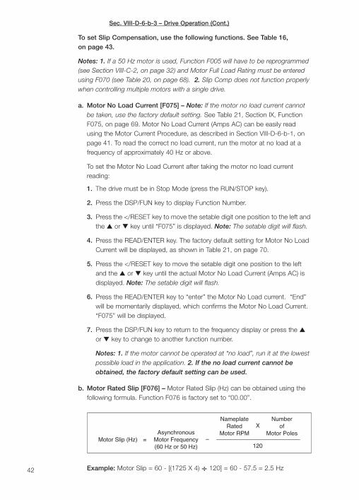
Sec. VIII-D-6-b-3 – Drive Operation (Cont.)
To set Slip Compensation, use the following functions. See Table 16,on page 43.
Notes: 1. If a 50 Hz motor is used, Function F005 will have to be reprogrammed(see Section VIII-C-2, on page 32) and Motor Full Load Rating must be enteredusing F070 (see Table 20, on page 68). 2. Slip Comp does not function properlywhen controlling multiple motors with a single drive.
a. Motor No Load Current [F075] – Note: If the motor no load current cannotbe taken, use the factory default setting. See Table 21, Section IX, FunctionF075, on page 69. Motor No Load Current (Amps AC) can be easily readusing the Motor Current Procedure, as described in Section VIII-D-6-b-1, onpage 41. To read the correct no load current, run the motor at no load at afrequency of approximately 40 Hz or above.
To set the Motor No Load Current after taking the motor no load currentreading:
1. The drive must be in Stop Mode (press the RUN/STOP key).
2. Press the DSP/FUN key to display Function Number.
3. Press the </RESET key to move the setable digit one position to the left andthe or key until “F075” is displayed. Note: The setable digit will flash.
4. Press the READ/ENTER key. The factory default setting for Motor No LoadCurrent will be displayed, as shown in Table 21, on page 70.
5. Press the </RESET key to move the setable digit one position to the leftand the or key until the actual Motor No Load Current (Amps AC) isdisplayed. Note: The setable digit will flash.
6. Press the READ/ENTER key to “enter” the Motor No Load current. “End”will be momentarily displayed, which confirms the Motor No Load Current.“F075” will be displayed.
7. Press the DSP/FUN key to return to the frequency display or press the or key to change to another function number.
Notes: 1. If the motor cannot be operated at “no load”, run it at the lowestpossible load in the application. 2. If the no load current cannot beobtained, the factory default setting can be used.
b. Motor Rated Slip [F076] – Motor Rated Slip (Hz) can be obtained using thefollowing formula. Function F076 is factory set to “00.00”.
Example: Motor Slip = 60 - [(1725 X 4) ÷ 120] = 60 - 57.5 = 2.5 Hz42
Asynchronous
(60 Hz or 50 Hz)Motor FrequencyMotor Slip (Hz) =
Number
Motor Poles
120–
Motor RPMRated
NameplateofX

Sec. VIII-D-6-b-3-b – Drive Operation (Cont.)
7. Display Modes [F047, F051, F052] – Sets the display to show various parameters.Figure 23, on page 44, shows the basic display of Motor Frequency and FunctionNumber. Press the DSP/FUN key repeatedly to toggle the display through MotorFrequency and Function Number.
43
To set the Motor Rated Slip:
1. Press the DSP/FUN key to display Function Number.
2. Press the </RESET key to move the setable digit one position to the left andthe or key until “F076” is displayed. Note: The setable digit will flash.
3. Press the READ/ENTER key. The factory default setting for Motor RatedSlip will be displayed. (“00.00”).
4. Press the </RESET key to move the setable digit one position to the leftand the or key until the desired Motor Rated Slip (Hz) is displayed.Note: The setable digit will flash.
5. Press the READ/ENTER key to “enter” the Motor Rated Slip. “End” will bemomentarily displayed, which confirms the Motor Rated Slip setting.“F076” will be displayed.
6. Press the DSP/FUN key to return to the frequency display or press the or key to change to another function number.
If the operating speed range is below 15 Hz, Torque Boost must also beused. See Section VIII-D-6-b-1 on page 40, for Torque Boost setting usingFunction F072. Be sure to follow the Motor Current Procedure, as describedin Section VIII-D-6-b-1, on page 41. The drive is now ready to control wide-ly changing loads over the operating speed range. See Table 16.
Notes: 1. Asynchronous Motor Frequency is 50 Hz or 60 Hz. 2. F076 canbe set with the drive in Run Mode or Stop Mode.
4. Special Motors – Although most motors are designed for 50 Hz and/or 60 Hzoperation at full output voltage of the drive, some motors operate at other fre-quencies. Figure 22, on page 44, illustrates how the drive can be set for a motorrated 400 Hz - 230 Volts AC. Section IX, Functions F037 through F041, onpages 60 and 61. Set F005 to “0018” [Custom Volts/Hz Pattern].
FunctionNumber
Description Setting
F070 Motor Current Enter motor nameplate current rating or use the factory default setting.
F071 Torque Boost “004.0” (factory setting is “0000”).
F075 Motor No Load Current Enter the actual motor no load current or use the factory default setting.
F076 Rated Slip See formula above.
F005 Volts/Hz Curve“0009” (factory Setting) for 60 Hz Motors.“0000” for 50 Hz Motors.
TABLE 16 – FUNCTIONS F070, F071, F075, F076, F005 SET FOR WIDELY CHANGING LOADS

Sec. VIII-D-7 – Drive Operation (Cont.)
a. Motor Voltage,Bus Voltage, andMotor CurrentDisplay Modes[F047] – AddsMotor Voltage, BusVoltage, and MotorCurrent to thebasic display.Function F047 isfactory set to“0000”, whichdisables the dis-plays. Figure 24,shows MotorVoltage, BusVoltage, and MotorCurrent added tothe basic display. Press the DSP/FUN key repeatedly to toggle the display throughDrive Output Frequency (or Motor RPM), Function Number, Motor Voltage, BusVoltage, and Motor Current. To enable all three parameters set F047 to “0111”. Therespective “status” indicator will illuminate when a specific parameter is displayed.See Section IX, F047, on page 63.
(F041=7.5) 17.3(F040=10.0) 23
(F039=40.0)
00 40 100
50
300
Motor Frequency (Hz)
200(F037=400.0)
400
Mot
or V
olta
ge (V
olts
AC)
100
150
(F038=100.0) 230
200
FIGURE 22 – CUSTOM VOLTS/HZ PATTERN FORA 400 Hz - 230 VOLT AC MOTOR
Power On
Press to
DSPFUN
Press to
FUNDSP
Function NumberChange Display Change Display
Line Voltage SettingFlashes 4 Times Display
Set FrequencyFlashes
Power On
Change DisplayPress toLine Voltage Setting
Flashes 4 TimesFunction Number
DSPFUN
Change DisplayPress to
DSPFUN
Display
Change DisplayChange DisplayDisplayMotor Voltage
DisplayBus Voltage
DisplayMotor CurrentPress to
FUNDSP
Press to
FUNDSP
the DrivePress To Run
STOPRUN
DisplaySet Frequency
DSP
Change DisplayPress to
FUN
Set FrequencyFlashes
FIGURE 23 – FLOW CHART FOR BASIC DISPLAY
FIGURE 24 – FLOW CHART SHOWING MOTOR VOLTAGE, BUS VOLTAGEAND MOTOR CURRENT ADDED TO THE BASIC DISPLAY
Note: The digital display will distinguuish between Motor Voltage and Bus Voltage bydisplaying a small “u” for Motor Voltage and a large “U” for Bus Voltage.
44

Sec. VIII-D-7-b – Drive Operation (Cont.)
8. Overtorque Control [F077, F078, F079] – In addition to Motor Overload Protection, thedrive can also provide overtorque indication or shut down in applications where the torque(or load) cannot be exceeded. Example: to prevent breakage in a film winding applicationif the load on the film increases beyond a preset point. Overtorque indication can be mon-itored using Terminals 10, 11 (Open Collector, F061 = "0005") or Terminals 1, 2 (OutputRelay, F098 = "0001"). The display will indicate "OL3" when the drive is in overtorque.
Function F077 is used to "enable" Overtorque Control and set the mode of operation.
Function F078 sets the Overtorque Threshold as a percent of full rated motor current.Example: if a motor is used in an application where the load cannot exceed 100 % offull rated torque, set F078 = "0100". 45
Change Display
Power On
Line Voltage SettingFlashes 4 Times Flashes
Set Motor RPMDisplay
Function NumberChange Display
Press to
FUNDSP
Press to
DSPFUN
Press To Runthe Drive
STOPRUN
DisplayMotor RPM
FIGURE 25 – FLOW CHART SHOWING THE BASIC DISPLAY CHANGED FROMDRIVE OUTPUT FREQUENCY TO MOTOR RPM
b. Drive output Frequency and Motor RPM [F051] – Changes the basic display fromDrive Output Frequency to Motor RPM. Function F051 is factory set to “0000”, to dis-play Drive Output Frequency. Figure 25 shows the basic display changed to MotorRPM and Function Number. To change the display to Motor RPM, set F051 to “0001”.(See Section IX, Function F051, on page 64.)
Notes: 1. The RPM display has been factory set for 4-pole motors using F036 =“0004”. For motors with other than 4-poles, set F036 to the actual number of motorpoles. 2. F051 is also used to set the decimal place for Function F052 [Line SpeedDisplay (Custom Units)].
c. Line Speed Display (Custom Units) [F052] – Changes the basic display from DriveOutput Frequency to Custom Units. F052 is factory set to “1800”, which representsmotor RPM at full output speed of the drive. Enter the significant digits of thedesired Custom Units value. This value is equal to the actual process output at theOutput Frequency Upper Limit setting of the drive (F006). Use Function F051 to setthe decimal place. Figure 26 shows the Custom Units set to 36.00. See Section IX,Functions F051 and F052, on page 64.
Example – To display 36.00 at full output frequency of the drive, set F052 to “3600”(four significant digits) and set F051 to “0004” (code represents two decimal places).
Change Display
Power On
Line Voltage SettingFlashes 4 Times (Custom Units)
Set Line Speed Function NumberDisplayChange Display
Press to
DSPFUN
Press to
DSPFUN
Flashes
Press To Runthe Drive
STOPRUN
Line Speed(Custom Units)
Display
FIGURE 26 – FLOW CHART SHOWING THE BASIC DISPLAY CHANGED FROMDRIVE OUTPUT FREQUENCY TO LINE SPEED (CUSTOM UNITS)

Sec. VIII-D-8 – Drive Operation (Cont.)
46
TABLE 17 – PROGRAMMABLE FUNCTIONS SUMMARY LIST
* Functions which can be changed while the drive is in Run Mode.
FunctionNumber
Function Description Function Range/CodeFactorySetting
PageNo.
UserSetting
F000 Drive Horsepower (Code) 0001 - 0040 (See Table 18, on page 53) — 53 —
F001* Acceleration Time # 1 (Seconds) 0.1 - 3600 010.0 53
F002* Deceleration Time # 1 (Seconds) 0.1 - 3600 010.0 54
F003External Forward-Stop-ReverseControl (F010 must be setto “0001”)
xx00: Forward/Stop-Reverse/Stop
xx01: Run/Stop-Forward/Reverse
xx10: 3-Wire Start/Stop Control
x0xx: Enable Reverse Command
x1xx: Disable Reverse Command
0xxx: When the Multifunction Input Terminals areProgrammed for Up/Down Frequency Control, the “SetFrequency” will Remain when the Drive is in “STOP”
1xxx: When the Multifunction Input Terminals areProgrammed for Up/Down Frequency Control, the “SetFrequency” will Revert to “Zero” when the Drive isin “STOP”
0000 54
F004 Parameter Lockout
xxx0: Enable F017 - F025xxx1: Disable F017 - F025xx0x: Enable All Functions Except F017 - F025xx1x: Disable All Functions Except F017 - F025
0000 54
F005 Volts/Hz Pattern
0000: Constant Torque - 50 Hz Motors
0004: Variable Torque (HVAC) - 50 Hz Motors
0009: Constant Torque - 60 Hz Motors
0013: Variable Torque (HVAC) - 60 Hz Motors
0018: Custom Volts/Hz Pattern See F037 - F041)
0009 55
F006 Output Frequency Upper Limit (Hz) 0.01 - 400.0 60.00 56
F007 Output Frequency Lower Limit (Hz) 0.00 - 400.0 0.00 56
F008Multifunction Open CollectorOutput - Frequency Reached (Hz)
0.00 - 400.0 0.00 56
F009 Bandwidth Setting (±) (Hz) 0.00 - 30.00 0.00 56
F010Run/Stop-Forward/ReverseControl
0000: Keypad Operation
0001: External Run/Stop Contacts (See F003)0000 56
F011 Frequency Control Method
0000: Keypad (See F025)
0001: Potentiometer on Keypad
0002: External Analog Signal Input or Remote Potentiometer0003: Up/Down Frequency Control Using Multifunction
Input Terminals 6, 7 (or 8)
0000 56
Function F079 sets the amount of time the load is allowed to stay in "overtorque"before the display indicates the overload condition ("OL3") and a programmed "over-torque" function activates.
E. Programmable Functions (Summary) – All functions have been factory set for mostapplications, as shown in Table 17. See Section IX, beginning on page 53, for a detaileddescription of each function.
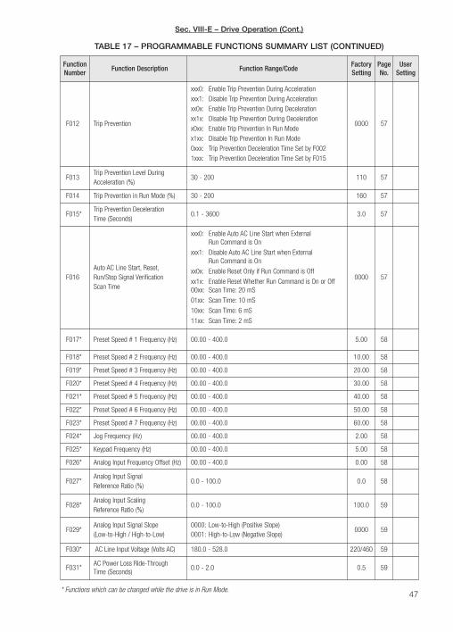
47
TABLE 17 – PROGRAMMABLE FUNCTIONS SUMMARY LIST (CONTINUED)
FunctionNumber
Function Description Function Range/CodeFactorySetting
PageNo.
UserSetting
F012 Trip Prevention
xxx0: Enable Trip Prevention During Accelerationxxx1: Disable Trip Prevention During Accelerationxx0x: Enable Trip Prevention During Decelerationxx1x: Disable Trip Prevention During Decelerationx0xx: Enable Trip Prevention In Run Modex1xx: Disable Trip Prevention In Run Mode0xxx: Trip Prevention Deceleration Time Set by F0021xxx: Trip Prevention Deceleration Time Set by F015
0000 57
F013Trip Prevention Level DuringAcceleration (%)
30 - 200 110 57
F014 Trip Prevention in Run Mode (%) 30 - 200 160 57
F015*Trip Prevention DecelerationTime (Seconds)
0.1 - 3600 3.0 57
F016Auto AC Line Start, Reset,Run/Stop Signal VerificationScan Time
xxx0: Enable Auto AC Line Start when ExternalRun Command is On
xxx1: Disable Auto AC Line Start when ExternalRun Command is On
xx0x: Enable Reset Only if Run Command is Off
xx1x: Enable Reset Whether Run Command is On or Off00xx: Scan Time: 20 mS
01xx: Scan Time: 10 mS
10xx: Scan Time: 6 mS
11xx: Scan Time: 2 mS
0000 57
F017* Preset Speed # 1 Frequency (Hz) 00.00 - 400.0 5.00 58
F018* Preset Speed # 2 Frequency (Hz) 00.00 - 400.0 10.00 58
F019* Preset Speed # 3 Frequency (Hz) 00.00 - 400.0 20.00 58
F020* Preset Speed # 4 Frequency (Hz) 00.00 - 400.0 30.00 58
F021* Preset Speed # 5 Frequency (Hz) 00.00 - 400.0 40.00 58
F022* Preset Speed # 6 Frequency (Hz) 00.00 - 400.0 50.00 58
F023* Preset Speed # 7 Frequency (Hz) 00.00 - 400.0 60.00 58
F024* Jog Frequency (Hz) 00.00 - 400.0 2.00 58
F025* Keypad Frequency (Hz) 00.00 - 400.0 5.00 58
F026* Analog Input Frequency Offset (Hz) 00.00 - 400.0 0.00 58
F027*Analog Input SignalReference Ratio (%)
0.0 - 100.0 0.0 58
F028*Analog Input ScalingReference Ratio (%)
0.0 - 100.0 100.0 59
F029*Analog Input Signal Slope(Low-to-High / High-to-Low)
0000: Low-to-High (Positive Slope)0001: High-to-Low (Negative Slope)
0000 59
F030* AC Line Input Voltage (Volts AC) 180.0 - 528.0 220/460 59
F031*AC Power Loss Ride-ThroughTime (Seconds)
0.0 - 2.0 0.5 59
* Functions which can be changed while the drive is in Run Mode.
Sec. VIII-E – Drive Operation (Cont.)

48
TABLE 17 – PROGRAMMABLE FUNCTIONS SUMMARY LIST (CONTINUED)
FunctionNumber
Function Description Function Range/CodeFactorySetting
PageNo.
UserSetting
F032Automatic AC Line Start (forShort-Term Power Loss)
0000: Disable Automatic AC Line Start0001: Enable Automatic AC Line Start
0000 59
F033*Analog Signal InputScan Time (mS X 2)
1 - 100 100 59
F034 Auto Restart Delay Time (Seconds) 0.0 - 800.0 0.0 59
F035 Number of Auto Restart Attempts 0 - 10 0 60
F036 Number of Motor Poles 2 - 72 4 60
F037Volts/Hz Pattern MaximumFrequency (Hz)
50.00 - 400.0 60.00 60
F038 Volts/Hz Pattern Voltage Ratio (%) 0.0 - 100.0 100.0 60
F039 Volts/Hz Pattern Mid Frequency (Hz) 0.11 - 400.0 3 60
F040Volts/Hz Pattern Mid VoltageRatio (%)
0 - 100.0 7.5 60
F041Volts/Hz Pattern Voltage Ratioat 0.1 Hz (%)
0 - 100.0 7.5 61
F042 Start Frequency (Hz) 0.10 - 10.00 1.00 61
F043 Switching Frequency (Code)
0000: 1.0 kHz 0006: 3.6 kHz 0012: 8.0 kHz0001: 1.2 kHz 0007: 4.0 kHz 0013: 9.0 kHz0002: 1.8 kHz 0008: 4.8 kHz 0014: 10 kHz0003: 2.0 kHz 0009: 5.0 kHz 0015: 12 kHz0004: 2.4 kHz 0010: 6.0 kHz0005: 3.0 kHz 0011: 7.2 kHz
0014 61
F044 Stop Method0000: Controlled Deceleration-to-Stop with DC Injection
Braking (Rapid Stop)0001: Coast-to-Stop
0000 61
F045* Analog Output Voltage Gain (%) 0 - 200 100 62
F046*Multifunction Analog OutputVoltage Mode (Terminals 14, 15)
0000: Output Frequency 0002: Drive Output Voltage0001: Set Frequency 0003: Bus Voltage
0000 63
F047* Display Mode (Volt., Curr.)
xxx0: Disable Motor Voltage Displayxxx1: Enable Motor Voltage Displayxx0x: Disable Bus Voltage Displayxx1x: Enable Bus Voltage Displayx0xx: Disable Motor Current Displayx1xx: Enable Motor Current Display
0000 63
F048Dynamic Brake, Stop Priority,Spin-Start, AutomaticVoltage Regulator
xxx0: Enhanced Brakingxxx1: Standard Brakingxx0x: Stop Key Enabled with External Contacts
(F010 = “0001”)xx1x: Stop Key Disabled with External Contacts
(F010 = “0001”)x0xx: Spin-Start Controlled by Multifunction Input Terminalsx1xx: Enable Spin-Start when the Drive is in Run Mode0xxx: Enable Automatic Voltage Regulator1xxx: Disable Automatic Voltage Regulator
0000 63
* Functions which can be changed while the drive is in Run Mode.
Sec. VIII-E – Drive Operation (Cont.)

49
TABLE 17 – PROGRAMMABLE FUNCTIONS SUMMARY LIST (CONTINUED)
FunctionNumber
Function Description Function Range/CodeFactorySetting
PageNo.
UserSetting
F049* Acceleration Time # 2 (Seconds) 0.1 - 3600 10.0 63
F050* Deceleration Time # 2 (Seconds) 0.1 - 3600 10.0 64
F051*Display Mode (Freq., RPM, LineSpeed Decimal Place)
0000: Drive Output Frequency is Displayed0001: Motor RPM is Displayed (see F036)0002: Line Speed Displayed in Whole Numbers (xxxx)0003: Line Speed Displayed with One Decimal Place (xxx.x)0004: Line Speed Displayed with Two Decimal Places (xx.xx)0005: Line Speed Displayed with Three Decimal Places (x.xxx)
0000 64
F052* Line Speed Display (Custom Units) 0 - 9999 1800 64
F053 DC Injection Brake Time (Seconds) 0.0 - 25.5 0.5 65
F054DC Injection Brake StartFrequency (Hz)
0.1 - 10.0 1.5 65
F055 DC Injection Brake Level (%) 0.0 - 20.0 8.0 65
F056Multifunction InputTerminal 6 (SP1)
Close Contact to Activate (NO)
0000: Preset Speed # 10001: Preset Speed # 20002: Preset Speed # 40003: Jog0004: Accel/Decel # 20005: Rapid Stop (E.S.)0006: Coast-to-Stop (b.b.)0007: Spin-Start0008: Energy Saving0009: Remote Signal Operation0010: Communication Selection 0011: Frequency Hold During Accel/Decel0012: Up Command0013: Down Command0014: Sequence Control0015: Master/Auxiliary Speed
Open Contact to Activate (NC)
0016: Preset Speed # 10017: Preset Speed # 20018: Preset Speed # 40019: Jog0020: Accel/Decel # 20021: Rapid Stop (E.S.)0022: Coast-to-Stop (b.b.)0023: Spin-Start0024: Energy Saving0025: Remote Signal Operation0026: Communication Selection0027: Frequency Hold During Accel/Decel0028: Up Command0029: Communication Section0030: Sequence Control0031: Master/Auxiliary Speed
0000 65
F057Multifunction InputTerminal 7 (SP2)
0001 66
F058Multifunction InputTerminal 8 (SP3)
0002 66
F059 Reserved — — 67
F060 Reserved — — 67
* Functions which can be changed while the drive is in Run Mode.
Sec. VIII-E – Drive Operation (Cont.)

50
TABLE 17 – PROGRAMMABLE FUNCTIONS SUMMARY LIST (CONTINUED)
FunctionNumber
Function Description Function Range/CodeFactorySetting
PageNo.
UserSetting
F061Multifunction Output Terminals10, 11 (Open Collector)
0000: Run0001: Frequency Reached (Target Frequency) (F008)0002: Set Frequency (F008 ± F009)0003: Frequency Greater than Target Frequency0004: Frequency Less than Target Frequency0005: Trip Due to Overload0006: Change 0000 (Run) from Normally Open
to Normally Closed
0000 67
F062 Reserved — — 67
F063 Reserved — — 67
F064 Reserved — — 67
F065 Skip Frequency # 1 (Hz) 0.00 - 400.0 0.00 67
F066 Skip Frequency # 2 (Hz) 0.00 - 400.0 0.00 67
F067 Skip Frequency # 3 (Hz) 0.00 - 400.0 0.00 67
F068 Skip Frequency Bandwidth (Hz) 0.00 - 10.0 0.00 67
F069Electronic Motor OverloadProtection Operation Mode
xxx0: Enable Electronic Motor Overload Protectionxxx1: Disable Electronic Motor Overload Protectionxx0x: Electronic Motor Overload Protection Set for
Non Inverter Duty Motorxx1x: Electronic Motor Overload Protection Set for
Inverter Duty Motorx0xx: Constant Torque (OL = 103%) (150% for 1minute)x1xx: Variable Torque (OL = 113%) (123% for 1minute)0xxx: Coast-to-Stop after Overload Protection is Activated1xxx: Drive will Not Trip when Overload Protection is
Activated (“OL1” will be Displayed)
0000 68
F070 Motor Rated Current (Amps AC) Enter the Motor Nameplate Rated Current Table 20 68
F071Drive Overload ProtectionEnable/Disable and TorqueBoost Mode
xxx0: Enable Drive Overload Protectionxxx1: Disable Drive Overload Protectionx0xx: Enable F072x1xx: Disable F072
0000 68
F072*Volts/Hz Curve Modification(Torque Boost) (%)
0.0 - 10.0 0.0 69
F073 Reserved — — 69
F074 Reserved — — 69
F075 Motor No Load Current (Amps AC) Enter the No Load Motor Current Table 21 69
F076* Motor Rated Slip (Hz) 0.00 - 6.00 0.00 69
F077 Overtorque Control
xxx0: Disable Overtorque Detectionxxx1: Enable Overtorque Detectionxx0x: Enable Overtorque Detection Only if at Set Frequencyxx1x: Enable Overtorque Detection while the Drive is
in Run Modex0xx: Drive will Continue to Operate After Overtorque
is Detectedx1xx: Coast-to-Stop After Overtorque is Detected
0000 70
* Functions which can be changed while the drive is in Run Mode.
Sec. VIII-E – Drive Operation (Cont.)

51
TABLE 17 – PROGRAMMABLE FUNCTIONS SUMMARY LIST (CONTINUED)
FunctionNumber
Function Description Function Range/CodeFactorySetting
PageNo.
UserSetting
F078 Overtorque Detection Level (%) 30 - 200 160 70
F079 Overtorque Detection Time (Sec.) 0.0 - 25.0 0.1 71
F080 Accel/Decel S-Curve Time # 1 (Sec.) 0.0 - 4.0 0.2 71
F081 Accel/Decel S-Curve Time # 2 (Sec.) 0.0 - 4.0 0.2 71
F082 Energy Saving Modexx00: Disable Energy Savingxx01: Energy Saving Controlled by Multifunction
Input Terminals0000 71
F083* Energy Saving Gain (%) 0 - 100 80 71
F084 Process Timer Operation Mode
xxx0: Disable Process Timerxxx1: Enable Process Timerxx0x: Set Frequency Output After Process Timer Completesxx1x: Zero Speed Output After Process Timer Completesx1xx: Automatically Repeat Process Timer Operation
0000 71
F085 Process Timer # 1 Time (Seconds) 0.0 - 3600 0.0 71
F086 Process Timer # 2 Time (Seconds) 0.0 - 3600 0.0 71
F087 Process Timer # 3 Time (Seconds) 0.0 - 3600 0.0 71
F088 Process Timer # 4 Time (Seconds) 0.0 - 3600 0.0 71
F089 Process Timer # 5 Time (Seconds) 0.0 - 3600 0.0 71
F090 Process Timer # 6 Time (Seconds) 0.0 - 3600 0.0 71
F091 Process Timer # 7 Time (Seconds) 0.0 - 3600 0.0 71
F092* Vibration Control Time (Seconds) 1 - 100 5 72
F093 Vibration Control Gain (%) 0.0 - 100 0 72
F094 Vibration Control Bias (%) 0 - 30 0 72
F095 Factory Setting — — 72
F096 Factory Setting — — 72
F097Multifunction Output Relay(Terminals 1, 2)
xxx0: Disabled in Auto Restart Modexxx1: Operational in Auto Restart Modexx0x: Disabled During Momentary Power Lossxx1x: Operational During Momentary Power Lossx0xx: Disabled in Rapid Stop modex1xx: Operational in Rapid Stop Mode0xxx: Disabled in Coast-to-Stop Mode1xxx: Operational in Coast-to-Stop Mode
0000 72
F098Multifunction Output Relay(Terminals 1, 2)
xxx0: Disabled when Overtorque Control is Activatedxxx1: Operational when Overtorque Control is Activatedxx0x: Disabled when Electronic Motor Overload
Protection is Activatedxx1x: Operational when Electronic Motor Overload
Protection is Activatedx0xx: Contacts are Normally Openx1xx: Contacts are Normally Closed0xxx: Disabled when Drive Overload Protection is Activated1xxx: Operational when Drive Overload Protection
is Activated
0000 72
* Functions which can be changed while the drive is in Run Mode.
Sec. VIII-E – Drive Operation (Cont.)

52
TABLE 17 – PROGRAMMABLE FUNCTIONS SUMMARY LIST (CONTINUED)
FunctionNumber
Function Description Function Range/CodeFactorySetting
PageNo.
UserSetting
F099 Reserved — — 73
F100Communication Identification Number
1 - 32 1 73
F101 Communication Baud Rate (bps)0000: 4800 0002: 19200
0001: 9600 0003: 384000001 73
F102 Communication Parameters
xxx0: 1 Stop Bit x0xx: Without Parity
xxx1: 2 Stop Bits x1xx: With Parity
xx0x: Even Parity 0xxx: 8-Bit Data
xx1x: Odd Parity 1xxx: 7-Bit Data
1100 73
F103 Factory Setting Only — — 73
F104 Factory Setting Only — — 73
F105 Factory Setting Only — — 73
F106 Factory Setting Only — — 73
F107 Reserved — — 73
F108 Reserved — — 73
F109 Reserved — — 73
F110 Reserved — — 73
F111 Reserved — — 73
F112 Reserved — — 73
F113 Reserved — — 73
F114 Reserved — — 73
F115 Reserved — — 73
F116 Reserved — — 73
F117 Reserved — — 73
F118 Reserved — — 73
F119 Reserved — — 73
F120 Reserved — — 73
F121 Reserved — — 73
F122 Reserved — — 73
F123 Reset Drive to Factory Settings1110: Reset for 50 Hz Motor Operation
1111: Reset for 60 Hz Motor Operation0000 73
F124 CPU Program Version — — 74
F125 Logs Last 3 Faults that Occurred See Table 22, on pages 74 - 76. — 74
* Functions which can be changed while the drive is in Run Mode.
Sec. VIII-E – Drive Operation (Cont.)

53
F001 ACCELERATION TIME #1
Factory Setting: 10.00 Seconds. F001 sets Acceleration Time # 1. The accelerationtime is the time it takes for the drive output to reach full speed as set in F006 [OutputFrequency Upper Limit]. The acceleration time is based on zero speed to full speed.
IX. PROGRAMMABLE FUNCTIONS (Detailed)The KBN2 Series drive contains user programmable functions which are described below.See Section VIII-A and VIII-B, on pages 27-31, for Digital Keypad Description and Operation.
Note: Function F123 is used to reset the drive to factory settings. Function F123,however, will not change the settings in Functions F000, F030, F100 - F122, and F124.
FUNCTION CODE REPRESENTATION
“x0xx” and “x1xx” indicate that only the “0” in “x0xx” and the “1” in “x1xx” is significant indescribing the function presented. The “x” is used for another function described under thesame function number.
F000 DRIVE HORSEPOWER CODE
Factory Setting: Set According to Model No. F000 is used to set the drive to thehorsepower of the motor used with the drive. See Table 18.
Model No. Part No.Drive Rating F000 Code
(Factory Setting)HP kW
KBN2-2250-1 12000 .50 .37 0001
KBN2-2201-1 12010 1 .75 0002
KBN2-2202-1 12020 2 1.5 0003
KBN2-2203-1 12030 3 2.2 0004
KBN2-2305-1 12040 5 3.7 0005
KBN2-2307-1 12050 7.5 5.6 0006
KBN2-2310-1 12060 10 7.5 0007
KBN2-2315-1 12070 15 11 0008
KBN2-2320-1 12080 20 15 0009
KBN2-2330-1 12090 30 22 0040
KBN2-4301-1 12100 1 .75 0010
KBN2-4302-1 12110 2 1.5 0011
KBN2-4303-1 12120 3 2.2 0012
KBN2-4305-1 12130 5 3.7 0013
KBN2-4307-1 12140 7.5 5.6 0014
KBN2-4310-1 12150 10 7.5 0015
KBN2-4315-1 12160 15 11 0016
KBN2-4320-1 12170 20 15 0017
KBN2-4330-1 12180 30 22 0018
TABLE 18 – DRIVE MODEL AND HORSEPOWER CODE SETTING
Sec. IX – Programmable Functions (Detailed)

Sec. IX – Programmable Functions (Detailed) (Cont.)
If the drive is set to less than full speed, the acceleration time will be proportionallyless. When accelerating high inertial loads, the acceleration time may be automaticallyextended due to the Trip Prevention Circuitry feature.
Programmable Range: 0.1 - 3600 Seconds
Note: A second acceleration time (Acceleration Time # 2) is available by using one ofthe Multifunction Input Terminals (“6”, “7”, or “8”). See Section IX, Function F049, onpage 63.
F002 DECELERATION TIME # 1
Factory Setting: 10.00 Seconds. F002 sets Deceleration Time # 1. The decelerationtime is the time it takes for the drive output setting to reach zero speed, as set in F007[Minimum Output Frequency], after a stop or zero speed command is given. The decel-eration time is based on full speed to zero speed.
If the drive is initially set to other than full speed, the deceleration time will be propor-tionally less. Also, when decelerating high inertial loads, the automatic regenerationprotection circuit may activate. This circuit will extend the deceleration time to preventthe drive from tripping, due to overcharging the bus capacitors.
Programmable Range: 0.1 - 3600 Seconds
Note: A second deceleration time (Deceleration Time # 2) is available by using one ofthe Multifunction Input Terminals (“6”, “7”, or “8”). See Section IX, Function F050, onpage 64.
F003 EXTERNAL FORWARD-STOP-REVERSE CONTROL
Factory Setting: 0000. F003 sets the drive for external forward/stop-reverse/stop orrun/stop-forward/reverse control. Set F010 [Start/Stop Control] to “0001”, for externalStart/Stop operation. See Section V-A, on page 18.
F003 = xx00: Forward/Stop-Reverse/Stopxx01: Run/Stop-Forward/Reversexx10: 3-Wire Start/Stop Controlx0xx: Enable Reverse Commandx1xx: Disable Reverse Command0xxx: When the Multifunction Input Terminals are Programmed for Up/Down
Frequency Control, the “Set Frequency” will Remain when the Drive is in “STOP”
1xxx: When the Multifunction Input Terminals are Programed for Up/DownFrequency Control, the Set Frequency will Revert to “Zero” when the Drive is in “STOP”
Notes: 1. If both the FWD and REV contacts are closed, the drive will be in StopMode. 2. If Reverse Operation does not function and “LOC” is displayed, change F003to “x0xx”.
F004 PARAMETER LOCKOUT
Factory Setting: 0000. F004 enables or disables (locks out) a set of functions.54
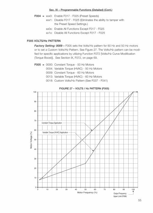
Sec. IX – Programmable Functions (Detailed) (Cont.)
55
F004 = xxx0: Enable F017 - F025 (Preset Speeds)xxx1: Disable F017 - F025 (Eliminates the ability to tamper with
the Preset Speed Settings.)
xx0x: Enable All Functions Except F017 - F025xx1x: Disable All Functions Except F017 - F025
F005 VOLTS/Hz PATTERN
Factory Setting: 0009 – F005 sets the Volts/Hz pattern for 60 Hz and 50 Hz motorsor to set a Custom Volts/Hz Pattern. See Figure 27. The Volts/Hz pattern can be modi-fied for specific applications by utilizing Function F072 [Volts/Hz Curve Modification(Torque Boost)]. See Section IX, F072, on page 69.
F005 = 0000: Constant Torque - 50 Hz Motors0004: Variable Torque (HVAC) - 50 Hz Motors0009: Constant Torque - 60 Hz Motors0013: Variable Torque (HVAC) - 60 Hz Motors0018: Custom Volts/Hz Pattern (See F037 - F041)
FIGURE 27 – VOLTS / Hz PATTERN (F005)
Mot
or V
olta
ge (
%)
0 10 20 30
20
10
0
30
40
50
60
70
80
Variable Torque (HVAC) Application
Constant Torque Application
90
100
40 50 60 70 80 90 100
Output FrequencyUpper Limit (F006)
Motor Frequency (%)
Sec. IX – Programmable Functions (Detailed) (Cont.)
F006 OUTPUT FREQUENCY UPPER LIMIT
Factory Setting: 60.00 Hz. F006 sets the Output Frequency Upper Limit (maximumoutput frequency) of the drive.
Programmable Range: 0.01 - 400 Hz
F007 OUTPUT FREQUENCY LOWER LIMIT
Factory Setting: 0.00 Hz. F007 sets the Output Frequency Lower Limit (minimum out-put frequency) of the drive.
Programmable Range: 0.00 - 400 Hz
F008 MULTIFUNCTION OPEN COLLECTOR OUTPUT FREQUENCY SETTING“Frequency Reached”
Factory Setting: 0.00 Hz. F008 sets the frequency at which the Multifunction OpenCollector Output (Terminals 10, 11) will change state when F061 is set to a specificoperation mode. See Section IX, Function F061, on page 67.
Programmable Range: 0.00 - 400.0 Hz
F009 BANDWIDTH SETTING
Factory Setting: 0.00 Hz. F009 sets the bandwidth of the operation of F008.
Programmable Range: 0.00 - 30.00 Hz
F010 START/STOP CONTROL
Factory Setting: 0000. F010 sets either Keypad Operation or External Start/StopControl
F010 = 0000: Keypad Operation0001: External Run/Stop Contacts (See F003)
Note: If F010 is set to “0001” [External Contacts], the Stop Function on the keypad(RUN/STOP key) remains operational.
F011 FREQUENCY CONTROL METHOD
Factory Setting: 0000. F011 sets the drive for either keypad control or external signalinput control (speed potentiometer, 0 - 5 VDC, 0 - 10 VDC, 0 - 20 mA DC, or 4 - 20mA DC).
F011 = 0000: Keypad0001: Potentiometer on Keypad0002: External Analog Signal Input or Remote Potentiometer0003: Up/Down Frequency Control Using Multifunction Input
Terminals 6, 7 (or 8)
Note: For Up/Down Frequency Control Using Multifunction Input Terminals “6”, “7” (or“8”), see Section V-B-4-a, on page 22.
56

Sec. IX – Programmable Functions (Detailed) (Cont.)
F012 TRIP PREVENTION
Factory Setting: 0000. F012 sets the condition at which the Trip Prevention will oper-ate. The drive contains Trip Prevention circuitry which will prevent tripping when driveoperation exceeds normal operating parameters.
F012 = xxx0: Enable Trip Prevention During Accelerationxxx1: Disable Trip Prevention During Accelerationxx0x: Enable Trip Prevention During Decelerationxx1x: Disable Trip Prevention During Decelerationx0xx: Enable Trip Prevention During Run Modex1xx: Disable Trip Prevention During Run Mode0xxx: Trip Prevention Deceleration Time Set by F002 (Deceleration Time #1)1xxx: Trip Prevention Deceleration Time Set by F015 (Trip Prevention
Deceleration Time)
F013 TRIP PREVENTION LEVEL DURING ACCELERATION
Factory Setting: 110 %. F013 sets the level at which the Trip Prevention is activatedwhile accelerating. In this mode, the actual acceleration time will increase if the setacceleration time is too short for the inertia of the load being accelerated.
Programmable Range: 30 - 200%
F014 TRIP PREVENTION LEVEL WHILE IN RUN MODE
Factory Setting: 160%. F014 sets the overcurrent level at which the Trip Prevention isactivated while in Run Mode. In this mode, the set output frequency will momentarilydecrease in order to attempt to reduce drive current due to transient overload. F012must be set to “x0xx” [Enable Trip Prevention While In Run Mode] (factory setting).
Programmable Range: 30 - 200 %
F015 TRIP PREVENTION DECELERATION TIME
Factory Setting: 3.0 Seconds. F015 sets an alternate deceleration time whenTrip Prevention is activated during the Run Mode (F014). Function F012 mustbe set to “1xxx”.
Programmable Range: 0.1 - 3600 Seconds
F016 AUTO AC LINE START, RESET, START/STOP SIGNAL VERIFICATION SCAN TIME
Factory Setting: 0000. Function F016 is used to control the AC line start and resetoperation modes. In addition, it is used to set the Start/Stop signal scan time.
Start/Stop-Forward/Reverse Terminals “3”, “4”, and “5” are scanned electronically inorder to verify the existence of a command. The scan time is factory set so that eachterminal is scanned every 20 mS. For shorter scan times, use Function F016.
57
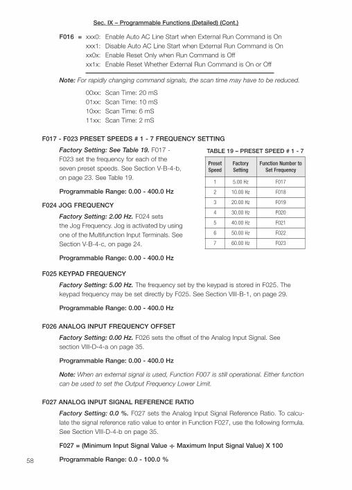
Sec. IX – Programmable Functions (Detailed) (Cont.)
F016 = xxx0: Enable Auto AC Line Start when External Run Command is Onxxx1: Disable Auto AC Line Start when External Run Command is Onxx0x: Enable Reset Only when Run Command is Offxx1x: Enable Reset Whether External Run Command is On or Off
Note: For rapidly changing command signals, the scan time may have to be reduced.
00xx: Scan Time: 20 mS01xx: Scan Time: 10 mS10xx: Scan Time: 6 mS11xx: Scan Time: 2 mS
F017 - F023 PRESET SPEEDS # 1 - 7 FREQUENCY SETTING
Factory Setting: See Table 19. F017 -F023 set the frequency for each of theseven preset speeds. See Section V-B-4-b,on page 23. See Table 19.
Programmable Range: 0.00 - 400.0 Hz
F024 JOG FREQUENCY
Factory Setting: 2.00 Hz. F024 setsthe Jog Frequency. Jog is activated by usingone of the Multifunction Input Terminals. SeeSection V-B-4-c, on page 24.
Programmable Range: 0.00 - 400.0 Hz
F025 KEYPAD FREQUENCY
Factory Setting: 5.00 Hz. The frequency set by the keypad is stored in F025. Thekeypad frequency may be set directly by F025. See Section VIII-B-1, on page 29.
Programmable Range: 0.00 - 400.0 Hz
F026 ANALOG INPUT FREQUENCY OFFSET
Factory Setting: 0.00 Hz. F026 sets the offset of the Analog Input Signal. Seesection VIII-D-4-a on page 35.
Programmable Range: 0.00 - 400.0 Hz
Note: When an external signal is used, Function F007 is still operational. Either functioncan be used to set the Output Frequency Lower Limit.
F027 ANALOG INPUT SIGNAL REFERENCE RATIO
Factory Setting: 0.0 %. F027 sets the Analog Input Signal Reference Ratio. To calcu-late the signal reference ratio value to enter in Function F027, use the following formula.See Section VIII-D-4-b on page 35.
F027 = (Minimum Input Signal Value ÷ Maximum Input Signal Value) X 100
Programmable Range: 0.0 - 100.0 %58
PresetSpeed
FactorySetting
Function Number toSet Frequency
1 5.00 Hz F017
2 10.00 Hz F018
3 20.00 Hz F019
4 30.00 Hz F020
5 40.00 Hz F021
6 50.00 Hz F022
7 60.00 Hz F023
TABLE 19 – PRESET SPEED # 1 - 7

Sec. IX – Programmable Functions (Detailed) (Cont.)
F028 ANALOG INPUT SCALING REFERENCE RATIO
Factory Setting: 100.0 %. F028 sets the Analog Input Signal Scaling Reference Ratio.F028 is factory set to “100.0”, which will provide 100% scaling of the ratio of the ana-log input signal to the drive signal input setting. See Section VIII-D-4-c on page 36.
Programmable Range: 0.00 - 100.0 %
F029 ANALOG INPUT SIGNAL SLOPE (Low-to-High / High-to-Low)
Factory Setting: 0000. F029 sets the drive to run the motor with a low-to-high orhigh-to-low signal input. See Section VIII-D-4-d, on page 37.
F029 = 0000: Low-to-High (Positive Slope)0001: High-to-Low (Negative Slope)
F030 AC LINE INPUT VOLTAGE
Factory Setting: 220.0 Volts AC (208/230 VAC Models) and 460.0 Volts AC (308/460VAC Models). F030 sets the drive for the actual AC line input voltage being applied.
Programmable Range: 180.0 - 528.0 Volts AC
F031 AC POWER LOSS RIDE-THROUGH TIME
Factory Setting: 0.5 Seconds. F031 sets the amount of time of AC power lossallowed before the drive trips.
Programmable Range: 0.0 - 2.0 Seconds
F032 AUTOMATIC AC LINE START
Factory Setting: 0000. When F032 is used in conjunction with other functions, the drivecan be set for Automatic Restart with the AC line. See Section VIII-5-c, on page 38.
F032 = 0000: Disable Automatic AC Line Start0001: Enable Automatic AC Line Start
F033 ANALOG SIGNAL INPUT SCAN TIME
Factory Setting: 100 (200 mS) F033 sets the amount of time that Terminal 13 will bescanned for presence of a signal (in 2 mS increments). This is the minimum amount oftime that the drive requires for the signal to be present. If the signal is not present dur-ing the time specified, the drive will treat the signal as “zero” and will not respond.
Programmable Range: 1 - 100 (mS x 2)
Note: Reduced scan time will eliminate noise on slow charging input signals.
F034 AUTO RESTART DELAY TIME
Factory Setting: 0.00 Seconds. F034 sets the time between automaticrestart attempts for all faults except Automatic AC Line Start.
Programmable Range: 0.0 - 800.0 Seconds59
Sec. IX – Programmable Functions (Detailed) (Cont.)
WARNING! Use caution when setting restart delay times, since machinery mayrestart unexpectedly.
F035 NUMBER OF AUTO RESTART ATTEMPTS
Factory Setting: 0 Auto Restart Attempts. F035 sets the number of Auto RestartAttempts that will be performed after a fault has cleared. If the number of restart attemptsexceeds the setting in Function F035, the drive will need to be manually restarted.
Programmable Range: 0 - 10 Auto Restart Attempts
F036 NUMBER OF MOTOR POLES
Factory Setting: 4 Poles. F036 sets the number of motor poles. This function isrequired when the drive is programmed to display Motor RPM using Function F051(F051 = “0001”). If the number of motor poles is not known, use the following formula:
Number of Motor Poles =(Motor Nameplate Rated Frequency X 120) ÷ Motor Rated RPM
Example – If using a 60 Hz, 1725 RPM motor, calculate the number of motorpoles as follows.
F036 = (60 X 120) ÷ 1725 = 7200 ÷ 1725 = 4.17. Set F036 to “0004” (4 motor poles).
Programmable Range: 2 - 72 Poles
F037 VOLTS/Hz PATTERN MAXIMUM FREQUENCY
Factory Setting: 60.00 Hz. F037 sets the Volts/Hz Pattern Maximum Frequency whenusing a custom Volts/Hz pattern (F005 = “0018”). See Figure 22, on page 44.
Programmable Range: 50.00 - 400.0 Hz
F038 VOLTS/Hz PATTERN VOLTAGE RATIO
Factory Setting: 100.0 %. F038 sets the Volts/Hz Pattern Voltage Ratio when using acustom Volts/Hz pattern (F005 = “0018”). See Figure 22, on page 44.
Programmable Range: 0.00 - 100.0 %
F039 VOLTS/Hz PATTERN MID FREQUENCY
Factory Setting: 3.00 Hz. F039 sets the Volts/Hz Pattern Mid Frequency when using acustom Volts/Hz pattern (F005 = “0018”). See Figure 22, on page 44.
Programmable Range: 0.11 - 400.0 Hz
F040 VOLTS/Hz PATTERN MID VOLTAGE RATIO
Factory Setting: 7.5%. F040 sets the Volts/Hz Pattern Mid Voltage Ratio when usinga custom Volts/Hz pattern (F005 = “0018”). See Figure 22, on page 44.
Programmable Range: 0.0 - 100.0%
60
!

Sec. IX – Programmable Functions (Detailed) (Cont.)
F041 VOLTS/Hz PATTERN VOLTAGE RATIO AT 0.1 Hz
Factory Setting: 7.5%. F041 sets the Volts/Hz Pattern Voltage Ratio at 0.1 Hz whenusing a custom volts/Hz pattern (F005 = “0018”). See Figure 22, on page 44.
Programmable Range: 0.0 - 100.0 %
F042 START FREQUENCY
Factory Setting: 1.00 Hz. F042 sets the minimum Start Frequency of the drive.Although the drive will start at the frequency set by F042, it will still have a controlledrange down to 0.1 Hz.
Programmable Range: 0.10 - 10.00 Hz
F043 SWITCHING FREQUENCY (Code)
Factory Setting: 0014. F043 sets the Switching Frequency (Code). F043 is factory setto “0014”, which operates the drive at 10 kHz and provides low motor noise and goodmotor torque. Increasing the switching frequency to the maximum of 12 kHz will furtherreduce motor noise. However, increased radio frequency interference will result as wellas 10% derating of the maximum output current. Reducing the switching frequency willprovide increased motor torque. However, the audible noise will also increase.
F043 = 0000: 1.0 kHz 0004: 2.4 kHz 0008: 4.8 kHz 0012: 8.0 kHz0001: 1.2 kHz 0005: 3.0 kHz 0009: 5.0 kHz 0013: 9.0 kHz0002: 1.8 kHz 0006: 3.6 kHz 0010: 6.0 kHz 0014: 10 kHz0003: 2.0 kHz 0007: 4.0 kHz 0011: 7.2 kHz 0014: 12 kHz
F044 STOP METHOD
Factory Setting: 0000. F044 sets either controlled deceleration-to-stop or coast-to-stop when a stop command is given. The controlled deceleration function uses a com-bination of regeneration and DC injection braking to stop the motor. The factory settingutilizes regeneration as the primary method of braking. When the Stop Command isgiven, the motor will decelerate in accordance to the deceleration time set by F002[Deceleration Time # 1]. When the output frequency reaches 1.5 Hz, the injectionbraking begins to take effect. For high inertial loads, the optional Brake Resistor maybe required (available for models through 10 HP). See Figure 28, on page 62 andSection IX, Functions F053, F054, and F055, on page 65.
F044 = 0000: Controlled Deceleration-to-Stop with DC Injection Braking (Rapid Stop)0001: Coast-to-Stop
Application Note – Controlled Deceleration-to-Stop with Injection Braking (Rapid Stop)can also be activated with a Multifunction Input Terminal set to code “0005”. Coast-to-Stop can also be activated with a Multifunction Input Terminal set to code “0006”. Ifthe drive is stopped, as per above, it must be restarted with the RUN/STOP key, if thedrive is set to Keypad Control, or it must be restarted by opening and closing the Runcontact, if the drive is set for External Start/Stop Contacts.
61
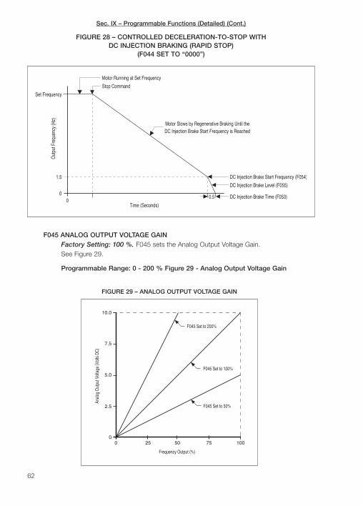
Sec. IX – Programmable Functions (Detailed) (Cont.)
62
F045 ANALOG OUTPUT VOLTAGE GAINFactory Setting: 100 %. F045 sets the Analog Output Voltage Gain.See Figure 29.
Programmable Range: 0 - 200 % Figure 29 - Analog Output Voltage Gain
DC Injection Brake Start Frequency is ReachedMotor Slows by Regenerative Braking Until the
00
1.5
Time (Seconds)
Out
put F
requ
ency
(Hz)
Stop Command
Motor Running at Set Frequency
DC Injection Brake Start Frequency (F054)
DC Injection Brake Level (F055)
DC Injection Brake Time (F053)0.5
Set Frequency
FIGURE 28 – CONTROLLED DECELERATION-TO-STOP WITHDC INJECTION BRAKING (RAPID STOP)
(F044 SET TO “0000”)
00
Frequency Output (%)
10050
Anal
og O
utpu
t Vol
tage
(Vol
ts D
C)
10.0
5.0
7.5
2.5
F045 Set to 100%
F045 Set to 200%
F045 Set to 50%
25 75
FIGURE 29 – ANALOG OUTPUT VOLTAGE GAIN
Sec. IX – Programmable Functions (Detailed) (Cont.)
F046 MULTIFUNCTION ANALOG OUTPUT VOLTAGE MODE
Factory Setting: 0000 – F046 sets the operation of the Multifunction Analog OutputVoltage (Terminals 14, 15). Provides a linear DC output voltage (0 - 10 Volts DC) pro-portional to the mode setting.
F046 = 0000: Output Frequency 0002: Drive Output Voltage0001: Set Frequency 0003: Bus Voltage
F047 DISPLAY MODE (Volt., Curr.)
Factory Setting: 0000 – F047 sets the Display Mode. The display is factory pro-grammed to show Drive Output Frequency (see F051). The respective “status” indica-tor will illuminate when the specific parameter is displayed.
F047 = xxx0: Disable Motor Voltage Displayxxx1: Enable Motor Voltage Displayxx0x: Disable Bus Voltage Displayxx1x: Enable Bus Voltage Displayx0xx: Disable Motor Current Displayx1xx: Enable Motor Current Display
Notes: 1. The drive is factory programmed to alternately display Drive Output Frequencyand Function Number when the DSP/FUN key is pressed. If F047 is set to “0111”, press-ing the DSP/FUN key repeatedly will toggle the display to show Motor Set Frequency(Hz), Function Number, Motor Voltage (Volts AC), Bus Voltage (Volts DC), and MotorCurrent (Amps AC). 2. The digital display will distinguish between Motor Voltage and BusVoltage by displaying a small “u” for Motor Voltage and a large “U” for Bus Voltage.
F048 DYNAMIC BRAKE, STOP PRIORITY, SPIN-START, AUTOMATIC VOLTAGE REGULATOR
Factory Setting: 0000 – F048 sets the Dynamic Brake, Stop Priority, Spin-Start, andAutomatic Voltage Regulator.
F048 = xxx0: Enhanced Brakingxxx1: Standard Brakingxx0x: Enable STOP key with External Contacts (F010 = 0001)xx1x: Disable STOP key is with External Contacts (F010 = 0001)x0xx: Spin-Start Controlled by Multifunction Input Terminalsx1xx: Enable Spin-Start when the Drive is in Run Mode0xxx: Enable Automatic Voltage Regulator1xxx: Disable Automatic Voltage Regulator
F049 ACCELERATION TIME # 2
Factory Setting: 10.00 Seconds – F049 sets Acceleration Time # 2. The accelerationtime is the time it takes for the drive output to reach full speed as set in F006 [OutputFrequency Upper Limit]. The acceleration time is based on zero speed to full speed.Acceleration Time # 2 is activated by programming one of the three multifunction inputterminals “6”, “7”, or “8” to “0004” (or “0020”) using F056, F057, or F058.
63
Sec. IX – Programmable Functions (Detailed) (Cont.)
If the drive is set to less than full speed, the acceleration time will be proportionallydecreased. In order to prevent an overcurrent trip, when accelerating high inertialloads, the acceleration time may be automatically extended and the current limit circuitmay activate.
Programmable Range: 0.1 - 3600 Seconds
F050 DECELERATION TIME # 2
Factory Setting: 10.00 Seconds. F050 sets Deceleration Time # 2. The decelerationtime is the time it takes for the drive output setting to reach zero speed, as set in F007[Minimum Output Frequency], after a stop or zero speed command is given. The decel-eration time is based on full speed to zero speed. Deceleration Time # 2 is activated byprogramming one of the three multifunction input terminals “6”, “7”, or “8” to “0004” (or“0020”) using F056, F057, or F058.
If the drive is initially set to other than full speed, the deceleration time will be propor-tionally less. Also, when decelerating high inertial loads, the automatic regenerationprotection circuit may activate. This circuit will extend the deceleration time to preventthe drive from tripping, due to overcharging the bus capacitors.
Programmable Range: 0.1 - 3600 Seconds
F051 DISPLAY MODE (FREQ., RPM, LINE SPEED DECIMAL PLACE)
Factory Setting: 0000. F051 sets the Digital Display Mode.
F051 = 0000: Drive Output Frequency is Displayed0001: Motor RPM is Displayed (See F036)0002: Line Speed Displayed in Whole Numbers (xxxx)0003: Line Speed Displayed with One Decimal Place (xxx.x)0004: Line Speed Displayed with Two Decimal Places (xx.xx)0005: Line Speed Displayed with Three Decimal Places (x.xxx)
Notes: 1. When F051 is set to “0001” the display will indicate motor RPM instead ofDrive Output Frequency. F036 must be set to the correct number of motor poles forthe RPM readout to be correct. 2. When F051 is set to “0002” - “0005”, line speed willbe displayed instead of Drive Output Frequency or RPM.
F052 LINE SPEED DISPLAY (CUSTOM UNITS)
Factory Setting: 1800. F052 sets Line Speed or Custom Units for a specific processoutput. Enter the significant digits in F052 and use F051 to set the decimal place.
Example – If a conveyor operates at 36 ft/min at full speed (set by F006) and thereadout is desired with 2 decimal places, enter “3600” in F052 and “0004” in F051.Readout at full speed will be “36.00”.
Programmable Range: 0 - 9999
64
Sec. IX – Programmable Functions (Detailed) (Cont.)
F053 DC INJECTION BRAKE TIME
Factory Setting: 0.5 Seconds. F053 sets the DC Injection Brake Time. The braketime should not exceed the actual time to stop the load since it may cause overheatingof the motor. See Figure 28, on page 62.
Programmable Range: 0 - 25.5 Seconds
F054 DC INJECTION BRAKE START FREQUENCY
Factory Setting: 1.5 Hz. F054 sets the frequency at which the DC injection brakebegins. See Figure 28, on page 62.
Programmable Range: 1 - 10 Hz
F055 DC INJECTION BRAKE LEVEL
Factory Setting: 8.0 %. F17 sets the DC injection brake level, as a percent of busvoltage. See Figure 28, on page 62.
Programmable Range: 0 - 20%
Note: Do not increase the DC Injection Brake Level beyond what is necessary to stopthe motor since motor overheating may occur.
F056 MULTIFUNCTION INPUT TERMINAL “6” (SP1)
Factory Setting: 0000. F056 sets the operation of Terminal 6 of Terminal Block TM2.See Notes – Multifunction Input Terminal Codes, on page 66.
Close Contact to Activate Open Contact to Activate(Norm. Open) (Norm. Closed)
F056 = 0000: Preset Speed # 11 0016: Preset Speed # 11
0001: Preset Speed # 21 0017: Preset Speed # 21
0002: Preset Speed # 41 0018: Preset Speed # 41
0003: Jog 2 0019: Jog 2
0004: Accel/Decel # 23 0020: Accel/Decel # 23
0005: Rapid Stop (E.S.) 4,5 0021: Rapid Stop (E.S.) 4,5
0006: Coast-to-Stop (b.b.) 5 0022: Coast-to-Stop (b.b.)5
0007: Spin-Start 6 0023: Spin-Start 6
0008: Energy Saving 7 0024: Energy Saving 7
0009: Remote Signal Operation8 0025: Remote Signal Operation 8
0010: Communication Selection 9 0026: Communication Selection9
0011: Frequency Hold During 0027: Frequency Hold DuringAccel/Decel10 Accel/Decel10
0012: Up Command11 0028: Up Command11
0013: Down Command11 0029: Down Command11
0014: Sequence Control12 0030: Sequence Control12
0015: Master/Auxiliary Speed13 0031: Master/Auxiliary Speed13
65
Sec. IX – Programmable Functions (Detailed) (Cont.)
F057 MULTIFUNCTION INPUT TERMINAL “7” (SP2)
Factory Setting: 0001. F057 sets the operation of Terminal 7 of Terminal Block TM2.
Close Contact to Activate (Norm. Open*)
F057 = 0000: Preset Speed # 1 1 0008: Energy Saving 7
0001: Preset Speed # 2 1 0009: Remote Signal Operation8
0002: Preset Speed # 4 1 0010: Communication Selection9
0003: Jog 2 0011: Frequency Hold DuringAccel/Decel10
0004: Accel/Decel # 23 0012: Up Command11
0005: Rapid Stop (E.S.) 4, 5 0013: Down Command11
0006: Coast-to-Stop (b.b.) 5 0014: Sequence Control12
0007: Spin-Start 6 0015: Master/Auxiliary Speed13
F058 MULTIFUNCTION INPUT TERMINAL “8” (SP3)
Factory Setting: 0002. F058 sets the operation of Terminal 8 of Terminal Block TM2.
Close Contact to Activate (Norm. Open*)
F058 = 0000: Preset Speed # 1 1 0008: Energy Saving 7
0001: Preset Speed # 2 1 0009: Remote Signal Operation8
0002: Preset Speed # 4 1 0010: Communication Selection9
0003: Jog 2 0011: Frequency Hold DuringAccel/Decel10
0004: Accel/Decel # 23 0012: Up Command11
0005: Rapid Stop (E.S.) 4, 5 0013: Down Command11
0006: Coast-to-Stop (b.b.) 5 0014: Sequence Control12
0007: Spin-Start 6 0015: Master/Auxiliary Speed13
*For Norm. Closed contacts use Function Codes “0016” - ”0031”. See F056 on page 65.
Notes - Multifunction Input Terminal Codes (Refer to the Following for Additional Information):
1. Section V-B-4-b, Preset Speed Operation, on page 23. 2. Section V-B-4-c, Jog SpeedOperation, on page 24. 3. Functions F049 and F050, Accel/Decel Time # 2, on pages 49and 50. 4. The drive will stop by using Regenerative and Injection Braking. See FunctionF044, Stop Method, on page 61, and Figure 28, on page 62. Also see related FunctionsF053 - F055, DC Injection Brake, on pages 64 and 65. 5. To restart the drive, open andclose the Run Contacts. If Start/Stop is set for Keypad Operation (F010 = 0000), press theRUN/STOP key to restart the drive. 6. Section VIII-D-5-c, Spin-Start Application Note, onpage 39. 7. Functions F082 and F083, Energy Saving, on page 71. 8. Drive operation willchange from Keypad Control to External Start/Stop (Terminals "3", "4", and "5", of TerminalBlock TM2 ) and External Frequency Control (Terminals "13" and "14", of Terminal BlockTM2). 9. Disables operation by communications except for reading of drive function settingsand operational status. 10. The drive ceases to accelerate or decelerate and will remain at"hold" frequency. 11. Section V-B-4-a, External Up/Down Frequency Control, on page 22.12. Section V-B-4-b, Preset Speed Operation and Notes 1-5, Sequence Control, on page23. Also see Function 84, Process Timer Operation Mode, on page 71. 13. Exchanges fre-quency command between the keypad potentiometer and external signals (or remote poten-tiometer) on Terminals "12" and "14", of Terminal Block TM2.
66
Sec. IX – Programmable Functions (Detailed) (Cont.)
F059 & F060 ARE RESERVED
F061 MULTIFUNCTION OUTPUT TERMINALS 10, 11 (Open Collector)
Factory Setting: 0000 – F061 sets the operation of Multifunction Output Terminals 10and 11, which will change state when the drive operates as programmed in F061.F061 is factory set to “0000” [Run], which will make the Multifunction Open CollectorOutput Terminal change state when the drive is in the Run Mode.
F061 = 0000: Run0001: Frequency Reached (Target Frequency) (F008)0002: Set Frequency (F008 ± F009)0003: Frequency Greater than Target Frequency0004: Frequency Less than Target Frequency0005: Trip Due to Overload0006: Change 0000 (Run) from Normally Open to Normally Closed
Notes: 1. If the open collector output is used with a relay, a clamping diode must beused, as shown in Figure 14, on page 24. 2. The Frequency Reached (Target Frequency)is set by Function F008.
F062, F063 & F064 ARE RESERVED
F065 SKIP FREQUENCY # 1
Factory Setting: 0.00 Hz – F065 sets Skip Frequency # 1.
Programmable Range: 0.00 - 400.0 Hz
Note: Skip frequencies are used to eliminate mechanical vibration or resonanceat certain speeds.
F066 SKIP FREQUENCY # 2
Factory Setting: 0.00 Hz. F066 sets Skip Frequency # 2.
Programmable Range: 0.00 - 400.0 Hz
F067 SKIP FREQUENCY # 3
Factory Setting: 0.00 Hz. F067 sets Skip Frequency # 3.
Programmable Range: 0.00 - 400.0 Hz
F068 SKIP FREQUENCY BANDWIDTH
Factory Setting: 0.00 Hz. F068 sets the Skip Frequency Bandwidth.
Programmable Range: 0.00 - 10.00 Hz
Example – If F065 is set to 10.00 Hz, F066 is set to 20.00 Hz, F067 is set to 30.00Hz, and F068 is set to 2.00 Hz, the frequencies that will be skipped are 8 - 12 Hz,18 - 22 Hz, and 28 - 32 Hz.
67
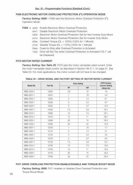
F071 DRIVE OVERLOAD PROTECTION ENABLE/DISABLE AND TORQUE BOOST MODE
Factory Setting: 0000. F071 enables or disables Drive Overload Protection andTorque Boost Mode.
Sec. IX – Programmable Functions (Detailed) (Cont.)
68
F069 ELECTRONIC MOTOR OVERLOAD PROTECTION (I2t) OPERATION MODE
Factory Setting: 0000 – F069 sets the Electronic Motor Overload Protection (I2t)Operation Mode.
F069 = xxx0: Enable Electronic Motor Overload Protectionxxx1: Disable Electronic Motor Overload Protectionxx0x: Electronic Motor Overload Protection Set for Non Inverter Duty Motorxx1x: Electronic Motor Overload Protection Set for Inverter Duty Motorx0xx: Constant Torque (OL = 103%) (150% for 1 Minute)x1xx: Variable Torque (OL = 113%) (123% for 1 Minute)0xxx: Coast-to-Stop after Overload Protection is Activated1xxx: Drive will Not Trip when Overload Protection is Activated (“OL1” will
be Displayed)
F070 MOTOR RATED CURRENT
Factory Setting: See Table 20. F070 sets the motor nameplate rated current. Enterthe motor nameplate rated current, as described in Section VIII-C-1, on page 31. SeeTable 20. For most applications, the motor current will not have to be changed.
Model No. Part No.Drive Rating F070 Factory
Current Setting(Amps Ac)HP kW
KBN2-2250-1 12000 .50 .37 1.9
KBN2-2201-1 12010 1 .75 3.4
KBN2-2202-1 12020 2 1.5 6.1
KBN2-2203-1 12030 3 2.2 8.7
KBN2-2305-1 12040 5 3.7 13.5
KBN2-2307-1 12050 7.5 5.6 20.1
KBN2-2310-1 12060 10 7.5 25.1
KBN2-2315-1 12070 15 11 36.7
KBN2-2320-1 12080 20 15 50.3
KBN2-2330-1 12090 30 22 72.9
KBN2-4301-1 12100 1 .75 1.7
KBN2-4302-1 12110 2 1.5 3.1
KBN2-4303-1 12120 3 2.2 4.4
KBN2-4305-1 12130 5 3.7 6.8
KBN2-4307-1 12140 7.5 5.6 10.1
KBN2-4310-1 12150 10 7.5 12.6
KBN2-4315-1 12160 15 11 18.4
KBN2-4320-1 12170 20 15 25.2
KBN2-4330-1 12180 30 22 36.5
TABLE 20 – DRIVE MODEL AND FACTORY SETTING OF MOTOR RATED CURRENT

F073 & F074 ARE RESERVED
F075 MOTOR NO LOAD CURRENT
Factory Setting: See Table 21, on page 70 . F075 sets the no load motor currentwhich is used for Slip Compensation. Enter the no load motor current, as described inSection VIII-D-6-b-3-a, on page 34.
F076 MOTOR RATED SLIP
Factory Setting: 0.00 Hz. F076 sets the Motor Rated Slip. This function is required ifSlip Compensation is used. The motor rated slip must be entered in frequency (Hz). Tocalculate the Motor Rated Slip, use the following formula:
Sec. IX – Programmable Functions (Detailed) (Cont.)
69
F071 = xxx0: Enable Drive Overload Protection x0xx: Enable F072xxx1: Disable Drive Overload Protection x1xx: Disable F072
F072 VOLTS/Hz CURVE MODIFICATION (TORQUE BOOST)
Factory Setting: 0.0 %. F072 sets the percent of torque boost that will be applied tothe motor by modifying the Volts/Hz patterns set by F005 for 60 Hz Motors (or F009for 50 Hz Motors), as shown in Figure 30.
Programmable Range: 0.0 - 10.0 %
FIGURE 30 – VOLTS/Hz CURVE MODIFICATION (Torque Boost)
Constant Torque Application with 10% Torque Boost
0 - 10% Torque Boost
0
10
20
30
0 10 20 30
60
Mot
or V
olta
ge (
%)
40
50
70
80
Constant Torque Application
90
100
40 50 60 70 80 90 100
Output FrequencyUpper Limit (F006)
Motor Frequency (%)

Sec. IX – Programmable Functions (Detailed) (Cont.)
70
F077 OVERTORQUE CONTROL
Factory Setting: 0000. F077 sets the Overtorque Control.
F077 = xxx0: Overtorque Control Disabledxxx1: Overtorque Control Operationalxx0x: Overtorque Control Operational Only at Set Frequencyxx1x: Overtorque Control Operational while the Drive is in Run Modex0xx: Drive will Continue to Operate After Overtorque is Detectedx1xx: Coast-to-Stop After Overtorque is Detected
F078 OVERTORQUE DETECTION LEVEL
Factory Setting: 160 %. F078 sets the Overtorque Detection Level as a percent of thefull load rating of the motor.
Programmable Range: 30 - 200 %
Model No. Part No.Drive Rating F075 Factory
Current Setting(Amps AC)HP kW
KBN2-2250-1 12000 .50 .37 .6
KBN2-2201-1 12010 1 .75 1.1
KBN2-2202-1 12020 2 1.5 2.0
KBN2-2203-1 12030 3 2.2 2.9
KBN2-2305-1 12040 5 3.7 4.5
KBN2-2307-1 12050 7.5 5.6 6.7
KBN2-2310-1 12060 10 7.5 8.4
KBN2-2315-1 12070 15 11 12.2
KBN2-2320-1 12080 20 15 16.8
KBN2-2330-1 12090 30 22 24.3
KBN2-4301-1 12100 1 .75 .6
KBN2-4302-1 12110 2 1.5 1
KBN2-4303-1 12120 3 2.2 1.5
KBN2-4305-1 12130 5 3.7 2.3
KBN2-4307-1 12140 7.5 5.6 3.4
KBN2-4310-1 12150 10 7.5 4.2
KBN2-4315-1 12160 15 11 6.1
KBN2-4320-1 12170 20 15 8.4
KBN2-4330-1 12180 30 22 12.2
TABLE 21 – DRIVE MODEL AND FACTORY SETTING OF MOTOR NO LOAD CURRENT
Asynchronous
(60 Hz or 50 Hz)Motor FrequencyMotor Slip (Hz) =
Number
Motor Poles
120–
Motor RPMRated
NameplateofX
Sec. IX – Programmable Functions (Detailed) (Cont.)
F079 OVERTORQUE DETECTION TIME
Factory Setting: 0.1 Seconds. F079 sets the allowable time that the load can be in“overtorque” before the overtorque circuit activates.
Programmable Range: 0.0 - 25.0 Seconds
F080 ACCEL/DECEL S-CURVE TIME # 1
Factory Setting: 0.2 Seconds. F080 sets the Accel/Decel S-Curve Time # 1.
Programmable Range: 0.0 - 4.0 Seconds
Note: Accel/Decel S-Curve Tiime #1 is added to Accel/Decel Time #1 (F001/F002).
F081 ACCEL/DECEL S-CURVE TIME # 2
Factory Setting: 0.2 Seconds – F081 sets the Accel/Decel S-Curve Time # 2
Programmable Range: 0.0 - 4.0 Seconds
Note: Accel/Decel S-Curve Tiime # 2 is added to Accel/Decel Time # 2 (F049/F050).
F082 ENERGY SAVING MODE
Factory Setting: 0000. F082 sets the Energy Saving Mode.
F082 = xx00: Disable Energy Savingxx01: Energy Saving Controlled by Multifunction Input Terminals
F083 ENERGY SAVING GAIN
Factory Setting: 80 %. F083 sets the Energy Saving Gain.
Programmable Range: 0 - 100 %
Note: Multifunction Input Terminals “6”, “7”, or “8” must be programmed to “0008” or“0024”, and the respective terminal activated, to enable Energy Saving Mode. Also,Function F082 must be set to “xx01”.
F084 PROCESS TIMER OPERATION MODE
Factory Setting: 0000. F084 sets the Process Timer Operation Mode.
F084 = xxx0: Disable Process Timerxxx1: Enable Process Timerxx0x: Set Frequency Output After Process Timer Completesxx1x: Zero Speed Output After Process Timer Completesx1xx: Automatically Repeat Process Timer Operation
F085 - F091 PROCESS TIMER # 1 - 7 TIME
Factory Setting: 0.0 Seconds. F085 - F091 set Process Timer # 1 - 7 times. ProcessTimers #1-7 operate at the Preset Speed #1-7 frequency settings.
Programmable Range: 0.0 - 3600 Seconds
71

Sec. IX – Programmable Functions (Detailed) (Cont.)
F092 VIBRATION CONTROL TIME
Factory Setting: 5. F092 sets the number of times the equipment will tolerate vibration.
Programmable Range: 1 - 100
F093 VIBRATION CONTROL GAIN
Factory Setting: 0.0 %. F093 sets the Vibration Control Gain.
Programmable Range: 0.0 - 100.0 %
F094 VIBRATION CONTROL BIAS
Factory Setting: 0 %. F094 sets the Vibration Control Bias.
Programmable Range: 0 - 30 %
F095 & F096 FACTORY SETTING ONLY
F097 MULTIFUNCTION OUTPUT RELAY
The output relay can be programmed in a variety of ways in accordance with the functionslisted beleow. The output relay is factory programmed to activate due to the following faults:OC-S, OC-A, OC-C, OC-d, OC-b, OU-C, LU-C, OH-C.
Factory Setting: 0000. F097 sets the operation of the Multifunction Output Relay.See Function F098.
Relay Operation
F097 = xxx0: Disabled in Auto Restart Modexxx1: Operational In Auto Restart Mode (See Function F016, on page 57)xx0x: Disabled During Momentary Power Lossxx1x: Operational During Momentary Power Loss (See Function
F032 on page 59.x0xx: Disabled in Rapid Stop* Modex1xx: Operation in Rapid Stop* Mode (See Functions F056-F058,
on pages 65 and 66).0xxx: Disabled in Coast-to-Stop* Mode1xxx: Operation in Coast-to-Stop* Mode (See Functions F056-F058,
on pages 65 and 66).
*Rapid Stop and Coast-to-Stop are activate by using the Multifunction InputTerminals (“6”, “7”, or “8”).
Note: The Output Relay contacts are rated 1 Amp at 30 Volts DC or 250 Volts AC.
F098 MULTIFUNCTION OUTPUT RELAY (Cont.)Factory Setting: 0000. F098 sets the operation of the Multifunction Output Relay.See Function F097.
Relay Operation
F098 = xxx0: Disabled when Overtorque Control is Activatedxxx1: Operational when Overtorque Control is Activated (See Function
F077, on page 70).72

Sec. IX – Programmable Functions (Detailed) (Cont.)
xx0x: Disabled when Electronic Motor Overload Protection is Activatedxx1x: Operational when Electronic Motor Overload Protection is Activated.
(See Function F069 on page 68).x0xx: Contacts are Normally Openx1xx: Contacts are Normally Closed*0xxx: Disabled when Drive Overload Protection is Activated1xxx: Operational when Drive Overload Protection is Activated (See Function
F071, on page 68).
Notes: 1. When Function F098 is set to “0000” (factory setting), the MultifunctionOutput Relay is not operational and will not indicate the faults Overtorque, ElectronicMotor Overload, or Drive Overload. 2. The relay contacts are rated 1Amp at 30 VoltsDC or 250 Volts AC.
*Application Note – To sense an AC power loss, the contacts must be set tonormally closed (F098 = “x1xx”).
F099 RESERVED
F100 COMMUNICATION IDENTIFICATION NUMBER
Factory Setting: 1. F100 sets the Communication Identification Number. This featureis used when programming multiple drives.
Programmable Range: 1 - 32
F101 COMMUNICATION BAUD RATE
Factory Setting: 0001. F101 sets the Communication Baud Rate.
F101 = 0000: 4800 bps 0002: 19200 bps0001: 9600 bps 0003: 38400 bps
F102 COMMUNICATION PARAMETERS
Factory Setting: 1100. F102 sets the Communication Parameters.
F102 = xxx0: 1 Stop Bit 0xxx: 8-Bit Data x1xx: With Parityxx0x: Even Parity xxx1: 2 Stop Bits 1xxx: 7-Bit Datax0xx: Without Parity xx1x: Odd Parity
F103, F104, F105 & F106 FACTORY SETTINGS ONLY
F107 – F122 ARE RESERVED
F123 RESET DRIVE TO FACTORY SETTINGS
Factory Setting: 0000. F123 resets the drive to factory settings.
F123 = 1110: Reset for 50 Hz Motor Operation1111: Reset for 60 Hz Motor Operation
73

Sec. IX – Programmable Functions (Detailed) (Cont.)
74
TABLE 22 – FAULT CODES AND CORRECTIVE ACTIONS
FaultCode
Description Probable Cause Corrective Actions
CPF Program error. Noise Interference. Add appropriate filtering.
EPR EEPROM error. EEPROM defective. Return the drive for repair.
-OU- AC line input voltage is too high.Incorrect AC line voltage. Correct the line voltage.
Detection circuit is defective. Return the drive for repair.
-LU- AC line input voltage is too low.Incorrect AC line voltage. Correct the line voltage.
Detection circuit is defective. Return the drive for repair.
-OH-Overtemperature while thedrive is in Stop Mode.
Ambient temperature is too high.Improve ventilation to reduce the ambienttemperature.
Detection circuit is defective. Return the drive for repair.
OH1*Brake resistor overload.(On models thru 10 HP whenbrake resistor is installed.)
Deceleration time is too short. Increase the Deceleration Time setting (F002).
Frequent Run/Stop operations. Decrease the Run/Stop operations.
Excessive load. Use higher rated drive.
-OC-Overload while the drive is inStop Mode.
Detection circuit is defective. Return the drive for repair.
OL1 Motor overload.
Electronic Motor Overload Protectionis set too low.
Change F069 or F070 setting.
Incorrect Volts/Hz Pattern setting. Change the Volts /Hz Pattern setting (F005).
Load exceeds motor rating. Replace with an appropriately rated motor.
OL2 Drive overload.Incorrect Volts/Hz Pattern setting. Change Volts/Hz Pattern setting (F005).
Load exceeds drive rating. Replace with an appropriately rated drive.
OL3 Overtorque.
Excessive loading. Replace with an appropriately rated drive.
Incorrect Volts/Hz Pattern setting. Change Volts/Hz Pattern setting (F005).
F078 and/or F079 are set too low. Increase setting of F078 and/or F079.
OC-S Transient overcurrent.Motor bearing or equipment. Check the motor and/or equipment.
Transistor module is defective. Return the drive for repair.
OC-A Overcurrent during acceleration.
Acceleration Time setting too short. Increase the Acceleration Time setting (F001).
Incorrect Volts/Hz Pattern setting. Change the Volts/Hz Pattern setting (F005).
Motor load capacity exceeds drive rating. Replace with an appropriately rated drive.
F124 CPU PROGRAM
Factory Setting Only – F124 identifies the CPU Program.
F125 LOGS LAST 3 FAULTS THAT OCCURREDF125 logs the last three faults that occurred and cannot be reprogrammed. See Table 22.The faults are logged in chronological order. Press the or key to display the loggedfaults. The number in the display indicates the chronological occurrence of the fault (“1.xxx”indicates the latest fault that occurred, “2.xxx” indicates the previous fault that occurred, and“3.xxx” indicates the first fault that occurred). Press the </RESET key to erase all three faults(“1.- - -”, “2.- - -”, and “3.- - -” will be displayed).

75
TABLE 22 – FAULT CODES AND CORRECTIVE ACTIONS (CONTINUED)
FaultCode
Description Probable Cause Corrective Action
OC-C Overcurrent at set speed.Transient overloading. Check the load for excessive friction.
Transient power surge. Install a line reactor at the AC line input.
OC-d Overcurrent during deceleration. Deceleration Time setting too short. Increase the Deceleration Time setting (F002).
OC-b Overcurrent during braking.
Incorrect DC Injection Brake Time setting.Change the DC Injection BrakeTime setting (F053).
Incorrect DC Injection Brake StartFrequency setting.
Change the DC Injection Brake StartFrequency setting (F054).
Incorrect DC Injection Brake Level setting.Change the DC Injection BrakeLevel setting (F055).
OU-COvervoltage at set speed ordeceleration.
Deceleration time is set too low. Increase the Deceleration Time setting (F002).
AC line input voltage variation. Install a transformer at the AC line input.
LU-C Low AC line voltage at set speed.
Wiring impedance too great.Check the AC line voltage at source. Rewirewith proper gauge wire.
Drive AC line input voltage not set correctly. Set F030 to the actual AC line input voltage.
Low line voltage. Install a transformer at the AC line.
OH-CHeat sink overtemperatureat set speed.
Load Current exceeds the drive rating. Replace with an appropriately rated drive.
Ambient temperature is too high.Improve ventilation to reduce theambient temperature.
E.S. Rapid Stop.
When the external stop signal is activatedfrom a Multifunction Input Terminal, the motorwill decelerate and stop. The display will flash“E.S.” after the motor stops.
Open and close the Run contact to restartthe drive.
b. b. Coast-to-Stop.When the external stop signal is activatedfrom a Multifunction Input Terminal, the motorwill coast-to-stop. The display will flash “b.b.”.
Open and close the Run contact to restartthe drive.
LOC Motor direction locked.
Attempting to reverse motor direction whenF003 is set to “x1xx”.
Change setting of F003 to “x0xx”.
Attempting to change the output frequencywhen F004 = “xxx1” or “xx1x”.
Change setting of F004 to “xxx0” or “xx0x”.
Err1 Operation error.
Attempting to change the output frequencywith the or key when F011 is set to“0001”, “0002”, or “0003”.
Set F011 to “0000”.
Attempting to reprogram a factory setting. Factory setting cannot be reprogrammed.
Attempting to change functions which cannotbe changed while the drive is in Run Mode.
“Stop” the drive to change the function.
Err2 Setting error.
F007 is in the range of F065 ±F068 or F066± F068 or F067 ± F068.
Change setting of F065 - F068 or F066 -F068 or F067 - F068 or F007.
The setting of F006 is less than or equal tothe setting of F007.
Change the setting of F006 to be greater thanthe setting of F007.
The setting of F027 is greater than or equalto the setting of F028.
Change the setting of F027 to be less thanthe setting of F028.
Sec. IX – Programmable Functions (Detailed) (Cont.)

76
Note: When the drive is stopped by external contacts, a stop code (StP0, StP1, StP2) will bedisplayed, as described in Table 23.
X. OPTIONAL ACCESSORIESComplete instructions and connection diagrams are supplied with all accessories tofacilitate installation.
A. RFI Filters – Provide RFI noise suppression to meet CE and C-Tick requirements. SeeTable 24 on page 78, and Figure 31 on page 77. The recommended maximum wiringdistance between drive and filter is 12” (30 cm). If motor wires exceed 12” (30 cm), ashielded cable must be used. On Some applications, an additional Motor Choke mayhave to be used.
Display Indication Description
StP0 The drive has been set to Zero Frequency using the keypad or External frequency command
StP1
The drive is in Stop Mode due to an interruption and resumption of the AC power. To restart the drive, openand close the Start/Stop contact.
Note: F016 is set to “xxx1” [Disable Auto AC Line Start when External Command is On]
StP2 The RUN/STOP key is pressed while the drive is in Run Mode
TABLE 23 – DISPLAY STATUS WHEN THE DRIVE IS INEXTERNAL START/STOP MODE (F010 = 0001)
* When the braking circuit is overloaded during deceleration, the drive will stop braking and display “OH1. When the braking circuittemperature returns to a safe level, “OH1” will no longer be displayed and the drive will resume normal braking operation.
TABLE 22 – FAULT CODES AND CORRECTIVE ACTIONS (CONTINUED)
FaultCode
Description Probable Cause Corrective Action
Err3 Setting error.
Volts/Hz curve is set too steep whenF005 is set to “0018”. (F038 - F040) ÷ (F037 - F039) ≤ 65 or
(F040 - F041) ÷ (F039 - 0.1) ≤ 65.Analog signal input is set too steep.
Err4 Setting error (Volts/Hz Pattern).Incorrect setting of F037. F037 > F039 > 0.1 Hz.
Incorrect setting of F041. F038 ≥ F040 ≥ F041.
Err5 Parameter setting error.
Parameters setting is disabled. Enable parameter setting.
Attempting to change settings of F101or F102 during communication.
Set F101 and F102 before initiatingcommunication.
Err6 Communication error.
Connection error. Check connection.
Incorrect communication parameters settings. Check settings of F101 and F102.
Checksum error. Check communication agreement.
Agreement error. Check communication.
Err7 Bus voltage error. Bus voltage is not within tolerance.Check the AC line input voltageor the bus voltage.
Sec. IX – Programmable Functions (Detailed) (Cont.)
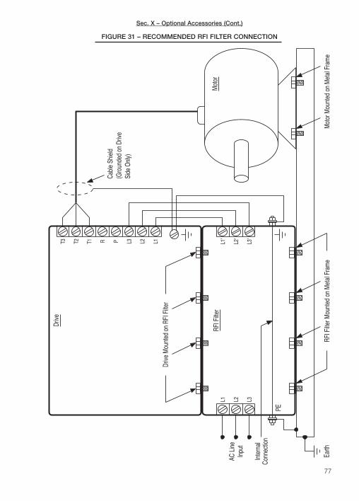
77
RFI F
ilter M
ount
ed o
n M
etal
Fra
me
Drive
Mou
nted
on
RFI F
ilter
Earth
Conn
ectio
n
PE
Inpu
tAC
Lin
e
Inte
rnal
L3L2L1RF
I Filte
r
Drive
Mot
or M
ount
ed o
n M
etal
Fra
me
Cabl
e Sh
ield
(Gro
unde
d on
Driv
eSi
de O
nly)
L3'
L2'
L1'
Mot
or
T1 L2 L1L3PRT2T3
FIGURE 31 – RECOMMENDED RFI FILTER CONNECTION
Sec. X – Optional Accessories (Cont.)

Sec. X – Optional Accessories (Cont.)
78
B. Brake Resistor Kit – Provides quicker stopping with high inertial loads. This option is onlyavailable for Models KBN2-2250-1, 2201-1, 2202-1, 2203-1, 2305-1, 2307-1, 2310-1,4301-1, 4302-1, 4303-1, 4305-1, 4307-1, 4310-1. See Table 25.
DriveModel No.
MotorHP (kw)
BrakingTorque
(%)
Brake Resistor
PartNo.
Ω WDimensions (W x H x L)
Inches mm
KBN2-2250-1 .5 ( .37) 220 14170 200 60 1.57 x 0.79 x 4.53 40 x 20 x 115
KBN2-2201-1 1 (.75) 220 14170 200 60 1.57 x 0.79 x 4.53 40 x 20 x 115
KBN2-2202-1 2 (1.5) 120 14180 100 150 1.57 x 0.79 x 8.46 40 x 20 x 215
KBN2-2203-1 3 (2.2) 115 14190 70 200 2.36 x 1.18 x 6.49 60 x 30 x 165
KBN2-2305-1 5 (3.7) 120 14200 40 300 2.36 x 1.18 x 8.46 60 x 30 x 215
KBN2-2307-1 7.5 (5.6) 125 14210 25 500 2.36 x 1.18 x 13.19 60 x 30 x 335
KBN2-2310-1 10 (7.5) 120 14220 20 600 2.36 x 1.18 x 13.19 60 x 30 x 335
KBN2-4301-1 1 (0.75) 125 14230 750 60 1.57 x 0.79 x 4.53 40 x 20 x 115
KBN2-4302-1 2 (1.5) 120 14240 400 150 1.57 x 0.79 x 8.46 40 x 20 x 215
KBN2-4303-1 3 (2.2.) 130 14250 250 200 2.36 x 1.18 x 6.49 60 x 30 x 165
KBN2-4305-1 5 (3.7) 130 14260 150 300 2.36 x 1.18 x 8.46 60 x 30 x 215
KBN2-4307-1 7.5 (5.6) 125 14270 100 500 2.36 x 1.18 x 13.19 60 x 30 x 335
KBN2-4310-1 10 (7.5) 120 14280 80 600 2.36 x 1.18 x 13.19 60 x 30 x 335
TABLE 25 – BRAKE RESISTORS
Drive Model ClassInput
Phases(φ)
RatingKB Model No.
KB PartNo.
Dimensions (W x H x D)
Amps AC Volts AC Inches mm
KBN2-2250-1B 1 10 230 KBN2-EMI-2102 14020 4.49 x 7.83 x 1.18 114 x 199 x 30
KBN2-2201-1
KBN2-2202-1B 1 20 230
KBN2-EMI-2202A 14030 6.26 x 8.98 x 1.97 159 x 228 x 50
KBN2-2203-1 KBN2-EMI-2202B 14040 7.68 x 10.43 x 1.97 195 x 265 x 50
KBN2-4301-1B 3 10 460 KBN2-EMI-4103A 14050 6.26 x 8.98 x 1.97 159 x 228 x 45
KBN2-4302-1
KBN2-4303-1B 3 10 460 KBN2-EMI-4103B 14060 7.68 x 10.43 x 1.97 195 x 265 x 45
KBN2-4305-1
KBN2-4307-1 B3 20 460 KBN2-EMI-4203 14070 8.27 x 14.17 x 2.76 210 x 360 x 70
KBN2-4310-1 A
KBN2-4315-1
A 3 60 460 KBN2-EMI-4603 14080 10.24 x 18.11 x 3.94 260 x 460 x 100KBN2-4320-1
KBN2-4330-1
TABLE 24 – RFI FILTERS
Note: Class A RFI Filter complies with Industrial Standard and Class B RFI Filter complies with Residential Standard.
C. Digital Keypad Extension Cable Kit – 3 Ft. (1m) and 10 Ft. (3m) extension cablesprovide remote mounting of the digital keypad. See Table 26, on page 79.

Sec. X – Optional Accessories (Cont.)
D. External Speed Potentiometer Kit (Part No. 9111) – Provides remote mounting of thespeed potentiometer to control motor speed. Kit includes a linear 5 kΩ potentiometer,mounting hardware, and panel insulator.
E. RS-232 Communication Kit (Part No. 14150) and RS-485 Communication Kit(Part No. 14160) – Provides PC Windows® based RS-232/485 DriveLink™ softwarecommunications to facilitate programming.
F. DownLoad Module™ (DLM) (Part No. 14145) – Handheld programming device uploadsand downloads drive programs.
79
DriveModel No
Extension Cable Kit Part No.
3 Ft. (1m) 6 Ft. (2 m) 10 Ft. (3 m)
KBN2-2250-1
14090 14100 14110
KBN2-2201-1
KBN2-2202-1
KBN2-2203-1
KBN2-2305-1
KBN2-2307-1
14120 14130 14140
KBN2-2310-1
KBN2-2315-1
KBN2-2320-1
KBN2-2330-1
TABLE 26 – EXTENSION CABLES
DriveModel No
Extension Cable Kit Part No.
3 Ft. (1 m) 6 Ft. (2 m) 10 Ft. (3 m)
KBN2-4301-1
14090 14100 14110KBN2-4302-1
KBN2-4303-1
KBN2-4305-1
KBN2-4307-1
14120 14130 14140
KBN2-4310-1
KBN2-4315-1
KBN2-4320-1
KBN2-4330-1

XI. LIMITED WARRANTYFor a period of 18 months from the date of original purchase, KB Electronics, Inc. will repair orreplace, without charge, devices which our examination proves to be defective in material orworkmanship. This warranty is valid if the unit has not been tampered with by unauthorized per-sons, misused, abused, or improperly installed and has been used in accordance with theinstructions and/or ratings supplied. The foregoing is in lieu of any other warranty or guarantee,expressed or implied. KB Electronics, Inc. is not responsible for any expense, including installa-tion and removal, inconvenience, or consequential damage, including injury to any person,caused by items of our manufacture or sale. Some states do not allow certain exclusions or lim-itations found in this warranty and therefore they may not apply to you. In any event, the totalliability of KB Electronics, Inc., under any circumstance, shall not exceed the full purchase priceof this product. (rev 2/2000)
KB Electronics, Inc.12095 NW 39th Street, Coral Springs, FL 33065-2516 • (954) 346-4900 • Fax (954) 346-3377Outside Florida Call TOLL FREE (800) 221-6570 • E-mail – [email protected]
COPYRIGHT © 2003 by KB ELECTRONICS, INC.
All rights reserved. In accordance with the United States Copyright Act of 1976, no part of thispublication may be reproduced in any form or by any means without permission in writing fromKB Electronics, Inc. (8/22/02)
(A98020) – Rev. C – 4/2003