Installation and Operation Manual H50 Series Gas...
54
Frymaster, a member of the Commercial Food Equipment Service Association, recommends using CFESA Certified Technicians. 24-Hour Service Hotline 1-800-551-8633 APRIL 2004 *8195000* H50 Series Gas Fryers Installation and Operation Manual
Transcript of Installation and Operation Manual H50 Series Gas...

Frymaster, a member of the Commercial Food Equipment Service Association, recommendsusing CFESA Certified Technicians.
24-Hour Service Hotline 1-800-551-8633 APRIL 2004*8195000*
H50 Series G
as FryersInstallation and O
peration Manual
NOTICEThis appliance is intended for professional use only and is to be operated by qualifiedpersonnel only. A Frymaster/DEAN Factory Authorized Service Center (FASC) or other qualifiedprofessional should perform installation, maintenance, and repairs. Installation, maintenance,or repairs by unqualified personnel may void the manufacturer’s warranty. See Chapter 1 ofthis manual for definitions of qualified personnel.
NOTICEThis equipment must be installed in accordance with the appropriate national and local codes ofthe country and/or region in which the appliance is installed. See NATIONAL CODEREQUIREMENTS in Chapter 2 of this manual for specifics.
NOTICE TO U.S. CUSTOMERSThis equipment is to be installed in compliance with the basic plumbing code of the BuildingOfficials and Code Administrators International, Inc. (BOCA) and the Food Service SanitationManual of the U.S. Food and Drug Administration.
NOTICEDrawings and photos used in this manual are intended to illustrate operational, cleaning andtechnical procedures and may not conform to onsite management operational procedures.
NOTICE TO OWNERS OF UNITS EQUIPPED WITH COMPUTERS
U.S.This device complies with Part 15 of the FCC rules. Operation is subject to the following twoconditions: 1) This device may not cause harmful interference, and 2) This device must acceptany interference received, including interference that may cause undesired operation. Whilethis device is a verified Class A device, it has been shown to meet the Class B limits.
CANADAThis digital apparatus does not exceed the Class A or B limits for radio noise emissions as setout by the ICES-003 standard of the Canadian Department of Communications.Cet appareil numerique n’emet pas de bruits radioelectriques depassany les limites de classe Aet B prescrites dans la norme NMB-003 edictee par le Ministre des Communcations du Canada.
DANGERImproper installation, adjustment, maintenance or service, and unauthorized alterations ormodifications can cause property damage, injury, or death. Read the installation, operating,and service instructions thoroughly before installing or servicing this equipment. Only qualifiedservice personnel may convert this appliance to use a gas other than that for which it wasoriginally configured.
DANGERNo structural material on the fryer should be altered or removed to accommodate placement ofthe fryer under a hood. Questions? Call the Frymaster/Dean Service Hotline at 1-800-551-8633.
DANGER Adequate means must be provided to limit the movement of this appliance without depending upon the gas line connection. Single fryers equipped with legs must be stabilized by installing anchor straps. All fryers equipped with casters must be stabilized by installing restraining chains. If a flexible gas line is used, an additional restraining cable must be connected at all times when the fryer is in use.
DANGER The front ledge of the fryer is not a step! Do not stand on the fryer. Serious injury can result from slips or contact with the hot oil.
DANGER Do not store or use gasoline or other flammable liquids or vapors in the vicinity of this or any other appliance.
DANGER Instructions to be followed in the event the operator smells gas or otherwise detects a gas leak must be posted in a prominent location. This information can be obtained from the local gas company or gas supplier.
DANGER
This product contains chemicals known to the state of California to cause cancer and/or birth defects or other reproductive harm. Operation, installation, and servicing of this product could expose you to airborne particles of glasswool or ceramic fibers, crystalline silica, and/or carbon monoxide. Inhalation of airborne particles of glasswool or ceramic fibers is known to the State of California to cause cancer. Inhalation of carbon monoxide is known to the State of California to cause birth defects or other reproductive harm.
DANGER The crumb tray in fryers equipped with a filter system must be emptied into a fireproof container at the end of frying operations each day. Some food particles can spontaneously combust if left soaking in certain shortening material.
WARNING
Do not bang fry baskets or other utensils on the fryer’s joiner strip. The strip is present to seal the joint between the fry vessels. Banging fry baskets on the strip to dislodge shortening will distort the strip, adversely affecting its fit. It is designed for a tight fit and should only be removed for cleaning.
NOTICE
The Commonwealth of Massachusetts requires any and all gas products to be installed by a licensed plumber or pipe fitter.

THIS PAGE INTENTIONALLY LEFT BLANK.
i
H50 SERIES GAS FRYER INSTALLATION & OPERATION MANUAL
TABLE OF CONTENTS
CHAPTER 1: General Information1.1 Parts Ordering and Service Information............................................................................ 1-11.2 Safety Information............................................................................................................. 1-11.3 European Community (CE) Specific Information............................................................. 1-21.4 Equipment Description...................................................................................................... 1-31.5 Installation, Operating, and Service Personnel ................................................................. 1-31.6 Definitions ......................................................................................................................... 1-31.7 Shipping Damage Claim Procedure .................................................................................. 1-4
CHAPTER 2: Installation Instructions2.1 General Installation Requirements .................................................................................... 2-12.2 Caster/Leg Installation ...................................................................................................... 2-32.3 Pre-Connection Preparations............................................................................................. 2-32.4 Connection to Gas Line..................................................................................................... 2-42.5 Converting to Another Gas Type ...................................................................................... 2-7
CHAPTER 3: Operating Instructions3.1 Start-Up Procedure ............................................................................................................ 3-23.2 Boiling Out the Frypot ...................................................................................................... 3-33.3 Shutting the Fryer Down ................................................................................................... 3-53.4 Controller Operation and Programming............................................................................ 3-5
CHAPTER 4: Filtration Instructions4.1 Draining and Manual Filtering .......................................................................................... 4-14.2 Built-In Filtration System Operation................................................................................. 4-2
Preparing the Filter Unit for Use....................................................................................... 4-2Operation of the Filter Unit ............................................................................................... 4-4Changing the Filter Paper.................................................................................................. 4-6
CHAPTER 5: Preventive Maintenance5.1 Fryer Preventive Maintenance Checks and Service .......................................................... 5-1
Daily Checks and Service.................................................................................................. 5-1Weekly Checks and Service .............................................................................................. 5-1Monthly Checks and Service............................................................................................. 5-3Quarterly Checks and Service ........................................................................................... 5-4Semi-Annual Checks and Service ..................................................................................... 5-7
5.2 Built-In Filtration System Preventive Maintenance Checks and Service ......................... 5-85.3 Annual/Periodic System Inspection .................................................................................. 5-9
CHAPTER 6: Operator Troubleshooting6.1 Introduction ....................................................................................................................... 6-16.2 Troubleshooting Fryers with Computer Magic III, Basket Lift Timer, or Digital
Controller........................................................................................................................... 6-26.3 Troubleshooting Fryers with Solid State (Analog) Controller .......................................... 6-46.4 Troubleshooting the Built-In Filtration System ................................................................ 6-66.5 Troubleshooting the Basket Lift........................................................................................ 6-66.6 Replacing the Ignition Module Fuse ................................................................................. 6-76.7 Replacing the Controller or Controller Wiring Harness ................................................... 6-8

THIS PAGE INTENTIONALLY LEFT BLANK.
1-1
H50 SERIES GAS FRYERCHAPTER 1: GENERAL INFORMATION
1.1 Applicability and Validity
The (insert equipment family) model family has been approved by the European Union forsale and installation in the following EU countries: AT, BE, DE, DK, ES, FI, FR, GB, IE, IT,LU, NL, NO, PT and SE.
This manual is applicable to and valid for all (insert equipment family) units sold in English-speaking countries, including those in the European Union. Where conflicts exist between in-structions and information in this manual and local or national codes of the country in whichthe equipment is installed, installation and operation shall comply with those codes.
This appliance is only for professional use and shall be used by qualified personnel only, asdefined in Section 1.7.
1.2 Parts Ordering and Service Information
In order to assist you quickly, the Frymaster Factory Authorized Service Center (FASC) or ServiceDepartment representative requires certain information about your equipment. Most of thisinformation is printed on a data plate affixed to the inside of the fryer door. Part numbers are foundin the Installation, Operation, Service, and Parts Manual. Parts orders may be placed directly withyour local FASC or distributor. Included with fryers when shipped from the factory is a list ofFrymaster FASCs. If you do not have access to this list, contact the Frymaster Service Departmentat 1-800-551-8633 or 1-318-865-1711.
When ordering parts, the following information is required:
Model Number:Serial Number:Type of Gas or Voltage:Item Part Number:Quantity Needed:
Service information may be obtained by contacting your local FASC/Distributor. Service may alsobe obtained by calling the Frymaster Service Department at 1-800-551-8633 or 1-318-865-1711.When requesting service, please have the following information ready:
Model Number:Serial Number:Type of Gas:
In addition to the model number, serial number, and type of gas, please be prepared to describe thenature of the problem and have ready any other information that you think may be helpful in solvingyour problem.
RETAIN AND STORE THIS MANUAL IN A SAFE PLACE FOR FUTURE USE.
1-2
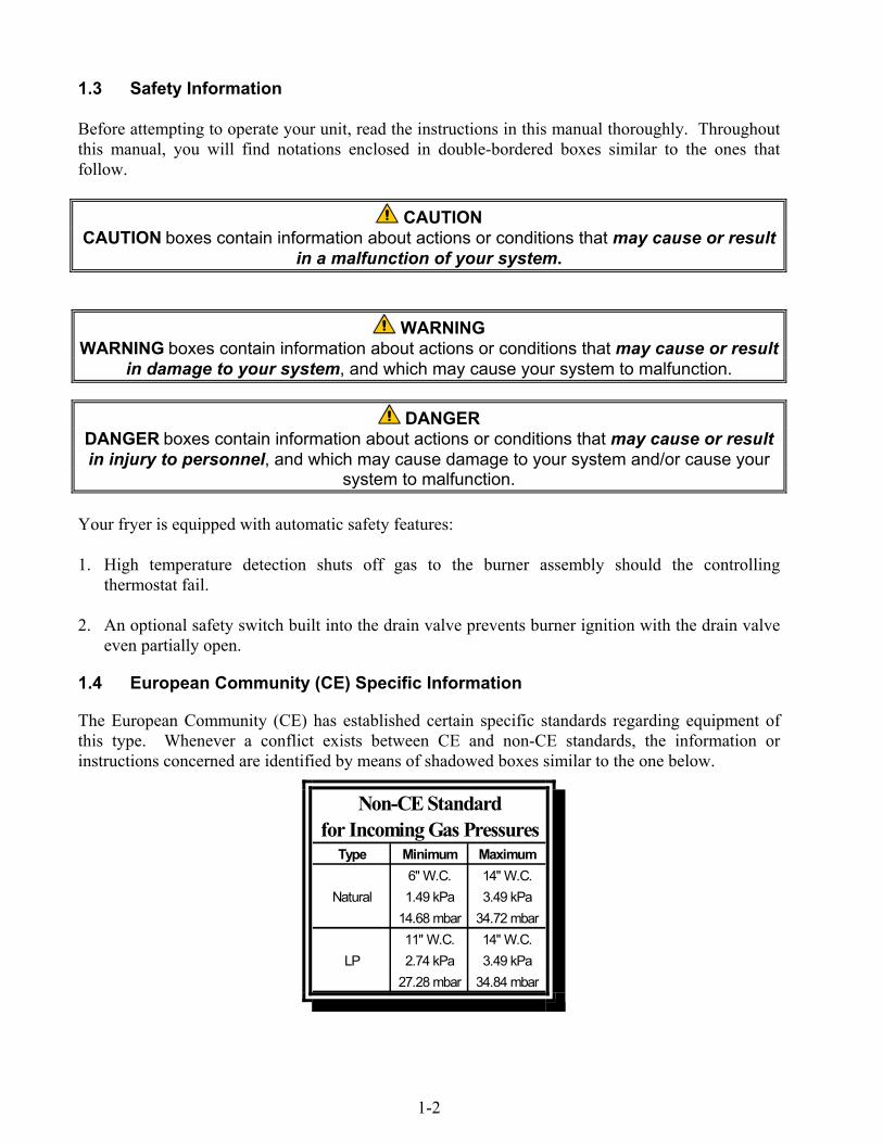
1.3 Safety Information
Before attempting to operate your unit, read the instructions in this manual thoroughly. Throughoutthis manual, you will find notations enclosed in double-bordered boxes similar to the ones thatfollow.
CAUTIONCAUTION boxes contain information about actions or conditions that may cause or result
in a malfunction of your system.
WARNINGWARNING boxes contain information about actions or conditions that may cause or result
in damage to your system, and which may cause your system to malfunction.
DANGERDANGER boxes contain information about actions or conditions that may cause or resultin injury to personnel, and which may cause damage to your system and/or cause your
system to malfunction.
Your fryer is equipped with automatic safety features:
1. High temperature detection shuts off gas to the burner assembly should the controllingthermostat fail.
2. An optional safety switch built into the drain valve prevents burner ignition with the drain valveeven partially open.
1.4 European Community (CE) Specific Information
The European Community (CE) has established certain specific standards regarding equipment ofthis type. Whenever a conflict exists between CE and non-CE standards, the information orinstructions concerned are identified by means of shadowed boxes similar to the one below.
Non-CE Standardfor Incoming Gas Pressures
Type Minimum Maximum6" W.C. 14" W.C.
Natural 1.49 kPa 3.49 kPa14.68 mbar 34.72 mbar11" W.C. 14" W.C.
LP 2.74 kPa 3.49 kPa27.28 mbar 34.84 mbar
1-3
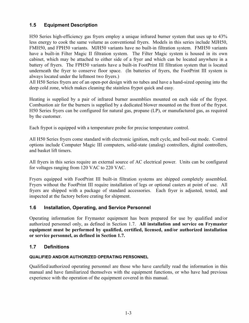
1.5 Equipment Description
H50 Series high-efficiency gas fryers employ a unique infrared burner system that uses up to 43%less energy to cook the same volume as conventional fryers. Models in this series include MJH50,FMH50, and FPH50 variants. MJH50 variants have no built-in filtration system. FMH50 variantshave a built-in Filter Magic II filtration system. The Filter Magic system is housed in its owncabinet, which may be attached to either side of a fryer and which can be located anywhere in abattery of fryers. The FPH50 variants have a built-in FootPrint III filtration system that is locatedunderneath the fryer to conserve floor space. (In batteries of fryers, the FootPrint III system isalways located under the leftmost two fryers.)All H50 Series fryers are of an open-pot design with no tubes and have a hand-sized opening into thedeep cold zone, which makes cleaning the stainless frypot quick and easy.
Heating is supplied by a pair of infrared burner assemblies mounted on each side of the frypot.Combustion air for the burners is supplied by a dedicated blower mounted on the front of the frypot.H50 Series fryers can be configured for natural gas, propane (LP), or manufactured gas, as requiredby the customer.
Each frypot is equipped with a temperature probe for precise temperature control.
All H50 Series fryers come standard with electronic ignition, melt cycle, and boil-out mode. Controloptions include Computer Magic III computers, solid-state (analog) controllers, digital controllers,and basket lift timers.
All fryers in this series require an external source of AC electrical power. Units can be configuredfor voltages ranging from 120 VAC to 220 VAC.
Fryers equipped with FootPrint III built-in filtration systems are shipped completely assembled.Fryers without the FootPrint III require installation of legs or optional casters at point of use. Allfryers are shipped with a package of standard accessories. Each fryer is adjusted, tested, andinspected at the factory before crating for shipment.
1.6 Installation, Operating, and Service Personnel
Operating information for Frymaster equipment has been prepared for use by qualified and/orauthorized personnel only, as defined in Section 1.7. All installation and service on Frymasterequipment must be performed by qualified, certified, licensed, and/or authorized installationor service personnel, as defined in Section 1.7.
1.7 Definitions
QUALIFIED AND/OR AUTHORIZED OPERATING PERSONNEL
Qualified/authorized operating personnel are those who have carefully read the information in thismanual and have familiarized themselves with the equipment functions, or who have had previousexperience with the operation of the equipment covered in this manual.
1-4
QUALIFIED INSTALLATION PERSONNEL
Qualified installation personnel are individuals, firms, corporations, and/or companies which, eitherin person or through a representative, are engaged in and are responsible for the installation of gas-fired appliances. Qualified personnel must be experienced in such work, be familiar with all gasprecautions involved, and have complied with all requirements of applicable national and localcodes.
QUALIFIED SERVICE PERSONNEL
Qualified service personnel are those who are familiar with Frymaster equipment and who have beenauthorized by Frymaster, L.L.C. to perform service on the equipment. All authorized servicepersonnel are required to be equipped with a complete set of service and parts manuals, and to stocka minimum amount of parts for Frymaster equipment. A list of Frymaster Factory AuthorizedService Centers (FASC) is included with the fryer when shipped from the factory. Failure to usequalified service personnel will void the Frymaster warranty on your equipment.
1.8 Shipping Damage Claim Procedure
Your Frymaster equipment was carefully inspected and packed before leaving the factory. Thetransportation company assumes full responsibility for safe delivery upon its acceptance of theequipment for transport.
What to do if your equipment arrives damaged:
1. File a claim for damages immediately, regardless of the extent of damages.
2. Inspect for and record all visible loss or damage, and ensure that this information is noted onthe freight bill or express receipt and is signed by the person making the delivery.
3. Concealed loss or damage that was unnoticed until the equipment was unpacked should berecorded and reported to the freight company or carrier immediately upon discovery. Aconcealed damage claim must be submitted within 15 days of the date of delivery. Ensure thatthe shipping container is retained for inspection.
Frymaster DOES NOT ASSUME RESPONSIBILITY FOR DAMAGE OR LOSSINCURRED IN TRANSIT.
2-1
H50 SERIES GAS FRYERCHAPTER 2: INSTALLATION INSTRUCTIONS
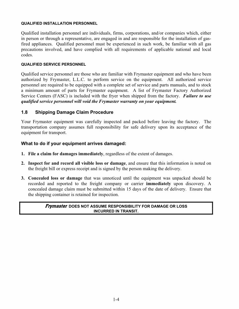
2.1 General Installation Requirements
Qualified, licensed, and/or authorized installation or service personnel, as defined in Section1.7 of this manual, should perform all installation and service on Frymaster equipment.
Conversion of this appliance from one type of gas to another should only be performed byqualified, licensed, and/or authorized installation or service personnel as defined in Section 1.7of this manual.
Failure to use qualified, licensed, and/or authorized installation or service personnel (as de-fined in Section 1.7 of this manual) to install, convert to another gas type or otherwise servicethis equipment will void the Frymaster warranty and may result in damage to the equipmentor injury to personnel.
Where conflicts exist between instructions and information in this manual and local or na-tional codes or regulations, installation and operation shall comply with the codes or regula-tions in force in the country in which the equipment is installed.
DANGERBuilding codes prohibit a fryer with its open tank of hot oil/shortening being installedbeside an open flame of any type, including those of broilers and ranges.
Upon arrival, inspect the cooker carefully for visible or concealed damage. (See Shipping DamageClaim Procedure in Chapter 1.)
DANGERFrymaster appliances equipped with legs are for stationary installations. Appliancesfitted with legs must be lifted during movement to avoid damage to the applianceand bodily injury. For movable installations, optional equipment casters must beused. Questions? Call 1-800-551-8633.
CLEARANCE AND VENTILATION
The fryer(s) must be installed with a 6” (150 mm) clearance at both sides and back when installedadjacent to combustible construction; no clearance is required when installed adjacent tononcombustible construction. A minimum of 24” (600 mm) clearance should be provided at thefront of the fryer.
DANGERNo structural material on the fryer should be altered or removed to accommodateplacement of the fryer under a hood. Questions? Call the Frymaster/Dean ServiceHotline at 1-800-551-8633.
2-2
One of the most important considerations of efficient fryer operation is ventilation. Make sure thefryer is installed so that products of combustion are removed efficiently, and that the kitchenventilation system does not produce drafts that interfere with burner operation.
The fryer flue opening must not be placed close to the intake of the exhaust fan, and the fryer mustnever have its flue extended in a “chimney” fashion. An extended flue will change the combustioncharacteristics of the fryer, causing longer recovery time. It also frequently causes delayed ignition.To provide the airflow necessary for good combustion and burner operation, the areas surroundingthe fryer front, sides, and rear must be kept clear and unobstructed.
DANGERThis appliance must be installed with sufficient ventilation to prevent the occurrenceof unacceptable concentrations of substances harmful to the health of personnel inthe room in which it is installed.
Fryers must be installed in an area with an adequate air supply and adequate ventilation. Adequatedistances must be maintained from the flue outlet of the fryer to the lower edge of the ventilationfilter bank. Filters should be installed at an angle of 45º. Place a drip tray beneath the lowest edgeof the filter. For U.S. installation, NFPA standard No. 96 states, “A minimum distance of 18 in.(450 mm) should be maintained between the flue outlet and the lower edge of the grease filter.”Frymaster recommends that the minimum distance be 24 in. (600 mm) from the flue outlet to thebottom edge of the filter when the appliance consumes more than 120,000 BTU per hour.
For installations in the United States, information on construction and installation of ventilatinghoods can be found in the NFPA standard cited above. A copy of the standard may be obtainedfrom the National Fire Protection Association, Battery March Park, Quincy, MA 02269.
NATIONAL CODE REQUIREMENTS
The type of gas for which the fryer is equipped is stamped on the data plate attached to the inside ofthe fryer door. Connect a fryer stamped “NAT” only to natural gas, those stamped “PRO” only topropane gas, and those stamped “MFG” only to manufactured gas.
Installation shall be made with a gas connector that complies with national and local codes, and,where applicable, CE codes. Quick-disconnect devices, if used, shall likewise comply with national,local, and, if applicable, CE codes.
ELECTRICAL GROUNDING REQUIREMENTS
All electrically operated appliances must be grounded in accordance with all applicable national andlocal codes, and, where applicable, CE codes. A wiring diagram is located on the inside of the fryerdoor. Refer to the rating plate on the inside of the fryer door for proper voltages.
DANGERThis appliance is equipped with a three-prong (grounding) plug for your protectionagainst electrical shock, and must be plugged directly into a properly groundedthree-prong receptacle. Do not cut, remove, or otherwise bypass the groundingprong on this plug!
2-3
DANGERThis appliance requires electrical power for operation. Place the gas control valve inthe OFF position in case of a prolonged power outage. Do not attempt to operatethis appliance during a power outage.
AUSTRALIAN REQUIREMENTS
To be installed in accordance with AS 5601 / AG 601, local authority, gas, electricity, and any otherrelevant statutory regulations.
FCC COMPLIANCE
The user is cautioned that any changes or modifications to Frymaster computers not expresslyapproved by the party responsible for compliance could void the user’s authority to operate theequipment.
Frymaster computers have been tested and found to comply with the limits for a Class A digitaldevice, pursuant to Part 15 of the FCC rules. While these devices are verified as Class A devices,they have been shown to meet the Class B limits. These limits are designed to provide reasonableprotection against harmful interference when the equipment is operated in a commercialenvironment. This equipment generates, uses, and can radiate radio frequency energy and, if notinstalled and used in accordance with the instruction manual, may cause harmful interference toradio communications. Operation of the equipment in a residential area is likely to cause harmfulinterference in which case the user will be required to correct the interference at his own expense.
The user may find the booklet “How to Identify and Resolve Radio-TV Interference Problems”helpful. It is prepared by the Federal Communications Commission and is available from the U.S.Government Printing Office, Washington, DC 20402, Stock No. 004-000-00345-4.If necessary, the user should consult the dealer or an experienced radio and television technician foradditional suggestions.
2.2 Caster/Leg Installation
Depending upon the specific configuration ordered, your fryer may have been shipped withoutinstalled casters or legs. DO NOT INSTALL THIS APPLIANCE WITHOUT CASTERS ORLEGS. If the appliance requires the installation of casters or legs, install them in accordancewith the instructions included in your accessory package.
2.3 Pre-Connection Preparations
DANGERDO NOT connect this appliance to the gas supply before completing each step inthis section.
After the fryer has been positioned under the exhaust hood, ensure the following has beenaccomplished:
1. Adequate means must be provided to limit the movement of fryers without depending upon thegas line connections. If a flexible gas hose is used, a restraining cable must be connected at all

2-4
times when the fryer is in use. The restraining cable and installation instructions are packed withthe flexible hose in the accessories box that was shipped with your unit.
2. Single unit fryers must be stabilized by installing restraining chains on fryers equipped withcasters or anchor straps on fryers equipped with legs. Follow the instructions in the accessorypack to install the chains or straps.
DANGERDo not attach an apron drainboard to a single fryer. The fryer may become unstable,tip over, and cause injury. The appliance area must be kept free and clear ofcombustible material at all times.
3. Level fryers equipped with legs by screwing out the legs approximately 1 inch then adjustingthem so that the fryer is level and at the proper height in the exhaust hood. Frymasterrecommends that the minimum distance from the flue outlet to the bottom edge of the hood be 24in. (600 mm) when the appliance consumes more than 120,000 BTU per hour. NOTE: Thereare no built-in leveling devices on fryers equipped with casters. The floor where the fryer is tobe installed must be level.
4. Test the fryer electrical system:
a. Plug the fryer electrical cord(s) into a grounded electrical receptacle.b. Place the power switch in the ON position.
• For fryers equipped with solid-state (analog) controls, verify that the power and heatlights are lit.
• For fryers having computer or digital displays, verify that the display indicates CYCL.
c. Place the fryer power switch in the OFF position. Verify that the power and heat lights areout, or that the display is blank.
5. Refer to the data plate on the inside of the fryer door to determine if the fryer burner isconfigured for the proper type of gas before connecting the fryer quick-disconnect device orpiping from the gas supply line.
6. Verify the minimum and maximum gas supply pressures for the type of gas to be used inaccordance with the accompanying tables.
Orifice DiameterSingle
VatDualVat
SingleVat
DualVat
G20 20 2 x 3.40 2 x 3.40 7 mbar 7 mbarG25 20 or 25 2 x 3.40 2 x 3.40 10 mbar 10 mbarG30 28/30 or 50 2 x 2.05 2 x 2.05 17 mbar 17 mbarG31 37 or 50 2 x 2.05 2 x 2.05 20 mbar 20 mbar
CE Standardfor Incoming Gas Pressures
for Fryers Manufactured After April 1999
(1) mbar = 10,2 mm H2O
GasPressure(mbar)(1)
Regulator Pressure
Orifice DiameterSingle
VatDualVat
SingleVat
DualVat
G20 20 2 x 3.40 2 x 3.40 7 mbar 7 mbarG25 20 or 25 2 x 3.40 2 x 3.40 10 mbar 9 mbarG30 28/30 or 50 2 x 2.05 2 x 2.05 17 mbar 16,5 mbarG31 37 or 50 2 x 2.05 2 x 2.05 20,2 mbar 18,5 mbar
CE Standardfor Incoming Gas Pressures
for Fryers Manufactured Through April 1999
(1) mbar = 10,2 mm H2O
GasPressure(mbar)(1)
Regulator Pressure

2-5
Non-CE Standardfor Incoming Gas Pressures
Gas Minimum Maximum
Natural6" W.C.1.49 kPa
14.93 mbar
14" W.C.3.48 kPa
34.84 mbar
LP11" W.C.2.74 kPa
27.37 mbar
14" W.C.3.48 kPa
34.84 mbar
7. For fryers equipped with a FootPrint III system or basket lifts, plug the electrical cord(s) into apower receptacle behind the fryer.
2.4 Connection to Gas Line
DANGERBefore connecting new pipe to this appliance, the pipe must be blown out thor-oughly to remove all foreign material. Foreign material in the burner and gas con-trols will cause improper and dangerous operation.
DANGERWhen pressure-testing incoming gas supply lines, disconnect the fryer from the gasline if the test pressure will be ½ PSIG (3.45 kPa, 13.84 inches W.C.) or greater toavoid damage to the fryer’s gas tubes and gas valve(s).
DANGERAll connections must be sealed with a joint compound suitable for the gas beingused and all connections must be tested with a solution of soapy water before light-ing any pilots.
Never use matches, candles, or any other ignition source to check for leaks. If gasodors are detected, shut off the gas supply to the appliance at the main shut-offvalve and immediately contact the local gas company or an authorized serviceagency for service.
DANGER “Dry-firing” your unit will cause damage to the frypot and can cause a fire. Alwaysensure that melted shortening, cooking oil, or water is in the frypot before firing theunit.
The size of the gas line used for installation is very important. If the line is too small, the gaspressure at the burner manifold will be low. This may cause slow recovery and delayed ignition.The incoming gas supply line should be a minimum of 1½” (38 mm) in diameter. Refer to the charton the following page for the minimum sizes of connection piping.

2-6
Gas Connection Pipe Sizes(Minimum incoming pipe size should be 1 1/2" (41 mm))
Natural 3/4" (22 mm) 1" (28 mm) 1 1/4" (36 mm)Propane 1/2" (15 mm) 3/4" (22 mm) 1" (28 mm)Manufactured 1" (28 mm) 1 1/4" (36 mm) 1 1/2" (41 mm)
Gas Single Unit 2 - 3 Units4 or more
units*
* For distances of more than 20 feet (6 m) and/or morethan 4 fittings or elbows, increase the connection by onepipe size.
The H50 Series has received the CE mark for the countries and gas categories indicated in the tablebelow. NOTE: The nominal heat input (QN) is 21kW except for AT, DE, LU and category 3P/B,which is 23kW.
COUNTRIES CATEGORIES GAS PRESSURE (MBAR)G20 20AUSTRIA (AT) II2H3B/P G30, G31 50
I2E(R)B G20, G25 20, 25BELGIUM (BE) I3+ G30, G31 28-30, 37G20 20DENMARK (DK) II2H3B/P G30, G31 30
G20, G25 20, 25II2Esi3+ G30, G31 28-30, 37G20, G25 20, 25FRANCE (FR)
II2Esi3P G31 50G20 20FINLAND (FI) II2H3B/P G30, G31 30
G20, G25 20II2ELL3B/P G30, G31 50GERMANY (DE)I3P G31 50
G20 20GREECE (GR) II2H3+ G30, G31 28-30, 37G20 20ITALY (IT) II2H3+ G30, G31 28-30, 37G20 20IRELAND (IE) II2H3+ G30, G31 28-30, 37G20 20LUXEMBOURG (LU) II2E3B/P G30, G31 50G25 25II2L3P G31 50G25 25NETHERLANDS (NL)
II2L3B/P G30, G31 30NORWAY (NO) I3B/P G30, G31 30
G20 20PORTUGAL (PT) II2H3+ G30, G31 28-30, 37G20 20II2H3+ G30, G31 28-30, 37G20 20SPAIN (ES)
II2H3P G31 37, 50G20 20SWEDEN (SE) II2H3B/P G30, G31 30G20 20UNITED KINGDOM (UK) II2H3+ G30, G31 28-30, 37
CE StandardRequired airflow for the combustion air supply is 2m3/h per kW.
CE Approved Gas Categories by Country
2-7
1. Connect the quick-disconnect hose to the fryer quick-disconnect fitting under the front of thefryer and to the building gas line.
NOTE: Some fryers are configured for a rigid connection to the gas supply line. These unitsare connected to the gas supply line at the rear of the unit.
When using thread compound, use very small amounts on male threads only. Use a pipe threadcompound that is not affected by the chemical action of LP gases (Loctite™ PST56765 Sealantis one such compound). DO NOT apply compound to the first two threads. Doing so may allowsome of the compound to enter the gas stream, resulting in clogging of burner orifices and/or thecontrol valve.
2. Open the gas supply to the fryer and check all piping, fittings, and gas connections for leaks. Asoap solution should be used for this purpose.
3. Close the fryer drain valve and fill the frypot with water and boil-out solution to the bottomOIL LEVEL line at the rear of the frypot. Light the fryer and perform the boil-out proceduresthat are described in the “Lighting Instructions” and “Boiling Out the Frypot” topics found inChapter 3 of this manual.
DANGER “Dry-firing” your unit will cause damage to the frypot and can cause a fire. Alwaysensure that melted shortening, cooking oil, or water is in the frypot before firing yourunit.
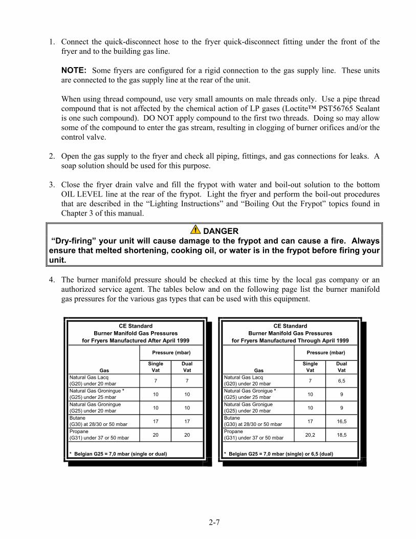
4. The burner manifold pressure should be checked at this time by the local gas company or anauthorized service agent. The tables below and on the following page list the burner manifoldgas pressures for the various gas types that can be used with this equipment.
GasSingle
VatDualVat
Natural Gas Lacq(G20) under 20 mbar 7 7
Natural Gas Groningue *(G25) under 25 mbar 10 10
Natural Gas Groningue(G25) under 20 mbar 10 10
Butane(G30) at 28/30 or 50 mbar 17 17
Propane(G31) under 37 or 50 mbar 20 20
CE StandardBurner Manifold Gas Pressures
for Fryers Manufactured After April 1999
Pressure (mbar)
* Belgian G25 = 7,0 mbar (single or dual)
GasSingle
VatDualVat
Natural Gas Lacq(G20) under 20 mbar 7 6,5
Natural Gas Gronigue *(G25) under 25 mbar 10 9
Natural Gas Gronigue(G25) under 20 mbar 10 9
Butane(G30) at 28/30 or 50 mbar 17 16,5
Propane(G31) under 37 or 50 mbar 20,2 18,5
CE StandardBurner Manifold Gas Pressures
for Fryers Manufactured Through April 1999
Pressure (mbar)
* Belgian G25 = 7,0 mbar (single) or 6,5 (dual)
2-8
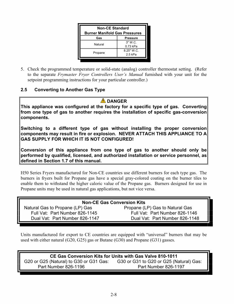
Gas Pressure
Natural 3" W.C.0.73 kPa
Propane8.25" W.C.
2.5 kPa
Non-CE StandardBurner Manifold Gas Pressures
5. Check the programmed temperature or solid-state (analog) controller thermostat setting. (Referto the separate Frymaster Fryer Controllers User’s Manual furnished with your unit for thesetpoint programming instructions for your particular controller.)
2.5 Converting to Another Gas Type
DANGERThis appliance was configured at the factory for a specific type of gas. Convertingfrom one type of gas to another requires the installation of specific gas-conversioncomponents.
Switching to a different type of gas without installing the proper conversioncomponents may result in fire or explosion. NEVER ATTACH THIS APPLIANCE TO AGAS SUPPLY FOR WHICH IT IS NOT CONFIGURED!
Conversion of this appliance from one type of gas to another should only beperformed by qualified, licensed, and authorized installation or service personnel, asdefined in Section 1.7 of this manual.
H50 Series Fryers manufactured for Non-CE countries use different burners for each type gas. Theburners in fryers built for Propane gas have a special gray-colored coating on the burner tiles toenable them to withstand the higher caloric value of the Propane gas. Burners designed for use inPropane units may be used in natural gas applications, but not vice versa.
Non-CE Gas Conversion KitsNatural Gas to Propane (LP) Gas Propane (LP) Gas to Natural Gas
Full Vat: Part Number 826-1145 Full Vat: Part Number 826-1146Dual Vat: Part Number 826-1147 Dual Vat: Part Number 826-1148
Units manufactured for export to CE countries are equipped with “universal” burners that may beused with either natural (G20, G25) gas or Butane (G30) and Propane (G31) gasses.
CE Gas Conversion Kits for Units with Gas Valve 810-1011G20 or G25 (Natural) to G30 or G31 Gas: G30 or G31 to G20 or G25 (Natural) Gas:
Part Number 826-1196 Part Number 826-1197
2-9
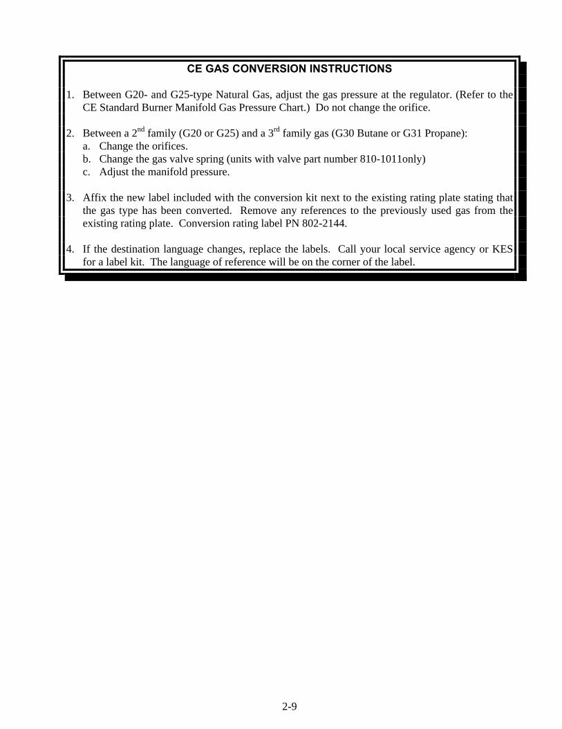
CE GAS CONVERSION INSTRUCTIONS 1. Between G20- and G25-type Natural Gas, adjust the gas pressure at the regulator. (Refer to the
CE Standard Burner Manifold Gas Pressure Chart.) Do not change the orifice. 2. Between a 2nd family (G20 or G25) and a 3rd family gas (G30 Butane or G31 Propane): a. Change the orifices. b. Change the gas valve spring (units with valve part number 810-1011only) c. Adjust the manifold pressure. 3. Affix the new label included with the conversion kit next to the existing rating plate stating that
the gas type has been converted. Remove any references to the previously used gas from the existing rating plate. Conversion rating label PN 802-2144.
4. If the destination language changes, replace the labels. Call your local service agency or KES
for a label kit. The language of reference will be on the corner of the label.

THIS PAGE INTENTIONALLY LEFT BLANK.
3-1
H50 SERIES GAS FRYERCHAPTER 3: OPERATING INSTRUCTIONS
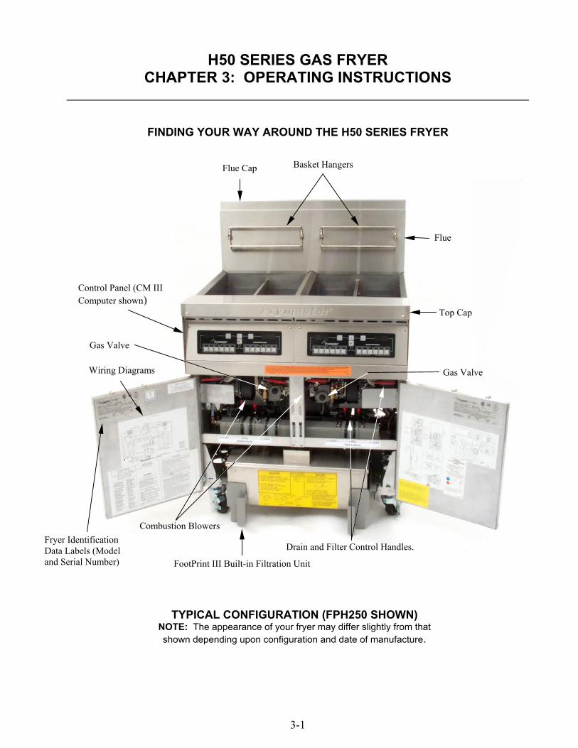
FINDING YOUR WAY AROUND THE H50 SERIES FRYER
Fryer IdentificationData Labels (Modeland Serial Number)
Control Panel (CM IIIComputer shown)
FootPrint III Built-in Filtration Unit
Basket HangersFlue Cap
Flue
Combustion Blowers
TYPICAL CONFIGURATION (FPH250 SHOWN)NOTE: The appearance of your fryer may differ slightly from thatshown depending upon configuration and date of manufacture.
Top Cap
Drain and Filter Control Handles.
Gas ValveWiring Diagrams
Gas Valve
3-2
3.1 Start-Up Procedure
WARNINGThe on-site supervisor is responsible for ensuring that operators are made aware ofthe inherent hazards of operating a hot oil filtering system, particularly the aspectsof oil filtration, draining and cleaning procedures.
CAUTIONIf this is the first time the fryer is being used after installation, refer to Section 3.2,Boil-Out Procedure.
CAUTIONThe cooking oil/shortening capacity of the H50 Series fryer is 50 lbs. (25 liters) at70ºF (21ºC) for a full-vat and 25 lbs. (12.5 liters) at 70ºF (21ºC) for each half of adual-vat.
Before lighting the fryer, make sure the fryer is OFF and the frypot drain valve(s)is/are closed. Remove the basket support rack(s), if installed, and fill the frypot tothe bottom OIL-LEVEL line.
If solid shortening is being used, make sure it is packed down into the bottom of thefrypot.
WARNINGNever operate this appliance with an empty frypot. The frypot must be filled with wa-ter or cooking oil/shortening before lighting the burners. Failure to do so will dam-age the frypot and may cause a fire.
Lighting the Fryer
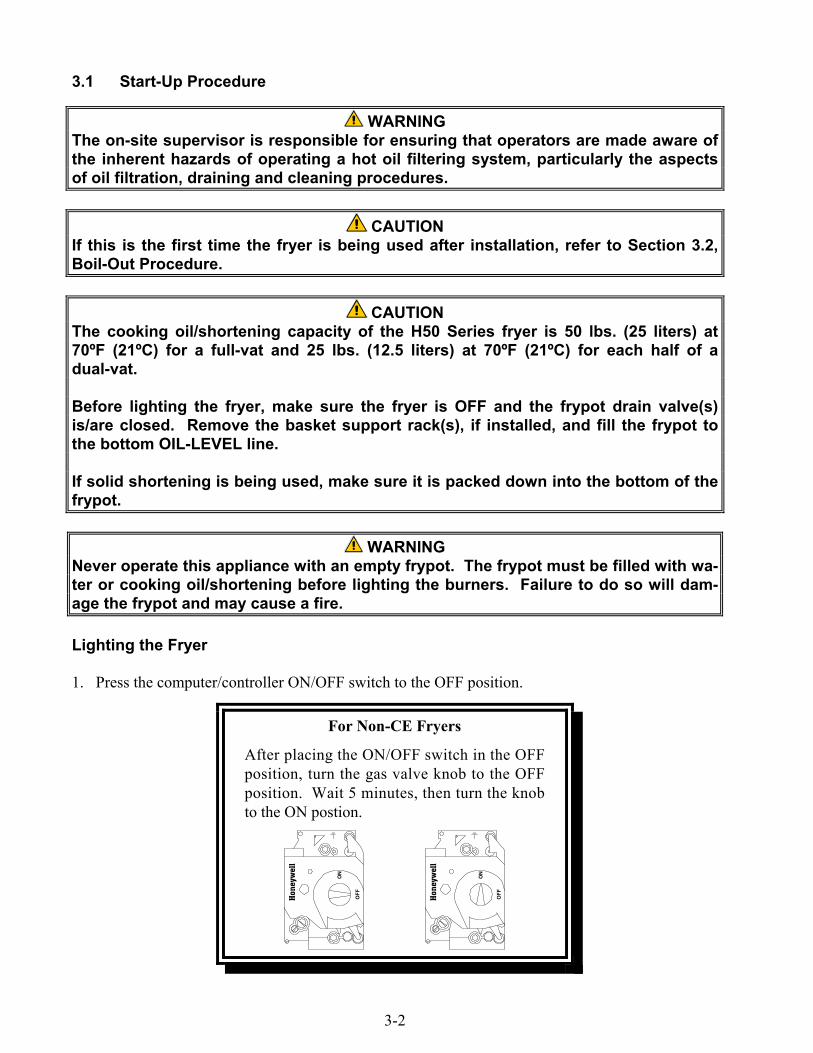
1. Press the computer/controller ON/OFF switch to the OFF position.
Honeywell
ON
OFF
Honeywell
ON
OFF
For Non-CE Fryers
After placing the ON/OFF switch in the OFFposition, turn the gas valve knob to the OFFposition. Wait 5 minutes, then turn the knobto the ON postion.
3-3
2. Press the computer/controller ON/OFF switch to the ON position and set the thermostat orprogram the computer for normal cooking temperature.
3. If the burners fail to light, press the ON/OFF switch to the OFF position and wait 60 seconds.Repeat step 2.
4. The fryer will automatically enter the Melt cycle mode if the frypot temperature is below 180ºF(82ºC). (NOTE: During the melt cycle, the burners will repeatedly fire for a few seconds, thengo out for a longer period.) When the frypot temperature reaches 180ºF (82ºC), the unit willautomatically switch to the Heating mode. The burners will remain lit until the frypottemperature reaches the programmed cooking temperature.
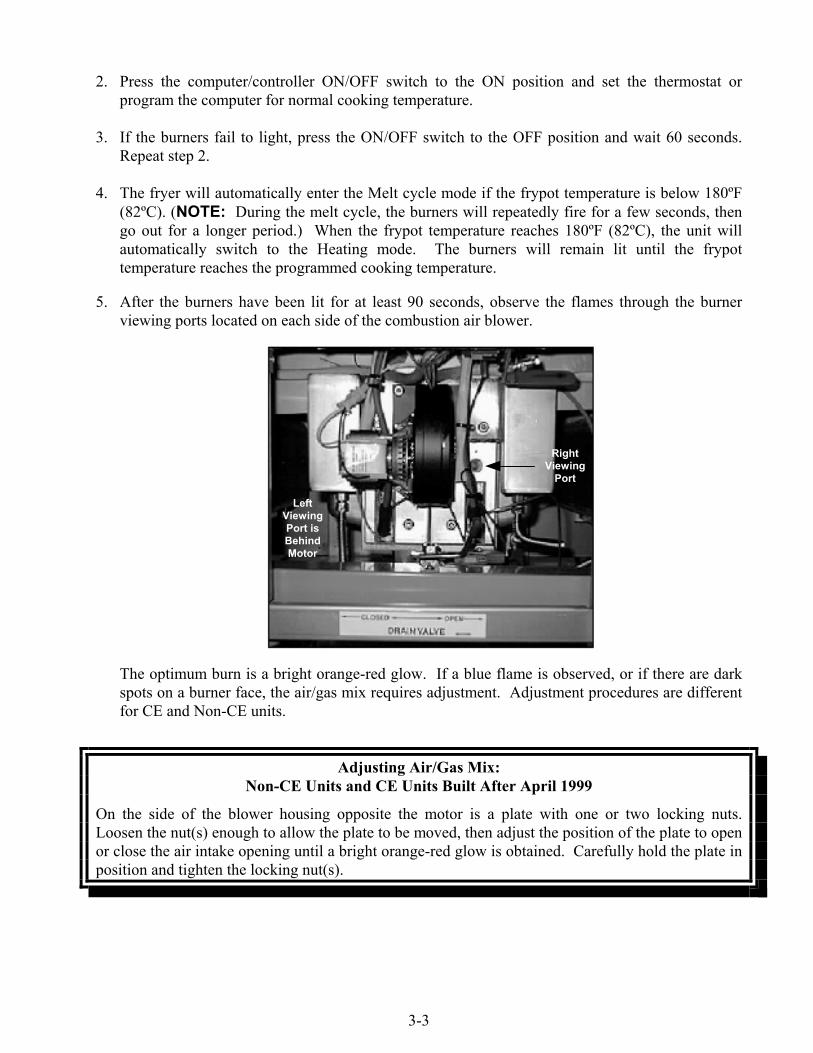
5. After the burners have been lit for at least 90 seconds, observe the flames through the burnerviewing ports located on each side of the combustion air blower.
The optimum burn is a bright orange-red glow. If a blue flame is observed, or if there are darkspots on a burner face, the air/gas mix requires adjustment. Adjustment procedures are differentfor CE and Non-CE units.
Adjusting Air/Gas Mix:Non-CE Units and CE Units Built After April 1999
On the side of the blower housing opposite the motor is a plate with one or two locking nuts.Loosen the nut(s) enough to allow the plate to be moved, then adjust the position of the plate to openor close the air intake opening until a bright orange-red glow is obtained. Carefully hold the plate inposition and tighten the locking nut(s).
LeftViewingPort isBehindMotor
RightViewing
Port
3-4
Adjusting Air/Gas Mix:CE Units Built Before May 1999
CE units built before May 1999 are equipped with a shield assembly in front of the blowers. An airshutter plate on the face of the shield assembly regulates the amount of airflow to the blower intake.To adjust the shutter plate, loosen the locking screws and slide the shutter to the left or right asnecessary to obtain a bright orange-red glow. Carefully hold the shutter plate in position and tightenthe locking screws.
3.2 Boiling Out the Frypot
To ensure that the frypot is free of any contamination resulting from its manufacture, shipping, andhandling during installation, the frypot must be boiled out before first use. Frymaster recommendsboiling out the frypot each time the oil or shortening is changed.
1. Before lighting the burners, close the fryer drain valve(s) and fill the frypot to the bottomOIL-LEVEL line with a mixture of cold water and automatic dishwasher detergent.
2. For units equipped with a Solid State (Analog) controller, set the temperature knob to 195°F(91°C)
For units equipped with a Digital Controller, use the setpoint up/down keys to adjust the set-point to 195°F (91°C)
For units equipped with a Basket Lift Timer, press the Boil-Mode switch to reset the timer to195°F (91°C).
For units equipped with a Computer Magic III computer,
• Press the ON/OFF switch followed by the program mode switch . Code will appearin the left display.
• Enter the code number 1 6 5 3. The right display will read boil. The temperature isautomatically set for 195°F (91°C). The fryer will attain this temperature and remainthere until the ON/OFF switch is pressed, which cancels the boil-out mode.
3. Place the fryer into operation in accordance with Section 3.1 and simmer the solution for 1 hour.
DANGERNever leave the fryer unattended during the boil-out process. If the boil-out solutionboils over, turn off power to the fryer immediately and let the solution cool for a fewminutes before resuming the process.
4. After the solution simmers for 1 hour, turn the fryer off, allow the solution to cool, then add 2gallons (7.75 liters) of cold water and stir. Drain the solution into a suitable container and cleanthe frypot thoroughly.

3-5
WARNINGDo not drain boil-out solution into a shortening disposal unit, a built-in filtration unit,or a portable filter unit. These units are not intended for this purpose, and will bedamaged by the solution.
5. Rinse the frypot at least twice by filling the frypot with clean water and draining. Dry the frypotthoroughly with a clean, dry towel.
DANGERRemove all drops of water from the frypot before filling with cooking oil or shorten-ing. Failure to do so will cause spattering of hot liquid when the oil or shortening isheated to cooking temperature and may cause injury to nearby personnel.
3.3 Shutting the Fryer Down
For short-term shut down during the workday, place the controller ON/OFF switch in the OFFposition and put the frypot covers in place (if the fryer is so equipped).
When shutting the fryers down at closing time, place the controller ON/OFF switch in the OFFposition.
For Non-CE Fryers
After placing the ON/OFF switch in the OFFposition, turn the gas valve knob to the OFFposition.
Honeywell
ON
OFF
Honeywell
ON
OFF
Put the frypot covers in place (if the fryer is so equipped).
3.4 Controller Operation and Programming
Fryers in the H50 Series can be equipped with any of the following controlling devices:• Computer Magic III• Solid State (Analog) Controller• Digital Controller• Basket Lift Timer
Refer to the appropriate section of the separate Frymaster Fryer Controllers User’s Manual for theoperating instructions for your specific controller.

THIS PAGE INTENTIONALLY LEFT BLANK.
4-1
H50 SERIES GAS FRYERSCHAPTER 4: FILTRATION INSTRUCTIONS
WARNINGThe on-site supervisor is responsible for ensuring that operators are made aware ofthe inherent hazards of operating a hot oil filtering system, particularly the aspects
of oil filtration, draining and cleaning procedures.
4.1 Draining and Manual Filtering
DANGERDraining and filtering of cooking oil or shortening must be accomplished with care toavoid the possibility of a serious burn caused by careless handling. The oil to be fil-tered is at or near 350°F (177°C). Ensure all hoses are connected properly and drainhandles are in their proper position before operating any switches or valves. Wearall appropriate safety equipment when draining and filtering cooking oil or shorten-ing.
DANGERAllow oil/shortening to cool to 100°F (38°C) before draining into an appropriatecontainer for disposal.
DANGERDo not drain more than one frypot at a time into the built-in filtration unit to avoidoverflow and spillage of hot oil/shortening.
DANGERWhen draining oil/shortening into a disposal unit or portable filter unit, do not fillabove the maximum fill line located on the container.
If your fryer is not equipped with a built-in filtration system (FootPrint III or Filter Magic II), thecooking oil or shortening must be drained into another suitable container. (For safe, convenientdraining and disposal of used cooking oil or shortening, Frymaster recommends using the FrymasterShortening Disposal Unit (SDU). The SDU is available through your local distributor.)
1. Turn the fryer power switch to the OFF position. Screw the drainpipe (provided with yourfryer) into the drain valve. Make sure the drainpipe is firmly screwed into the drain valve andthat the opening is pointing down.
2. Position a metal container with a sealable cover under the drainpipe. The metal container mustbe able to withstand the heat of the cooking oil/shortening and hold hot liquids. If you intend toreuse the oil or shortening, Frymaster recommends that a Frymaster filter cone holder and filtercone be used when a filter machine is not available. If you are using a Frymaster filter coneholder, be sure that the cone holder rests securely on the metal container.
4-2
3. Open the drain valve slowly to avoid splattering. If the drain valve becomes clogged with foodparticles, use the Fryer’s Friend (poker-like tool) to clear the blockage.
DANGERNEVER attempt to clear a clogged drain valve from the front of the valve! Hot oil orshortening will rush out creating the potential for severe burns.
DO NOT hammer on the drain valve with the cleanout rod or other objects. Damageto the ball inside will result in leaks and will void the Frymaster warranty.
4. After draining the oil/shortening, clean all food particles and residual oil/shortening from thefrypot. BE CAREFUL, this material may still cause severe burns if it comes in contact with bareskin.
4. Close the drain valve securely and fill the frypot with clean, filtered or fresh cooking oil or solidshortening to the bottom OIL-LEVEL line.
DANGERWhen using solid shortening, pack the shortening down into the bottom of thefrypot. DO NOT operate the fryer with a solid block of shortening sitting in the upperportion of the frypot. This will cause damage to the frypot and may cause a flashfire.
4.2 Built-In Filtration System Operation
Both the FootPrint III (FP III) and Filter Magic II (FM II) filtration systems allow the cooking oil orshortening in one frypot to be safely and efficiently filtered while the other frypots in a battery re-main in operation. Although different in design and appearance, the operation of the FootPrint IIIand Filter Magic II systems is identical. Operation of the FootPrint III system is illustrated in thisdiscussion, but the steps described apply equally to the Filter Magic II system.
Most reported problems with these systems have been found to be caused by improper operation.Careful attention to the step-by-step instructions that follow will ensure that your system operates asintended.
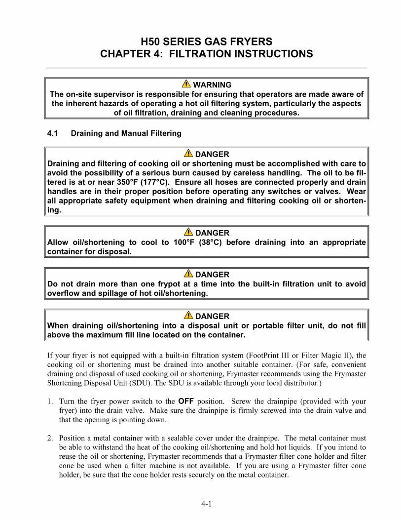
PREPARING THE FILTER UNIT FOR USE
1. Pull the filter unit from the cabinet, open the cover, remove the crumb tray, and remove the pa-per hold-down ring.
4-3
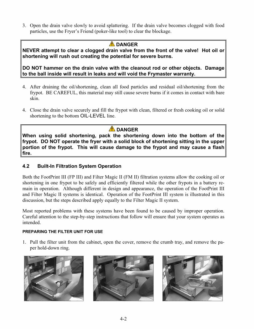
2. Remove used filter paper if present, and clean the pan as necessary. Verify that the metal filterscreen is in the bottom of the pan, and then lay a clean sheet of filter paper over the top of thepan, overlapping on all sides.
3. Position the hold-down ring over the filter paper and lower the ring into the pan, allowing thepaper to fold up around the ring as it is pushed to the bottom of the pan.
4. Sprinkle filter powder over the filter paper. (For powder quantity, see the filter powdermanufacturer’s instructions.) Replace the crumb tray in the filter pan and close the cover.
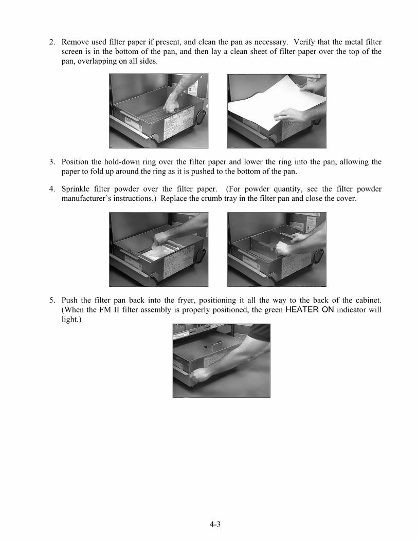
5. Push the filter pan back into the fryer, positioning it all the way to the back of the cabinet.(When the FM II filter assembly is properly positioned, the green HEATER ON indicator willlight.)

4-4
OPERATION OF THE FILTER UNIT
CAUTIONNever operate the filter unit unless the cooking oil in the fryers has been brought upto cooking temperature.
1. To filter the cooking oil, turn the fryerpower OFF, then open the drain valve onthe fryer you have selected to be filtered.If necessary, use the Fryer's Friend steelrod to clear the drain from inside thefrypot.
DANGERNEVER attempt to clear a clogged drain valve from the front of the valve! Hot oil orshortening will rush out creating the potential for severe burns.
DO NOT hammer on the drain valve with the cleanout rod or other objects. Damageto the ball inside will result in leaks and will void the Frymaster warranty.
DANGERDo not drain more than one frypot at a time into the built-in filtration unit to avoidoverflow and spillage of hot oil/shortening.
2. When the frypot is empty, use a scouring tool to remove sediment on the sides of the frypot.
WARNINGWhen cleaning the inside of the frypot, avoid striking the high limit thermostat andtemperature probe or operating thermostat.
3. Snap the Power Shower into the frypot.
Push handle tothe right to open..

4-5
DANGERDO NOT operate the filter without the Power Shower in place unless unit is configured with arear flush option. Hot oil will spray out of the fryer and may cause injury.
4. After all oil has drained from the pot, pushthe filter handle down and to the rear tostart the pump and begin the filteringprocess. (For units equipped with a rear-flush option, position the control lever toeither the Power Shower or Rear Flushposition.) There may be a slight delaybefore the pump activates.
5. After the oil is filtered, close the drainvalve and allow the fryer to refill. Let thefilter run 10 to 12 seconds after bubblesappear in the oil to clear the lines andprevent hardening of shortening in thelines.
WARNINGThe filter pump is equipped with a manual reset switch in case the filter motor overheats oran electrical fault occurs. If this switch trips, turn off power to the filter system and allow thepump motor to cool 20 minutes before attempting to reset the switch.
Push filterhandle down and
to the rear.
Push drain handleto the left to close.
4-6
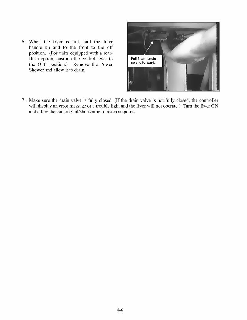
6. When the fryer is full, pull the filterhandle up and to the front to the offposition. (For units equipped with a rear-flush option, position the control lever tothe OFF position.) Remove the PowerShower and allow it to drain.
7. Make sure the drain valve is fully closed. (If the drain valve is not fully closed, the controllerwill display an error message or a trouble light and the fryer will not operate.) Turn the fryer ONand allow the cooking oil/shortening to reach setpoint.
Pull filter handleup and forward.

5-1
H50 SERIES GAS FRYERSCHAPTER 5: PREVENTIVE MAINTENANCE
5.1 Fryer Preventive Maintenance Checks and Service
DAILY CHECKS AND SERVICE
Inspect Fryer and Accessories for Damage
Look for loose or frayed wires and cords, leaks, foreign material in frypot or inside cabinet, and anyother indications that the fryer and accessories are not ready and safe for operation.
Clean Fryer Cabinet Inside and Out
Clean inside the fryer cabinet with dry, clean cloth. Wipe all accessible metal surfaces and compo-nents to remove accumulations of oil or shortening and dust.
Clean the outside of the fryer cabinet with a clean, damp cloth soaked with dishwashing detergent,removing oil/shortening, dust, and lint from the fryer cabinet.
DANGERNever attempt to clean fryer during the cooking process or when the frypot is filledwith hot oil/shortening. If water comes in contact with oil/shortening heated tocooking temperature, it can cause the oil/shortening to splatter and severely burnnearby personnel.
WEEKLY CHECKS AND SERVICE
Drain and Clean Frypot
During normal usage of your fryer, a deposit of carbonized cooking oil or shortening will graduallyform on the inside of the frypot. This deposit must be periodically removed to maintain your fryer’sefficiency.
DANGERAllow oil/shortening to cool to 100ºF (38ºC) or lower before draining to anappropriate container for disposal.
If your fryer is not equipped with a built-in filtration system, the cooking oil or shortening must bedrained into another suitable container. (For safe, convenient draining and disposal of used cookingoil or shortening, Frymaster recommends using our Shortening Disposal Unit (SDU). The SDU isavailable through your local distributor.)
1. Place the fryer power switch in the OFF position. Screw the drainpipe (provided with yourfryer) into the drain valve. Make sure the drainpipe is firmly screwed into the drain valve andthat the opening is pointing down.

5-2
2. Position a Shortening Disposal Unit (SDU) or a metal stock pot with a sealable cover under thedrainpipe. (The pot must be able to withstand the heat of the cooking oil/shortening and hold hotliquids.) If you intend to reuse the oil or shortening, Frymaster recommends that our filter coneholder and filter cone be used when a filter machine is not available. If you are using aFrymaster filter cone holder, be sure that the cone holder rests securely on the SDU or pot.
3. Open the drain valve slowly to avoid splattering. If the drain valve becomes clogged with foodparticles, use the Fryer’s Friend cleanout rod to clear the blockage.
DANGERDO NOT insert the cleanout rod into the drain from the front to unclog the valve. Hotoil/shortening will rush out, creating an extreme hazard.
DO NOT hammer on the drain valve. This will damage the drain valve ball andprevent the valve from sealing securely, resulting in a leaky valve.
4. After draining the oil/shortening, clean all food particles and residual oil/shortening from thefrypot. BE CAREFUL, this material may still cause severe burns if it comes in contact with bareskin.
5. Close the drain valve securely and fill the frypot with a solution of automatic dishwasherdetergent and water to the bottom OIL-LEVEL line. (Frymaster recommends the use ofFrymaster Boil-Out Solution, available through your local distributor, for best results.)
6. Set the thermostat to 195ºF (91ºC) or program the computer for Boil-Out (see separate Frymas-ter Fryer Controllers User’s Manual) and simmer the solution for 1 hour.
WARNINGNever leave the fryer unattended during this process. If the solution overflows,press the ON/OFF switch to the OFF position immediately.
7. After the solution has simmered for 1 hour, press the ON/OFF switch to the OFF position andallow the solution to cool.
8. Drain the solution into a suitable container (NOT the built-in filtration system filter pan orthe Shortening Disposal Unit) and thoroughly wipe the frypot with a clean towel.
9. Close the drain valve and fill the frypot with clean, cold water and drain into a suitable container(NOT the built-in filtration system filter pan or the Shortening Disposal Unit). Repeat therinse process again, and then wipe frypot with a clean, dry towel.
DANGEREnsure that the frypot is completely free of water before filling with cooking oil orshortening. When the oil or shortening is heated to cooking temperature, water inthe frypot will cause splattering.Clean Detachable Parts and Accessories
5-3
As with the frypot, a deposit of carbonized oil/shortening will accumulate on detachable parts andaccessories such as baskets, sediment trays, or fish plates
Wipe all detachable parts and accessories with a clean cloth dampened with a detergent solution.Rinse and thoroughly dry each part.
WARNINGUse a commercial-grade cleaner formulated to effectively clean and sanitize food-contactsurfaces. Read the directions for use and precautionary statements before use. Particularattention must be paid to the concentration of cleaner and the length of time the cleanerremains on the food-contact surfaces.
MONTHLY CHECKS AND SERVICE
Check Calibration of Analog Controller Thermostat Control Knob
(This check applies only to units equipped with Analog Controllers)
1. Insert a good-grade thermometer or pyrometer probe into the oil/shortening, with the end touch-ing the fryer temperature-sensing probe and set the thermostat knob to frying temperature.
2. After the set temperature is reached, let the burner cycle on and off automatically three times toallow the cooking oil/shortening temperature to become uniform. If necessary, stir to get allshortening in the bottom of the frypot melted.
3. When the burner starts for the fourth time, the thermometer/pyrometer reading should be within± 5ºF (2ºC) of the thermostat knob setting. If it is not, calibrate as follows:
a. Loosen setscrew in thermostat control knob until the knob will rotate freely on its shaft.
b. Rotate the knob until the index line on the knob is aligned with the marking that correspondsto the thermometer or pyrometer reading.
c. Hold the knob and carefully tighten the setscrew.
d. Recheck the thermometer/pyrometer reading against the thermostat knob setting the nexttime the burner lights.
e. Repeat steps 4.a. through 4.d. until the thermometer/pyrometer reading and knob settingagree within ± 5ºF (2ºC). If calibration cannot be obtained for any reason, call a FactoryAuthorized Service Center for assistance.
5. Remove the thermometer or pyrometer.
Check Computer Magic III Set Point Accuracy
(This check applies only to units equipped with Computer Magic III Controllers.)
1. Insert a good-grade thermometer or pyrometer probe into the oil/shortening, with the end touch-ing the fryer temperature-sensing probe.

5-4
2. When the computer display shows a series of four dashes “----” with no dot between the first andsecond dashes (indicating that the frypot contents are within the cooking range), press the switch once to display the temperature of the cooking oil or shortening as sensed by thetemperature probe.
3. Press the switch twice to display the set point.
4. Note the temperature on the thermometer or pyrometer. All three readings should be within± 5ºF (2ºC) of each other. If not, contact a Factory Authorized Service Center for assistance.
QUARTERLY CHECKS AND SERVICE
Clean Combustion Air Blower Assembly
A sheet metal shield or shield assembly prevents inadvertent access to the blower assembly. Thespecific design varies depending upon the particular configuration of the fryer and the country forwhich manufactured, but in all cases the shield is attached to the cabinet framing by sheet metalscrews. Remove the screws that secure the shield or shield assembly to the cabinet framing and pullthe shield out of the fryer to expose the combustion air blower assembly.
1. Disconnect the blower wiring harness and remove the four blower mounting nuts.
2. Remove the three fasteners that secure the blower motor assembly to the blower housing, andseparate the two components.
Wiring connectionBlower
assemblymounting nuts
5-5
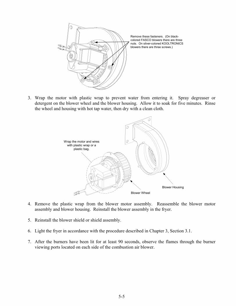
Remove these fasteners. (On black-colored FASCO blowers there are threenuts. On silver-colored KOOLTRONICSblowers there are three screws.)
3. Wrap the motor with plastic wrap to prevent water from entering it. Spray degreaser ordetergent on the blower wheel and the blower housing. Allow it to soak for five minutes. Rinsethe wheel and housing with hot tap water, then dry with a clean cloth.
Blower Housing
Blower Wheel
Wrap the motor and wireswith plastic wrap or a
plastic bag.
4. Remove the plastic wrap from the blower motor assembly. Reassemble the blower motorassembly and blower housing. Reinstall the blower assembly in the fryer.
5. Reinstall the blower shield or shield assembly.
6. Light the fryer in accordance with the procedure described in Chapter 3, Section 3.1.
7. After the burners have been lit for at least 90 seconds, observe the flames through the burnerviewing ports located on each side of the combustion air blower.
5-6
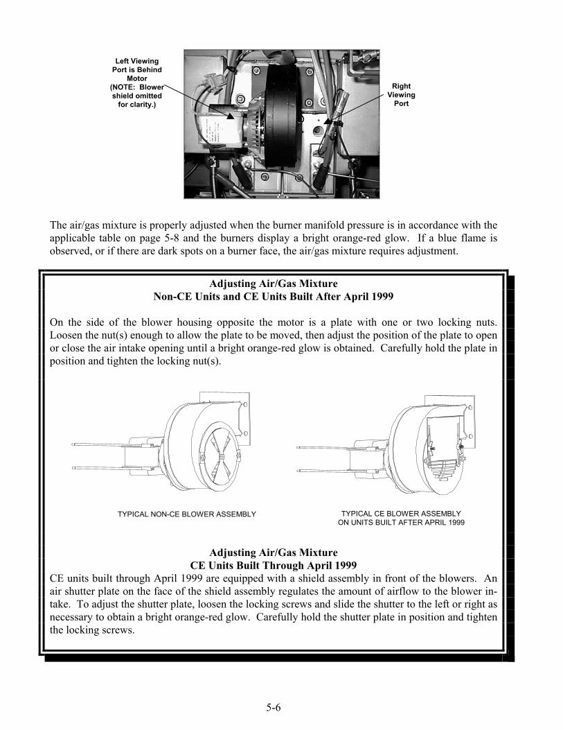
The air/gas mixture is properly adjusted when the burner manifold pressure is in accordance with theapplicable table on page 5-8 and the burners display a bright orange-red glow. If a blue flame isobserved, or if there are dark spots on a burner face, the air/gas mixture requires adjustment.
Adjusting Air/Gas MixtureNon-CE Units and CE Units Built After April 1999
On the side of the blower housing opposite the motor is a plate with one or two locking nuts.Loosen the nut(s) enough to allow the plate to be moved, then adjust the position of the plate to openor close the air intake opening until a bright orange-red glow is obtained. Carefully hold the plate inposition and tighten the locking nut(s).
TYPICAL NON-CE BLOWER ASSEMBLY TYPICAL CE BLOWER ASSEMBLYON UNITS BUILT AFTER APRIL 1999
Adjusting Air/Gas MixtureCE Units Built Through April 1999
CE units built through April 1999 are equipped with a shield assembly in front of the blowers. Anair shutter plate on the face of the shield assembly regulates the amount of airflow to the blower in-take. To adjust the shutter plate, loosen the locking screws and slide the shutter to the left or right asnecessary to obtain a bright orange-red glow. Carefully hold the shutter plate in position and tightenthe locking screws.
RightViewing
Port
Left ViewingPort is Behind
Motor(NOTE: Blowershield omitted
for clarity.)

5-7
TYPICAL CE BLOWER SHIELD ASSEMBLYON UNITS BUILT THROUGH APRIL 1999
SEMI-ANNUAL CHECKS AND SERVICE
Clean Gas Valve Vent Tube
NOTE: This procedure is not required for fryers configured for export to CEcountries.
1. Set the fryer power switch and the gas valve to the OFF position.
2. Carefully unscrew the vent tube from the gas valve. NOTE: The vent tube may be straightenedfor ease in removal.
3. Pass a piece of ordinary binding wire (.052 inch diameter) through the tube to remove anyobstruction.
4. Remove the wire and blow through the tube to ensure it is clear.
5. Reinstall the tube and bend it so that the opening is pointing downward.
Check Burner Manifold Pressure
DANGERThis task should be performed by qualified service personnel only. Contact yourFASC to arrange this service.

5-8
5.2 Built-in Filtration System Preventive Maintenance Checks and Service
WARNINGNever operate the filter system without cooking oil/shortening in the system.
WARNINGNever use the filter pan to transport old cooking oil/shortening to the disposal area.
WARNINGNever drain water into the filter pan. Water will damage the filter pump.
There are no periodic preventive maintenance checks and services required for your FootPrint III orFilter Magic II Filtration Systems other than daily cleaning of the filter pan with a solution of hotwater and detergent.
If you notice that the system is pumping slowly or not at all, verify that the filter pan screen is on thebottom of the filter pan, with the paper on top of the screen. Verify that the o-ring(s) are present andin good condition. For FootPrint III units, there is a single o-ring located on the bottom of the filterpan. For Filter Magic II systems, there is an o-ring on the bottom of the pan and two on the fitting atthe inside back of the cabinet.
Immediately after each use, drain the Power Shower completely. If oil is leaking at the point wherethe Power Shower plugs into the frypot, verify that the o-ring and gasket on the connection fittingare present and in good condition. If you suspect blockage, unscrew the clean-out plugs at eachcorner of the frame. Place the frame in a pan of hot water for several minutes to melt anyaccumulation of solidified oil/shortening. Use a long, narrow bottlebrush with hot water anddetergent to clean inside the tubes. If necessary, insert a straightened paper clip or similarly sizedwire into the holes in the frame to remove any solidified shortening or other blockages. Rinse withhot water, dry thoroughly, and reinstall the plugs before using.
CLEAN-OUT PLUGS
GASKETO-RING
DANGERFailure to reinstall the clean-out plugs in the Power Shower will cause hotoil/shortening to spray out of the frypot during the filtering process, creating anextreme burn hazard to personnel.
5-9
5.3 Annual/Periodic System Inspection
This appliance should be inspected and adjusted periodically by qualified service personnel aspart of a regular kitchen maintenance program.
Frymaster recommends that this appliance be inspected at least annually by a FactoryAuthorized Service Technician as follows:
Fryer
• Inspect the cabinet inside and out, front and rear for excessive oil build-up and/or oil migration.
• Verify that the flue opening is not obstructed by debris or accumulations of solidified oil orshortening.
• Verify that burners and associated components (i.e. gas valves, pilot assemblies, ignitors, etc.)are in good condition and functioning properly. Inspect all gas connections for leaks and verifythat all connections are properly tightened.
• Verify that the burner manifold pressure is in accordance with that specified on the appliance’srating plate.
• Verify that the temperature and high-limit probes are properly connected, tightened andfunctioning properly, and that probe guards are present and properly installed.
• Verify that component box components (i.e. computer/controller, transformers, relays, interfaceboards, etc.) are in good condition and free from oil migration build-up and other debris. Inspectthe component box wiring and verify that connections are tight and that wiring is in good condi-tion.
• Verify that all safety features (i.e. drain safety switches, reset switches, etc.) are present andfunctioning properly.
• Verify that the frypot/cookpot is in good condition and free of leaks and that the frypot/cookpotinsulation is in serviceable condition.
• Verify that wiring harnesses and connections are tight and in good condition.
Built-In Filtration System
• Inspect all oil-return and drain lines for leaks and verify that all connections are tight.
• Inspect the filter pan for leaks and cleanliness. If there is a large accumulation of crumbs in thecrumb basket, advise the owner/operator that the crumb basket should be emptied into a fireproofcontainer and cleaned daily.
• Verify that all O-rings and seals (including those on the Power Shower and on the Filter Magicquick-disconnect fitting) are present and in good condition. Replace o-rings and seals if worn ordamaged.
5-10
• Check filtration system integrity as follows:
− With the filter pan empty, place each oil return handle, one at a time, in the ON position.Verify that the pump activates and that bubbles appear in the cooking oil/shortening (or thatgurgling is heard from the Power Shower port) of the associated frypot..
− Close all oil return valves (i.e., place all oil return handles in the OFF position). Verifyproper functioning of each oil return valve by activating the filter pump using the lever onone of the oil return handle microswitches. No air bubbles should be visible in any frypot (orno gurgling should be heard from the Power Shower ports).
− Verify that the filter pan is properly prepared for filtering, then drain a frypot of oil heated to350°F (177°C) into the filter pan and close the frypot drain valve. Place the oil return handlein the ON position. Allow all cooking oil/shortening to return to the frypot (indicated bybubbles in the cooking oil/shortening or, on units with Power Showers, cessation of oil flowfrom the Power Shower). Return the oil return handle to the OFF position. The frypot shouldhave refilled in no more than 2 minutes and 30 seconds.
6-1
H50 SERIES GAS FRYERSCHAPTER 6: OPERATOR TROUBLESHOOTING
6.1 Introduction
This chapter provides an easy reference guide to some of the common problems that may occurduring the operation of your equipment. The troubleshooting guides that follow are intended to helpyou correct, or at least accurately diagnose, problems with your equipment. Although the chaptercovers the most common problems reported, you may encounter problems that are not covered. Insuch instances, the Frymaster Technical Services staff will make every effort to help you identifyand resolve the problem.
When troubleshooting a problem, always use a process of elimination starting with the simplestsolution and working through to the most complex. Most importantly, always try to establish a clearidea of why a problem has occurred. Part of your corrective action involves taking steps to ensurethat it doesn’t happen again. If a controller malfunctions because of a poor connection, check allother connections while you’re at it. If a fuse continues to blow, find out why. Always keep in mindthat failure of a small component may often be indicative of potential failure or incorrect functioningof a more important component or system.
Some of the troubleshooting actions recommended in this chapter involve removing suspectcomponents and substituting components that are known to be good. Whenever this in indicated,refer to Sections 6.7 for specific instructions
If you are in doubt as to the proper action to take, do not hesitate to call the Frymaster TechnicalService Department or your local Frymaster Factory Authorized Service Center for assistance.
Before calling a servicer or the Frymaster HOTLINE (1-800-551-8633):• Verify that electrical cords are plugged in and that circuit breakers are on.• Verify that gas line quick-disconnects are properly connected.• Verify that any gas line cutoff valves are open.• Verify that frypot drain valves are fully closed.
DANGERHot cooking oil/shortening will cause severe burns. Never attempt to this appliancewhen filled with hot cooking oil/shortening or to transfer hot cooking oil/shortening fromone container to another.
DANGERThis equipment should be unplugged when servicing, except when electrical circuittests are required. Use extreme care when performing such tests.
This appliance may have more than one electrical power supply connection point.Disconnect all power cords before servicing.
Inspection, testing, and repair of electrical components should be performed by anauthorized service agent only.
6-2
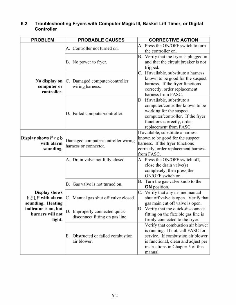
6.2 Troubleshooting Fryers with Computer Magic III, Basket Lift Timer, or DigitalController
PROBLEM PROBABLE CAUSES CORRECTIVE ACTION
A. Controller not turned on. A. Press the ON/OFF switch to turnthe controller on.
B. No power to fryer.B. Verify that the fryer is plugged in
and that the circuit breaker is nottripped.
C. Damaged computer/controllerwiring harness.
C. If available, substitute a harnessknown to be good for the suspectharness. If the fryer functionscorrectly, order replacementharness from FASC.
No display oncomputer or
controller.
D. Failed computer/controller.
D. If available, substitute acomputer/controller known to beworking for the suspectcomputer/controller. If the fryerfunctions correctly, orderreplacement from FASC.
Display shows with alarm
sounding.
Damaged computer/controller wiringharness or connector.
If available, substitute a harnessknown to be good for the suspectharness. If the fryer functionscorrectly, order replacement harnessfrom FASC.
A. Drain valve not fully closed. A. Press the ON/OFF switch off,close the drain valve(s)completely, then press theON/OFF switch on.
B. Gas valve is not turned on. B. Turn the gas valve knob to theON position.
C. Manual gas shut off valve closed.C. Verify that any in-line manual
shut off valve is open. Verify thatgas main cut off valve is open.
D. Improperly connected quick-disconnect fitting on gas line.
D. Verify that the quick-disconnectfitting on the flexible gas line isfirmly connected to the fryer.
Display shows with alarm
sounding. Heatingindicator is on, but
burners will notlight.
E. Obstructed or failed combustionair blower.
Verify that combustion air bloweris running. If not, call FASC forservice. If combustion air bloweris functional, clean and adjust perinstructions in Chapter 5 of thismanual.
6-3
PROBLEM PROBABLE CAUSES CORRECTIVE ACTION
A. Failed computer/controller.
A. If available, substitute acomputer/controller known to beworking for the suspectcomputer/controller. If the fryerfunctions correctly, orderreplacement from FASC.
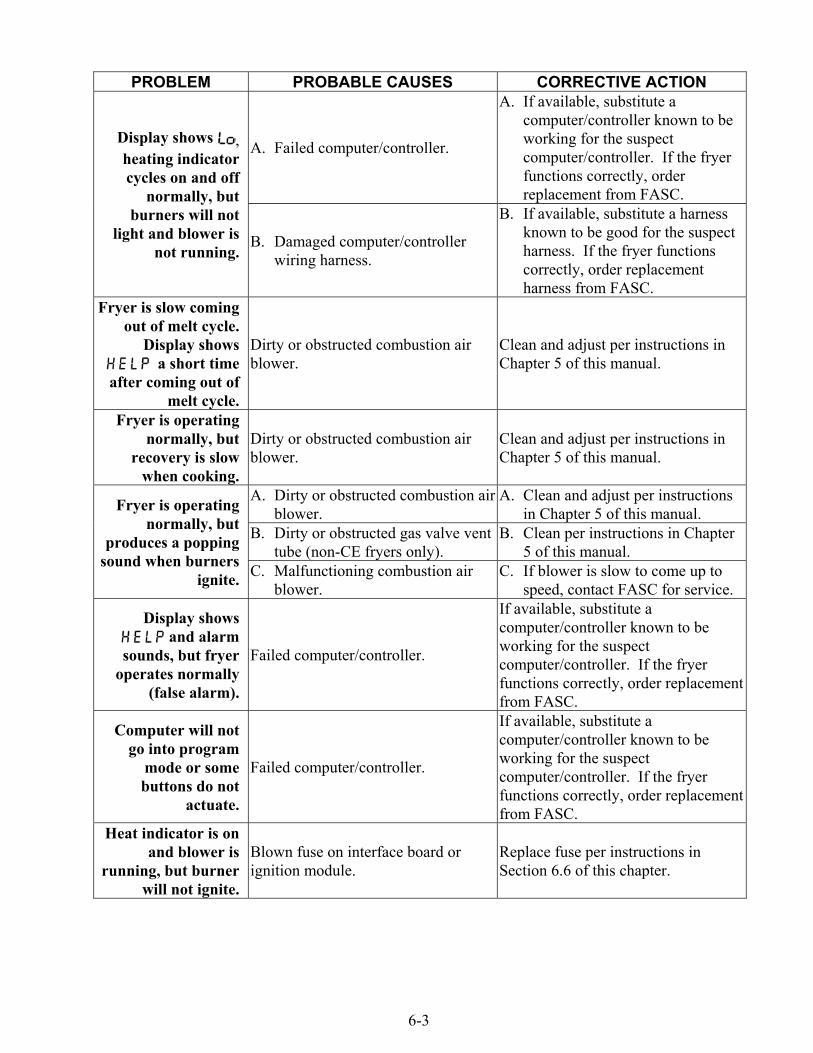
Display shows ,heating indicatorcycles on and off
normally, butburners will not
light and blower isnot running.
B. Damaged computer/controllerwiring harness.
B. If available, substitute a harnessknown to be good for the suspectharness. If the fryer functionscorrectly, order replacementharness from FASC.
Fryer is slow comingout of melt cycle.
Display shows a short time
after coming out ofmelt cycle.
Dirty or obstructed combustion airblower.
Clean and adjust per instructions inChapter 5 of this manual.
Fryer is operatingnormally, but
recovery is slowwhen cooking.
Dirty or obstructed combustion airblower.
Clean and adjust per instructions inChapter 5 of this manual.
A. Dirty or obstructed combustion airblower.
A. Clean and adjust per instructionsin Chapter 5 of this manual.
B. Dirty or obstructed gas valve venttube (non-CE fryers only).
B. Clean per instructions in Chapter5 of this manual.
Fryer is operatingnormally, but
produces a poppingsound when burners
ignite. C. Malfunctioning combustion airblower.
C. If blower is slow to come up tospeed, contact FASC for service.
Display shows and alarm
sounds, but fryeroperates normally
(false alarm).
Failed computer/controller.
If available, substitute acomputer/controller known to beworking for the suspectcomputer/controller. If the fryerfunctions correctly, order replacementfrom FASC.
Computer will notgo into program
mode or somebuttons do not
actuate.
Failed computer/controller.
If available, substitute acomputer/controller known to beworking for the suspectcomputer/controller. If the fryerfunctions correctly, order replacementfrom FASC.
Heat indicator is onand blower is
running, but burnerwill not ignite.
Blown fuse on interface board orignition module.
Replace fuse per instructions inSection 6.6 of this chapter.

6-4
PROBLEM PROBABLE CAUSES CORRECTIVE ACTION
Heat indicator offupon initial startup.
Display shows or with alarm
sounding.
Failed computer/controller.
If available, substitute acomputer/controller known to beworking for the suspectcomputer/controller. If the fryerfunctions correctly, order replacementfrom FASC.
6.3 Troubleshooting Fryers with Solid State (Analog) Controller
PROBLEM PROBABLE CAUSES CORRECTIVE ACTION
A. No power to fryer.A. Verify that the fryer is plugged in
and that the circuit breaker is nottripped.
B. Damaged controller wiringharness.
B. If available, substitute a harnessknown to be good for the suspectharness. If the fryer functionscorrectly, order replacementharness from FASC.
Power switch ON, nolights on controller,fryer does not heat.
C. Failed controller.
C. If available, substitute a controllerknown to be working for thesuspect controller. If the fryerfunctions correctly, orderreplacement from FASC.
Power light ON,trouble light ON,
heating mode lightOFF.
Damaged controller wiring harness.
If available, substitute a harnessknown to be good for the suspectharness. If the fryer functionscorrectly, order replacement harnessfrom FASC.
A. Drain valve not fully closed.
A. Press the ON/OFF switch off,close the drain valve(s)completely, then press theON/OFF switch on.
B. Gas valve is not turned on. B. Turn the gas valve knob to theON position.
C. Manual gas shut off valve closed.C. Verify that any in-line manual
shut off valve is open. Verify thatgas main cut off valve is open.
D. Improperly connected quick-disconnect fitting on gas line.
D. Verify that the quick-disconnectfitting on the flexible gas line isfirmly connected to the fryer.
Power light ON,trouble light ON,
heating mode lightON. Burners do not
ignite.
E. Obstructed or failed combustionair blower.
E. Verify that combustion air bloweris running. If not, call FASC forservice. If combustion air bloweris functional, clean and adjust perinstructions in Chapter 5 of thismanual.
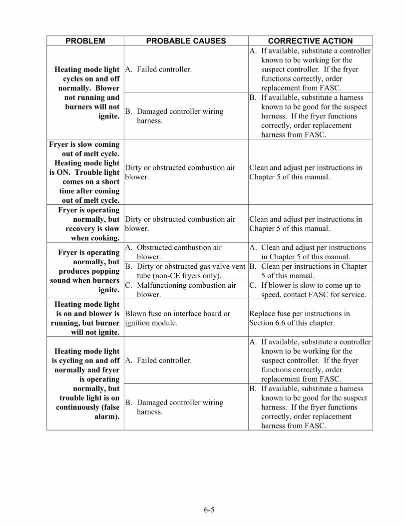
6-5
PROBLEM PROBABLE CAUSES CORRECTIVE ACTION
A. Failed controller.
A. If available, substitute a controllerknown to be working for thesuspect controller. If the fryerfunctions correctly, orderreplacement from FASC.
Heating mode lightcycles on and off
normally. Blowernot running andburners will not
ignite. B. Damaged controller wiringharness.
B. If available, substitute a harnessknown to be good for the suspectharness. If the fryer functionscorrectly, order replacementharness from FASC.
Fryer is slow comingout of melt cycle.
Heating mode lightis ON. Trouble light
comes on a shorttime after comingout of melt cycle.
Dirty or obstructed combustion airblower.
Clean and adjust per instructions inChapter 5 of this manual.
Fryer is operatingnormally, but
recovery is slowwhen cooking.
Dirty or obstructed combustion airblower.
Clean and adjust per instructions inChapter 5 of this manual.
A. Obstructed combustion airblower.
A. Clean and adjust per instructionsin Chapter 5 of this manual.
B. Dirty or obstructed gas valve venttube (non-CE fryers only).
B. Clean per instructions in Chapter5 of this manual.
Fryer is operatingnormally, but
produces poppingsound when burners
ignite. C. Malfunctioning combustion airblower.
C. If blower is slow to come up tospeed, contact FASC for service.
Heating mode lightis on and blower is
running, but burnerwill not ignite.
Blown fuse on interface board orignition module.
Replace fuse per instructions inSection 6.6 of this chapter.
A. Failed controller.
A. If available, substitute a controllerknown to be working for thesuspect controller. If the fryerfunctions correctly, orderreplacement from FASC.
Heating mode lightis cycling on and offnormally and fryer
is operatingnormally, but
trouble light is oncontinuously (false
alarm).
B. Damaged controller wiringharness.
B. If available, substitute a harnessknown to be good for the suspectharness. If the fryer functionscorrectly, order replacementharness from FASC.
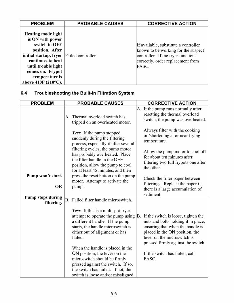
6-6
PROBLEM PROBABLE CAUSES CORRECTIVE ACTION
Heating mode lightis ON with power
switch in OFFposition. After
initial startup, fryercontinues to heat
until trouble lightcomes on. Frypot
temperature isabove 410F (210°C).
Failed controller.
If available, substitute a controllerknown to be working for the suspectcontroller. If the fryer functionscorrectly, order replacement fromFASC.
6.4 Troubleshooting the Built-in Filtration System
PROBLEM PROBABLE CAUSES CORRECTIVE ACTION
A. Thermal overload switch hastripped on an overheated motor.
Test: If the pump stoppedsuddenly during the filteringprocess, especially if after severalfiltering cycles, the pump motorhas probably overheated. Placethe filter handle in the OFFposition, allow the pump to coolfor at least 45 minutes, and thenpress the reset button on the pumpmotor. Attempt to activate thepump.
A. If the pump runs normally afterresetting the thermal overloadswitch, the pump was overheated.
Always filter with the cookingoil/shortening at or near fryingtemperature.
Allow the pump motor to cool offfor about ten minutes afterfiltering two full frypots one afterthe other.
Check the filter paper betweenfilterings. Replace the paper ifthere is a large accumulation ofsediment.
Pump won’t start.
OR
Pump stops duringfiltering. B. Failed filter handle microswitch.
Test: If this is a multi-pot fryer,attempt to operate the pump usinga different handle. If the pumpstarts, the handle microswitch iseither out of alignment or hasfailed.
When the handle is placed in theON position, the lever on themicroswitch should be firmlypressed against the switch. If so,the switch has failed. If not, theswitch is loose and/or misaligned.
B. If the switch is loose, tighten thenuts and bolts holding it in place,ensuring that when the handle isplaced in the ON position, thelever on the microswitch ispressed firmly against the switch.
If the switch has failed, callFASC.

6-7
PROBLEM PROBABLE CAUSES CORRECTIVE ACTION
(Continued fromprevious page.)
C. Pump blockage.
Test: Close the drain valve. Placethe filter handle in the OFFposition, allow the pump to coolfor at least 45 minutes, and thenpress the reset button on the pumpmotor. Pull the filter pan from theunit and then activate the pump.If the pump motor hums and thenstops, the pump is blocked.
C. Pump blockages are usuallycaused by sediment build-up inthe pump due to improperly sizedor installed filter paper and failureto use the crumb screen. CallFASC to have blockage cleared.
Ensure that filter paper is of theproper size and is installedproperly, and that the crumbscreen is used.
A. Cooking oil/shortening is too coldfor filtering.
A. To properly filter, the oil orshortening should be at or near350°F (177°C). At temperatureslower than this, the oil/shorteningbecomes too thick to pass throughthe filter medium easily, resultingin much slower oil return andeventual overheating of the filterpump motor. Ensure that thecooking oil/shortening is at ornear frying temperature beforedraining into filter pan.
B. Improperly installed or preparedfilter pan components.
Test: Close the drain valve.Move the filter handle to the OFFposition, pull the filter pan (andPower Shower, if so equipped)from the unit. Move the filterhandle to the ON position.
If a strong stream of air is beingpumped out of the oil return port(or the Power Shower port), theproblem is with the filter pancomponents.
B. Remove the oil from the filter panand replace the filter paper,ensuring that the filter screen is inplace under the paper.
C. If this does not correct theproblem, the filter tube suctiontube is probably blocked. Removethe blockage using a thin, flexiblewire. If unable to remove theblockage, call FASC.
Pump starts, but notransfer takes place
or the transfer isvery slow.
(Continued on following page.)
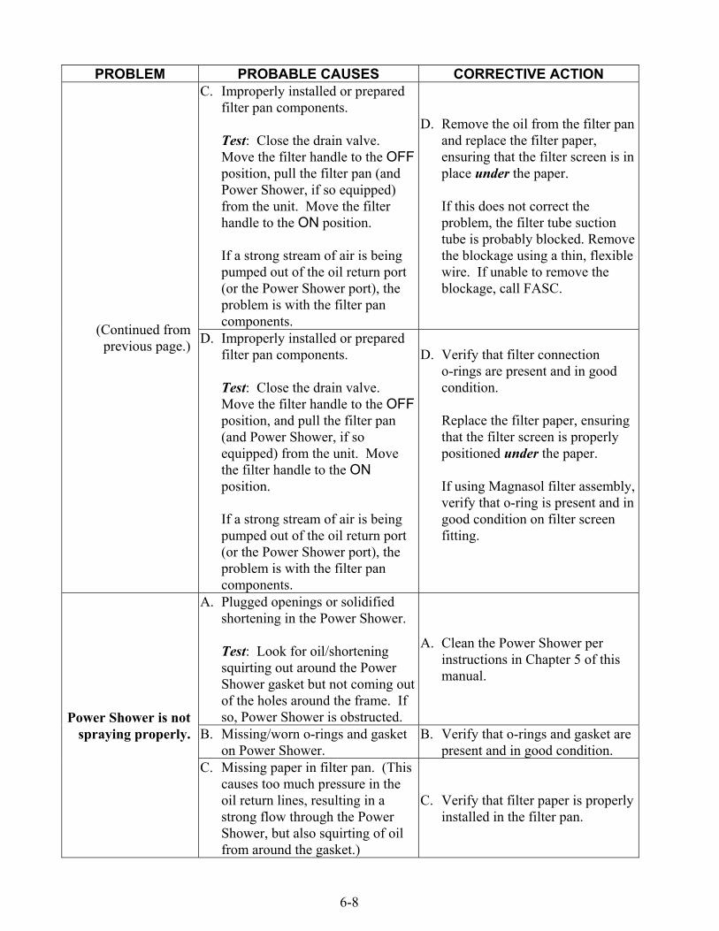
6-8
PROBLEM PROBABLE CAUSES CORRECTIVE ACTIONC. Improperly installed or prepared
filter pan components.
Test: Close the drain valve.Move the filter handle to the OFFposition, pull the filter pan (andPower Shower, if so equipped)from the unit. Move the filterhandle to the ON position.
If a strong stream of air is beingpumped out of the oil return port(or the Power Shower port), theproblem is with the filter pancomponents.
D. Remove the oil from the filter panand replace the filter paper,ensuring that the filter screen is inplace under the paper.
If this does not correct theproblem, the filter tube suctiontube is probably blocked. Removethe blockage using a thin, flexiblewire. If unable to remove theblockage, call FASC.
(Continued fromprevious page.) D. Improperly installed or prepared
filter pan components.
Test: Close the drain valve.Move the filter handle to the OFFposition, and pull the filter pan(and Power Shower, if soequipped) from the unit. Movethe filter handle to the ONposition.
If a strong stream of air is beingpumped out of the oil return port(or the Power Shower port), theproblem is with the filter pancomponents.
D. Verify that filter connectiono-rings are present and in goodcondition.
Replace the filter paper, ensuringthat the filter screen is properlypositioned under the paper.
If using Magnasol filter assembly,verify that o-ring is present and ingood condition on filter screenfitting.
A. Plugged openings or solidifiedshortening in the Power Shower.
Test: Look for oil/shorteningsquirting out around the PowerShower gasket but not coming outof the holes around the frame. Ifso, Power Shower is obstructed.
A. Clean the Power Shower perinstructions in Chapter 5 of thismanual.
B. Missing/worn o-rings and gasketon Power Shower.
B. Verify that o-rings and gasket arepresent and in good condition.
Power Shower is notspraying properly.
C. Missing paper in filter pan. (Thiscauses too much pressure in theoil return lines, resulting in astrong flow through the PowerShower, but also squirting of oilfrom around the gasket.)
C. Verify that filter paper is properlyinstalled in the filter pan.

6-9
6.5 Troubleshooting the Basket Lift
PROBLEM PROBABLE CAUSES CORRECTIVE ACTIONBasket lift
movement is jerkyand/or noisy.
Basket lift rods need lubrication.Lubricate basket lift rods withLubriplate™ or equivalent light whitegrease.
6.6 Replacing the Ignition Module Fuse
1. Disconnect the fryer from the electrical supply and remove the two screws in the upper cornersof the control panel. Swing the panel open from the top, allowing it to rest on its hinge tabs.
2. Locate the 3-amp ignition module fuse (refer to the illustration below), and using a fuse-puller,remove and replace it with a new fuse.
For units in which the ignitionmodule has no fuse, replace theupper fuse on the interface board.
Depending upon when the unit wasmanufactured, full vat units may have eitherone or two ignition modules. If there is onlyone ignition module, the fuse will be mountedon the interface board.
Dual vat units and some full vat units will havetwo ignigiton modules. Look for the fuse onthe left side of the module. If there are nofuses on the modules, the fuse will be on theinterface board.
Ignition Module
3. Close the panel and replace the control panel screws.
4. Reconnect the fryer to the electrical supply.
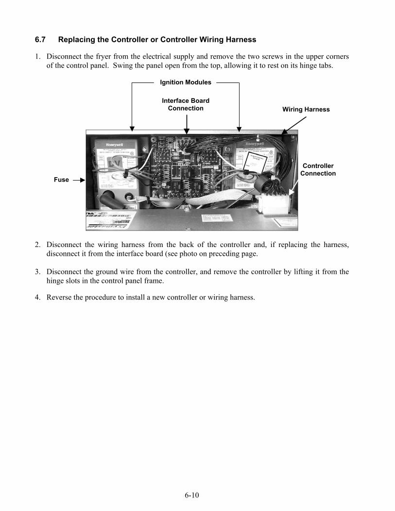
6-10
6.7 Replacing the Controller or Controller Wiring Harness
1. Disconnect the fryer from the electrical supply and remove the two screws in the upper cornersof the control panel. Swing the panel open from the top, allowing it to rest on its hinge tabs.
2. Disconnect the wiring harness from the back of the controller and, if replacing the harness,disconnect it from the interface board (see photo on preceding page.
3. Disconnect the ground wire from the controller, and remove the controller by lifting it from thehinge slots in the control panel frame.
4. Reverse the procedure to install a new controller or wiring harness.
Fuse
Interface BoardConnection
Ignition Modules
ControllerConnection
Wiring Harness

THIS PAGE INTENTIONALLY LEFT BLANK.

Frymaster, L.L.C., 8700 Line Avenue, PO Box 51000, Shreveport, Louisiana 71135-1000Shipping Address: 8700 Line Avenue, Shreveport, Louisiana 71106
TEL 1-318-865-1711 FAX (Parts) 1-318-219-7140 FAX (Tech Support) 1-318-219-7135
PRINTED IN THE UNITED STATESSERVICE HOTLINE
1-800-551-8633819-5000
APRIL 2004