INSTALLATION AND OPERATION MANUAL - Daikin · Sertifikat ą . 23 Piez ī mes * k ... déclare sous...
16
INSTALLATION AND OPERATION MANUAL FXLQ20P2VEB FXLQ25P2VEB FXLQ32P2VEB FXLQ40P2VEB FXLQ50P2VEB FXLQ63P2VEB FXNQ20P2VEB FXNQ25P2VEB FXNQ32P2VEB FXNQ40P2VEB FXNQ50P2VEB FXNQ63P2VEB System air conditioners
Transcript of INSTALLATION AND OPERATION MANUAL - Daikin · Sertifikat ą . 23 Piez ī mes * k ... déclare sous...

INSTALLATION ANDOPERATION MANUAL
FXLQ20P2VEBFXLQ25P2VEBFXLQ32P2VEBFXLQ40P2VEBFXLQ50P2VEBFXLQ63P2VEB
FXNQ20P2VEBFXNQ25P2VEBFXNQ32P2VEBFXNQ40P2VEBFXNQ50P2VEBFXNQ63P2VEB
System air conditioners

1
1
L N
IN/D OUT/DF1 F2 F1 F2
Control box
P1 P2
P1 P2
F1 F2 T1 T2 P1 P2 F1 F2 T1 T2 P1 P2 F1 F2 T1 T2 P1 P2 F1 F2 T1 T2
P1 P2P1 P2
2
53
L N L N L N L N4
3 4
L N L N
IN/D OUT/DF1 F2 F1 F2
Control box
L NL N
P1 P2
P1 P2 P1 P2 P1 P2 P1 P2
F1 F2 T1 T2 P1 P2 F1 F2 T1 T2 P1 P2 F1 F2 T1 T2 P1 P2 F1 F2 T1 T2
3
1
42L N L N L N L N
2
1
2
3 79
8 10
4
5
6
L N
IN/D OUT/DF1 F2 F1 F2
Control box
L N
P1 P2
P1 P2 P1 P2
F1 F2 T1 T2 P1 P2 F1 F2 T1 T2
3
IN/D OUT/DF1 F2 F1 F2
Control box
1 6 6
2L N L N
IN/D OUT/DF1 F2 F1 F2
Control box
4
1 2
34

Dai
kin
Ind
ust
ries
Cze
ch R
epu
blic
s.r
.o.
CE -
DECL
ARAT
ION-
OF-
CONF
ORM
ITY
CE -
KONF
ORM
ITÄT
SERK
LÄRU
NGCE
- DE
CLAR
ATIO
N-DE
-CO
NFO
RMIT
ECE
- CO
NFO
RMIT
EITS
VERK
LARI
NG
CE -
DECL
ARAC
ION-
DE-C
ONF
ORM
IDAD
CE -
DICH
IARA
ZIO
NE-D
I-CO
NFO
RMIT
ACE
- ∆H
ΛΩΣΗ
ΣΥΜΜ
ΟΡΦΩ
ΣΗΣ
CE -
DECL
ARAÇ
ÃO-D
E-CO
NFO
RMID
ADE
CE - ЗА
ЯВЛЕ
НИЕ-О-СО
ОТВЕ
ТСТВ
ИИCE
- O
VERE
NSST
EMM
ELSE
SERK
LÆRI
NGCE
- FÖ
RSÄK
RAN-
OM-Ö
VERE
NSTÄ
MM
ELSE
CE -
ERKL
ÆRI
NG O
M-S
AMSV
ARCE
- IL
MO
ITUS
-YHD
ENM
UKAI
SUUD
ESTA
CE -
PRO
HLÁŠ
ENÍ-O
-SHO
DĚ
CE -
IZJA
VA-O
-USK
LAĐE
NOST
ICE
- M
EGFE
LELŐ
SÉG
I-NYI
LATK
OZA
TCE
- DE
KLAR
ACJA
-ZG
ODN
OŚC
ICE
- DE
CLAR
AŢIE
-DE-
CONF
ORM
ITAT
E
CE -
IZJA
VA O
SKL
ADNO
STI
CE -
VAST
AVUS
DEKL
ARAT
SIO
ON
CE - ДЕ
КЛАР
АЦИЯ
-ЗА-ϹЪ
ОТВЕ
ТСТВ
ИЕ
CE -
ATIT
IKTI
ES-D
EKLA
RACI
JACE
- AT
BILS
TĪBAS
-DEK
LARĀ
CIJA
CE -
VYHL
ÁSEN
IE-Z
HODY
CE -
UYUM
LULU
K-Bİ
LDİRİSİ
01are
in co
nform
ity w
ith th
e foll
owing
stan
dard(
s) or
other
norm
ative
docu
ment(
s), pr
ovide
d tha
t thes
e are
used
in ac
corda
nce w
ith ou
rins
tructi
ons:
02de
r/den
folge
nden
Norm
(en) o
der e
inem
ande
ren N
ormdo
kume
nt od
er -do
kume
nten e
ntspri
cht/e
ntspre
chen
, unte
r der
Vorau
ssetz
ung,
daß s
ie ge
mäß u
nsere
n Anw
eisun
gen e
inges
etzt w
erden
:03
sont
confo
rmes
à la/
aux n
orme(s
) ou a
utre(s
) doc
umen
t(s) n
ormati
f(s), p
our a
utant
qu'ils
soien
t utilis
és co
nform
émen
t à no
s ins
tructi
ons:
04co
nform
de vo
lgend
e norm
(en) o
f één
of m
eer a
ndere
bind
ende
docu
mente
n zijn
, op v
oorw
aarde
dat z
e word
en ge
bruikt
overe
enko
mstig
onze
instr
uctie
s:05
están
en co
nform
idad c
on la
(s) si
guien
te(s)
norm
a(s) u
otro(
s) do
cume
nto(s)
norm
ativo
(s), s
iempre
que s
ean u
tilizad
os de
acue
rdo co
nnu
estra
s ins
trucc
iones
:06
sono
confo
rmi a
l(i) se
guen
te(i) s
tanda
rd(s)
o altro
(i) do
cume
nto(i)
a cara
ttere
norm
ativo
, a pa
tto ch
e ven
gano
usati
in co
nform
ità al
leno
stre i
struz
ioni:
07είναι σύμφ
ωνα μ
ε το(α
) ακόλουθο(α
) πρότυπ
ο(α) ή
άλλο
έγγραφ
ο(α) κανονισμ
ών, υπό
την π
ροϋπ
όθεση ό
τι χρησιμ
οποιο
ύνται σύμφω
ναμε
τις οδ
ηγίες
μας:
08es
tão e
m co
nform
idade
com
a(s) s
eguin
te(s)
norm
a(s) o
u ou
tro(s)
doc
umen
to(s)
norm
ativo
(s), d
esde
que
este
s seja
m uti
lizado
s de
acord
o com
as no
ssas
instr
uçõe
s:09
соответст
вуют
следую
щим ста
ндартам или други
м норм
ативны
м докум
ентам,
при условии их
использования
согла
сно наши
минструкциям:
10ov
erhold
er føl
gend
e sta
ndard
(er) e
ller a
ndet/
andre
retni
ngsg
ivend
e do
kume
nt(er)
, foru
dsat
at dis
se a
nven
des
i hen
hold
til vo
reins
truks
er:11
respe
ktive
utru
stning
är u
tförd
i öve
renss
tämme
lse m
ed o
ch fö
ljer f
öljan
de s
tanda
rd(er)
elle
r and
ra no
rmgiv
ande
dok
umen
t, un
der
föruts
ättnin
g att a
nvän
dning
sker
i öve
renss
tämme
lse m
ed vå
ra ins
trukti
oner:
12res
pekti
ve u
tstyr
er i o
veren
sstem
melse
med
følge
nde
stand
ard(er
) elle
r and
re no
rmgiv
ende
dok
umen
t(er),
unde
r foru
tssetn
ing a
v at
disse
bruk
es i h
enho
ld til
våre
instru
kser:
13va
staav
at se
uraav
ien s
tanda
rdien
ja m
uiden
ohje
ellist
en d
okum
enttie
n va
atimu
ksia
edell
yttäe
n, ett
ä nii
tä kä
ytetää
n oh
jeide
mme
muka
isesti
:14
za př
edpo
kladu
, že j
sou v
yužív
ány v
soula
du s
našim
i pok
yny,
odpo
vídají
násle
dujíc
ím no
rmám
nebo
norm
ativn
ím do
kume
ntům:
15u s
kladu
sa sl
ijedećim
stan
dardo
m(im
a) ili d
rugim
norm
ativn
im do
kume
ntom(
ima),
uz uv
jet da
se on
i kori
ste u
sklad
u s na
šim up
utama
:
16me
gfelel
nek a
z aláb
bi sz
abvá
ny(ok
)nak v
agy e
gyéb
irány
adó d
okum
entum
(ok)na
k, ha
azok
at elő
írás s
zerin
t has
ználj
ák:
17sp
ełniają
wymo
gi na
stępu
jącyc
h no
rm i
innyc
h do
kume
ntów
norm
aliza
cyjny
ch, p
od w
arunk
iem ż
e uż
ywan
e są
zgo
dnie
z na
szym
iins
trukc
jami:
18su
nt în
confo
rmita
te cu
urmă
torul
(urmă
toarel
e) sta
ndard
(e) sa
u alt(e
) doc
umen
t(e) n
ormati
v(e), c
u con
diţia
ca ac
estea
să fie
utiliz
ate în
confo
rmita
te cu
instr
ucţiu
nile n
oastr
e:19
sklad
ni z n
asled
njimi
stan
dardi
in dr
ugim
i norm
ativi,
pod p
ogoje
m, da
se up
orablj
ajo v
sklad
u z na
šimi n
avod
ili:20
on va
stavu
ses j
ärgmi
s(t)e
stand
ardi(te
)ga võ
i teist
e norm
atiivs
ete do
kume
ntide
ga, k
ui ne
id ka
sutat
akse
vasta
valt m
eie ju
hend
itele:
21съответст
ват на
следните
стандарти
или
други
норма
тивни
докум
енти
, при
условие
, че
се и
зползват
съгласно
наши
теинструкции
:22
atitin
ka že
miau
nurod
ytus s
tanda
rtus i
r (arba
) kitu
s norm
inius
doku
mentu
s su s
ąlyga
, kad
yra n
audo
jami p
agal
mūsų
nurod
ymus
:23
tad, ja
lietot
i atbi
lstoš
i ražo
tāja n
orādīj
umiem
, atbi
lst se
kojoš
iem st
anda
rtiem
un ci
tiem
norm
atīvie
m do
kume
ntiem
:24
sú v
zhod
e s na
sledo
vnou
(ými) n
ormou
(ami) a
lebo i
ným(
i) norm
atívn
ym(i)
doku
mento
m(am
i), za
pred
pokla
du, ž
e sa p
oužív
ajú v
súlad
esn
ašim
návo
dom:
25ürü
nün,
talim
atları
mıza
göre
kulla
nılma
sı koşu
luyla
aşağıda
ki sta
ndart
lar ve
norm
belirt
en be
lgeler
le uy
umlud
ur:
01Dir
ectiv
es, a
s ame
nded
.02
Direk
tiven
, gem
äß Än
derun
g.03
Direc
tives
, telle
s que
mod
ifiées
.04
Richtl
ijnen
, zoa
ls ge
amen
deerd
.05
Direc
tivas
, seg
ún lo
enme
ndad
o.06
Dirett
ive, c
ome d
a mod
ifica.
07Οδ
ηγιών, όπ
ως έχ
ουν τροπο
ποιηθ
εί.08
Direc
tivas
, con
forme
alter
ação
em.
09Ди
ректи
в со в
семи
поправками
.
10Dir
ektiv
er, m
ed se
nere
ændri
nger.
11Dir
ektiv,
med
föret
agna
ändri
ngar.
12Dir
ektiv
er, m
ed fo
retatt
e end
ringe
r.13
Direk
tiivejä
, sella
isina k
uin ne
ovat
muute
ttuina
.14
v plat
ném
zněn
í.15
Smjer
nice,
kako
je iz
mijen
jeno.
16irá
nyelv
(ek) é
s mód
osítá
saik
rende
lkezé
seit.
17z p
óźnie
jszym
i pop
rawka
mi.
18Dir
ectiv
elor, c
u ame
ndam
entel
e res
pecti
ve.
19Dir
ektiv
e z vs
emi s
preme
mbam
i.20
Direk
tiivid
koos
muu
datus
tega.
21Ди
ректи
ви, с
техните и
зменения
.22
Direk
tyvos
e su p
apild
ymais
.23
Direk
tīvās
un to
papil
dināju
mos.
24Sm
ernice
, v pl
atnom
znen
í.25
Deǧiş
tirilm
iş ha
lleriy
le Yö
netm
elikle
r.
01fol
lowing
the p
rovisio
ns of
:02
gemä
ß den
Vorsc
hrifte
n der:
03co
nform
émen
t aux
stipu
lation
s des
:04
overe
enko
mstig
de be
palin
gen v
an:
05sig
uiend
o las
disp
osicio
nes d
e:06
seco
ndo l
e pres
crizio
ni pe
r:07
με τή
ρηση
των δ
ιατάξεω
ν των
:08
de ac
ordo c
om o
previs
to em
:09
в соответствии с
положе
ниям
и:
10un
der ia
gttag
else a
f bes
temme
lserne
i:11
enlig
t villk
oren i
:12
gitt i
henh
old til
beste
mmels
ene i
:13
noud
attae
n mää
räyks
iä:14
za do
držen
í usta
nove
ní pře
dpisu
:15
prema
odred
bama
:16
köve
ti a(z)
:17
zgod
nie z
posta
nowie
niami
Dyre
ktyw:
18în
urma p
reved
erilor
:
19ob
upoš
tevan
ju do
ločb:
20va
stava
lt nõu
etele:
21следвайки к
лаузите н
а:22
laika
ntis n
uosta
tų, pa
teikia
mų:
23iev
ērojot
prasība
s, ka
s note
iktas
:24
održi
avajú
c usta
nove
nia:
25bu
nun k
oşull
arına
uygu
n olar
ak:
01No
te *
as se
t out
in <A
> and
judg
ed po
sitive
ly by <
B>
acco
rding
to th
e Cer
tifica
te<C
>.02
Hinw
eis *
wie in
<A> a
ufgefü
hrt un
d von
<B> p
ositiv
beurt
eilt
gemä
ß Zer
tifika
t<C>
.03
Rem
arqu
e *tel
que d
éfini
dans
<A> e
t éva
lué po
sitive
ment
par
<B> c
onfor
méme
nt au
Certi
ficat
<C>.
04Be
mer
k *zo
als ve
rmeld
in <A
> en p
ositie
f beo
ordee
ld do
or <B
> ove
reenk
omstig
Certi
ficaa
t<C>
.05
Nota
*co
mo se
estab
lece e
n <A>
y es
valor
ado
positi
vame
nte po
r <B>
de ac
uerdo
con e
l Ce
rtific
ado
<C>.
06No
ta *
deline
ato ne
l <A>
e giu
dicato
positi
vame
nte
da<B
> sec
ondo
il Cer
tifica
to<C
>.07
Σημείωση
*όπ
ως κα
θορίζ
εται στο
<A> κ
αι κρίνεται
θετικά α
πό
το <B
> σύμφω
να με
το Πι
στοπ
οιητικ
ό<C>
.08
Nota
*tal
como
estab
elecid
o em
<A> e
com
o pare
cer
positi
vo de
<B> d
e aco
rdo co
m o C
ertif
icado
<C>.
09Пр
имечание
*как
указа
но в
<A> и
в соотв
етстви
и сп
олож
ительны
м реш
ением <
B> со
гласно
Свид
етель
ству<
C>.
10Be
mæ
rk *
som
anfør
t i <A
> og p
ositiv
t vurd
eret a
f <B>
ih
enho
ld til C
ertif
ikat<
C>.
11In
form
atio
n *
enligt
<A> o
ch go
dkän
ts av
<B> e
nligt
Certi
fikat
et<C
>.12
Merk
*so
m de
t frem
komm
er i <
A> og
gjen
nom
positi
v be
dømm
else a
v <B>
ifølge
Serti
fikat
<C>.
13Hu
om *
jotka
on es
itetty
asiak
irjassa
<A> j
a jotk
a <B>
on
hyvä
ksyny
t Ser
tifika
atin
<C> m
ukais
esti.
14Po
znám
ka *
jak by
lo uv
eden
o v <A
> a po
zitivně z
jištěn
o <B>
vs
oulad
u sos
vědč
ením
<C>.
15Na
pom
ena *
kako
je izl
ožen
o u <A
> i po
zitivn
o ocije
njeno
od
stran
e <B>
prem
a Cer
tifika
tu<C
>.
16Me
gjeg
yzés
*a(z
) <A>
alap
ján, a
(z) <B
> iga
zolta
a me
gfelelé
st,
a(z) <
C>ta
núsít
vány
szeri
nt.17
Uwag
a *zg
odnie
z do
kume
ntacją
<A>
, poz
ytywn
ą opin
ią <B
> i Św
iadec
twem
<C>.
18No
tă *
aşa c
um es
te sta
bilit în
<A> ş
i apre
ciat p
ozitiv
de
<B> î
n con
formi
tate c
u Cer
tifica
tul<
C>.
19Op
omba
*ko
t je do
ločen
o v <A
> in o
dobre
no s
stran
i <B>
vs
kladu
sce
rtifik
atom
<C>.
20Mä
rkus
*na
gu on
näida
tud do
kume
ndis <
A> ja
heak
s kiid
etud <
B> jä
rgi va
stava
lt ser
tifika
adile
<C>.
21Забележк
а *как
то е и
злож
ено в
<A> и
оценено п
олож
ително
от <B
> съгл
асно
Сертиф
иката
<C>.
22Pa
stab
a *ka
ip nu
statyt
a <A>
ir ka
ip tei
giama
i nus
pręsta
<B>
paga
l Ser
tifika
tą<C
>.23
Piezīm
es *
kā no
rādīts
<A> u
n atbi
lstoši <
B> po
zitīva
jam
vērtē
jumam
saska
ņā ar
serti
fikātu
<C>.
24Po
znám
ka *
ako b
olo uv
eden
é v <A
> a po
zitívn
e ziste
né <B
> vs
úlade
s os
vedč
ením
<C>.
25No
t *<A
>’da b
elirtild
iği gib
i ve <C
>Se
rtifik
asına
göre
<B> t
arafın
dan o
lumlu
olarak
değe
rlend
irildiği
gibi.
<A
>D
AIK
IN.T
CF.
024E
19/
07-
20
12
<B
>T
ÜV
(N
B1
856)
<C
>05
102
6010
1
01 a
decla
res un
der it
s sole
resp
onsib
ility th
at the
air c
ondit
ioning
mod
els to
whic
h this
decla
ration
relat
es:
02 d
erklär
t auf
seine
allei
nige V
erantw
ortun
g daß
die M
odell
e der
Klima
gerät
e für
die di
ese E
rkläru
ng be
stimm
t ist:
03 f
décla
re so
us sa
seule
resp
onsa
bilité
que l
es ap
parei
ls d'a
ir con
dition
né vi
sés p
ar la
prése
nte dé
clarat
ion:
04 l
verkl
aart h
ierbij
op ei
gen e
xclus
ieve v
erantw
oorde
lijkhe
id da
t de a
ircon
dition
ing un
its w
aarop
deze
verkl
aring
betre
kking
heeft
:05
ede
clara
baja
su ún
ica re
spon
sabil
idad q
ue lo
s mod
elos d
e aire
acon
dicion
ado a
los c
uales
hace
refer
encia
la de
clarac
ión:
06 i
dichia
ra so
tto su
a res
pons
abilità
che i
cond
iziona
tori m
odell
o a cu
i è rif
erita
ques
ta dic
hiaraz
ione:
07 g
δηλώ
νει με
αποκλειστ
ική τη
ς ευθύνη ό
τι τα μ
οντέλ
α των
κλιμα
τιστικών
συσκευών
στα ο
ποία αναφ
έρετα
ι η παρούσα
δήλω
ση:
08 p
decla
ra so
b sua
exclu
siva r
espo
nsab
ilidad
e que
os m
odelo
s de a
r con
dicion
ado a
que e
sta de
claraç
ão se
refer
e:
09 u
заявляет, и
сключ
ительно
под с
вою о
тветст
венность,
что м
одели к
ондиционеров
возду
ха, к
которым
относится
насто
ящее
заявление:
10 q
erklæ
rer un
der e
nean
svar,
at kl
imaa
nlægm
odell
erne,
som
denn
e dek
larati
on ve
drører
:11
sde
klarer
ar i e
gens
kap a
v huv
udan
svari
g, att
luftk
ondit
ioneri
ngsm
odell
erna s
om be
rörs a
v den
na de
klarat
ion in
nebä
r att:
12 n
erklæ
rer et
fulls
tendig
ansv
ar for
at de
luftk
ondis
joneri
ngsm
odell
er so
m be
røres
av de
nne d
eklar
asjon
, inne
bærer
at:
13 j
ilmoit
taa yk
sinom
aan o
malla
vastu
ullaa
n, ett
ä täm
än ilm
oituk
sen t
arkoit
tamat
ilmas
tointi
laitte
iden m
allit:
14 c
prohla
šuje
ve sv
é plné
odpo
vědn
osti,
že m
odely
klim
atiza
ce, k
nimž
se to
to pro
hláše
ní vz
tahuje
:15
yizja
vljuje
pod i
sključiv
o vlas
titom
odgo
vorno
šću d
a su m
odeli
klim
a uređ
aja na
koje
se ov
a izja
va od
nosi:
16 h
teljes
felelős
sége
tuda
tában
kijel
enti,
hogy
a klí
mabe
rende
zés m
odell
ek, m
elyek
re e n
yilatko
zat v
onatk
ozik:
17 m
dekla
ruje n
a włas
ną i w
yłącz
ną od
powie
dzial
ność
, że m
odele
klim
atyza
torów
, któr
ych d
otycz
y nini
ejsza
dekla
racja:
18 r
decla
ră pe
prop
rie ră
spun
dere
că ap
aratel
e de a
er co
ndiţio
nat la
care
se re
feră a
ceas
tă de
claraţ
ie:19
oz v
so od
govo
rnostj
o izja
vlja, d
a so m
odeli
klim
atskih
napra
v, na
kater
e se i
zjava
nana
ša:
20 x
kinnit
ab om
a täie
likul
vastu
tusel,
et kä
esole
va de
klarat
sioon
i alla
kuulu
vad k
liimas
eadm
ete m
udeli
d:21
bдекларира н
а своя о
тговорност, ч
е моделите к
лима
тична и
нсталация, за
които с
е отнася т
ази д
екларация:
22 t
visišk
a sav
o atsa
komy
be sk
elbia,
kad o
ro ko
ndicio
navim
o prie
taisų
mod
eliai,
kurie
ms yr
a taik
oma š
i dek
larac
ija:
23 v
ar pil
nu at
bildīb
u apli
ecina
, ka tālā
k uzs
kaitīt
o mod
eļu ga
isa ko
ndicio
nētāj
i, uz k
uriem
attie
cas š
ī dek
larāc
ija:
24 k
vyhla
suje
na vl
astnú
zodp
oved
nosť,
že tie
to klim
atizačn
é mod
ely, n
a ktor
é sa v
zťahu
je tot
o vyh
lásen
ie:25
wtam
amen
kend
i soru
mlulu
ǧund
a olm
ak üz
ere bu
bildi
rinin
ilgili o
lduǧu
klim
a mod
elleri
nin aş
aǧıda
ki gib
i oldu
ǧunu
beya
n ede
r:
EN
6033
5-2-
40,
3P323721-1
Taka
yuki
Fuj
iiM
anag
ing
Dire
ctor
5th
of N
ovem
ber 2
012
01**
DICZ
*** is
autho
rised
to co
mpile
the T
echn
ical C
onstr
uctio
n File
.02
**DI
CZ***
hat d
ie Be
rechti
gung
die T
echn
ische
Kons
trukti
onsa
kte zu
samm
enzu
stelle
n.03
**DI
CZ***
est a
utoris
é à co
mpile
r le D
ossie
r de C
onstr
uctio
n Tec
hniqu
e.04
**DI
CZ***
is be
voeg
d om
het T
echn
isch C
onstr
uctie
doss
ier sa
men t
e stel
len.
05**
DICZ
*** es
tá au
toriza
do a
comp
ilar e
l Arch
ivo de
Con
struc
ción T
écnic
a.06
**DI
CZ***
è au
torizz
ata a
redige
re il F
ile Te
cnico
di C
ostru
zione
.
07**
Η DI
CZ***
είναι εξο
υσιοδ
οτημένη
να συ
ντάξει
τον Τ
εχνικ
ό φάκελο
κατασκευής
.08
**A D
ICZ*
** es
tá au
toriza
da a
comp
ilar a
docu
menta
ção t
écnic
a de f
abric
o.09
**Комп
ания
DIC
Z*** уполномо
чена
соста
вить
Комп
лект
технической д
окум
ентации.
10**
DICZ
*** er
autor
iseret
til at
udarb
ejde d
e tek
niske
kons
trukti
onsd
ata.
11**
DICZ
*** är
bemy
ndiga
de at
t sam
mans
tälla
den t
eknis
ka ko
nstru
ktion
sfilen
.12
**DI
CZ***
har ti
llatel
se til
å ko
mpile
re de
n Tek
niske
kons
truks
jonsfi
len.
13**
DICZ
*** on
valtu
utettu
laati
maan
Tekn
isen a
siakir
jan.
14**
Spole
čnos
t DIC
Z***
má op
rávně
ní ke
komp
ilaci
soub
oru te
chnic
ké ko
nstru
kce.
15**
DICZ
*** je
ovlaš
ten za
izrad
u Dato
teke o
tehn
ičkoj
kons
trukc
iji.16
**A
DICZ
*** jo
gosu
lt a műs
zaki
kons
trukc
iós do
kume
ntáció
össz
eállít
ására
.17
**DI
CZ***
ma u
powa
żnien
ie do
zbier
ania
i opra
cowy
wania
doku
menta
cji ko
nstru
kcyjn
ej.18
**DI
CZ***
este
autor
izat să c
ompil
eze D
osaru
l tehn
ic de
cons
trucţi
e.
19**
DICZ
*** je
poob
lašče
n za s
estav
o dato
teke s
tehn
ično m
apo.
20**
DICZ
*** on
volita
tud ko
ostam
a teh
nilist
doku
menta
tsioo
ni.21
**DI
CZ***
е оторизирана д
а състави
Акта
за те
хническа
конструкц
ия.
22**
DICZ
*** yr
a įga
liota
suda
ryti šį te
chnin
ės ko
nstru
kcijo
s failą.
23**
DICZ
*** ir
autor
izēts
sastā
dīt te
hnisk
o dok
umen
tāciju
.24
**Sp
oločn
osť D
ICZ*
** je
opráv
nená
vytvo
riť sú
bor te
chnic
kej k
onštr
ukcie
.25
**DI
CZ***
Tekn
ik Ya
pı Do
syasını
derle
meye
yetki
lidir.
Mac
hine
ry 2
006/
42/E
CEl
ectro
mag
netic
Com
patib
ility
2004
/108
/EC
** *
FX
NQ
20P
2VE
B,F
XN
Q25
P2V
EB
,FX
NQ
32P
2VE
B,F
XN
Q40
P2V
EB
,FX
NQ
50P
2VE
B,F
XN
Q63
P2V
EB
,F
XL
Q2
0P2V
EB
,FX
LQ
25P
2VE
B,F
XL
Q32
P2V
EB
,FX
LQ
40P
2VE
B,F
XL
Q50
P2V
EB
,FX
LQ
63P
2VE
B,
***DI
CZ =
Daikin
Indu
stries
Cze
ch R
epub
lic s.
r.o.

Contents Page
Before installation.............................................................................. 1
Important information regarding the refrigerant used........................ 2
Selecting installation site................................................................... 2
Indoor unit installation ....................................................................... 4
Refrigerant piping work ..................................................................... 5
Drain piping work .............................................................................. 6
Electric wiring work ........................................................................... 7
How to install the remote controller and wiring inside the unit .......... 8
Wiring examples................................................................................ 9
Field setting....................................................................................... 9
Test operation.................................................................................. 10
Maintenance.................................................................................... 10
Disposal requirements .....................................................................11
Wiring diagram ................................................................................ 12
Thank you for purchasing this product.
The English text is the original instruction. Other languages aretranslations of the original instructions.
Model identification
FXLQ : Floor Standing unit
FXNQ : Concealed Floor Standing unit
Before installation
Leave the unit inside its packaging until you reach theinstallation site. Where unpacking is unavoidable, use a sling ofsoft material or protective plates together with a rope whenlifting, this to avoid damage or scratches to the unit.
At delivery, the unit must be checked and any damage must bereported immediately to the carrier claims agent.
Refer to the installation manual of the outdoor unit for items notdescribed in this manual.
Caution concerning refrigerant series R410A:The connectable outdoor units must be designed exclusively forR410A.
Do not place objects in direct proximity of the outdoor unit anddo not let leaves and other debris accumulate around the unit.Leaves are a hotbed for small animals which can enter the unit.Once in the unit, such animals can cause malfunctions, smokeor fire when making contact with electrical parts.
When moving the unit while removing it from the carton box, besure to lift it without exerting any pressure on other parts,especially the refrigerant piping, drain piping and other resinparts.
Tear apart and throw away plastic packaging bags so thatchildren will not play with them.Children playing with plastic bags face danger of death bysuffocation.
Precautions
Do not install or operate the unit in rooms mentioned below.- Places with mineral oil, or filled with oil vapour or spray like in
kitchens. (Plastic parts may deteriorate.)- Where corrosive gas like sulphurous gas exists. (Copper
tubing and brazed spots may corrode.)- Where volatile flammable gas like thinner or gasoline is used.- Where machines generating electromagnetic waves exist.
(Control system may malfunction.)- Where the air contains high levels of salt such as air near the
ocean and where voltage fluctuates a lot (e.g. in factories). Also in vehicles or vessels.
- Where there is no risk of flammable gas leaking.- The equipment is not intended for use in a potentially
explosive atmosphere. Do not install accessories on the casing directly. Drilling holes in
the casing may damage electrical wires and consequently causefire.
This appliance is not intended for use by persons, includingchildren, with reduced physical, sensory or mental capabilities,or lack of experience and knowledge, unless they have beengiven supervision or instruction concerning use of the applianceby a person responsible for their safety.Children should be supervised to ensure that they do not playwith the appliance.
This appliance is intended to be used in shops, in light industryand on farms or for commercial use by lay persons.
Sound pressure is less than 70 dB(A).
FXLQ20~63P2VEBFXNQ20~63P2VEB VRV System air conditioners
Installation andoperation manual
READ THESE INSTRUCTIONS CAREFULLY BEFOREINSTALLATION. KEEP THIS MANUAL IN A HANDYPLACE FOR FUTURE REFERENCE.
IMPROPER INSTALLATION OR ATTACHMENT OFEQUIPMENT OR ACCESSORIES COULD RESULT INELECTRIC SHOCK, SHORT-CIRCUIT, LEAKS, FIRE OROTHER DAMAGE TO THE EQUIPMENT. BE SURE ONLYTO USE ACCESSORIES AND SPARE PARTS MADE BYDAIKIN WHICH ARE SPECIFICALLY DESIGNED FORUSE WITH THE EQUIPMENT AND HAVE THEMINSTALLED BY A PROFESSIONAL.
BE SURE TO WEAR ADEQUATE PERSONAL PROTEC-TION EQUIPMENT (PROTECTION GLOVES, SAFETYGLASSES, ...) WHEN PERFORMING INSTALLATION,MAINTENANCE OR SERVICE TO THE UNIT.
IF UNSURE OF INSTALLATION PROCEDURES OR USE,ALWAYS CONTACT YOUR DAIKIN DEALER FORADVICE AND INFORMATION.
Installation must be done by a licensed technician. The choice of materials and installation must comply withthe applicable national and international regulations.
Installation and operation manual
1FXLQ20~63P2VEB + FXNQ20~63P2VEB
VRV System air conditioners4P323720-1 – 2012.06

Accessories
Check if the following accessories are included with your unit.
Optional accessories
There are two types of remote controllers: wired and wireless.• Select a remote controller according to customer request and
install in an appropriate place.• Refer to catalogues and technical literature for selecting a
suitable remote controller.
For the following items, take special care during construction and check after installation is finished
Notes to the installer
Read this manual carefully to ensure correct installation. Be sureto instruct the customer how to properly operate the system andshow him/her the enclosed operation manual.
Explain to the customer what system is installed on the site. Besure to fill out the appropriate installation specifications in thechapter "What to do before operation" of the outdoor unitoperation manual.
This unit can be installed on the floor or be mounted to a wall.
Important information regarding the refrigerant used
This product contains fluorinated greenhouse gases covered by theKyoto Protocol.
Refrigerant type: R410AGWP(1) value: 1975
(1) GWP = global warming potential
Periodical inspections for refrigerant leaks may be requireddepending on European or local legislation. Please contact your localdealer for more information.
Selecting installation site
1 Select an installation site where the following conditions arefulfilled and that meets your customer's approval.- The installation location is frost-free.- Where optimum air distribution can be ensured.- Where nothing blocks air passage.- Where condensate water can be properly drained.- Where the floor or wall is strong enough to bear the indoor
unit weight.- Where sufficient clearance for maintenance and service can
be ensured.- Where piping between indoor and outdoor units is possible
within the allowable limit. (Refer to the installation manual of the outdoor unit.)
- This is a class A product. In a domestic environment this product may cause radio interference in which case the user may be required to take adequate measures.
- Keep indoor unit, outdoor unit, power supply wiring and transmission wiring at least 1 meter away from televisions and radios. This is to prevent image interference and noise in those electrical appliances. (Noise may be generated depending on the conditions under which the electric wave is generated, even if 1 meter is kept.)
- When installing the wireless remote controller kit, the communication distance between wireless remote controller and indoor unit might be shorter if there are fluorescent lights who are electrically started in the room. The indoor unit must be installed as far as possible away from fluorescent lights.
- Do not place objects that are susceptible to moisture directly beneath the indoor or outdoor units. Under certain conditions, condensation on the main unit or refrigerant pipes, air filter dirt or drain blockage may cause dripping, resulting in fouling or failure of the object concerned.
1 Metal clamp 6 Insulation for liquid pipe
2 Drain hose 7 Clamp
3 Leveling screw 8 Installation and operation manual
4 Sealing pad
5 Insulation for gas pipe
Tick when
checked
Is the indoor unit fixed firmly?The unit may drop, vibrate or make noise.
Is the gas leak test finished?It may result in insufficient cooling or heating.
Is the unit fully insulated and checked for air leaks?Condensate water may drip.
Does drainage flow smoothly?Condensate water may drip.
Does the power supply voltage correspond to that shown on the name plate?
The unit may malfunction or components may burn out.
Are wiring and piping correct?The unit may malfunction or components may burn out.
Is the unit safely grounded?Dangerous at electric leakage.
Is the wiring size according to specifications?The unit may malfunction or components may burn out.
Is nothing blocking the air outlet or inlet of either the indoor or outdoor units?
It may result in insufficient cooling or heating.
Are refrigerant piping length and additional refrigerant charge noted down?
The refrigerant charge in the system might not be clear.
1x 1x 4x 1x 1x1x1 2 3 5 6
1x8
8x74
FXLQ20~63P2VEB + FXNQ20~63P2VEBVRV System air conditioners4P323720-1 – 2012.06
Installation and operation manual
2

2 Install the unit according to the figures below.Unit of measurement = mm
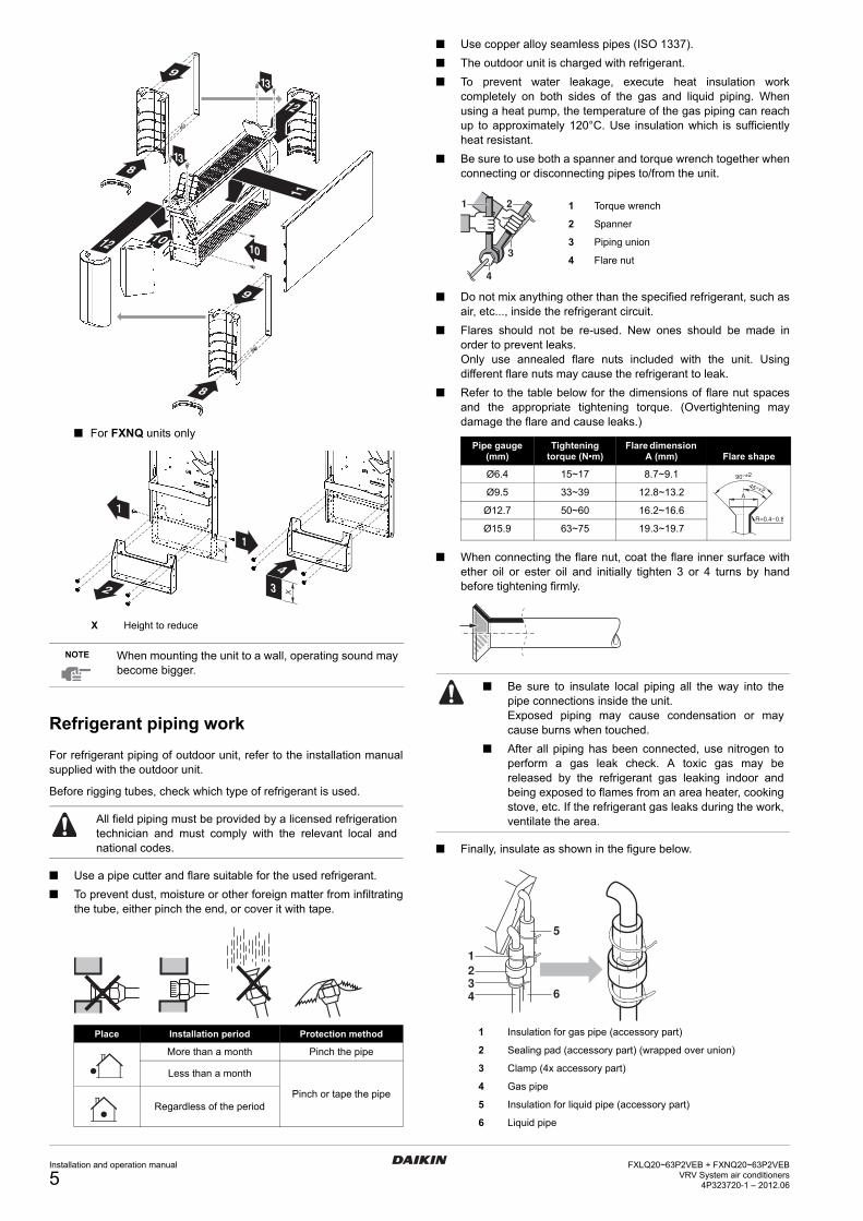
For FXLQ units only
note
(b)
For FXNQ units only
note
A Front side
B Air inlet direction
C Air outlet direction(a)
(a) The air outlet direction can be chosen by rotating the discharge grille.
NOTE Make sure no short circuit of air is caused whenplacing the unit directly under a windowsill.
≥100 ≥100
≥10
00
≤20
A
B
C
C
A
≥17
50
B
<17
50
C
B(b)
≤20 >20
C
A A
B
C
B
Model
20+25 32+40 50+63
A Width of air inlet 570 710 990
B Width of maintenance area 1030 1170 1450
C Air inlet direction
D Air outlet direction
NOTE Make sure no short circuit of air is caused whenplacing the unit directly under a windowsill.
≥100 ≥150
≥10
00
C
AB
625
D
D
≥17
50
C
<17
50DCD
C
DC
≤200 mm in case of wall mounting
100≤E≤200
EEE
100≤E≤200
Installation and operation manual
3FXLQ20~63P2VEB + FXNQ20~63P2VEB
VRV System air conditioners4P323720-1 – 2012.06

Indoor unit installation
As for the parts to be used for installation work, be sure to use theprovided accessories and specified parts designated by ourcompany.
Make sure wiring, piping and drain piping meets your customer'srequirements and must comply with local and national regulations.
How to open and close the front panel (for FXLQ units only)
To open the front panel, remove 4 screws from the corner pieces,unhook the corner pieces and remove the front panel as shown in thefigure below.
To close the front panel, use the opposite method.
Floorstanding installation
1 Level the indoor unit with theleveling screws (accessory part).If the floor is too uneven to levelthe unit, place the unit on a flatand level base.
2 If the unit is in danger of falling over, either fasten to the wallusing the holes provided, or fasten to the floor with a fieldsupplied floor fastener.
Wallmounted installation
1 Positioning of holes for fastening to the wall.Unit of measurement = mm.
2 The legs can be removed if the indoor unit is to be hung on awall. To do so, remove the legs and mount the 2 decorationstripsto the corner pieces as shown in the figures below.
For FXLQ units only
Ensure the unit is level when installed so that drainageflows smoothly. If inclined, water can leak.
Make sure that the floor is strong enough to bear the unitweight.
1
1
2
2
3
22
1 1
22
Check whether the wall is strong enough to bear theweight of the unit. If there is a risk, reinforce the wallbefore installing the unit.
Use the installation mount on the rear of the unit forinstallation.
The unit requires minimum 100 mmclearance on the bottomside for airintake and maximum 20 mmclearance from the wall by usingspacers (field supply).
Model A (mm)
20 + 25 590
32 + 40 730
50 + 63 1010
≤20
A205 205
192
232
1
1
5
6
7
3
5
2
6
5
2
5
44
A
100≤A≤200
FXLQ20~63P2VEB + FXNQ20~63P2VEBVRV System air conditioners4P323720-1 – 2012.06
Installation and operation manual
4
For FXNQ units only
Refrigerant piping work
For refrigerant piping of outdoor unit, refer to the installation manualsupplied with the outdoor unit.
Before rigging tubes, check which type of refrigerant is used.
Use a pipe cutter and flare suitable for the used refrigerant. To prevent dust, moisture or other foreign matter from infiltrating
the tube, either pinch the end, or cover it with tape.
Use copper alloy seamless pipes (ISO 1337). The outdoor unit is charged with refrigerant. To prevent water leakage, execute heat insulation work
completely on both sides of the gas and liquid piping. Whenusing a heat pump, the temperature of the gas piping can reachup to approximately 120°C. Use insulation which is sufficientlyheat resistant.
Be sure to use both a spanner and torque wrench together whenconnecting or disconnecting pipes to/from the unit.
Do not mix anything other than the specified refrigerant, such asair, etc..., inside the refrigerant circuit.
Flares should not be re-used. New ones should be made inorder to prevent leaks.Only use annealed flare nuts included with the unit. Usingdifferent flare nuts may cause the refrigerant to leak.
Refer to the table below for the dimensions of flare nut spacesand the appropriate tightening torque. (Overtightening maydamage the flare and cause leaks.)
When connecting the flare nut, coat the flare inner surface withether oil or ester oil and initially tighten 3 or 4 turns by handbefore tightening firmly.
Finally, insulate as shown in the figure below.
X Height to reduce
NOTE When mounting the unit to a wall, operating sound maybecome bigger.
All field piping must be provided by a licensed refrigerationtechnician and must comply with the relevant local andnational codes.
Place Installation period Protection method
More than a month Pinch the pipe
Less than a month
Pinch or tape the pipeRegardless of the period
13
9
10
8
9
8
10
13
12
12
11
1
1
2
4
3
X
X
Pipe gauge (mm)
Tightening torque (N•m)
Flare dimension A (mm) Flare shape
Ø6.4 15~17 8.7~9.1
Ø9.5 33~39 12.8~13.2
Ø12.7 50~60 16.2~16.6
Ø15.9 63~75 19.3~19.7
Be sure to insulate local piping all the way into thepipe connections inside the unit.Exposed piping may cause condensation or maycause burns when touched.
After all piping has been connected, use nitrogen toperform a gas leak check. A toxic gas may bereleased by the refrigerant gas leaking indoor andbeing exposed to flames from an area heater, cookingstove, etc. If the refrigerant gas leaks during the work,ventilate the area.
1 Insulation for gas pipe (accessory part)
2 Sealing pad (accessory part) (wrapped over union)
3 Clamp (4x accessory part)
4 Gas pipe
5 Insulation for liquid pipe (accessory part)
6 Liquid pipe
1 2
4
3
1 Torque wrench
2 Spanner
3 Piping union
4 Flare nut
R=0.4~0.8
45° ±2
90°±2
A
1234 6
5
Installation and operation manual
5FXLQ20~63P2VEB + FXNQ20~63P2VEB
VRV System air conditioners4P323720-1 – 2012.06
Cautions for brazing
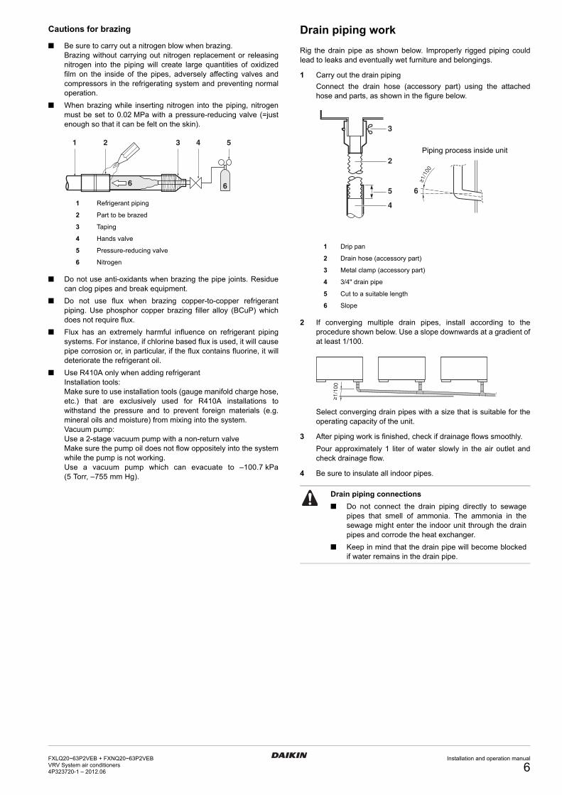
Be sure to carry out a nitrogen blow when brazing.Brazing without carrying out nitrogen replacement or releasingnitrogen into the piping will create large quantities of oxidizedfilm on the inside of the pipes, adversely affecting valves andcompressors in the refrigerating system and preventing normaloperation.
When brazing while inserting nitrogen into the piping, nitrogenmust be set to 0.02 MPa with a pressure-reducing valve (=justenough so that it can be felt on the skin).
Do not use anti-oxidants when brazing the pipe joints. Residuecan clog pipes and break equipment.
Do not use flux when brazing copper-to-copper refrigerantpiping. Use phosphor copper brazing filler alloy (BCuP) whichdoes not require flux.
Flux has an extremely harmful influence on refrigerant pipingsystems. For instance, if chlorine based flux is used, it will causepipe corrosion or, in particular, if the flux contains fluorine, it willdeteriorate the refrigerant oil.
Use R410A only when adding refrigerantInstallation tools:Make sure to use installation tools (gauge manifold charge hose,etc.) that are exclusively used for R410A installations towithstand the pressure and to prevent foreign materials (e.g.mineral oils and moisture) from mixing into the system.Vacuum pump:Use a 2-stage vacuum pump with a non-return valveMake sure the pump oil does not flow oppositely into the systemwhile the pump is not working.Use a vacuum pump which can evacuate to –100.7 kPa(5 Torr, –755 mm Hg).
Drain piping work
Rig the drain pipe as shown below. Improperly rigged piping couldlead to leaks and eventually wet furniture and belongings.
1 Carry out the drain pipingConnect the drain hose (accessory part) using the attachedhose and parts, as shown in the figure below.
2 If converging multiple drain pipes, install according to theprocedure shown below. Use a slope downwards at a gradient ofat least 1/100.
Select converging drain pipes with a size that is suitable for theoperating capacity of the unit.
3 After piping work is finished, check if drainage flows smoothly.Pour approximately 1 liter of water slowly in the air outlet andcheck drainage flow.
4 Be sure to insulate all indoor pipes.
1 Refrigerant piping
2 Part to be brazed
3 Taping
4 Hands valve
5 Pressure-reducing valve
6 Nitrogen
1 2 3 4 5
66
1 Drip pan
2 Drain hose (accessory part)
3 Metal clamp (accessory part)
4 3/4" drain pipe
5 Cut to a suitable length
6 Slope
Drain piping connections
Do not connect the drain piping directly to sewagepipes that smell of ammonia. The ammonia in thesewage might enter the indoor unit through the drainpipes and corrode the heat exchanger.
Keep in mind that the drain pipe will become blockedif water remains in the drain pipe.
2
3
5
4
6
≥1/
100
Piping process inside unit
≥1/
100
FXLQ20~63P2VEB + FXNQ20~63P2VEBVRV System air conditioners4P323720-1 – 2012.06
Installation and operation manual
6

Electric wiring work
General instructions
Be sure to use a dedicated power supply. Never use a powersupply shared by another appliance.
All field supplied parts and materials and electric works must beconform to local and national regulations.
All wiring must be performed by an authorized electrician. Use copper wire only. Follow the "Wiring diagram" attached to the unit to wire the
outdoor unit, indoor units and the remote controller. For detailshow to mount the remote controller, refer to the "Installationmanual of the remote controller".
Attach the earth leakage circuit breaker and fuse to the powersupply line.
A main switch or other means for disconnection, having acontact separation in all poles, must be incorporated in the fixedwiring in accordance with relevant local and national legislation.Note that the operation will restart automatically if the mainpower supply is turned off and then turned back on again.
This system consists of multiple indoor units. Mark each indoorunit as unit A, unit B..., and be sure the terminal block wiring tothe outdoor unit and BS unit are properly matched. If wiring andpiping between the outdoor unit and an indoor unit aremismatched, the system may cause a malfunction.
Be sure to ground the air conditioner. Do not connect the ground wire to:
- gas pipes: might cause explosions or fire if gas leaks.- telephone ground wires or lightning rods: might cause
abnormally high electric potential in the ground during lightning storms.
- plumbing pipes: no grounding effect if hard vinyl piping is used.
Make sure electrical wires are strippedequally.
Precautions
1 Observe the notes mentioned below when wiring to the powersupply terminal board.- Use a round crimp-style terminal for insulation sleeve for
connection to the terminal block for wiring the units. When none are available, follow the instructions below.
- Do not connect wires of different gauge to the same power supply terminal. (Looseness in the connection may cause overheating.)
- When connecting wires of the same dimension, connect them according to the figure.
Use the specified electric wire. Connect the wire securely to theterminal. Lock the wire down without applying excessive force tothe terminal. Use torques according to the table below.
- When attaching the control box lid, make sure not to pinch any wires and make sure that the wiring does not come in contact with the piping and sharp edges.
- After all wiring connections are done, fill in any gaps in the casing wiring holes with putty or insulation material (field supply) thus to prevent small animals or dirt from entering the unit from outside and causing short circuits in the control box.
2 Keep total current of crossover wiring between indoor units lessthan 12 A. Branch the line outside the terminal board of the unitin accordance with electrical equipment standards, when usingtwo power wiring greater than 2 mm2 (Ø1.6).The branch must be sheathed in order to provide an equal orgreater degree of insulation as power supply wiring itself.
3 Do not connect wires of different dimensions to the samegrounding terminal. Looseness in the connection maydeteriorate the protection.
4 Remote controller cords and wires connecting the units shouldbe located at least 50 mm away from power supply wiring. Notfollowing this guideline may result in malfunction due toelectrical noise.
5 For the remote controller wiring, refer to the "Installation manualof the remote controller" supplied with the remote controller.
6 Use only specified wires and tightly connect wires to theterminals. Be careful that wires do not place external stress onthe terminals. Keep wiring in neat order so that they do notobstruct other equipment such as popping open the control boxcover. Make sure the cover closes tight. Incomplete connectionscould result in overheating, and in the worse case, electric shockor fire.
7 Fasten wiring with clamps (accessory part).
DANGER: ELECTRICAL SHOCK
Switch off all power supply before removing the switch boxservice panel or before making any connections ortouching electrical parts.
To avoid electric shock, be sure to disconnect the powersupply 1 minute or more before servicing the electricalparts. Even after 1 minute, always measure the voltage atthe terminals of main circuit capacitors or electrical partsand, before touching, be sure that those voltages are50 V DC or less.
When service panels are removed, live parts can be easilytouched by accident.Never leave the unit unattended during installation orservicing when service panel is removed.
Terminal SizeTightening
torque (N•m)
Terminal block for remote controller M3.5 0.79~0.97
Power supply terminal block M4 1.18~1.44
Ground terminal M4 1.44~1.94
1 2 3
1 Round crimp-style terminal
2 Attach insulation sleeve
3 Wiring
Installation and operation manual
7FXLQ20~63P2VEB + FXNQ20~63P2VEB
VRV System air conditioners4P323720-1 – 2012.06

Electrical characteristics
Specifications for field supplied fuses and wire
Allowable length of transmission wiring between indoor and outdoor units,and between the indoor unit and the remote controller is as follows:1. Outdoor unit - indoor unit: maximum 1000 m
(total wiring length: 2000 m)2. Indoor unit - remote controller: maximum 500 m
How to install the remote controller and wiring inside the unit
Remote controller installation
For FXLQ units only
If mounting a remote controller on the unit, mount the remotecontroller (optional accessory) as shown in the figure.
Open the left side lid of the control panel and mount the lower case ofthe remote controller.
Wiring installation
Remove the control box cover and connect the wiring.
If wiring from the piping side, wire as shown in the figure below.
Model Hz VoltsVoltage range
Power supply Fan motor
MCA MFA kW FLA
20
50/60 220-240/220 ±10%
0.3 16 0.015 0.2
25 0.3 16 0.015 0.2
32 0.6 16 0.025 0.5
40 0.6 16 0.025 0.5
50 0.6 16 0.035 0.5
63 0.6 16 0.035 0.5
MCA: Minimum Circuit Amps (A)MFA: Maximum Fuse Amps (A)FLA: Full Load Amps (A)
NOTE For details, refer to "Electrical data" in the technicaldata book.
Power supply wiring
Model Field fuses Wire Size
20~63 16 A H05VV-U3G Local codes
Model Wire Size
20~63 Sheathed wire (2) 0.75-1.25 mm2
NOTE For details, refer to "Wiring examples" on page 9.
NOTE Refer to the installation manual of the remote controllerfor instructions on fastening and wiring work.
1 Installation screw (2x)
2 Lower case of remote controller
3 Lid of control panel
1
2
3
1 Control box
2 Power supply wiring (field supply)
3 Remote controller wiring (field supply)
4 Transmission wiring (field supply)
5 Clamp fastener
6 Clamp (accessory part)
7 Cut off excess after fastening
NOTE For control box wiring, also refer to the "Electric WiringDiagram" label on the control box cover.
1 Pass through hole of opposite frame panel in same manner
2 Remote controller wiring
3 Transmission wiring
4 Power supply wiring and ground wiring
5 Control box
6 Fasten with clamp (accessory part)
Do not switch the remote controller wiring, transmissionwiring and power supply wiring when connecting the wiresto the terminal blocks.
1
432
7 6 5
3x3x3x
423
432
66
6
1
5
FXLQ20~63P2VEB + FXNQ20~63P2VEBVRV System air conditioners4P323720-1 – 2012.06
Installation and operation manual
8

Wiring examples
Fit the power supply wiring of each unit with a switch and fuse asshown in figure 1.
Complete system example (3 systems)
When using 1 remote controller for 1 indoor unit. (Normal operation)(See figure 2)
For group control or use with 2 remote controllers (See figure 4)
When including BS unit (See figure 3)
PRECAUTIONS
A single switch can be used to supply power to units on thesame system. However, branch switches and branch circuitbreakers must be selected carefully.
For a group control remote controller, choose the remotecontroller that suits the indoor unit which has the most functions.
Do not ground the equipment on gas pipes, water pipes,lightning rods or crossground with telephones. Impropergrounding could result in electric shock.
Field setting
Field setting must be made on the remote controller in function of theinstallation condition. Setting can be made by changing the "Mode number", "First
code No." and "Second code No.". For setting and operation, refer to the "Field settings" in the
installation manual of the remote controller.
Control by 2 Remote Controllers (Controlling 1 indoor unit by 2 remote controllers)
When using 2 remote controllers, one must be set to "MAIN" and theother to "SUB". Refer to the installatoin manual of the remotecontroller.
Computerised control (forced off and on/off operation)
1 Wire specifications and how to perform wiring- Connect input from outside to terminals T1 and T2 of the
terminal board (remote controller to transmission wiring).
2 Actuation- The following table explains "forced off" and "on/off
operations" in response to input A.
3 How to select forced off and on/off operation- Turn the power on and then use the remote controller to
select operation.- Set the remote controller to the field set mode. For details,
refer to the chapter "How to set in the field", in the remote controller manual.
- When in the field set mode, select mode No. 12, then set the first code No. to "1". Then set second code (position) No. to "01" for forced off and to "02" for on/off operation. (forced off at factory set.)
Centralized control
For centralized control, it is necessary to designate the group No. Fordetails, refer to the manual of each optional controller for centralizedcontrol.
1 Power supply 6 BS unit (only for heat recovery system)
2 Main switch
3 Outdoor unit 7 Power supply wiring
4 Indoor unit 8 Transmission wiring
5 Remote controller 9 Switch
10 Fuse
1 Outdoor unit
2 Indoor unit
3 Remote controller (optional accessories)
4 Most downstream indoor unit
5 For use with 2 remote controllers
6 BS unit
Wire specification Sheathed vinyl cord or cable (2 wire)
Gauge 0.75-1.25 mm2
Length Maximum 100 m
External terminal Contact that can ensure the minimum applicable load of 15 V DC, 10 mA
Forced off on/off operation
Input "on" stops operation input off on: turns on the unit (impossible by remote controllers)
Input "off" enables control input on off: turns off the unit by remote controller
F2 T1 T2FORCEDOFF
Input A
Installation and operation manual
9FXLQ20~63P2VEB + FXNQ20~63P2VEB
VRV System air conditioners4P323720-1 – 2012.06
Test operation
Refer to the installation manual of the outdoor unit.
The operation lamp of the remote controller will flash when an erroroccurs. Check the error code on the liquid crystal display to identifythe trouble.
If any of the items in following table are displayed on the remotecontroller, there may be a problem with the wiring or power, so checkthe wiring again.
Maintenance
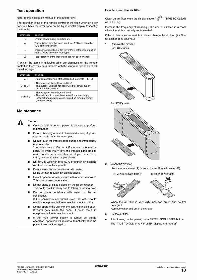
How to clean the air filter
Clean the air filter when the display shows " " (TIME TO CLEANAIR FILTER).
Increase the frequency of cleaning if the unit is installed in a roomwhere the air is extremely contaminated.
If the dirt becomes impossible to clean, change the air filter. (Air filterfor exchange is optional.)
1 Remove the air filter.For FXLQ units
For FXNQ units
2 Clean the air filter.Use vacuum cleaner (A) or wash the air filter with water (B).
When the air filter is very dirty, use soft brush and neutraldetergent.Remove water and dry in the shade.
3 Fix the air filter.
4 After turning on the power, press FILTER SIGN RESET button.The "TIME TO CLEAN AIR FILTER" display is turned off.
Error code Meaning
A8 Error in power supply to indoor unit
C1 Transmission error between fan driver PCB and controller PCB of the indoor unit
C6 Improper combination of fan driver PCB of the indoor unit or setting failure in control PCB type
U3 Test operation of the indoor unit has not been finished
Error code Meaning
There is a short circuit at the forced off terminals (T1, T2)
U4 or UH- The power on the outdoor unit is off- The outdoor unit has not been wired for power supply- Incorrect transmission
no display
- The power on the indoor unit is off- The indoor unit has not been wired for power supply- Incorrect transmission wiring, forced off wiring or remote
controller wiring
Caution
Only a qualified service person is allowed to performmaintenance.
Before obtaining access to terminal devices, all powersupply circuits must be interrupted.
Do not touch the internal parts during and immediatelyafter operation.Your hands may suffer burns if you touch the internalparts. To avoid injury, give the internal parts time toreturn to normal temperature or, if you must touchthem, be sure to wear proper gloves.
Do not use water or air of 50°C or higher for cleaningair filters and outside panels.
Do not wash the air conditioner with water.Doing so may result in an electric shock.
Do not operate for many hours with opened windows.This may cause condensation.
Do not stand or place objects on the air conditioner.This could result in injury due to falling or turning over.
Do not place containers with water on the airconditioner.If the containers are turned over, the water couldresult in equipment failure or electric shock and fire.
Do not operate the unit with the control panel lid open.If water gets inside the panel, it could result inequipment failure or electric shock.
If the main power supply is turned off duringoperation, operation will restart automatically after thepower turns back on again.
(A) Using a vacuum cleaner (B) Washing with water
FXLQ20~63P2VEB + FXNQ20~63P2VEBVRV System air conditioners4P323720-1 – 2012.06
Installation and operation manual
10

How to clean air outlet and outside panels
Clean with soft cloth. When it is difficult to remove stains, use water or neutral
detergent. Clean the air inlet grille when it is shut.
Removal and installation of discharge grille(for FXLQ units only)
Lift the rear using the front as a leverage. To install use the oppositemethod.
How to clean the drain strainer
The drain strainer clears dirt out of the drain water and prevents thepiping from clogging. However, if the strainer mesh gets clogged,water may overflow. Remove and wash the mesh with water beforeand after seasons when the unit is in use and once during thoseseasons.
1 Remove the drain strainer in the drip pan under the drain panand wash off any dirt that may have accumulated.
2 Return the drain strainer to its previous position so that thestrainer does not leak.
Start up after a long stop
Confirm the following: Check that the air inlet and outlet are not blocked. Remove any
obstacle. Check if the earth is connected.
Clean the air filter and outside panels. After cleaning the air filter, make sure to attach it.
Turn on the main power supply switch. The control panel display lights up when the power is turned on. To protect the unit, turn on the main power switch at least
6 hours before operation.
What to do when stopping the system for a long period
Turn on FAN OPERATION for half a day and dry the unit. Refer to the operation manual of the outdoor unit.
Cut off the power supply. When the main power switch is turned on, there is some power
consumption even if the system is not operating. The remote controller display is turned off when the main power
switch is turned off.
Disposal requirements
Dismantling of the unit, treatment of the refrigerant, of oil and of otherparts must be done in accordance with relevant local and nationallegislation.
NOTE Do not use gasoline, benzene, thinner, polishingpowder, liquid insecticide. It may cause discolouring orwarping.
Do not let the indoor unit get wet. It may cause anelectric shock or a fire.
NOTE Be sure to install the discharge grille in the same wayas before removal. Otherwise the air flow direction willbe avers with a short circuit of air or a wrong spreadingof air as possible result. Refer to the figures mentionedin the note on page 3.
1 Drip pan
2 Drain strainer (take out)
NOTE Because cleaning requires removing the front panel,contact your local dealer.
2
1
1 2
Installation and operation manual
11FXLQ20~63P2VEB + FXNQ20~63P2VEB
VRV System air conditioners4P323720-1 – 2012.06

Wiring diagram
A1P..................PRINTED CIRCUIT BOARD
C1....................CAPACITOR (M1F)
F1U..................FUSE (B, 5 A, 250 V)
F2U..................FIELD FUSE
HAP ................. LIGHT EMITTING DIODE (SERVICE MONITOR - GREEN)
K1R~K3R ........MAGNETIC RELAY (M1F)
M1F .................MOTOR (INDOOR FAN)
Q1M.................THERMO SWITCH (M1F EMBEDDED)
Q1DI ................EARTH LEAK DETECTOR
R1T..................THERMISTOR (AIR)
R2T,R3T .......... THERMISTOR (COIL)
T1R..................TRANSFORMER (220-240 V/22 V)
X1M .................TERMINAL BLOCK (POWER SUPPLY)
X2M .................TERMINAL BLOCK (CONTROL)
Y1E..................ELECTRONIC EXPANSION VALVE
CONNECTOR OPTIONAL ACCESSORY
X18A................CONNECTOR (WIRING ADAPTOR FORELECTRICAL APPENDICES)
WIRED REMOTE CONTROLLER
R1T..................THERMISTOR (AIR)
SS1..................SELECTOR SWITCH (MAIN/SUB)
: TERMINAL BLOCK BLK : BLACK PNK : PINK: CONNECTOR BLU : BLUE RED : RED: TERMINAL BRN : BROWN WHT : WHITE: FIELD WIRING ORG : ORANGE YLW : YELLOW: PROTECTIVE EARTH (SCREW)
L : LIVEN : NEUTRAL
WIRED REMOTE CONTROLLER (OPTIONAL ACCESSORY) :
CONTROL BOX :
TRANSMISSION WIRING CENTRAL REMOTE CONTROLLER (SEE NOTE 1)
:
INPUT FROM OUTSIDE (SEE NOTE 2) :
NOTE 1. WHEN USING THE CENTRAL REMOTE CONTROLLER, SEE MANUAL FOR CONNECTION TO THE UNIT.2. WHEN CONNECTING THE INPUT WIRES FROM OUTSIDE, FORCED "OFF" OR "ON/OFF" CONTROL OPERATION CAN
BE SELECTED BY THE REMOTE CONTROLLER. SEE INSTALLATION MANUAL FOR MORE DETAILS.3. USE COPPER CONDUCTORS ONLY.
FXLQ20~63P2VEB + FXNQ20~63P2VEBVRV System air conditioners4P323720-1 – 2012.06
Installation and operation manual
12

Cop
yrig
ht 2
012
Dai
kin
4P323720-1 2012.06