Installation and Operation Manual - Bazell
27
Page 1 2010-15 Bazell Technologies Corporation. All rights reserved. May not be reproduced in whole or in part without the express written consent of Bazell Technologies. Installation and Operation Manual Microseparator™ System For ES4 Edgers Distributed Exclusively by: Satisloh North America N 116 , W 18111 Morse Drive Germantown, WI. 53022 Tel: (262) 255-6001 Fax: (262) 255-6002 Manufactured for Satisloh by: Bazell Technologies Corporation 5066 Commercial Circle Concord, CA. 94520 Tel: (925) 603-0900 Fax (925) 603-0901 Email: [email protected] Web: www.bazell.com Bazell Technologies Corporation is a Satisloh Technology Partner M000021_D June 2015
Transcript of Installation and Operation Manual - Bazell
Page 1
2010-15 Bazell Technologies Corporation. All rights reserved. May not be reproduced in whole or in part without
the express written consent of Bazell Technologies.
Installation and Operation Manual
Microseparator™ System For ES4 Edgers Distributed Exclusively by: Satisloh North America N 116 , W 18111 Morse Drive Germantown, WI. 53022 Tel: (262) 255-6001 Fax: (262) 255-6002 Manufactured for Satisloh by: Bazell Technologies Corporation 5066 Commercial Circle Concord, CA. 94520 Tel: (925) 603-0900 Fax (925) 603-0901 Email: [email protected] Web: www.bazell.com Bazell Technologies Corporation is a Satisloh Technology Partner M000021_D June 2015

Page 2
2010-15 Bazell Technologies Corporation. All rights reserved. May not be reproduced in whole or in part without
the express written consent of Bazell Technologies.
TABLE OF CONTENTS TABLE OF CONTENTS ....................................................................... 2
PRODUCT DEFINITION ................................................................... 4
OPERATOR SAFETY .......................................................................... 4
INSTALLATION LIMITATIONS ..................................................... 5
SPECIFICATIONS .............................................................................. 5
RECEIVING AND INSPECTION ..................................................... 5
LIFTING ................................................................................................ 5
INSTALLATION – ELECTRICAL ..................................................... 6
INSTALLATION – PIPING .............................................................. 6
INLET .................................................................................................... 6 OUTLET ................................................................................................. 7 WATER MAKE-UP ................................................................................... 7 AIR SUPPLY ........................................................................................... 8 CHILLER SUPPLY (TEMPERATURE CONTROL OPTIONAL) ........................... 8 DUPLEX FILTERS .................................................................................... 9
START-UP .......................................................................................... 10
FILL TANK ........................................................................................... 10
CONTROL PANEL FUNCTIONS .................................................... 10
STARTING AND STOPPING .................................................................... 10
ALARMS .............................................................................................. 11
LOW LEVEL TANK ALARM ..................................................................... 11 HIGH LEVEL TANK ALARM .................................................................... 11 LOW TEMPERATURE ALARM .................................................................. 11 HIGH TEMPERATURE ALARM ................................................................. 11 LOW AIR PRESSURE ALARM.................................................................. 11 NO WORK ........................................................................................... 11 AUTO FILL MODE ................................................................................ 11 LEVEL SWITCH ERROR ......................................................................... 11 MOTOR OVERLOAD .............................................................................. 11 OVERLOAD .......................................................................................... 12 EMERGENCY STOP ............................................................................... 12
DAILY PRODUCT STARTUP .......................................................... 12
TANK CLEANING ............................................................................. 12
CONTROL SUMMARY ..................................................................... 13
FUNCTION ........................................................................................... 13 SETUP ................................................................................................. 13 CALIBRATION ...................................................................................... 14 WARNINGS, ALERTS AND FAULTS ......................................................... 14
SCREEN CLEANING ........................................................................ 16
SYSTEM DIMENSIONS AND UTILITIES .................................. 18

Page 3
2010-15 Bazell Technologies Corporation. All rights reserved. May not be reproduced in whole or in part without
the express written consent of Bazell Technologies.
DRAWING 6SBTB001 ......................................................................... 18
EDGER SYSTEM PROCESS FLOW ............................................... 19
DRAWING # 6SBTE200 ..................................................................... 19
DRAWING # 6SBTE205 ................................................................ 20
SYSTEM PARTS LIST ...................................................................... 21
DRAWING # 6SBTE150 ................................................................ 22
LIMITATIONS OF WARRANTY .................................................... 27
DOCUMENT REPRESENTATION .............................................................. 27 CONTACTING BAZELL TECHNOLOGIES ................................................... 27
Page 4
2010-15 Bazell Technologies Corporation. All rights reserved. May not be reproduced in whole or in part without
the express written consent of Bazell Technologies.
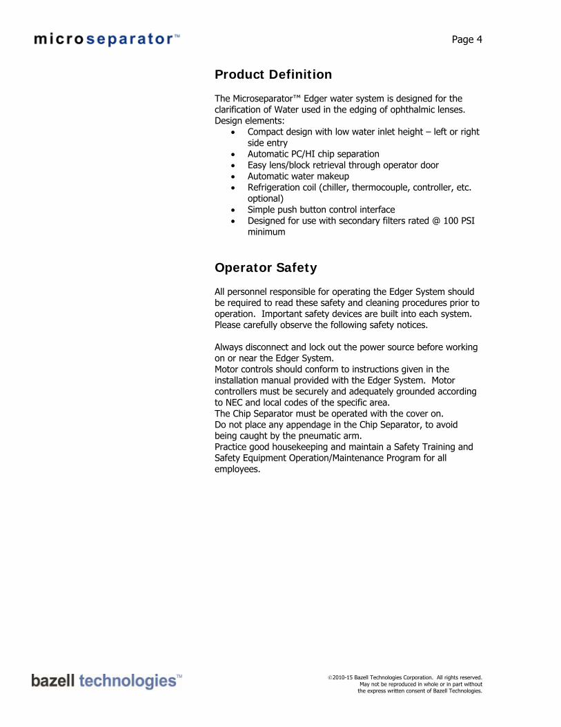
Product Definition The Microseparator™ Edger water system is designed for the clarification of Water used in the edging of ophthalmic lenses. Design elements:
Compact design with low water inlet height – left or right side entry
Automatic PC/HI chip separation Easy lens/block retrieval through operator door Automatic water makeup Refrigeration coil (chiller, thermocouple, controller, etc.
optional) Simple push button control interface Designed for use with secondary filters rated @ 100 PSI
minimum
Operator Safety All personnel responsible for operating the Edger System should be required to read these safety and cleaning procedures prior to operation. Important safety devices are built into each system. Please carefully observe the following safety notices. Always disconnect and lock out the power source before working on or near the Edger System. Motor controls should conform to instructions given in the installation manual provided with the Edger System. Motor controllers must be securely and adequately grounded according to NEC and local codes of the specific area. The Chip Separator must be operated with the cover on. Do not place any appendage in the Chip Separator, to avoid being caught by the pneumatic arm. Practice good housekeeping and maintain a Safety Training and Safety Equipment Operation/Maintenance Program for all employees.

Page 5
2010-15 Bazell Technologies Corporation. All rights reserved. May not be reproduced in whole or in part without
the express written consent of Bazell Technologies.
Installation Limitations
Specifications Model Name ES4 Edger System
Polycarbonate Removal Self-cleaning Chip Separator
Maximum Flow Rate 76 l/min (20 GPM)
Water Tank 304 SS, capacity 80 L (21 gals)
Water Pump Brinkmann Plastic body
Cooling Coil Copper
Control Panel Per the drawings attached Note: The Microseparator™ ES4 Edger System is designed to support the recirculating water requirements of (2) edgers only. Any attempt by the owner to utilize the equipment for other than the intended purpose is at his or her own risk.
Receiving and Inspection As soon as possible upon receipt of shipment, machine should be uncrated and packing list checked. Any shortages should be reported to Bazell Technologies Corporation immediately. If damage has occurred during transit, file a claim with the carrier and notify Bazell Technologies of such action.
Lifting Lift tank from the bottom only using fork lift. Do not lift or strap to the upper half of machine. Machine is top heavy – be sure to stabilize load during transport.

Page 6
2010-15 Bazell Technologies Corporation. All rights reserved. May not be reproduced in whole or in part without
the express written consent of Bazell Technologies.
Installation – Electrical Refer to: 6SBTE150 Electrical Prints
Before proceeding further with the installation, make sure that electrical power is:
Domestic: 208 VAC, 10A, 60 Hz, 3ⱷ International: 400 VDC, 6A, 50 Hz, 3ⱷ
Open the control panel: shown with optional international voltage.
Visually check for shipping damage Pull test the wiring by gently tugging on
all wiring at their connections
Installation – Piping
Inlet Position the system to allow gravity drain from the generator to the Edger System. Maintain full pipe size with minimal bends. Maintain a minimum slope of ¼” per linear foot (2 cm/m) of pipe for good drainage. Do not use flexible hose for drain line. There are two inlets, one on each side of the tank.
Water Inlet
Page 7
2010-15 Bazell Technologies Corporation. All rights reserved. May not be reproduced in whole or in part without
the express written consent of Bazell Technologies.
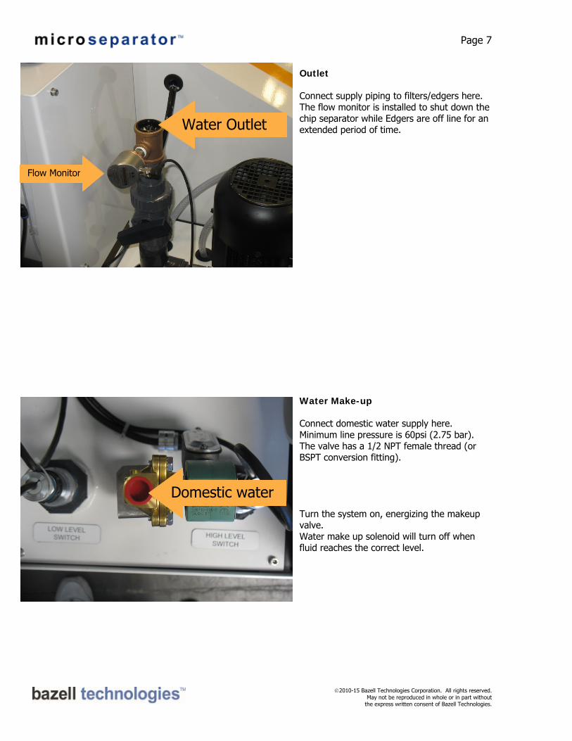
Outlet Connect supply piping to filters/edgers here. The flow monitor is installed to shut down the chip separator while Edgers are off line for an extended period of time.
Water Make-up Connect domestic water supply here. Minimum line pressure is 60psi (2.75 bar). The valve has a 1/2 NPT female thread (or BSPT conversion fitting). Turn the system on, energizing the makeup valve. Water make up solenoid will turn off when fluid reaches the correct level.
Domestic water
Flow Monitor
Water Outlet

Page 8
2010-15 Bazell Technologies Corporation. All rights reserved. May not be reproduced in whole or in part without
the express written consent of Bazell Technologies.
Air supply Connect 70 psi clean dry air.
Chiller Supply (Temperature control optional)
Shown with optional temperature control valve. Connect chilled water supply to coil here using hoses provided.
Air

Page 9
2010-15 Bazell Technologies Corporation. All rights reserved. May not be reproduced in whole or in part without
the express written consent of Bazell Technologies.
Duplex filters
Assemble inlet and outlet piping as shown. Final assembly must have clearance for 3 way valves to turn 90 degrees from position shown. For an overall diagram of the system, please see page 18. Also assemble drain piping as shown on left.
OUTLET
OUTLET
INLET

Page 10
2010-15 Bazell Technologies Corporation. All rights reserved. May not be reproduced in whole or in part without
the express written consent of Bazell Technologies.
Start-up Fill Tank Fill the tank with water. Total system volume approximately 80 liters (21 gal). Verify 70psi air to Filter/Regulator. Verify incoming voltage matches voltage rating on panel legend. Verify supply line to filters/edgers are secure. Verify fluid lines to chiller are secure. Turn on main breaker.
Control Panel Functions Starting and Stopping Press the START button to place the system into operation. To normally stop the Edger, press the STOP button. Do not use the EMERGENCY STOP button for normal stopping. Starting the system will start the Water Supply Pump, and Chip Separator.

Page 11
2010-15 Bazell Technologies Corporation. All rights reserved. May not be reproduced in whole or in part without
the express written consent of Bazell Technologies.
Alarms When the alarm beacon is blinking, one of the following has occurred: Low Level Tank Alarm Tank level is below minimum height for extended amount of time. Check Water is not held up in the Chip Separator, press Start to initiate water makeup. Verify Water Make up is on and Water Make up Valve is operational. High Level Tank Alarm Tank level is above Maximum Height. Check Chip Separator and Edger Tank Screen for Held up water, clear if required. Lower water level in Tank. Clear High Level Alarm. Press green “START” button to Start Edger Tank Low Temperature Alarm Indicates Low Water Temperature. Check Chiller supply for correct temperature and flow to Edger, verify Chiller valve is operational. High Temperature Alarm Indicates High Water Temperature. Check Chiller supply for correct temperature and flow to Edger, verify Chiller valve is operational. Low Air Pressure Alarm Check supply of service air to machine. Ensure supply valve is open. Check pressure indication on air regulator. No Work Indicates No Water Flow to process supply; Chip Separator will go to standby mode. Chip Separator will automatically restart once Water Flow is resumed. Auto Fill Mode Start System in Auto mode; Press Green Start button to start Auto Fill Mode. Press Green Start button again to Fill Tank. Level Switch Error Check High and Low level switches are able to move freely in tank unobstructed. Motor Overload Indicates the motor overload relay has tripped. A qualified electrician should investigate. Consult electrical diagram or Bazell Technologies directly for more information.

Page 12
2010-15 Bazell Technologies Corporation. All rights reserved. May not be reproduced in whole or in part without
the express written consent of Bazell Technologies.
Overload Indicates a circuit breaker within the electrical panel has tripped. A qualified electrician should investigate. Consult electrical diagram or Bazell Technologies directly for more information. Emergency Stop Indicates red Emergency Stop button set; Reminds operator to reset button. Pull out Emergency Stop button to reset.
Daily Product Startup Check air pressure gauge – set to 70 psi Check chip separator bin – empty if necessary Turn on Main Breaker and depress START
Tank Cleaning Frequency of manual tank cleaning is determined by the volume of production - especially non-chip debris of plastics. Because the edgers use straight water without water additives there is the possibility of fungus or bacteria growing within the system. Any additive used must be compatible with the machine tool.
Page 13
2010-15 Bazell Technologies Corporation. All rights reserved. May not be reproduced in whole or in part without
the express written consent of Bazell Technologies.
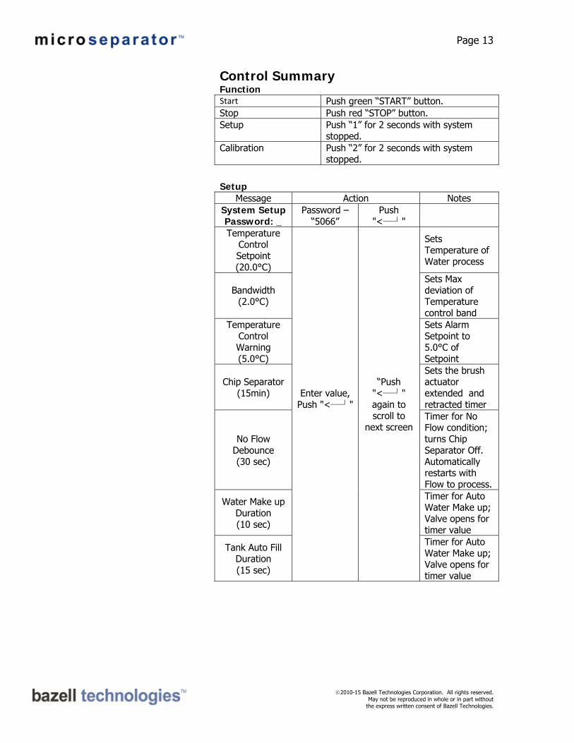
Control Summary Function Start Push green “START” button. Stop Push red “STOP” button. Setup Push “1” for 2 seconds with system
stopped. Calibration Push “2” for 2 seconds with system
stopped.
Setup
Message Action Notes System Setup Password: _
Password – “5066”
Push "˂─┘"
Temperature Control Setpoint (20.0°C)
Enter value, Push "˂─┘"
“Push "˂─┘" again to scroll to
next screen
Sets Temperature of Water process
Bandwidth (2.0°C)
Sets Max deviation of Temperature control band
Temperature Control Warning (5.0°C)
Sets Alarm Setpoint to 5.0°C of Setpoint
Chip Separator (15min)
Sets the brush actuator extended and retracted timer
No Flow Debounce (30 sec)
Timer for No Flow condition; turns Chip Separator Off. Automatically restarts with Flow to process.
Water Make up Duration (10 sec)
Timer for Auto Water Make up; Valve opens for timer value
Tank Auto Fill Duration (15 sec)
Timer for Auto Water Make up; Valve opens for timer value

Page 14
2010-15 Bazell Technologies Corporation. All rights reserved. May not be reproduced in whole or in part without
the express written consent of Bazell Technologies.
Calibration System Setup Password: _
Password – “5066”
Push "˂─┘"
Minimum 4mA Milliamp (4mA)
Enter value, Push "˂─┘"
“Push "˂─┘" again to scroll to
next screen
Sets Minimum mA scaling
Minimum Temperature
(0.0°C)
Sets Minimum Temperature
Maximum 20mA Milliamp (20mA)
Sets Maximum mA scaling
Maximum Temperature
(100.0°C)
Sets Maximum Temperature
Warnings, Alerts and Faults
Edger Tank Low Level
Tank water level is below minimum height for extended amount of time. Check Chip Separator or Edger Tank Screen for Held up water, clear if required. Press Start to initiate water makeup. Verify Water Make up is on and Water Make up Valve is operational.
Edger Tank High Level
Tank water level is above Maximum Height. Check Chip Separator or Edger Tank Screen for Held up water, clear if required. Lower water level in Tank. Clear High Level Alarm. Press green “START” button to Start Edger Tank
Edger Tank Emergency Stop
Indicates red Emergency Stop button set; Reminds operator to reset button. Pull out Emergency Stop button to reset.
Edger Tank Air Pressure Low
Indicates inadequate utility air supply; Protects operating without Chip Separator motive air. Check air pressure at regulator; Gauge on regulator should read 75PSI; Check building air supply valve open.
Auto Fill Mode
Start System in Auto mode; Press Green Start button to start Auto Fill Mode. Press Green Start button again to Fill Tank.
Level Switch Error
Check High and Low level switches are able to move freely in tank unobstructed.
Electrical Overload
Indicates circuit breaker or motor overload tripped; Protects panel against valve solenoid or motor winding overcurrent condition. Refer to qualified electrical service personal; Disconnect power and inspect electrical panel; repair or replace offending load.
No Work Indicates no Water Flow to process supply;

Page 15
2010-15 Bazell Technologies Corporation. All rights reserved. May not be reproduced in whole or in part without
the express written consent of Bazell Technologies.
Chip Separator will go to standby mode. Chip Separator will automatically restart once Water Flow is resumed.
Low Temperature Alarm
Indicates Low Water Temperature. Check Chiller supply for correct temperature and flow to Edger, verify Chiller valve is operational.
High Temperature Alarm
Indicates High Water Temperature. Check Chiller supply for correct temperature and flow to Edger, verify Chiller valve is operational.

Page 16
2010-15 Bazell Technologies Corporation. All rights reserved. May not be reproduced in whole or in part without
the express written consent of Bazell Technologies.
Screen Cleaning
Tilt screen to remove/replace. Flush screen thoroughly from the back side with water. If necessary brush the fine mesh (top side) of the screen with soft nylon bristle brush. Do not use a wire brush.
Press cleaned screen firmly into place.

Page 17
2010-15 Bazell Technologies Corporation. All rights reserved. May not be reproduced in whole or in part without
the express written consent of Bazell Technologies.
Be sure the screen is firmly pressed against bottom stop.
Be sure the screen is pressed firmly against the chip separator base.
Page 18
2010-15 Bazell Technologies Corporation. All rights reserved. May not be reproduced in whole or in part without
the express written consent of Bazell Technologies.
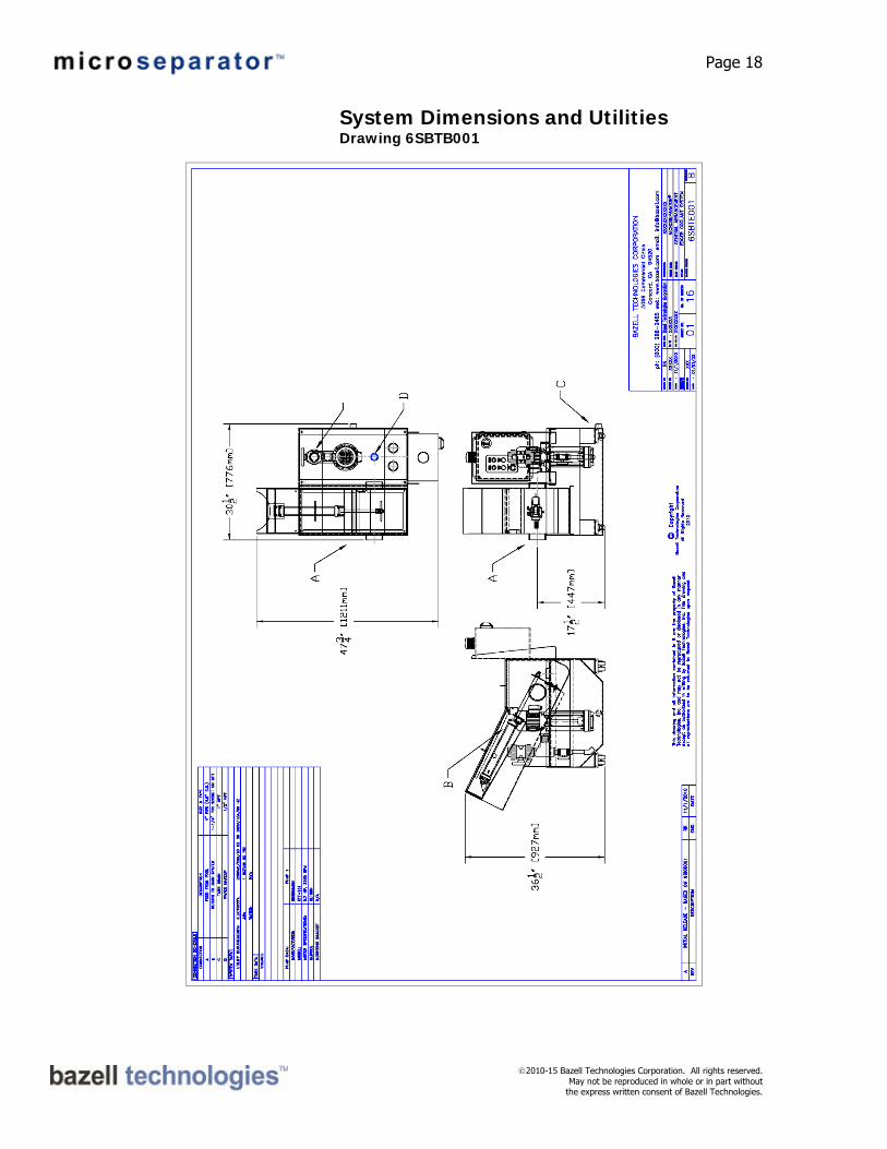
System Dimensions and Utilities Drawing 6SBTB001

Page 19
2010-15 Bazell Technologies Corporation. All rights reserved. May not be reproduced in whole or in part without
the express written consent of Bazell Technologies.
EDGER SYSTEM PROCESS FLOW Drawing # 6SBTE200

Page 20
2010-15 Bazell Technologies Corporation. All rights reserved. May not be reproduced in whole or in part without
the express written consent of Bazell Technologies.
Drawing # 6SBTE205

Page 21
2010-15 Bazell Technologies Corporation. All rights reserved. May not be reproduced in whole or in part without
the express written consent of Bazell Technologies.
System Parts List Refer to drawing 6SBTE205
ITEM QTY PART NO. DESCRIPTION MATERIAL/SPEC 1 1 5090001-24VDC SOLENOID VALVE SMC 24VDC 2 1 520-6BAZN110 CONTROL PANEL RELAY LOGIC 3 1 6200013 FILTER/REG/PRESSURE SWITCH SMC AR20 4 1 6200009 AIR LIMIT VALVE SMC 5 1 6150350N-X AIR CYLINDER 50 X 350 6 1 CON-6SATE001 POLYJECTOR CABINET 304SS 7 2 521-AS2OY2000 FLOAT SWITCH N/O 8 1 P-KTF151/290 PUMP, BRINKMANN 3/4HP 190/380V 9 1 CON-6SBTE057A BRUSH ASSEMBLY INCLUDES 9A,B & C 9A 1 CON-6SBTE057 BRUSH BRACKET 304SS 9B 1 CON-6SATD027 BRUSH NYLON 9C 2 CON-6SATE022 GASKET BUNA 10 1 521-AS2OY1200 FLOAT SWITCH N/O 11 4 T-CAST-4W779 CASTERS STEEL 1 5090011-24VDC SOLENOID, WATER MAKEUP ASCO ½” 24VDC 1 521-SI5000 FLOW MONITOR IFM 24VDC 1 T-6SBTE030 SCREEN ASSEMBLY 304SS/NYLON MESH 1 T-170M76X76 SCREEN MESH NYLON 175MICRON 1 T-6SATW040 COOLING COIL COPPER ½”
Page 22
2010-15 Bazell Technologies Corporation. All rights reserved. May not be reproduced in whole or in part without
the express written consent of Bazell Technologies.
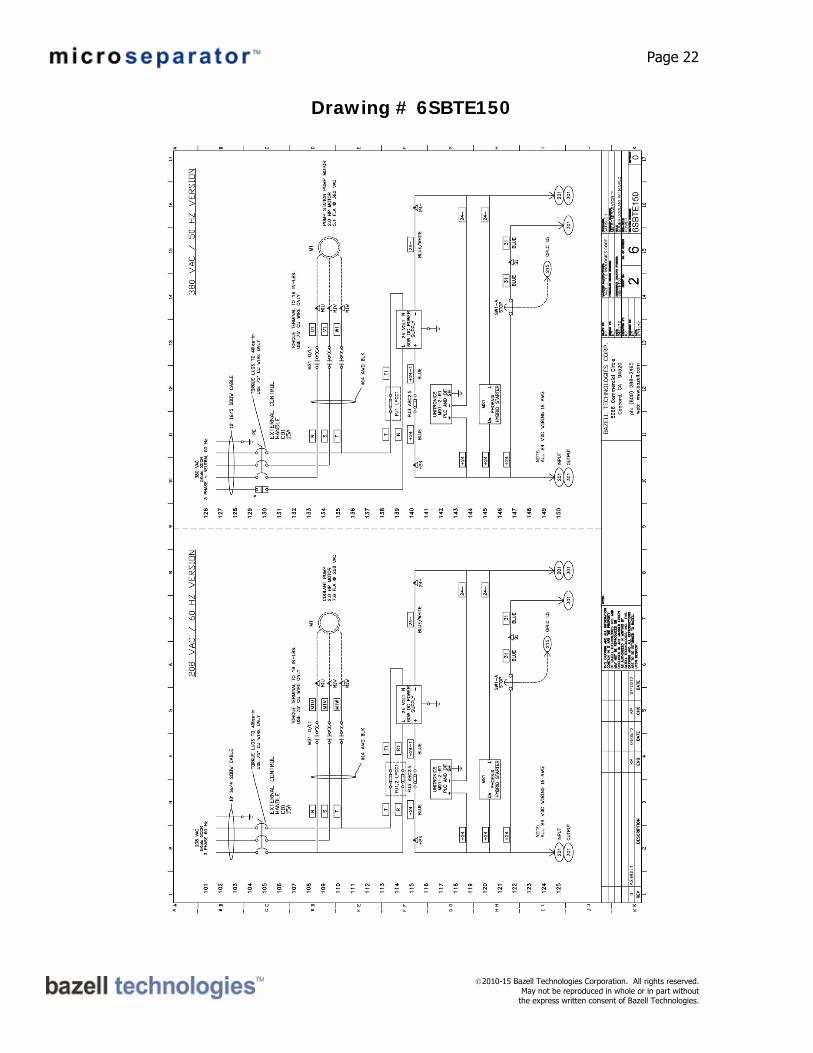
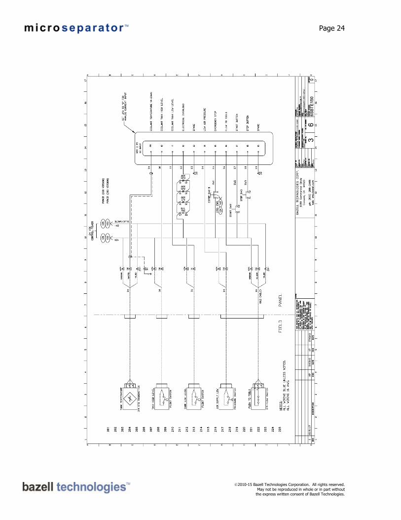
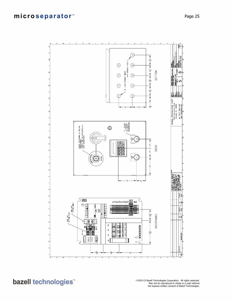
Drawing # 6SBTE150

Page 23
2010-15 Bazell Technologies Corporation. All rights reserved. May not be reproduced in whole or in part without
the express written consent of Bazell Technologies.
Page 24
2010-15 Bazell Technologies Corporation. All rights reserved. May not be reproduced in whole or in part without
the express written consent of Bazell Technologies.
Page 25
2010-15 Bazell Technologies Corporation. All rights reserved. May not be reproduced in whole or in part without
the express written consent of Bazell Technologies.

Page 26
2010-15 Bazell Technologies Corporation. All rights reserved. May not be reproduced in whole or in part without
the express written consent of Bazell Technologies.

Page 27
2010-15 Bazell Technologies Corporation. All rights reserved. May not be reproduced in whole or in part without
the express written consent of Bazell Technologies.
Limitations of Warranty Bazell Technologies Corporation shall not be liable, to any extent whatsoever, for any damages resulting from or arising out of the use or performance of this product and related documentation or the procedures specified in this manual, regardless of foreseeability or the form of action, whether in contract, tort (including negligence), breach of warranty, strict liability or otherwise, and including but not limited to damages resulting from loss of data, loss of anticipated profits, or any special, indirect, incidental or consequential damages. In no even shall Bazell Technologies Corporation liability to the user exceed the amount paid by the user to Bazell Technologies Corporation hereunder. The user assumes full responsibility for the results obtained from the use of this product and related documentation and for application of such results. Document Representation This documentation is provided in good faith but without warranty as to correctness, accuracy, reliability, omissions, or otherwise except as provided in writing by an officer of Bazell Technologies Corporation. Contacting Bazell Technologies Bazell Technologies Corporation 5066 Commercial Circle Concord, CA. 94520 Tel: (925) 603-0900 Fax: (925) 603-0901 Email: [email protected] web: www.bazell.com