INSTALLATION AND OPERATION MANUAL AND …images.cooksdirect.com/Owners_Manuals/Market-Forge… ·...
47
1 INSTALLATION AND OPERATION MANUAL AND PARTS LIST GAS FIRED STEAMER MODELS ETP-5G ETP-10G ___________________________________________________________________________ S-6501 35 Garvey Street, Everett, MA 02149-4403 Rev. B 06/08 Tel: (617) 387-4100, (866) 698-3188 Fax: (617) 387-4456, (800) 227-2659 [email protected], www.mfii.com
Transcript of INSTALLATION AND OPERATION MANUAL AND …images.cooksdirect.com/Owners_Manuals/Market-Forge… ·...

INSTALLATION AND OPERATION MANUAL AND PARTS LIST GAS FIRED STEAMER
MODELS ETP-5G
ETP-10G
__________________ S-6501 Rev. B 06/08
1
_________________________________________________________
35 Garvey Street, Everett, MA 02149-4403 Tel: (617) 387-4100, (866) 698-3188
Fax: (617) 387-4456, (800) 227-2659 [email protected], www.mfii.com

2
IMPORTANT NOTES FOR INSTALLATION AND OPERATION Retain this manual for future reference.
This is the safety alert symbol. It is used to alert you to potential personal injury hazards. Obey all safety messages that follow this symbol to avoid possible injury or death.
WARNING: Improper installation, adjustment, alteration, service or maintenance can cause property damage, injury or death. Read the installation, operating and maintenance instructions thoroughly before installing, servicing or operating this equipment.
FOR YOUR SAFETY: Do not store or use gasoline or other flammable vapors and liquids in the vicinity of this or any other appliance.
PURCHASER: Instructions to be followed in the event that the operator of this appliance smells gas must be posted in a prominent location. This information shall be obtained by consulting the local gas supplier.
IMPORTANT Do not attempt to operate this unit in the event of power failure. Adequate clearances must be maintained for safe and proper operation. The appliance area must be kept free and clear of combustibles. Do not obstruct the flow of combustion and ventilation air. Contact the factory, the factory representative or a local service company to perform maintenance and repairs should the appliance malfunction. Refer to warranty terms.
Intended for commercial use only. Not for household use.

3
TABLE OF CONTENTS
DESCRIPTION PAGE 1.0 SERVICE CONNECTIONS..................................................................................................4 2.0 INTRODUCTION..................................................................................................................6 3.0 INSTALLATION....................................................................................................................7 4.0 PERFORMANCE CHECK..................................................................................................14 5.0 OPERATION INSTRUCTIONS ..........................................................................................15 6.0 PREVENTIVE MAINTENANCE..........................................................................................24 7.0 GENERAL TROUBLESHOOTING GUIDE .........................................................................34 8.0 MAINTENANCE ...............................................................................................................35 9.0 PARTS...............................................................................................................................37

1.0 SERVICE CONNECTIONS
4

1.0 SERVICE CONNECTIONS
5

6
2.0 INTRODUCTION DESCRIPTION The ETP-5G and ETP-10G are gas fired pressureless steam cookers. The cooking compartments are equipped with a three-piece door with inner gasket plate isolated from the exterior surface. Door latch operates by slam action for positive sealing of the door. Operating controls are displayed on a front-mounted panel and include indicator lights for ignition, ready and cooking modes, a timer to set cook times and a selectable hold cycle to keep food warm once cooked, a temperature display to monitor cavity temperature, and an illuminated ON/OFF/DELIME switch. The ETP-5G is equipped with one generator, the ETP-10G with two. Each stainless steel steam generator operates “0" PSI (0 kg/cm2) and is rated at 42,000 BTU. BASIC FUNCTIONING The cooker is ready for operation when the READY light comes on. At the end of the set interval, timer contacts switch to shut off the cooking operation and sound a signal buzzer. The buzzer is silenced by returning the timer dial to the OFF position. In the ‘HOLD’ mode, the cooker will maintain a safe food holding temperature at or above 150οF. Steam and liquids from each cooking cavity pass through a removable drain screen in the cavity and into the tempering tank. When the appliance is shut off, the steam generators will also drain into the tempering tank. The tempering tank condenses any residual steam and tempers the waste water to 140οF or less.

7
3.0 INSTALLATION SETTING IN PLACE The location of installation must be under an exhaust hood, which will remove water vapour emitted when the cooker door is opened, and exhaust combustion fumes. Level the unit in final location by turning the adjustable feet. Using the cabinet top as a reference, obtain level adjustment left-to-right and front-to-back. MECHANICAL CONNECTIONS All electrical and plumbing connections are located on the rear panel of the unit. See ‘SERVICE CONNECTIONS’ on pages 4 and 5 for location of mechanical connections. 3.1 INSTALLATION CODES AND STANDARDS Installation must conform with local codes, or in absence of local codes, with the National Fuel Gas Code - ANSI Z223.1/NFPA 54, or the Natural Gas and Propane Installation Code, CSA B149.1 as applicable. 1. The appliance and its individual shut off valve must be disconnected from the gas supply
piping system during any pressure testing of that system at pressures in excess of 1/2 PSI (0.035 kg/cm2).
2. The appliance must be isolated from the gas supply piping system by closing its individual
manual shut off valve during any pressure testing of the gas supply piping system at test pressures equal to or greater than 1/2 PSI (0.035 kg/cm2).
Electrical grounding must be provided in accordance with local codes, or in the absence of local codes, with the National Electrical Code ANSI/NFPA 70, or the Canadian Electrical Code, CSA C22.2 as applicable. Ventilation must be provided in accordance with local codes, or in the absence of local codes, with ANSI/NFPA 96 Standard for Ventilation and Fire Protection of Commercial Cooking Operations.
WARNING: Electrical grounding instructions - Units come equipped with a three-prong (grounding) plug for your protection against shock hazard and should be plugged directly into a properly grounded three-prong receptacle. Do not cut or remove the grounding prong from this plug. (120 VOLT UNITS ONLY)
WIRING DIAGRAM FOR APPLIANCE IS LOCATED ON RIGHT HAND SIDE PANEL OF THE COOKER CABINET.

8
3.0 INSTALLATION (Continued) 3.2 EXHAUST FANS AND CANOPIES
Canopies are set over ranges, ovens, kettles, etc., for ventilation purposes. It is recommended that a canopy extend 6" past the appliance and be located 6' 6" from the floor. Filters should be installed at an angle of 45 degrees or more with the horizontal. This position prevents dripping of grease and facilitates collecting the run-off grease in a drip pan, usually installed with the filter. A strong exhaust fan tends to create a vacuum in the room and may interfere with burner performance or may extinguish pilot flames. Makeup air openings approximately equal to the fan area will relieve such vacuum. In case of unsatisfactory performance on any appliance, check with the exhaust fan in the “OFF” position.
3.3 WALL EXHAUST FAN
Exhaust fans should be installed at least two feet above the vent opening at the top of the unit.
3.4 CLEARANCES
Adequate clearance must be provided in aisle and at the side and back. Adequate clearances for air openings into the combustion chamber must be provided, as well as for serviceability. Minimum clearance from combustible and noncombustible construction, 3" on left side, 8" on right side and 6" from back.
WARNING: These procedures must be followed by qualified personnel or warranty will be voided. An open gap floor drain is required immediately below the appliance drain. See page 12.
To Install: 1. Uncrate carefully. Report any freight damage to the freight company immediately. 2. Set the unit in place. Be certain to maintain the minimum clearances from combustibles and
non-combustibles. 3. For an appliance supplied with legs, level the appliance using a spirit level. Rear flanged
adjustable feet are provided for permanent anchoring to the floor. With the unit in location, mark hole locations on the floor through the anchoring holes. Remove the steamer and drill holes at marked locations on the floor. Insert proper anchoring devices.
4. Set steamer back in proper position.

9
3.0 INSTALLATION (Continued) 5. Install bolts through anchoring holes and into anchors to secure the steamer to the floor.
Seal bolts and flanged feet with Silastic™ or equivalent silicone sealant. 6. After the drain is connected, check for level by pouring water onto the floor of the
compartment. All water should drain through the opening at the back of the compartment cavity.
WARNING: For an appliance equipped with casters, the installation shall be made with a connector that complies with the Standard for Connectors for Moveable Gas Appliances, ANSI Z21.69/CSA 6.16 and a quick-disconnect device that complies with the Standard for Quick-Disconnect Devices for use with Gas Fuel, ANSI Z21.41/CSA 6.9; adequate means must be provided to limit the movement of the appliance without depending on the connector and the quick-disconnect device or its associated piping to limit the appliance movement: the location where restraining means may be attached is directly above the gas supply inlet pipe on the rear of the appliance. The water inlet connections must also be installed with a flexible water supply tube, a quick disconnect and strain relief.
GAS CONNECTION: 1. The Serial and Rating Plate on the unit indicates the type of gas your unit is equipped to
burn. DO NOT connect to any other gas type. 2. A 3/4” NPT line is provided at rear for the connection. Each compartment is equipped with
an internal pressure regulator which is set at 3.5" W.C. manifold pressure for natural gas and 10" W.C. for propane gas. Use C” pipe tap on the burner manifold for checking pressure.
An adequate gas supply is imperative. Undersized or low pressure lines will restrict the volume of gas required for satisfactory performance. A steady supply pressure, between 6" W.C. and 14" W.C. for natural gas and 11" W.C. and 14" W.C. for propane gas is recommended. With all units operating simultaneously, the manifold pressure on all units should not show any appreciable drop. Fluctuations of more that 25% on natural gas and 10% on propane gas will create problems, affecting burner operation. Contact your gas company for correct supply line sizes.

10
3.0 INSTALLATION (Continued) Purge the supply line to clean out any dust, dirt or other foreign matter before connecting the line to the unit. Use pipe joint compound which is suitable for use with LP on all threaded connections. Test pipe connections thoroughly for gas leaks.
WARNING: Never use an open flame to check for gas leaks. Check all connections for leaks using soapy water before use.
ELECTRICAL CONNECTION: 120 VAC-60 Hz - Single Phase Units with this electrical rating are factory supplied with a three-wire cord and three-prong plug which fits any standard 120V, three-prong grounded receptacle. A separate 15 amp supply is needed for each unit.
NOTICE: If this equipment is being installed at over 2,000 feet altitude and was not so specified on order, contact service department. Failure to install with proper orifice sizing may void the warranty.

11
3.0 INSTALLATION (Continued) PLUMBING CONNECTIONS:
NOTICE: Equipment not installed in accordance to these guidelines may void the warranty.
WARNING: Plumbing connections must comply with applicable Sanitary, Safety and Plumbing Codes.
WARNING: An obstructed drain can cause personal injury or property damage.
Two water lines are required. Connect water supply lines to the 3/8" copper tubes at the rear of the steamer. COLD WATER ONLY! One line is for supply of water to the generator and one for cold condensate water to condense live steam entering the drain line. COLD WATER ONLY! CHANGE IS PENDING WHICH WILL ONLY REQUIRE ONE COLD WATER LINE.

3.0 INSTALLATION (Continued) DRAIN CONNECTIONS:
WARNING: Directly plumbing a drain line to the tempering tank may cause personal injury or damage to the appliance. Not using the supplied drain adapter will void your warranty. If this equipment is being installed over an open floor drain, the Drain Adapter is not required.
CAUTION: PVC OR CPVC are not acceptable materials for drains.
INSTALLING THE DRAIN From the rear of the unit, cabinet to and align with t When making the drain cowrench to firmly support t
12
ADAPTER
position the drain adapter hooks through the slots in the floor of the he holes at the rear and fasten in place with provided screws.
nnection to the 1½” NPT male thread of the drain adapter, use a pipe he drain adapter nipple to prevent damage to the assembly.

13
3.0 INSTALLATION (Continued) WATER CONDITIONING: Untreated water contains scale producing minerals which can precipitate onto the surfaces in the steam generator. Due to the temperatures in the steam generator, the minerals can bake onto the surfaces and components. This can result in early component failure and reduced product life. Water level probes become coated with scale. Scale may bridge across the probe insulator from the metal extension which senses the water level in the steam generator shell. Once this scale becomes wet, the water level control is unable to maintain the proper water level in the steam generator. STRAINERS and FILTERS will NOT treat equipment for scale reduction. This equipment is furnished with an Aqua-Pure® Commercial Series water filtration system. An initial flushing procedure for the filter system must be performed before using this equipment. INITIALISING YOUR AQUA-PURE® COMMERCIAL SERIES WATER FILTRATION SYSTEM
1. From the front of the unit, open the cabinet base door to access the filter system.
2. Turn on the water to the filter system.
3. To remove the short tube from thtowards the valve and remove thinserting it into the fitting. Run th
4. Turn flush valve “ON” and flush t
carbon fines. The time to flush isThe system is now ready for use
Filter Stat“Active”, yexhaustethe filter i
e flush valve, press the retaining collar in e tube. Insert the 1/4" tube provided by firmly e tubing to the drain.
he cartridge to remove any entrapped air and two minutes. Turn FLUSH VALVE to “OFF”.
.
us Indicators: Three LEDs, green to indicate ellow “Alert” to indicate that the filter is “80%
d”, and “Change” red LED alerts that 100% of s exhausted or 6 months have passed.

14
4.0 PERFORMANCE CHECK
WARNING: The steamer and its parts are hot. Use care when operating, cleaning or servicing the steamer. The cooking compartment contains live steam. Stay clear while opening door.
Once the steamer is installed and all mechanical connections have been made, thoroughly test the steamer before operation. 1. Check that proper water, drain and electrical and gas connections have been made. 2. Turn main power switch “ON”. After approximately 14 minutes, the “READY” light should
come on and should remain on, indicating that the water temperature is approximately 200ο Fahrenheit (93ο Celsius).
3. Check that “IGNITION” light comes on when the burner pilot is ON. 4. When the “READY” light comes on, set timer to the “5 minute” position. With door open,
observe that no steam is entering the compartment and that the “COOKING” light is OFF. 5. Close compartment door. The “COOKING” light should now be illuminated and steam
should be heard entering the compartment after about 45 seconds. "READY LIGHT" is OFF. 6. The tempering tank does not discharge to drain until the water in the top of the tank reaches
130οF or the unit is shut off and the generators are allowed to drain. 7. Open compartment door and observe that steam supply to chamber is cut off and the
“COOKING” light goes “OFF” and "READY LIGHT" is OFF. 8. Close compartment door and let cooking cycle finish. When the timer returns to “0" position,
a buzzer will sound signaling the end of the cooking cycle. Buzzer must be manually turned off by setting the timer to its “OFF” position.

15
5.0 OPERATION INSTRUCTIONS
WARNING: In the event of main burner ignition failure, a 5 minute purge period must be observed prior to re-establishing ignition source. If so equipped, some units will automatically re-attempt ignition.
WARNING: In the event a gas odor is detected, shut down equipment at the main shut off valve and contact the local gas company or gas supplier for service.
LIGHTING 1. Ensure power, gas and water supply is on. 2. Turn power switch “ON”. 3. Generator tank will begin filling with water. 4. Once water level has been reached, the ignition light will come on and remain on throughout
the operation of the appliance. 5. When the “READY” light comes on the steamer is ready for use. SHUTDOWN STAND BY 1. Set timer to “OFF” position and leave door slightly open. END OF THE DAY 1. Set timer to “OFF” 2. Set power switch to “OFF”. Generator(s) will drain automatically. 3. Leave doors ajar.

16
5.0 OPERATION INSTRUCTIONS (Continued) COMPLETE SHUTDOWN 1. Set timer to “OFF” and turn power switch “OFF”. Generator will drain automatically. 2. Leave doors ajar. 3. Turn water supply “OFF”. 4. Turn gas supply “OFF” 5. Disconnect power supply. PREHEATING Before each initial operation of the cooker, and at any other time when the cooking compartment is cold, a 5-minute preheating period is required. To preheat the cooker, put steam source into operation and proceed as follows: 1. Close cooking compartment door. 2. Set 60-Minute Timer Dial to “5-minute” setting. 3. Turn off buzzer, which sounds to indicate pre-heating is complete, by setting the Timer Dial
to OFF position. COOKING
CAUTION: Live steam and accumulated hot water in the compartment may be released when the door is opened.
Before loading the cooker, be sure compartment is hot. See preheating instructions. 1. Slide pans of food into cooking compartment pan supports. 2. Close cooking compartment door. 3. Set timer cooking time: a. HOLD - for holding cooked foods in a warm state. Will maintain the cooking cavity at or
above 150οF (65οC). b. 60-MINUTE TIMER - for timed cooking.

17
5.0 OPERATION INSTRUCTIONS (Continued) 4. Set timer to the required cooking time (see Cooking Guidelines). 5. Turn off buzzer, which sounds to indicate cooking is complete, by setting timer dial to the
OFF position. 6. Open door slightly at first letting most of the steam out of the compartment and then
fully open the door. 7. Unload by sliding pans of food from pan supports.
CAUTION: An obstructed drain can cause personal injury or property damage.
Frequently check that the compartment drain and plumbing is free of all obstructions. Never place food containers, food or food portion bags in the cooking compartment in such a way that the compartment drain becomes obstructed. Each compartment is equipped with a removable drain screen. Frequently check the drain screen for accumulation of food particles. Should food particles accumulate against, or clog the drain screen, remove it, clean it thoroughly and then replace it in its original position. SHUT-DOWN PROCEDURE No shut-down procedure is required for the cooker except to check that both timer dials are in the OFF position and that both compartment doors are open. When all cooking has been completed for the day, the steam source must be shut off. COMPLETE SHUTDOWN 1. Set timer to “OFF” and turn power switch “OFF”. Steam generators will drain automatically. 2. Turn water supply “OFF”. 3. Close manual gas shut off valve. 4. Disconnect power supply.

18
5.0 OPERATION INSTRUCTIONS (Continued)
WARNING: When this appliance is installed with casters and is connected to the supply piping by means of a connector for moveable appliances, a restraint to prevent damage to the connector or quick disconnect device should have been installed. If disconnection of the restraint is necessary, reconnect this restraint after the appliance has been returned to its originally installed position.
CAUTION: When the unit is not in use, leave the cooking compartment doors ajar to prolong the life of the door gasket.
CLEANING After each period of daily operation (more frequently as required to maintain cleanliness), the cooker should be thoroughly cleaned by completing the following steps: 1. Remove left and right side pan supports by lifting up and off mounting studs. Remove the
drain screen in the rear of the compartment. Wash with a mild detergent. Rinse and set aside for reassembly.
2. Wash cooking compartment interior using a mild detergent and water. Rinse and dry
thoroughly. 3. Replace pan supports and drain screen in compartment and leave door open. DRAINAGE Cooking Compartment Drainage The bottom of the cooking compartment is angled slightly toward the rear of the unit. This assures that any condensate build-up or spills will be directed toward the drain, which is located at the rear bottom center of the cooking compartment. Any liquid exiting the cooking compartment runs down the cooking compartment drain tube and into the condensate tempering tank.

5.0 OPERATION INSTRUCTIONS (Continued) Drip/Spill Trough Drainage The Pressureless Steam Cooker has a drip/spill trough below the cooking compartment door. It will catch any condensate gathering on the front of the unit when the door is opened.
WARNING: The steamer and its parts are hot. Use care when operating, cleaning or servicing the steamer. The cooking compartment contains live steam. Stay clear when opening door.
CAUTION: An obstructed drain can cause personal injury or property damage.
CONTROLS 1. Ignition Light When lit, indicates that pilot burner has been
ignited.
19
2. Ready Pilot Light When lit, indicates steam generator has reached
200º Fahrenheit (93º Celsius) and is ready for the cooking cycle.
3. Cooking Pilot Light When lit, indicates that a cooking cycle is in
progress. 4. Timed Cooking/Hold Mode Set the cooking time (0 to 60 minutes) - steam
cooking will begin after the door is closed. The cooking cycle will be interrupted if the door is opened during the cooking cycle; resume cooking by closing the door. Hold - For keeping cooked foods warm after cooking, at or above 150οF (65οC).
5. Main Power Switch: ON The steam generator will automatically fill and begin
heating to the pre-set temperature for standby. Red light will ignite on the main power switch.
5. Main Power Switch: OFF The steam generator will drain. No lights. 5. Main Power Switch: DELIME Closes the drain valve while TOTAL CONCEPT
liquid is being poured into the steam generator during the Delime procedure. Amber light will ignite on the main power switch.
6. Buzzer Signals end of cooking period (not shown). 7. Temperature Display Shows temperature within the cooking cavity.

20
5.0 OPERATION INSTRUCTIONS (Continued)
CAUTION: Live steam and accumulated hot water in the compartment may be released when the door is opened.
Your steamer has been factory set when “ON” to maintain water temperature during the “READY” phase at approximately 200Ε Fahrenheit (93Ε Celsius) just below water boiling point. If the steamer is used at higher elevations (above 2000 feet), a qualified technician should adjust the “READY” phase temperature down to an appropriate temperature, below the boiling point of water.
TEST KITCHEN BULLETIN
Pressureless Cooker - Facts On Parade
1. Frozen vegetables should always be cooked in perforated 12" x 20" x 2 1/2“ pans 7 1/2 lbs. (34 kg) maximum per pan.
2. Frozen entrees should be underlined with a perforated pan for best results. If they are defrosted first, the heating time will be decreased.
3. Fresh foods may also be cooked in this unit. Vegetables and other foods where the stock is not to be retained should be cooked in perforated 12" x 20" x 2 1/2" pans for the most nutritious results.
4. There is a safety microswitch on the door which shuts off the steam each time the door is opened if the unit is in the cooking cycle.
5. Total cooking time will vary depending on the load, even though the timer setting is the same. 6. All foods, except cakes and pastry, can be cooked in a steam cooking unit. 7. Steam cooked meals have greater nutritional value since they retain most of their vitamins and
minerals. 8. Because foods are cooked faster by the higher temperatures of steam cooking, they can be
prepared closer to serving time, insuring maximum freshness. 9. Steam cooked foods have a higher percent yield more portions per dollar spent. 10. Food may be served from the same pan in which it is steam cooked, thus reducing food breakage
since there is no extra handling or transferring of food from cooking pans to serving pans. It also reduces pot washing tasks.
11. Some important advantages of steam cooking are labor saving, reduced operating costs, space saving, and the lifting of heavy stock pots is eliminated.
12. Rice and spaghetti products, if thoroughly wet at the start of the cooking process, are very easily prepared.
13. Food such as potatoes, poultry, seafood, and some meats may be blanched in the steam cooker, thus reducing the total cooking time and grease absorption.
14. The steam cooker will loosen foods burned on pans making washing easier. 15. Solid pans are recommended when liquid is to be retained and perforated pans when the liquid is
not to be retained. 16. Eggs may be cooked out of the shell if they are to be chopped which eliminates peeling after
steaming. 17. The steam cooker can be opened during the cooking period to add or remove items.

21
COOKING GUIDE The cooking times indicated in this list are based on a preheated cooking compartment. Preheat time for the Eco-Tech Plus Steamer is approximately 15 minutes.
ITEM
APPROX WT. PER
PAN SIZE OF PAN
(PERFORATED)
NUMBER OF
PANS
TIMER SETTING
(MINUTES)
APPROX # COOKED
SERVINGS PER PAN 3oz.
FROZEN VEGETABLES Green Beans, Regular Cut 6 lbs. 12” x 20” x 2.5” 1-5 Pans 15-20 24 Green Beans French Cut 4 lbs. 12” x 20” x 2.5” 1-5 Pans 13-18 16 Lima Beans, Baby 5 lbs. 12” x 20” x 2.5” 1-5 Pans 23-28 20 Broccoli Spears 6 lbs. 12” x 20” x 2.5” 1-5 Pans 11-16 24 Brussel Sprouts 5 lbs. 12” x 20” x 2.5” 1-5 Pans 14-19 20 Carrots, Diced 4lbs. 12” x 20” x 2.5” 1-5 Pans 15-21 16 Cauliflower 6 lbs. 12” x 20” x 2.5” 1-5 Pans 13-17 24 Corn on the Cob 3" ears 27 Ears 12” x 20” x 2.5” 1-5 Pans 17-21 27 Corn, Nibbles 5 lbs. 12” x 20” x 2.5” 1-5 Pans 13-17 20 Mixed Vegetables 5 lbs. 12” x 20” x 2.5” 1-5 Pans 15-21 20 Green Peas 6 lbs 12” x 20” x 2.5” 1-5 Pans 13-19 24
Spinach 6 lbs. 12” x 20” x 2.5” 1-5 Pans Must Be Defrosted -
Squash, Winter 8 lbs. 12” x 20” x 2.5” (Solid) 1-5 Pans Must Be
Defrosted -
FRESH VEGETABLES Asparagus Spears 4 lbs 12" x 20" x 2.5" 1-5 15-21 16 Beans, Green or Waxed 4 lbs. 12" x 20" x 2.5" 1-5 18-27 16 Broccoli Spears 6 lbs 12" x 20" x 2.5" 1-5 17-23 24 Carrots, Sliced 6 lbs 12" x 20" x 2.5" 1-5 25-29 24 Cauliflower 4 lbs. 12" x 20" x 2.5" 1-5 17-23 16 Corn on the Cob (Husked) 1 dozen 12" x 20" x 2.5" 1-5 17-23 1 dozen Green Peas 5 lbs. 12" x 20" x 2.5" 1-5 13-17 24 Potatoes, Whole 10 lbs 12" x 20" x 2.5" 1-5 40-45 40 Potatoes, French Fry Cut 10 lbs. 12" x 20" x 2.5" 1-5 17-23 40 Spinach 3 lbs. 12" x 20" x 4" 1-5 9-11 12 Squash, Summer or Zucchini, 1" slices 5 lbs. 12" x 20" x 2.5" 1-5 10-15 24
FISH & SHELLFISH
Clams 5 lbs. 12" x 20" x 2.5" 1-5 11-13 - Crabs 6 each 12" x 20" x 2.5" 1-5 21-27 - Fish Fillets 3 lbs. 12" x 20" x 2.5" 1-5 11-13 - Fish Filets, Covered 3 lbs. 12" x 20" x 2.5" 1-5 14-17 - Fish Filets, Covered in Casserole 6-8 oz. 3 per pan 12" x 20" x 2.5" 1-5 19-21 - Fish Steak 3 lbs. 12" x 20" x 2.5" 1-5 13-17 - King Crab Legs, Frozen 5 lbs. 12" x 20" x 2.5" 1-5 11-13 - Lobsters, 1 1/4 lb. 4-5 each 12" x 20" x 2.5" 1-5 17-23 - Shrimp, Peeled Frozen 3 lbs. 12" x 20" x 2.5" 1-5 11-13 -

22
5.0 OPERATION INSTRUCTIONS (Continued)
ITEM
APPROX WT. PER
PAN SIZE OF PAN
(PERFORATED) NUMBER OF PANS
TIMER SETTING
(MINUTES)
APPROX # COOKED
SERVINGS PER PAN 3oz.
MEAT & POULTRY Chicken, Cut-Up 5 lbs 12" x 20" x 2.5" 1-5 27-37 15-20 Chicken, Whole (1.8kg) 4 lbs. 12" x 20" x 2.5" 1-5 45-55 25-30 Frankfort’s 5 lbs 12" x 20" x 2.5" 1-5 10-14 20-25 Hamburgers (3 oz.) 5 lbs 12" x 20" x 2.5" 1-5 23-27 20-25 Meatballs, 1oz. size 6 lbs. 12" x 20" x 2.5" 1-5 27-32 35-40 Sausages, 10 per lb. 6 lbs. 12" x 20" x 2.5" 1-5 23-26 18-20 MISCELLANEOUS Eggs in Shell (Hard Cooked) 3 dozen 12" x 20" x 2.5" 1-5 19-21 -
Eggs in Shell (Soft Cooked) 3 dozen 12" x 20" x 2.5" 1-5 10-12 -
Eggs, Out of Shell 4 dozen 12" x 20" x 2.5" (Solid) 1-5 15-19 -
Eggs, Poached 1 dozen 12" x 20" x 2.5" 1-5 8-10 - Rice 4 lbs. 12" x 20" x 2.5" 1-5 28-30 - Spaghetti, Raw 2 lbs. 12" x 20" x 2.5" 1-5 19-21 - Spaghetti, Cooked, Refrigerated 3 lbs. 12" x 20" x 2.5" 1-5 8-10 -
Spaghetti, Cooked, Frozen 3 lbs. 12" x 20" x 2.5" 1-5 10-13 -
STEAM COOKING Your steamer efficiently cooks vegetables or other foods for immediate serving. Steam cooking should be carefully time controlled. Keep hot food holding time to a minimum to produce the most appetizing results. Prepare small batches, cook only enough to start serving, then cook additional amounts to meet demand. Separate frozen foods into smaller pieces to allow more efficient cooking. Use a pan cover for pre-cooked frozen dishes that cannot be cooked in the covered containers in which they are packed if they require more than 15 minutes of cooking time. When cover is used, approximately one-third additional cooking time is necessary. Cooking time for frozen foods depends on amount of defrosting required. If time permits, allow frozen foods to partially thaw overnight in a refrigerator. This will reduce their cooking time.

23
5.0 OPERATION INSTRUCTIONS (Continued) PREPARATION Prepare vegetables, fruits, meats, seafood and poultry normally by cleaning, separating, cutting, removing stems, etc. Cook root vegetables in a perforated pan unless juices are being saved. Liquids can be collected in a solid 12" x 20" pan placed under a perforated pan. Perforated pans are used for frankfurters, wieners and similar items when juices do not need to be preserved. Solid pans are good for cooking puddings, rice and hot breakfast cereals. Vegetables and fruits are cooked in solid pans in their own juices. Meats and poultry are cooked in solid pans to preserve their own juices or to retain broth. Canned foods can be heated in their opened cans (cans placed in 12" x 20" solid pans) or the contents may be poured into solid pans. PAN The steamer compartment is designed to accept combinations of the pan of 12" x 20" (either solid or perforated) as shown on the following table.
DEPTH OF PAN NUMBER OF PANS PER COMPARTMENT
1" 10
2 ½" 5
4" 3
6" 2

24
6.0 PREVENTIVE MAINTENANCE A good preventive maintenance program begins with the daily cleaning procedure. Additional preventive maintenance operations are presented in this section. In establishments that employ full-time maintenance personnel, the tasks described can be assigned to them. For other installations, tasks requiring mechanical or electrical experience should be performed by an authorized service agency. The following paragraphs set out the minimum preventive maintenance procedures that must be completed periodically to assure continued trouble-free operation of the steamer.
CAUTION: Under no circumstances should hardware (or parts) be replaced with a different length, size, or type other than as specified in the parts list. The hardware used in the cooker has been selected or designed specifically for its application, and the use of other hardware may damage the equipment and will void any warranty.
WARNING: Disconnect the power supply to the appliance before cleaning or servicing.
WARNING: The steamer and its parts are hot. Use care when operating, cleaning or servicing the steamer. The cooking compartment contains live steam. Stay clear when opening door.
6.1 CLEANING COMPARTMENTS At the end of each day, or between cooking cycles if necessary: 1. Turn main power switch OFF. 2. Remove pans and racks from compartment and wash in sink. 3. Wash compartment interior with clean water.

25
6.1 CLEANING COMPARTMENTS (Continued) 4. Use warm soapy water with a cloth or sponge to clean exposed bead of door gasket, rinse
with warm clear water and wipe with a dry cloth.
Wipe surfaces which touch door gasket with a cloth or sponge and warm soapy water, rinse with warm clear water and wipe with a dry cloth. Do not apply food oils or petroleum solvents or lubricants directly to door gasket or surfaces which touch door gasket.
5. Remove drain screen from inside compartment drain. Using a plastic bottle brush and
mild detergent, clean inside the drain opening ensuring there is no food residue or blockage. Clean the drain screen and replace in its original position.
6. Leave door slightly open when steamer is not in use.
CAUTION: Do not use cleaning agents that are corrosive.
NOTICE: Contact the factory, the factory representative or a local service company to perform maintenance and repairs should the appliance malfunction. Refer to warranty terms.
6.1.1 CLEANING EXTERIOR Weekly, or more often if necessary: 1. Clean exterior with a damp cloth and polish with a soft dry cloth. 2. Use a non-abrasive cleaner to remove discolorations. 3. Clean around burner air mixer and orifice if lint has accumulated. Side cover must be
removed to clean this area. Monthly: 1. Clean around burner air mixers, louvered panels if grease or lint has accumulated.

26
6.0 PREVENTIVE MAINTENANCE (Continued) Following daily and periodic maintenance procedures will enhance long-life for your equipment. Climatic conditions - salt air - may require more thorough and frequent cleaning otherwise the life of the equipment could be adversely affected. It is NOT RECOMMENDED to use cleaning agents that are corrosive. Use of cleaning agents that contain chloride, acids or salts which are corrosive may cause pitting and corrosion when used over a period of time; this will reduce the life of the appliance. Should pitting or corrosion occur, this is not covered by warranty. Follow the recommended cleaning instructions. Use a mild detergent, warm water and rinse thoroughly. NEVER SPRAY WATER INTO ELECTRIC CONTROLS OR LOUVERS. DELIME ONCE EVERY OTHER MONTH REMOVAL OF SCALE DEPOSITS It is recommended that your steamer be delimed once a month, or more often if necessary. Should your steamer develop a heavy build-up of lime scale deposits, use the TOTAL CONCEPT TREATMENT KIT available from your authorized service agent. Before beginning deliming procedures, ensure that water is not overflowing into the cooking compartment. DELIMING PROCEDURE Both generators must be delimed individually.
WARNING: Read and follow instructions on the TOTAL CONCEPT bottle. Use plastic or rubber gloves to avoid skin contact. If TOTAL CONCEPT comes in contact with skin, rinse with clean water.
CAUTION: Do not open deliming caps when unit is in operation. Do not open or close compartment doors when deliming caps are not in place.

27
6.0 PREVENTIVE MAINTENANCE (Continued)
GENERATOR DELIMING INSTRUCTIONS
CAUTION: Do not open or close compartment doors or operate unit when deliming caps are not in place.
1. Turn the power switch “OFF” for three minutes, allowing the generators to completely empty. 2. Turn the power switch to the “DELIME” position. 3. Remove caps located on top right of steamer (left cap for top generator, right cap for bottom
generator. Using a funnel and pouring slowly to avoid spilling, pour one quart (0.95 liters) of Market Forge’s Total Concept deliming solution into each generator.
4. Replace the deliming caps and tighten. Turn power switch to “ON” for five minutes allowing
the generator to completely fill. 5. Turn the power switch to the “DELIME” position. Unscrew the deliming caps and add one
quart (0.05 liters) of clean water fro gas units, 1/2 quart (0.48 liters) for electric units. 6. Replace the deliming caps and tighten. Turn the power switch “ON” for 30 minutes. 7. Flush the generators three times. Turn power switch to “OFF” for three minutes and then
“ON” for five minutes.
WARNING: When this appliance is installed with casters and is connected to the supply piping by means of a connector for moveable appliances, a restraint to prevent damage to the connector or quick disconnect device should have been installed. If disconnection of the restraint is necessary, reconnect this restraint after the appliance has been returned to its originally installed position.

6.0 PREVENTIVE MAINTENANCE (Continued) FILTER CHANGE PROCEDURE The steamer is provided with a filter system and monitor. The filter monitor measures the amount of water that passes through the filters and sounds an audible alarm when the filters require changing. The filters require replacing after 20,000 gallons or 6 months, whichever occurs first. 8. Turn off water. 9. Open flush valve to relieve water pressure. 10. Press LOCK lever to release filter cartridge. 11. Rotate cartridge to the left to remove from manifold. 12. Unscrew scale cartridge to remove from head.
28

6.0 PREVENTIVE MAINTENANCE (Continued) 13. Install new scale cartridge in head. Hand tighten only. 14. Install new filter cartridge by turning to right. Cartridge will click to lock. 15. Turn on water. 16. Flush filter to drain until water runs clear. Close flush valve. 17. Reset the monitor by inserting an opened paper clip into the hole labelled
“RESET”. Depress and hold the reset switch for five seconds. Successful resetting is witnessed by the unit going through its “reset sequence” of blinking LEDs, namely, Green Yellow, Red, individually, followed by, Green/Yellow/Red simultaneously.
29

30
7.0 GENERAL TROUBLESHOOTING GUIDE
PROBLEM PROBABLE CAUSE REMEDY COOKING INDICATOR LIGHT FAILS TO LIGHT WITH TIMER SET
a. Main power circuit breaker tripped. b. Door interlock switch contacts not closed. c. Door interlock switch faulty. d. Indicator light burned out. e. Faulty timer contacts. f. Faulty wiring.
a. Locate external circuit breaker for incoming power and place in ON position. b. Shut cooker door to close switch contacts. Check alignment of door with switch. c. Replace switch. d. Replace light. e. Replace timer. f. Inspect condition of wire and tightness of all connections. Correct as needed.
STEAM FAILS TO ENTER COOKING COMPARTMENT WITH COOKING INDICATOR LIGHT ON.
a. Faulty wiring. b. Main power circuit breaker tripped. c. Door interlock switch faulty. d. Gas valve faulty. e. Water level control faulty. f. Spark pilot assembly faulty. g. Operating pressure switch faulty.
a. Inspect condition of wire and tightness of all connections. Correct as needed. b. Locate external circuit breaker for incoming c. Replace switch. d. Replace. e. Inspect for mineral deposits. Clean or replace as needed. f. Replace. g. Replace.
STEAM ENTERS COMPARTMENT CONTINUOUSLY WITHOUT THE COOKING OR READY LIGHT ON
a. Standby thermostat not set correctly. b. Faulty thermostatic switch. c. HOLD set on timer.
a. Adjust the thermostat lower. b. Replace thermostat. c. Rotate timer knob to ‘OFF’ position.
TIMER DIAL NOT TURNING a. Faulty timer motor. b. Faulty wiring.
a. Replace timer. b. Inspect condition of wire and tightness of all connections. Correct as needed.
BUZZER FAILS TO SOUND AT END OF TIMER SETTING
a. Timer contacts faulty. b. Buzzer faulty. c. Faulty wiring.
a. Replace timer. b. Replace buzzer. c. Inspect condition of wire and tightness of all connections. Correct as needed.
STEAM FLOWS CONTINUOUSLY FROM DRAIN LINE WITH COOKER IN OPERATION
a. Cold water not connected. b. Faulty cooling valve. c. Faulty wiring. d. Cold water condenser faulty.
a. Turn on external shutoff valve. b. Replace cooling valve. c. Inspect condition of wire and tightness of all connections. Correct as needed. d. Replace thermostat.

31
7.0 GENERAL TROUBLESHOOTING GUIDE (Continued)
ELECTRICAL FAULT ISOLATION GUIDE
FAILURE FAULT LOCATION
a. Incoming power
b. Timer
c. Door interlock switch
1. WILL NOT OPERATE IN EITHER HOLD OR 60-MINUTE TIMER POSITIONS.
d. Wiring
a. 60-Minute timer 2. OPERATING IN HOLD POSITION BUT NOT IN 60-MINUTE TIMER POSITION. b. Wiring
a. Timer
b. Wiring
3. OPERATES IN 60-MINUTE TIMER POSITION BUT NOT IN HOLD POSITION.
c. Hold thermostat.
a. Hold position set on timer.
b. Timer motor
4. WITH COOK INDICATOR LIGHT ON AND STEAM ENTERING THE CAVITY, TIMER DIAL FAILS TO TURN.
c. Wiring
a. 60-Minute timer contacts
b. Buzzer
5. BUZZER FAILS TO SOUND AT END OF 60-MINUTE TIMER MODE.
c. Wiring
a. Cooling valve needs replacing 6. STEAM FLOWS CONTINUOUSLY FROM BOILER
DRAIN LINE. b. Wiring

32
7.0 GENERAL TROUBLESHOOTING GUIDE (Continued) Door Interlock Switch Malfunction of the cooker door interlock switch prevents indicator lights from turning on and steam generator from operating when the timer dial is set. If steam does not enter the compartment and the cooking indicator light fails to turn on with the door latch securely engaged, the fault may be in the door interlock switch. Proceed as follows: 1. Turn off power to the cooker. 2. Disconnect wires to the door switch terminals. 3. Connect an ohmmeter between the Common & N.O. (Normally Open) terminals of the
switch. 4. Actuate the switch by closing the cooking compartment door. If a zero reading cannot be
obtained, the switch is defective and must be replaced. 5. Remove the ohmmeter and replace the leads on switch terminals. Indicator Lights If the cooker compartment functions correctly, with the single exception that the indicator light fails to light during operation, the fault is a defective indicator light. A “burned out” or defective light is verified by using an AC volt-meter at the leads, with input power on the selector switch in the correct position for that timer, the timer set, and the door latches closed. If 120 volts is present, the fault is in the indicator light and requires replacement. If 120 volts is not present, the fault is in the wiring or control components (selector switch, timer or door switch). Buzzer If the buzzer does not sound at the termination of the operator-selected timer setting (timer dial returned to “0 - Minute” position), the fault may be a defective buzzer. Buzzer operation is verified using an AC volt-meter at buzzer coil connections with input power on and selector switch and coinciding timer dial set at the “0 - Minute” position. If voltage is 120 volts, the fault is in the buzzer, which must be replaced. If 120 volts is not present, the fault is in the wiring or control components (timer or selector switch). Wiring Using an ohmmeter, wiring continuity between the connections shown on the wiring diagram is readily verified. This is best done in stages, removing only those wires required for each continuity check. As each lead is replaced, it should be checked for evidence of corrosion, and cleaned if necessary. All leads must be tightly attached so as to provide a good electrical connection.

33
7.0 GENERAL TROUBLESHOOTING GUIDE (Continued)
PROBLEM PROBABLE CAUSE REMEDY
a. Damaged door gasket. Check gasket for cuts and replace. 1. DOOR LEAKS.
b. Clogged compartment drain.Remove screen and clean drain line or plumbing. see subsection 6.1.1. on page 24.
a. Level control has failed. Replace.
b. Water has very high Replace level control with high sensitivity control.
c. Scale build-up on probe. Clean all probes
2. WATER FLOWS INTO COOKING COMPARTMENT.
d. Water fill solenoid valve. Plugged, defective, clean or replace.
NOTE: THESE PROBLEMS ARE AN INDICATION OF SEVERE WATER CONDITIONS WHICH SHOULD BE CORRECTED IMMEDIATELY TO AVOID DAMAGE TO THE COMPONENTS AND PERFORMANCE OF THE STEAMER. CALL YOUR SERVICE AGENCY FOR ASSISTANCE.
3. WATER ACCUMULATES IN COMPARTMENT.
a. Plugged compartment drain Remove screen and clean drain line.
4. WATER FLOWS INTO DRAIN DURING SHUTDOWN.
a. Cooling valve does not close.
Check valve for foreign material or damage.
a. Water supply off. Check incoming water valve is on.
b. Supply water pressure too Call supply agency.
c. Defective water solenoid Replace or clean.
d. Level Probe shorted. Check and correct.
e. Defective water level Replace.
5. WATER NOT BEING SUPPLIED TO GENERATOR.
f. Drain valve is open. Check valve, clean or replace.

34
7.0 TROUBLESHOOTING (Continued) ADJUSTMENTS All units are adjusted at the factory. In case of operation problems at initial installation, check type of gas supply and manifold pressure and compare it with information on the rating plate.
BURNER TROUBLESHOOTING GUIDE
PROBLEM PROBABLE CAUSE REMEDY
a. Gas supply is off. Locate supply line and turn on.
b. Power switch is off. Locate switch on control panel and turn on.
c. Probe not sensing water level. Clean probes, check wiring.
d. Ignitor not functioning. Check ignition module, relay.
1. BURNERS DO NOT COME ON
e. Combination gas valve not opening. Check that control knob is in the ON position, check that 24 volts is at the gas valve.
a. Incorrect orifice size. Check size and correct.
b. Incorrect gas supply. Check size and correct.
2. BURNERS PRODUCE CARBON DEPOSITS c. Incorrect gas pressure. Check gas pressure at manifold.
Correct if necessary.
a. Burning inside mixer tube. Reduce primary air.
b. Incomplete combustion. Increase burner input.
c. Sooting of burner. Increase primary air.
3. FLASH BACK
d. Mislocated ignitor. Adjust ignitor.
WARNING: At least twice a year, have an authorized service person clean and adjust the unit for maximum performance.
WARNING: Adjustments and service work may be performed only by a qualified technician who is experienced in, and knowledgeable with the operation of Commercial Gas Cooking Equipment. However, to assure your confidence, contact your authorized service agency for reliable service, dependable advice or other assistance and for genuine factory parts.

35
8.0 MAINTENANCE
CAUTION: Shut off main electrical power to unit.
Door Gasket Replacement The cooking compartment door gaskets are made of a silicone-type rubber material that is very durable but subject to wear during normal operation. Should the gasket leak replace it. 1. Open the cooking compartment door. 2. Remove the four screws on the outside of the door frame, and remove the door panel
assembly. 3. Remove the six screws from the gasket plate in the door panel assembly. 4. Remove the gasket plate and the door gasket from door panel. 5. Install the new door gasket to the door panel. Replace the gasket plate and six screws. 6. Reassemble the door panel assembly in the door frame using the four screws. 7. Gasket replacement is now complete.
Door may be difficult to close until gasket has compressed to conform to opening. Leaving door closed overnight will compress gasket.
Exterior Panel Removal
WARNING: To prevent hazard in servicing the cooker, be certain that the steam supply boiler is shut down, the cold water shut-off valve is closed, and the electrical disconnect circuit breaker for the Cooker/Boiler unit is OFF before removing side panels.
Access to all internal plumbing and electrical assemblies is from the right side. The right-side panel is removed by removing the bottom screws from panel. Gas controls are located in the lower cabinet and are accessible from the front of the unit.

36
8.0 MAINTENANCE (Continued) STAINLESS STEEL To remove normal dirt, grease or product residue from stainless steel, use ordinary soap and water (with or without detergent) applied with a sponge or cloth. Dry thoroughly with a clean cloth. Never use vinegar or any corrosive cleaner. To remove grease and food splatters or condensed vapours that have baked on the equipment, apply cleanser to a damp cloth or sponge and rub cleanser on the metal in the direction of the polishing lines on the metal. Rubbing cleanser as gently as possible in the direction of the polished lines will not mar the finish of the stainless steel. NEVER RUB WITH A CIRCULAR MOTION. Soil and burnt deposits which do not respond to the above procedure can usually be removed by rubbing the surface with SCOTCH-BRITE scouring pads or STAINLESS scouring pads. DO NOT USE ORDINARY STEEL WOOL as any particles left on the surface will rust and further spoil the appearance of the finish. NEVER USE A WIRE BRUSH, STEEL SCOURING PADS (EXCEPT STAINLESS), SCRAPER, FILE OR OTHER STEEL TOOLS. Surfaces which are marred collect dirt more rapidly and become more difficult to clean. Marring also increases the possibility of corrosive attack. Refinishing may then be required. TO REMOVE HEAT TINT Darkened areas sometimes appear on the stainless steel surface where the area has been subjected to excessive heat. These darkened areas are caused by thickening of the protective surface of the stainless steel and are not harmful. Heat tint can normally be removed by the foregoing, but tint which does not respond to this procedure calls for a vigorous scouring in the direction of the polish lines using SCOTCH-BRITE scouring pads or a STAINLESS scouring pad in combination with a powdered cleanser. Heat tint action may be lessened by not applying or by reducing heat to equipment during slack periods. REMOVAL OF SCALE DEPOSITS See Deliming Procedure, Page 26.

37
9.0 PARTS FIGURE 1

38
FIGURE 1
QUANTITY
ITEM MF
PART NO.
DESCRIPTION ETP-5G ETP-10G
1 97-6334 Compartment Strainer 1 2
2 97-6177 Perforated Trough 1 1
3 97-6175 Pan Rack 2 4
4 97-6174 Hinge Rod 1
4 97-6269 Hinge Rod 1
5 97-6191 Door Switch 1 2
97-6429 Switch Actuator 1 2
6 97-6178 Striker 1 2
7 97-6554 Control Panel Decal 1
7 97-6430 Control Panel Decal 1
8 97-6170 Ready Pilot Light, Green, 125V 1 2
9 97-5472 Ignition Pilot Light, Green, 28V 1 2
10 97-6171 Pilot Light, Red, 125V 1 2
11 08-3826 Knob 1 2
12 97-6367 Switch, On/Off/Delime 1 2
13 08-7521 Temperature Indicator 1 2
91-6491 Grommet 1 2
14 97-6227 Outer Door Shell 1 2
15 97-6432 Door Handle Assembly 1 2
16 97-6232 Latch Assembly 1 2
17 97-6236 Spacer 2 3
18 97-6261 Bushing 4 8
19 97-6230 Door Panel 1 2
20 97-6228 Door Gasket 1 2
21 97-6229 Gasket Retaining Plate 1 2
22 97-6233 Gasket Panel Screws 8 16
39
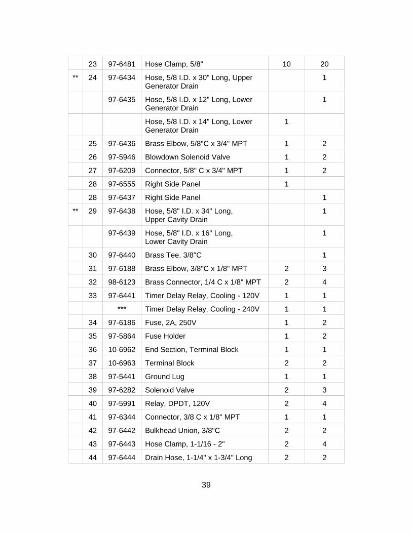
23 97-6481 Hose Clamp, 5/8" 10 20
** 24 97-6434 Hose, 5/8 I.D. x 30" Long, Upper Generator Drain
1
97-6435 Hose, 5/8 I.D. x 12" Long, Lower Generator Drain
1
Hose, 5/8 I.D. x 14" Long, Lower Generator Drain
1
25 97-6436 Brass Elbow, 5/8"C x 3/4" MPT 1 2
26 97-5946 Blowdown Solenoid Valve 1 2
27 97-6209 Connector, 5/8" C x 3/4" MPT 1 2
28 97-6555 Right Side Panel 1
28 97-6437 Right Side Panel 1
** 29 97-6438 Hose, 5/8" I.D. x 34" Long, Upper Cavity Drain
1
97-6439 Hose, 5/8" I.D. x 16" Long, Lower Cavity Drain
1
30 97-6440 Brass Tee, 3/8"C 1
31 97-6188 Brass Elbow, 3/8"C x 1/8" MPT 2 3
32 98-6123 Brass Connector, 1/4 C x 1/8" MPT 2 4
33 97-6441 Timer Delay Relay, Cooling - 120V 1 1
*** Timer Delay Relay, Cooling - 240V 1 1
34 97-6186 Fuse, 2A, 250V 1 2
35 97-5864 Fuse Holder 1 2
36 10-6962 End Section, Terminal Block 1 1
37 10-6963 Terminal Block 2 2
38 97-5441 Ground Lug 1 1
39 97-6282 Solenoid Valve 2 3
40 97-5991 Relay, DPDT, 120V 2 4
41 97-6344 Connector, 3/8 C x 1/8" MPT 1 1
42 97-6442 Bulkhead Union, 3/8"C 2 2
43 97-6443 Hose Clamp, 1-1/16 - 2" 2 4
44 97-6444 Drain Hose, 1-1/4" x 1-3/4" Long 2 2

40
45 97-6445 Drain Tube Assembly 1 2
46 97-5702 Cord Set, 120V 1 1
47 97-6418 Generator Tank, Lower 1
48 97-6419 High Limit Thermostat 1 2
** 49 97-5948 Liquid Level Control, 10K OHM 1 2
Liquid Level Control, 1M OHM (Optional)
1 4
50 97-5701 Transformer, 120-24V 1 2
51 97-6187 Standby Thermostat 1 2
52 97-5572 Ignition Module 1 2
53 97-5992 Relay SPDT, 120V 1 2
54 97-6190 Buzzer 1 2
55 97-6420 Brass Street Elbow, 3/8" FPT x 1/4" MPT
2 4
56 97-6421 Brass Hose Barb, 5/8" x 3/8" MPT 2 4
57 97-6422 Brass Hose Barb, 5/8" x 1/2" MPT 1 2
58 97-6423 Steam Diverter Hose, 5/8 I.D. x O.D. x 11-1/4" LG.
2 4
59 08-6464 Timer, 60 Minutes, 120V 1 2
** 60 97-6424 Upper Delime Hose, 5/8" I.D. x 22" Long
1 1
97-6425 Lower Delime Hose, 5/8" I.D. x 37" Long
1
61 97-6426 Brass Hose Barb, 5/8" x 3/4" MPT 1 2
62 97-6203 Brass Tee, 3/4" 1 2
63 97-6204 Brass Close Nipple, 3/4" 1 2
64 97-6202 Brass Elbow, 3/4" 1 2
65 97-6368 Relief Valve Extension 1 2
66 97-6427 Top Panel 1
66 97-6560 Top Panel 1
67 97-6428 Brass Nipple, 3/4" x 5-1/2" 1 2
68 97-6219 Relief Valve, 5 PSI 1 2

41
69 91-7594 Reducing Elbow Assembly 1 2
91-7765 Clean Port Plug 1 2
69 08-7511 “O” Ring 1 2
70 97-6372 Probe - High Level 1 2
71 97-6213 Probe - Low Level 1 2
72 97-6212 Probe - Low Level Cut Off 1 2
73 08-6502 Pressure Switch 1 2
74 97-6559 Generator Tank, Top 1 1
75 97-6446 Tubing, Pressure Switch, 1/4" I.D. x 8" Long
1 2
76 97-6447 Brass Hose Barb, 1/4" x 1/8 MPT 2 4
77 97-6448 Pressure Switch Bracket 1 2
78 08-5015 Vacuum Breaker 1 2
79 97-6449 Tubing, Vacuum Break, 1/4" I.D. x 2" Long
1 2
80 97-6450 Brass Extruded Street Tee, 1/8" FPT
1 2
82 97-6452 Brass Bushing, NPT, 1/4" to 1/8" 1 2
83 97-6453 Brass Bushing, NPT,1/2" to 1/4" 1 2
84 97-6454 Brass Locknut, 1/2" NPT 1 2
85 10-4586 Sealing Nut, 1/2" NPT 1 2
86 97-6455 Timer Delay Relay, Operating - 120V
1 2
*** Timer Delay Relay, Operating - 240V (EXPORT)
1 2
* NOT SHOWN ** SELECT AS REQUIRED. *** CONTACT FACTORY

42
FIGURE 2

43
FIGURE 2
QUANTITY ITEM
MF
PART NO. DESCRIPTION
ETP-5G ETP-10G
1. 97-6463 Upper Gas Flex Tube, 5/8", O.D. x 42" Long.
1
2. 97-6457 Gas Supply Pipe Assembly 1 1
3. 97-6458 Bracket 1 1
4. 97-6459 Malleable Iron Tee, 3/4" x 3/4" x 1/2"
1
5. 97-6460 Nipple, 3/4" x 2" Long 1
6. 97-5555 90º Reducing Elbow, 3/4" NPT x 1/2" NPT
1 1
** 7. 97-6461 Gas Valve, Natural Gas 1 2
94-5128 Gas Conversion Kit, Natural to LP 1 2
97-6462 Gas Valve, LP Gas 1 2
94-5131 Gas Conversion Kit, LP to Natural 1 2
8. 98-6109 Close Nipple, 1/2" 1 2
9. 98-6122 Union Elbow, 1/2" 1 2
10 97-6532 Lower Gas Flex Tube, 5/8" O.D. x 24" Long
1 1
11 97-6464 Hex Screw, 8 - 32 x 1/4" 4 8
** 12 97-6244 Pilot Burner, LP Gas 1 2
97-6465 Pilot Burner, Natural Gas 1 2
13 97-6245 Burner Mounting Bracket 1 2
14 97-6466 Machine Screw, 10 - 32 x 3/8" 2 4
15 97-6467 Machine Screw, 10 - 32 x 1/4" 2 4
16 97-6242
Spark Electrode 1 2
** 17 97-6468 Pilot Tube - Top 1
97-6469 Pilot Tube - Bottom 1
97-6533 Pilot Tube 1

44
18 97-6470 Machine Bolt, 1/4 - 20 x 1/2" 2 4
19 98-6124 Plug, 1/8" NPT 1 2
** 20 97-6247 Manifold, Natural Gas 1 2
** 20 97-6534 Manifold, LP Gas 1 2
* 21 97-6498 Orifice, #53, Natural Gas 4 8
97-6535 Orifice, #64, LP Gas 4 8
** 22 97-6246 Twin Burners, Natural Gas 2 4
97-6536 Twin Burners, LP Gas 2 4
** 23 97-6472 Screw, #6 x 3/8", (Natural Gas Only)
4 8
* NOT SHOWN. ** SELECT AS REQUIRED.

45
FIGURE 3

46
QUANTITY
ITEM
MF
PART
NO.
DESCRIPTION ETP-5G ETP-10G
** 1. 97-6537 Hinge Rod 1 97-6473 Hinge Rod 1
** 2. 97-6538 Cabinet Door Assembly 1
97-6539 Cabinet Door Assembly 1
3. ~NPN~ Flat Washer 1 1
4. 98-3784 Tempering Tank 1 1
5. 97-6421 Brass Hose Barb, 5/8" x 3/8" MPT 5 7
6. 97-6476 Brass Extruded, 90Ε Street Elbow, 3/8" 4 6
7. ~NPN~ Brass Square Head, 3/8" 2
8. 08-5023 Float Switch 1 1
9. 97-6477 Hex Nipple, 3/4" MPT x 1/2" MPT 1 1
10. 97-6210 Drain Valve, Tank 1 1
11. 97-6436 Brass Elbow, 90Ε, 5/8" C x 3/4 MPT 1 1
12 97-6422 Hose Clamp, 5/8 - 1-1/4" 6 6
** 13 97-6439 Hose, 5/8" I.D. x 16" Long 1
97-6480 Hose, 5/8" I.D. x 14" Long 1
13A 97-6480 Hose, 5/8" I.D. x 14" Long 2 2
14. 08-6514 Tank Thermostat, 130ΕF 1 1
15. 97-6482 Brass Bushing, 1/2" MPT to 3/8" FPT 1 1
16. 97-6483 Brass Elbow, 90Ε, 5/8" C x 1/2" FPT 1 1
17. 97-6346 Brass Elbow, 90Ε, 3/8" C x 3/8" MPT 1 1
18. 97-6484 Vent 1 1
** 19. 97-6415 Bullet Leg 2 2

47
* 97-6406 Swivel Caster, 5", c/w Brake, Optional 2 2
** 20. 97-6486 Adjustable Flanged Foot 2 2
* 97-6561 Swivel Caster, 5", Optional 2 2
21. 97-6487 Pan Slot Head Screws, #6-32 UNC x 3/8" Long 4 4
22. 97-6488 Spring Lock Washer, #6 4 4
23. 97-6489 Magnetic Catch 1 1
24. 97-6490 Magnetic Catch Plate 1 1
25. 97-6540 Manifold Assembly with Check Valve and Tee Fitting 1 1
26. 97-6541 Elbow, 3/8" C to 3/8" MPT, Nylon 1 1
27. 97-6542 Bushing, 3/4" to 3/8", Nylon 2 2
28. 97-6543 Bushing, 3/4" to 1/2", Nylon 1 1
29. 97-6544 Nipple, 1/2" NPT, Nylon 2 2
30. 97-6545 Reducing Elbow, 3/4" to 1/2", Brass 1 1
31. 97-6546 Nipple, 3/4" NPT, Nylon 2 2
32. 08-8053 Check Valve, Nylon 1 1
33. 97-6547 Connector, 3/8" C to 3/8" MPT, Nylon 1 1
34. 97-6548 Tubing, 3/8" O.D., x 18" Long, Nylon 1
34A ~NPN~ Tubing, 3/8" O.D. x 30" Long, Nylon 1 1
35. 97-6549 Sleeve, 3/8", Brass 2 2
36. 97-6550 Connector, 3/8" C to 3/8" Nylon 1 1
37. ~NPN~ Tubing, 3/8" O.D. x 8" Long, Copper 1 1
38. 08-8020 Filter, Large (* See Item 42). 1 1
39. 08-8008 Filter, Small, Scale Inhibitor (* See Item 42) 1 1
40. 08-8007 Meter 1 1
41. 97-6411 Drain Collector 1 1
42. 08-8052 * Kit, Filter Replacement Cartridges 1 1 ** SELECT AS REQUIRED. * NOT SHOWN