Installation and Operation Manual - AEF Salesaefsales.com/docs/manuals/APS-4C.manual.pdfModel...
31
MANUAL 22862 rev A 03/08 (800) 234-4239 http://www.networketi.com Environmental Technology, Inc. Environmental Technology, Inc. 1850 N Sheridan Street South Bend, Indiana 46628 (574) 233-1202 or (800) 234-4239 FAX (574) 233-2152 or (888) 234-4238 http://www.networketi.com/ We Manage Heat ® ® Automatic Snow/Ice Melting System Control Panel MODEL APS ® –3C SNOW SWITCH ® Automatic Snow/Ice Melting System Control Panel MODEL APS ® –4C SNOW SWITCH ® Modular Snow/Ice Heater Control System MODEL SC ™ –40C SATELLITE CONTACTOR Installation and Operation Manual
Transcript of Installation and Operation Manual - AEF Salesaefsales.com/docs/manuals/APS-4C.manual.pdfModel...

MA
NU
AL
22862 rev A 03/08 (800) 234-4239 http://www.networketi.com Environmental Technology, Inc.
Environmental Technology, Inc.1850 N Sheridan StreetSouth Bend, Indiana 46628(574) 233-1202 or (800) 234-4239FAX (574) 233-2152 or (888) 234-4238http://www.networketi.com/
We Manage Heat ®
® Automatic Snow/Ice Melting System Control PanelMODEL APS®–3C SNOW SWITCH®
Automatic Snow/Ice Melting System Control PanelMODEL APS®–4C SNOW SWITCH®
Modular Snow/Ice Heater Control SystemMODEL SC™–40C SATELLITE CONTACTOR
Installation and Operation Manual

Model APS–3C, APS–4C, SC–40C
22862 rev A 03/08(800) 234-4239http://www.networketi.com2 of 31 Environmental Technology, Inc.

Model APS–3C, APS–4C, SC–40C
22862 rev A 03/08 (800) 234-4239 http://www.networketi.com 3 of 31Environmental Technology, Inc.
SafetyMake all electrical connections in compliance with the National Electric Code
(NFPA 70) and local electrical code. If you have questions concerning the installation or application, contact Customer Service.
Additional InformationMore information is regularly made available through our website,
www.networketi.com. Please visit us online for datasheets, manuals, white papers, technical articles and more. The most current and up to date version of this and every other manual for our products can be found in Acrobat (pdf) format to view online or to print. This is to assist you in installing and using our products to the best effect possible. If you have any comments about this or any other material from Environmental Technology please contact us.
Contacting Environmental TechnologyFor assistance, contact Customer Service. Offi ce hours are 8:00 AM until 5:00
PM ET.Voice: (800) 234.4239 (USA and Canada) or (574) 233.1202 (elsewhere)Fax: (888) 234.4238 (USA and Canada) or (574) 233.2152 (elsewhere)E-mail: [email protected] Mail: Environmental Technology, Inc. 1850 North Sheridan Street South Bend, IN 46628
CL1.3125"(33mm)
CL
2.00"(51mm)
2.00"(51mm)
11.500"(292mm)
2.3125"(59mm)
9.125"(232mm)
6.562"(167mm)
1 x 1-1/16" (27mm) Conduit Entry
2 x 1-11/16" (43mm)Conduit Entry
TEST
RESET
GFEP
TEST
Figure 1: APS–4C dimensional

Model APS–3C, APS–4C, SC–40C
22862 rev A 03/08(800) 234-4239http://www.networketi.com4 of 31 Environmental Technology, Inc.
General
Introduction
The APS “C” Series Snow Switch Control Panels, when used with compatible sensors, automatically controls snow and ice melting systems, ensuring complete snow and ice melting at minimum operating costs. Typical applications include pavement, sidewalk, loading dock, roof, gutter and down spout snow/ice melting.
The APS “C” Series continues the APS family of control panels with the APS–3C Control Panel, the APS–4C Control Panel and the SC–40C Satellite Contactor. All three models improve on and extend the features of previous models while maintaining backwards compatibility. The new APS “C” Series models are interchangeable with earlier APS models to ensure the continued long life of existing systems.
The APS “C” Series offers voltage options from 120 VAC up to 600 VAC. The APS–3C is available for 120 and 208-240 VAC and is optimized for inductive loads up to 24 amps, ideal for use in hydronic systems or with customer systems that provide a relay interface. The APS–4C and the SC–40C are available for 208 VAC through 600VAC and are optimized for resistive loads up to 50 amps, with integrated ground fault equipment protection (GFEP).
All of the APS “C” Series models provide a relay closure interface for use with energy management computers (EMC). This feature can also be used for general purpose remote control and annunciation and other advanced applications. Simple remote control features are also provided by the RCU–3 Remote Control for the APS–3C and the RCU–4 Remote Control for the APS–4C and SC–40C.
All sensor and communications wiring is NEC Class 2. This simplifi es installation while enhancing fi re and shock safety. The APS–3C and APS–4C can interface up to six sensors from the CIT–1 product family. More sensors provide superior performance by better matching the controller to site performance requirements. (The SC–40C does not make use of snow/ice sensors but rather is notifi ed of snow conditions by the master APS in the system.)
Environmental InterfacesThe APS “C” Series determines when to start heater operation by monitoring
the signals produced by up to six customer supplied environmental sensors paralleled together using a three-wire bus. Available sensors include:
• SIT–6E Pavement Mounted Snow and Ice Sensor• CIT–1 Aerial Snow and Ice Sensor• GIT–1 Gutter Snow and Ice SensorWhen used either alone or in combination, these sensors accurately determine
whether or not snow and ice melting is required. This data is communicated back to either an APS–3C or APS–4C control.
Sensors measure ambient temperature and detect moisture, in any form. Snow, sleet, freezing rain, etc. is assumed if moisture is present at temperatures below 38°F (3.33°C). Beginning heater operation at temperatures slightly above freezing is essential to meeting customer expectations. It takes a long time for snow to melt at 34°F.
Using several sensors improves snow melting effectiveness by compensating for environmental variations. Consider a typical pavement snow and ice melting system. Vehicular and pedestrian traffi c in commercial environments often expose the pavement to tracked slush and blowing or drifting snow. Since re-freezing could create a hazardous situation, these hazards must be cleared. The solution is to combine several SIT–6E pavement sensors in expected pedestrian and vehicular pathways and a CIT–1 placed high in an open, unobstructed location where it is exposed to falling snow. One or more additional SIT–6E pavement sensors may need to be used in areas subject to drifting and blowing snow and/or melt water run off

Model APS–3C, APS–4C, SC–40C
22862 rev A 03/08 (800) 234-4239 http://www.networketi.com 5 of 31Environmental Technology, Inc.
and refreezing.The fi rst sensor detecting freezing precipitation calls for snow melting. The
last sensor clearing of frozen precipitation signals the APS Control Panel that heating is no longer required.
Sensors employ a heated interdigitated grid for moisture detection. Heat melts frozen precipitation to form water which is a better conductor of electricity. Circuits detect water as a change in resistance between the fi ngers of the interdigitated grid. The temperature of the moisture sensor is regulated electronically.
Each sensor has its own microcontroller for signal processing, logic and control. This enables the use of a simple 3-wire bus to connect sensors with the control. Extension wire function and colors follow:
• Supply (Red) • Signal (White)• Ground (Black)The supply voltage is nominally 24 VAC. The signal is inverted. That is, snow
produces a ground and its absence produces 24 VAC rectifi ed.Sensors are wired together in parallel in a “wired OR” confi guration. That is,
red to red, white to white and black to black. When several sensors are connected in parallel, any sensor asserting a ground on the signal conductor enables snow melting heater operation. No ground on the signal line indicates the absence of snow.
APS “C” series models include a temperature sensor for measuring pavement slab or ambient air temperature. Its signal is used to provide an adjustable high limit thermostat function. This feature is essential when using a potentially high temperature heater such as MI cable.
High Limit ThermostatThe calibrated 40°F to 90°F (4°C to 32°C) high limit thermostat prevents
excessive temperatures when using constant wattage and MI heaters. It also permits safe testing at outdoor temperatures too high for continuous heater operation. The temperature sensor is included.
There are two DIP switch confi gurable operation modes for the high limit thermostat. The factory default operation mode uses the high limit thermostat as a slab temperature regulator, preventing heater operation at temperatures above the set HIGH TEMPERATURE LIMIT. The optional operation mode uses the high limit thermostat as an ambient air sensor, preventing heater operation at temperatures above the set HIGH TEMPERATURE LIMIT until the temperature comes back within limits.
The details of operation in each mode are as follows:
Slab Regulating Thermostat Mode• High temperature causes unit to turn off heaters, if running, and to ignore
any call for heater operation from the panel, RCU or EMC.• High temperature continues any hold-on cycle that was initiated before the
high temperature condition. If the slab temperature drops within limits during the hold-on time the heater will be turned back on.
• In a high temperature condition an APS will still initiate operation of connected SC–40C contactor(s).
• The HEATER CYCLE functions normally.
Ambient Temperature Thermostat Mode• High temperature causes unit to turn off heaters, if running, and to ignore
any call for heater operation from the panel, RCU or EMC.• High temperature cancels any hold-on cycle that was initiated before the
high temperature condition.

Model APS–3C, APS–4C, SC–40C
22862 rev A 03/08(800) 234-4239http://www.networketi.com6 of 31 Environmental Technology, Inc.
• In a high temperature condition an APS will not initiate operation of connected SC–40C contactor(s).
• If the HEATER CYCLE switch is operated in a high temperature condition the heater(s) will be turned on for a maximum of 30 seconds. A new HEATER CYCLE can not be initiated for another two minutes after that.
Hold-on TimeThe adjustable hold-on timer provides three functions affecting heater
operation. The hold-on timer is used to continue heater operation, to manually operate heaters or to provide a limited heater cycle for testing.
During normal operation the hold-on timer continues heater operation for an adjustable time period of up to 10 hours after snow stops. The additional operating time compensates for the fact that there may be insuffi cient power to both melt the snow as it falls and evaporate the resultant melt water.
After normal operation has ended the hold-on timer provides a method for clearing tracked or drifting snow that did not fall on a sensor. This can be accomplished by either increasing the hold-on or by manually toggling the heaters on for the hold-on time independent of environmental conditions.
Lastly, the hold-on timer provides a method of safe heater testing that is independent of environmental conditions. The High Limit Thermostat ensures that this is the case. In ambient mode, at ambient temperatures above the high limit, the manual hold-on time is reduced to 30 seconds. In pavement mode, at pavement temperatures above the high limit, heaters are disabled.
Initial SettingsWhen fi rst placing the system in service, the hold-on time should be set to an
initial value. Three to fi ve hours is suggested as a starting point. If the heaters turn off before the snow is completely cleared and the melt water evaporated, increase the hold-on time by an hour or two. If the heaters operate for several hours after the pavement is clear and dry, decrease the hold-on time by an hour. Continue this process until satisfactory performance is achieved.
The small amount of energy wasted by a slightly excessive hold-on time is secondary to complete snow clearing and melt water evaporation. Incomplete operation is not desirable since this can result in re-freezing melt water which creates a slippery ice fi lm.
If The System Turns Off Too Soon
If the system turns off before the pavement is clear and dry, toggle the heaters on for the hold-on using the HOLD-ON switch on the front panel of the control. Repeat as many times as is necessary until the pavement is clear and dry. If the heaters remain operating after the pavement is clear and dry, terminate the hold-on cycle with the HOLD-ON switch. Normal operation resumes if it starts snowing during hold-on.
Ground Fault Equipment Protection (GFEP) OperationGFEP operates in the event of a deicing heater failure indicated by excessive
leakage current to ground. The leakage current equals the difference between the line and return currents fl owing through the heaters. A precision current transformer measures the difference in currents. If the difference exceeds 30 mA, the heater contactor drops out. This removes heater power, thus eliminating potential fi re and electric shock hazards.
Sometimes longer length and/or higher voltage heaters cause nuisance GFEP operation. This is true even though the heaters are operating properly. Increasing
Model APS–3C, APS–4C, SC–40C
22862 rev A 03/08 (800) 234-4239 http://www.networketi.com 7 of 31Environmental Technology, Inc.
the GFEP operating current can correct this problem. A DIP switch can increase the operating current from a default value of 30 to 60 or 120 mA.
Restoring heater operation requires operating the RESET switch on the front panel of the control. This starts a sequence of events beginning with testing the GFEP to make certain that it operates properly. If it is inoperative, the GFEP condition persists. Otherwise, the heater contactor is energized. If excessive ground current fl ows, the GFEP drops the contactor and waits for operation of the RESET switch. Otherwise, the contactor is operated only if there is a call for heat.
The GFEP checks itself and the deicing heaters every 24 hours independent of environmental conditions. Operating the TEST switch on the front panel performs the same function. In addition, the GFEP function is tested each time the heater control contactor operates.
Energy Management Computer (EMC) InterfaceThe APS “C” Series interfaces an EMC via relays. Inputs from the EMC include
OVERRIDE ON which causes heater operation and OVERRIDE OFF which inhibits heater operation. These functions are independent of weather conditions and the status of the hold-on timer. The interface provides fi ve system status contact closures for the EMC including SUPPLY, SNOW, HEATER, ALARM and TEMPERATURE LIMIT.
Absent signals from the EMC, the APS control panel controls the heaters based on environmental conditions. Automatic snow melting control is the default condition of the system.
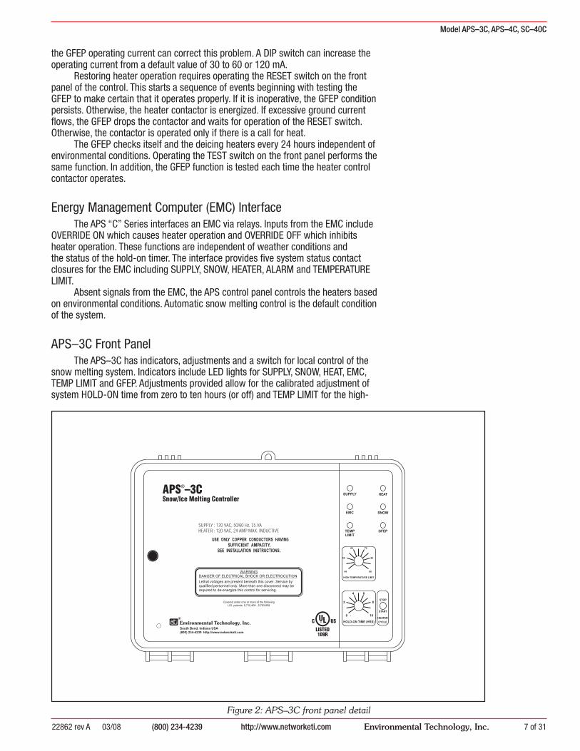
APS–3C Front PanelThe APS–3C has indicators, adjustments and a switch for local control of the
snow melting system. Indicators include LED lights for SUPPLY, SNOW, HEAT, EMC, TEMP LIMIT and GFEP. Adjustments provided allow for the calibrated adjustment of system HOLD-ON time from zero to ten hours (or off) and TEMP LIMIT for the high-
Figure 2: APS–3C front panel detail
Model APS–3C, APS–4C, SC–40C
22862 rev A 03/08(800) 234-4239http://www.networketi.com8 of 31 Environmental Technology, Inc.
limit temperature adjustment with a range of 40° to 90°F (4° to 32°C). The HEATER TOGGLE switch allows for the starting and stopping of a manual HEATER CYCLE.
Figure 2 shows the APS–3C front panel layout.
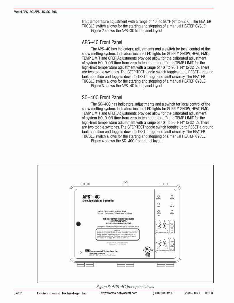
APS–4C Front PanelThe APS–4C has indicators, adjustments and a switch for local control of the
snow melting system. Indicators include LED lights for SUPPLY, SNOW, HEAT, EMC, TEMP LIMIT and GFEP. Adjustments provided allow for the calibrated adjustment of system HOLD-ON time from zero to ten hours (or off) and TEMP LIMIT for the high-limit temperature adjustment with a range of 40° to 90°F (4° to 32°C). There are two toggle switches. The GFEP TEST toggle switch toggles up to RESET a ground fault condition and toggles down to TEST the ground fault circuitry. The HEATER TOGGLE switch allows for the starting and stopping of a manual HEATER CYCLE.
Figure 3 shows the APS–4C front panel layout.
SC–40C Front PanelThe SC–40C has indicators, adjustments and a switch for local control of the
snow melting system. Indicators include LED lights for SUPPLY, SNOW, HEAT, EMC, TEMP LIMIT and GFEP. Adjustments provided allow for the calibrated adjustment of system HOLD-ON time from zero to ten hours (or off) and TEMP LIMIT for the high-limit temperature adjustment with a range of 40° to 90°F (4° to 32°C). There are two toggle switches. The GFEP TEST toggle switch toggles up to RESET a ground fault condition and toggles down to TEST the ground fault circuitry. The HEATER TOGGLE switch allows for the starting and stopping of a manual HEATER CYCLE.
Figure 4 shows the SC–40C front panel layout.
TEST
RESET
GFEP
TEST
Figure 3: APS–4C front panel detail

Model APS–3C, APS–4C, SC–40C
22862 rev A 03/08 (800) 234-4239 http://www.networketi.com 9 of 31Environmental Technology, Inc.
TEST
RESET
GFEP
TEST
RCU–3 Remote Control Unit
The RCU–3 Remote Control Unit is used with the APS–3C. It adds remote control and status display to the APS–3C control at a location convenient to personnel capable of observing snow melting system operation.
Snow, slush or ice, either alone or in combination, must contact at least one sensor to start melting. Heater operation continues until all sensors are dry. Depending up the rate of fall, snow density, wind velocity, power density and other factors, heater operation must continue for a period of time after the last sensor dries off. Slush tracked by vehicle and pedestrian traffi c along with blowing and drifting snow are problems that are hard to predict.
The cycle timer in the APS–3C begins when the last sensor dries off and continues for an adjustable period of up to 10 hours to keep the heaters operational until the pavement is completely dry. Otherwise, residual water could re-freeze and create a hazardous condition.
The RCU–3 provides a two, four, six or eight hour CYCLE TIME adjustment that is independent of the cycle time in the APS–3C. This allows treatment of the condition requiring an additional heater cycle as the exception rather than the rule in order to minimize energy use.
Operating the HEATER CYCLE switch operates heaters for the CYCLE TIME which is normally set to 2 hours. Operating the HEATER CYCLE switch during the cycle time stops the timer. If the pavement or ambient temperature exceeds the APS–3C HIGH LIMIT TEMPERATURE setting, the heater duty cycle is reduced or disabled to prevent overheating.
Status indicators include SUPPLY and HEAT. These perform the same functions as those on the APS–3C front panel.
Figure 5 shows the RCU–3 layout.
Figure 4: SC–40C front panel detail

Model APS–3C, APS–4C, SC–40C
22862 rev A 03/08(800) 234-4239http://www.networketi.com10 of 31 Environmental Technology, Inc.
RCU–4 Remote ControlThe RCU–4 Remote Control Unit is used with the APS–4C and SC–40C. It adds
remote control and status display to the APS–4C or SC–40C controls at a location convenient to personnel capable of observing snow melting system operation.
Snow, slush or ice, either alone or in combination, must contact at least one sensor to start melting. Heater operation continues until all sensors are dry. Depending on the rate of fall, snow density, wind velocity, power density and other factors, heater operation must continue for a period of time after the last sensor dries off. Slush tracked by vehicle and pedestrian traffi c along with blowing and drifting snow are problems that are hard to predict.
The cycle timer in the APS–4C/SC–40 begins when the last sensor dries off and continues for an adjustable period of up to 10 hours to keep the heaters operating until the pavement is completely dry. Otherwise, residual water could re-freeze and create a hazardous condition.
The RCU–4 provides a two, four, six or eight hour CYCLE TIME adjustment that is independent of the cycle times in the APS–4C and SC–40C. This allows treatment of the condition requiring extra heating as the exception rather than the rule thus minimizing energy.
Operating the HEATER CYCLE switch operates heaters for the CYCLE TIME which is normally set to 2 hours. Operating the HEATER CYCLE switch during the cycle time stops the timer. If the pavement or ambient temperature exceeds the APS–4C or SC–40C HIGH LIMIT TEMPERATURE setting, the heater duty cycle is reduced or disabled to prevent overheating.
Status indicators include SUPPLY and HEAT. These perform the same functions as those on the APS–4C front panel.
The GFEP switch performs the same functions and operates in the same manner as the ones on the front panels of the APS–4C and SC–40C. In the event of an unacknowledged GFEP, the HEAT indicator fl ashes.
Figure 5 shows the RCU–4 layout.
2
4 6
8
®SOUTH BEND, INDIANA USA
HEAT SUPPLY
HEATER CYCLE
RCU –321357
E NV IR O NME NT A L T E C H NO L O G Y , INC .
CYCLE TIME(HRS)
TM
2
4 6
8
®SOUTH BEND, INDIANA USA
HEAT SUPPLY
E NV IR O NME NT A L T E C H NO L O G Y , INC .
CYCLE TIME(HRS)
TMRCU –421358
HEATERCYCLE
GFEPTEST/RESET
Figure 5: RCU–3 and RCU–4
Model APS–3C, APS–4C, SC–40C
22862 rev A 03/08 (800) 234-4239 http://www.networketi.com 11 of 31Environmental Technology, Inc.
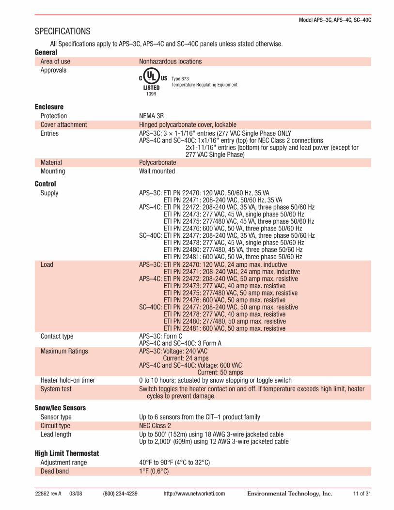
SPECIFICATIONSAll Specifi cations apply to APS–3C, APS–4C and SC–40C panels unless stated otherwise.
General
Area of use Nonhazardous locationsApprovals
109R
Type 873Temperature Regulating Equipment
Enclosure
Protection NEMA 3RCover attachment Hinged polycarbonate cover, lockableEntries APS–3C: 3 × 1-1/16" entries (277 VAC Single Phase ONLY
APS–4C and SC–40C: 1x1/16" entry (top) for NEC Class 2 connections 2x1-11/16" entries (bottom) for supply and load power (except for
277 VAC Single Phase)Material PolycarbonateMounting Wall mounted
Control
Supply APS–3C: ETI PN 22470: 120 VAC, 50/60 Hz, 35 VA ETI PN 22471: 208-240 VAC, 50/60 Hz, 35 VAAPS–4C: ETI PN 22472: 208-240 VAC, 35 VA, three phase 50/60 Hz ETI PN 22473: 277 VAC, 45 VA, single phase 50/60 Hz ETI PN 22475: 277/480 VAC, 45 VA, three phase 50/60 Hz ETI PN 22476: 600 VAC, 50 VA, three phase 50/60 HzSC–40C: ETI PN 22477: 208-240 VAC, 35 VA, three phase 50/60 Hz ETI PN 22478: 277 VAC, 45 VA, single phase 50/60 Hz ETI PN 22480: 277/480, 45 VA, three phase 50/60 Hz ETI PN 22481: 600 VAC, 50 VA, three phase 50/60 Hz
Load APS–3C: ETI PN 22470: 120 VAC, 24 amp max. inductive ETI PN 22471: 208-240 VAC, 24 amp max. inductiveAPS–4C: ETI PN 22472: 208-240 VAC, 50 amp max. resistive ETI PN 22473: 277 VAC, 40 amp max. resistive ETI PN 22475: 277/480 VAC, 50 amp max. resistive ETI PN 22476: 600 VAC, 50 amp max. resistiveSC–40C: ETI PN 22477: 208-240 VAC, 50 amp max. resistive ETI PN 22478: 277 VAC, 40 amp max. resistive ETI PN 22480: 277/480, 50 amp max. resistive ETI PN 22481: 600 VAC, 50 amp max. resistive
Contact type APS–3C: Form CAPS–4C and SC–40C: 3 Form A
Maximum Ratings APS–3C: Voltage: 240 VAC Current: 24 ampsAPS–4C and SC–40C: Voltage: 600 VAC Current: 50 amps
Heater hold-on timer 0 to 10 hours; actuated by snow stopping or toggle switchSystem test Switch toggles the heater contact on and off. If temperature exceeds high limit, heater
cycles to prevent damage.
Snow/Ice Sensors
Sensor type Up to 6 sensors from the CIT–1 product familyCircuit type NEC Class 2Lead length Up to 500' (152m) using 18 AWG 3-wire jacketed cable
Up to 2,000' (609m) using 12 AWG 3-wire jacketed cable
High Limit Thermostat
Adjustment range 40°F to 90°F (4°C to 32°C)Dead band 1°F (0.6°C)
Model APS–3C, APS–4C, SC–40C
22862 rev A 03/08(800) 234-4239http://www.networketi.com12 of 31 Environmental Technology, Inc.
Sensor type Thermistor networkCircuit type NEC Class 2Lead length Up to 500' (152m) using 18 AWG 2-wire jacketed cable
Up to 1,000' (304m) using 12 AWG 2-wire jacketed cable
Energy Management Computer (EMC) Interface
Inputs OVERRIDE ON (10 ma dry switch contact)OVERRIDE OFF (10 ma dry switch contact)
Outputs SUPPLY (10 ma dry switch contact)SNOW (10 ma dry switch contact)HEAT (10 ma dry switch contact)HIGH TEMP (10 ma dry switch contact)ALARM (10 ma dry switch contact)
Environmental
Operating temperature –40°F to 160°F (–40°C to 71°C)Storage temperature –50°F to 180°F (–45°C to 82°C)
Ground Fault Equipment Protection (GFEP)(APS–4C and SC–40C only)
Set point 30 mA (default); 60 mA and 120 mA selectable by DIP switchAutomatic self-test Mode A: Verifi es GFEP function before contactors operate
Mode B: Verifi es GFEP and heaters every 24 hoursManual test/reset Toggle switch provided for this functionMaintenance facility DC output proportional to ground current provided for troubleshooting the heater
system
Communication Bus (SC–40C only)
Number of cascaded units UnlimitedContactor delay 5 secondBus-wire type 3-wire jacketed cableCircuit type NEC Class 2Lead Length Up to 500' (152m) using 18 AWG 3-wire jacketed cable
Up to 1,000' (304m) using 12 AWG 3-wire jacketed cable

Model APS–3C, APS–4C, SC–40C
22862 rev A 03/08 (800) 234-4239 http://www.networketi.com 13 of 31Environmental Technology, Inc.
Operation
APS–3C
The snow melting system can be monitored and controlled either locally from the APS–3C itself or from two remote locations including:
• RCU–3 Remote Control Unit• BEMC
Local Control from the APS–3C
Indicators:• SUPPLY (green) shows that power is present.• SNOW (yellow) shows that there is a snow/ice signal originating from at
least one of the CIT–1, GIT–1 and/or SIT–6E sensors attached to the system.• HEAT (yellow) shows that there is a call for heat. This happens during snow
and for the hold-on time thereafter or when the heater cycle switch is operated.• EMC (yellow) shows that the interfaced Energy Management Computer is
presently overriding local system control.• TEMP LIMIT (red) shows that either the pavement temperature is above
the set HIGH TEMPERATURE LIMIT and there is a call for HEAT or the ambient air temperature is above the set HIGH TEMPERATURE LIMIT. The APS–3C can be confi gured to monitor slab temperature or ambient air temperature but not both.
• GFEP (red, blinking) shows that there is a GFEP condition present on an attached SC–40 Satellite Contactor.
Adjustments:• HOLD-ON TIME adjustment sets the time that heaters operate after snow
stops. Doing this is necessary to make certain the pavement dries before heating ceases. This prevents refreezing. Try an initial setting of 3-5 hours. Increase, if necessary. Reduce with care since energy savings are being traded for an increased likelihood of refreezing.
• HIGH-LIMIT TEMPERATURE adjustment sets the maximum deicing temperature.
Switches:• HEATER CYCLE switch momentarily toggled down will start a manual heater
cycle for the set HOLD-ON TIME or restart the HEATER CYCLE if on was already in progress. Momentarily toggled up will cancel a heater cycle if one is in progress.
Remote Control from the RCU–3
Indicators:• SUPPLY (green) shows that power is present.• HEAT (yellow) shows that there is a call for heat. This happens during snow
and for the hold-on time thereafter or when the heater cycle switch is operated.Adjustments:• CYCLE TIME adjustment sets the time heaters will operate when HEATER
CYCLE switch is momentarily depressed at the RCU–3.

Model APS–3C, APS–4C, SC–40C
22862 rev A 03/08(800) 234-4239http://www.networketi.com14 of 31 Environmental Technology, Inc.
Switches:• HEATER CYCLE switch momentarily depressed will start a manual heater
cycle for the set CYCLE TIME. Momentarily depressed while heaters are being operated by a hold-on timer or during manual heater cycle will end the heater cycle. Heater operation during snow conditions cannot be canceled in this manner.
Remote Control form the EMC InterfaceThe EMC interface is identical on all of the APS “C” Series models. Please see
the EMC section of the manual for interface details.
APS–4C and SC–40CThe snow melting system can be monitored and controlled either locally from
the APS–4C itself or from two remote locations connected to the APS control panel including:
• RCU–4 Remote Control Unit• EMCControl initiated from an SC–40C is local to the heater(s) connected to that
panel and will not affect the operation of heaters attached to the APS control panel or other SC–40C contactors in the system. This includes remote control operation from an RCU–4 or EMC connected to an SC–40.
Local Control for the APS–4C or SC–40C
Indicators:• SUPPLY (green) shows that power is present.• SNOW (yellow) shows that there is a snow/ice signal originating from at
least one of the connected CIT–1, GIT–1 and/or SIT–6E sensors attached to the system.
• HEAT (yellow) shows that there is a call for heat. This happens during snow and for the hold-on time thereafter or when the heater cycle switch is operated.
• EMC (yellow) shows that the interfaced Energy Management Computer is presently overriding local system control.
• TEMP LIMIT (red) shows that either the pavement temperature is above the set HIGH TEMPERATURE LIMIT and there is a call for HEAT or the ambient air temperature is above the set HIGH TEMPERATURE LIMIT. The APS–4C can be confi gured to monitor ambient air temperature or slab temperature but not both.
• GFEP (red) shows that there is a GFEP condition present on the local APS–4C Control Panel or SC–40 Satellite Contactor.
GFEP (red, blinking) shows that there is a GFEP condition present on an attached SC–40 Satellite Contactor.
Adjustments:• HOLD-ON TIME adjustment sets the time that heaters operate after snow
stops. Doing this is necessary to make certain the pavement dries before heating ceases. This prevents refreezing. Try an initial setting of 3-5 hours. Increase, if necessary. Reduce with care since energy savings are being traded for an increased likelihood of refreezing.
• HIGH-LIMIT TEMPERATURE adjustment sets the maximum deicing temperature.
Switches:• GFEP TEST switch momentarily toggled down will start a test of the ground
Model APS–3C, APS–4C, SC–40C
22862 rev A 03/08 (800) 234-4239 http://www.networketi.com 15 of 31Environmental Technology, Inc.
fault circuitry of that APS–4C or SC–40C. Momentarily toggled up will RESET a ground fault condition at that APS–4C or SC–40C.
• HEATER CYCLE switch momentarily toggled down will start a manual heater cycle for the set HOLD-ON TIME or restart the HEATER CYCLE if on was already in progress. Momentarily toggled up will cancel a heater cycle if one is in progress.
Remote Control from the RCU–4
Indicators:• SUPPLY (green) shows that power is present.• HEAT (yellow) shows that there is a call for heat. This happens during snow
and for the hold-on time thereafter or when the heater cycle switch is operated.
Adjustments:• CYCLE TIME adjustment sets the time heaters will operate when HEATER
CYCLE switch is momentarily depressed at the RCU–4.
Switches:• GFEP TEST/RESET switch momentarily depressed when there is no ground
fault condition will start a test of the ground fault circuitry of that APS–4C or SC–40C. Momentarily depressed when there is a ground fault condition at the attached APS–4C or SC–40C will RESET a ground fault condition at that APS–4C or SC–40C and start a test of the ground fault circuitry of that APS–4C or SC–40C.
• HEATER CYCLE switch momentarily depressed will start a manual heater cycle for the set CYCLE TIME. Momentarily depressed while heaters are being operated by a hold-on timer or during manual heater cycle will end the heater cycle. Heater operation during snow conditions cannot be canceled in this manner.
Remote Control from the EMC InterfaceThe EMC interface is identical on all of the APS “C” Series models. Please see
the EMC section of the manual for interface details.
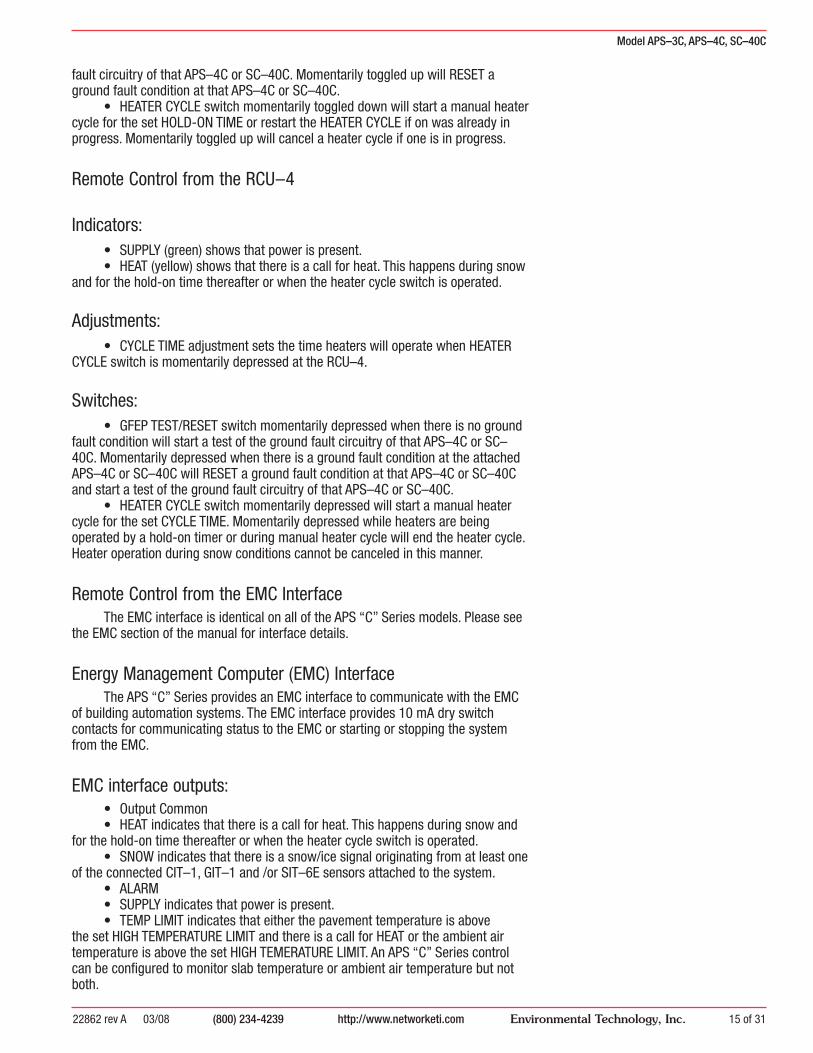
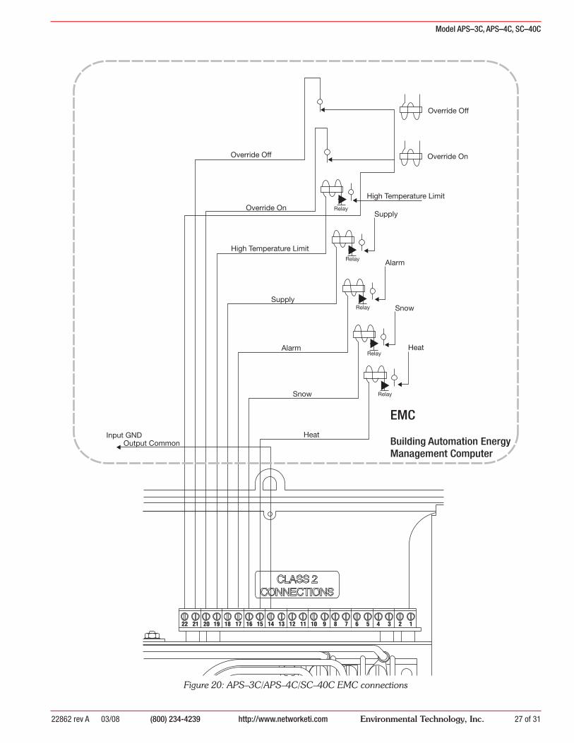
Energy Management Computer (EMC) InterfaceThe APS “C” Series provides an EMC interface to communicate with the EMC
of building automation systems. The EMC interface provides 10 mA dry switch contacts for communicating status to the EMC or starting or stopping the system from the EMC.
EMC interface outputs:• Output Common• HEAT indicates that there is a call for heat. This happens during snow and
for the hold-on time thereafter or when the heater cycle switch is operated.• SNOW indicates that there is a snow/ice signal originating from at least one
of the connected CIT–1, GIT–1 and /or SIT–6E sensors attached to the system.• ALARM• SUPPLY indicates that power is present.• TEMP LIMIT indicates that either the pavement temperature is above
the set HIGH TEMPERATURE LIMIT and there is a call for HEAT or the ambient air temperature is above the set HIGH TEMERATURE LIMIT. An APS “C” Series control can be confi gured to monitor slab temperature or ambient air temperature but not both.
Model APS–3C, APS–4C, SC–40C
22862 rev A 03/08(800) 234-4239http://www.networketi.com16 of 31 Environmental Technology, Inc.
EMC interface inputs:• OVERRIDE ON can be used to override an attached APS “C” Series control in
order to turn heaters on. A normal contact closure will turn on heaters until operation is cancelled. If the EMC cycles the OVERIDE ON relay on and off again within more than 32 milliseconds but less than 300 milliseconds the attached APS “C” Series control will begin a manual heater cycle and run for the HOLD-ON TIME set at the panel.
• OVERRIDE OFF can be used to override an attached APS “C” Series control in order to turn heaters off. A normal contact closure will turn off heaters. If the EMC cycles the OVERIDE OFF relay on and off again within more than 32 milliseconds but less than 300 milliseconds the attached APS “C” Series control will end a manual heater cycle.
Installation
22 21 20 19 18 17 16 15 14 13 12 11 10 9 8 7 6 5 4 3 2 1
ON
OFF
1 2 3 4
Jumper Settings
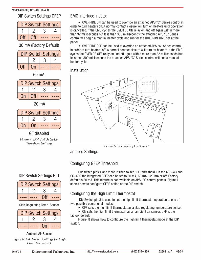
Confi guring GFEP Threshold
DIP switch pins 1 and 2 are utilized to set GFEP threshold. On the APS–4C and SC–40C the integrated GFEP can be set to 30 mA, 60 mA, 120 mA or off. Factory default is 30 mA. This feature is not available on APS–3C control panels. Figure 7 shows how to confi gure GFEP option at the DIP switch.
Confi guring the High Limit Thermostat Dip Switch pin 3 is used to set the high limit thermostat operation to one of
two possible operational modes:• OFF sets the high limit thermostat as a slab regulating temperature sensor.• ON sets the high limit thermostat as an ambient air sensor. OFF is the
factory default.Figure 8 shows how to confi gure the high limit thermostat mode at the DIP
switch.
DIP Switch Settings1 3 42
Off Off ---- ----
30 mA (Factory Default)
DIP Switch Settings1 3 42
Off On ---- ----
60 mA
DIP Switch Settings1 3 42On Off ---- ----
120 mA
DIP Switch Settings1 3 42On On ---- ----
GF disabled
DIP Switch Settings GFEP
Figure 6: Location of DIP Switch
Figure 7: DIP Switch GFEPThreshold Settings
Figure 8: DIP Switch Settings for High Limit Thermostat
DIP Switch Settings HLT
DIP Switch Settings1 3 42
---- ---- Off ----Slab Regulating Temp. Sensor
DIP Switch Settings1 3 42
---- ---- On ----Ambient Air Sensor
Model APS–3C, APS–4C, SC–40C
22862 rev A 03/08 (800) 234-4239 http://www.networketi.com 17 of 31Environmental Technology, Inc.
Factory Use OnlyDIP switch pin 4 is for factory use only. The use of pin 4 except by authorized
personnel may lead to improper operation of the APS–3C, APS–4C or SC–40C.
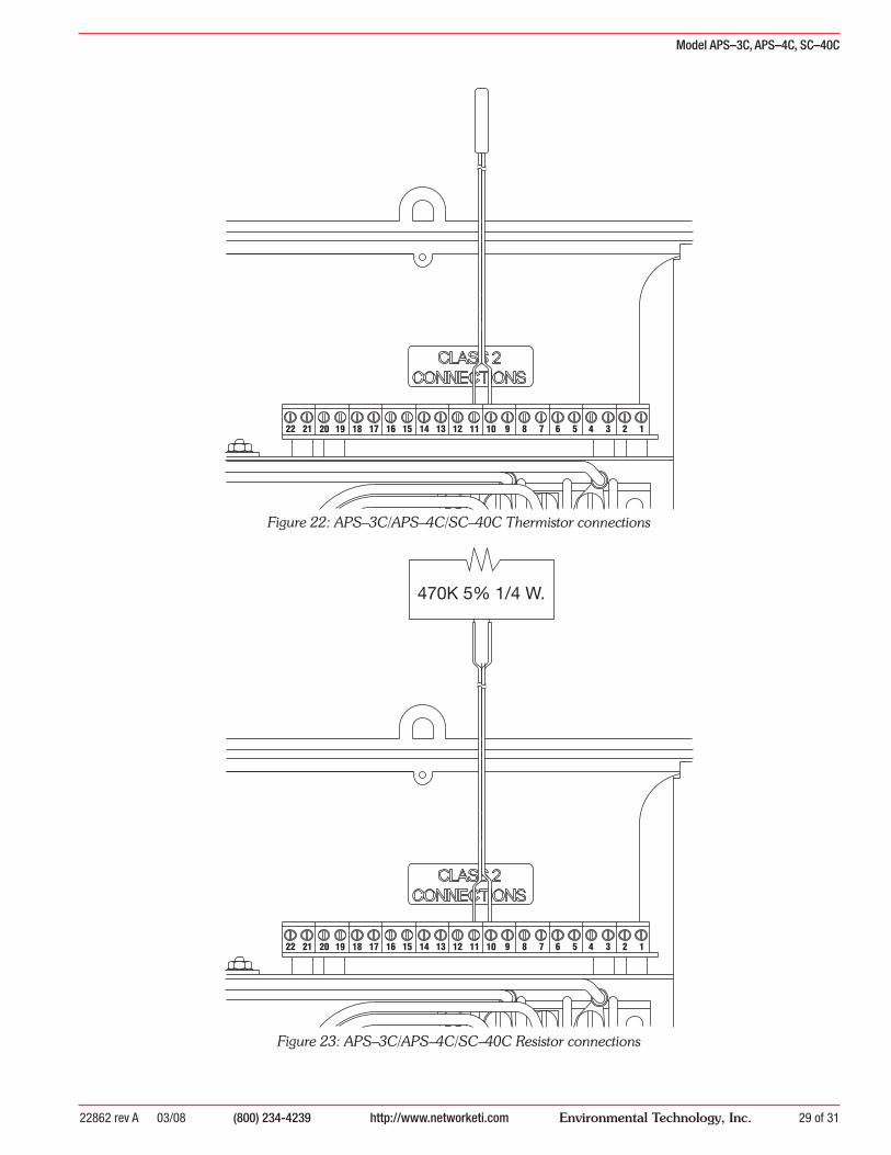
Bypassing the High Limit Temperature Sensor
If, for any reason, you need to operate the system without the High Limit Temperature Sensor (for trouble shooting or while waiting for a replacement sensor) you can temporarily replace the sensor with a 470K resistor. The resistor will allow the system to run as if the sensed temperature was 40°F (4.4°C).
Refer to Figure 23 for placement of resistor.
Reading the GFEP Current
The GFEP current being sensed by an APS–4C or SC–40C can be measured using a standard hand-held digital volt meter (DVM). Attach the DVM (reading DC voltage up to 2 volts) to pins 12 and 13. The DVM reading will be scaled 0.01 VDC= 1 mA. A typical reading then may be 0.3 VDC which would equal a GFEP current of 30 mA.
As long as no ground fault condition exists, the DVM reading will change in real time. In the case of a ground fault condition the reading at the time of the ground fault will be read until GFEP is reset on the panel or until power is cycled.
Refer to Figure 21 for DVM connections.
Model APS–3C, APS–4C, SC–40C
22862 rev A 03/08(800) 234-4239http://www.networketi.com18 of 31 Environmental Technology, Inc.
CLASS 2
LOADN.C.
N.C.
N.O.
N.O.
CONNECTIONS
EQUIPMENTGROUND
SUPPLY
0
2
4 6
8
10
HOLD-ON TIME (HRS)
SUPPLY
EMC
TEMPLIMIT
HEAT
SNOW
GFEP
STAR T
STOP
HEA TERCYCLE
HIGH TEMPERATURE LIMIT
40 90
50
60 70
80
LATCH
UNLATCH
C1
LATCH
UNLATCH
NONC
NONC
G
L1 NL2
SUPPLY120 VAC 50/60 Hz
L1
L2L1
L2
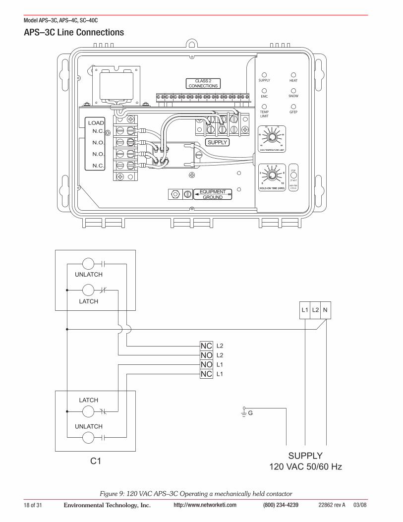
APS–3C Line Connections
Figure 9: 120 VAC APS–3C Operating a mechanically held contactor
Model APS–3C, APS–4C, SC–40C
22862 rev A 03/08 (800) 234-4239 http://www.networketi.com 19 of 31Environmental Technology, Inc.
C2
C1
NONC
NONC
G
L1 NL2
SUPPLY120 VAC 50/60 Hz
L1
L2L1
L2
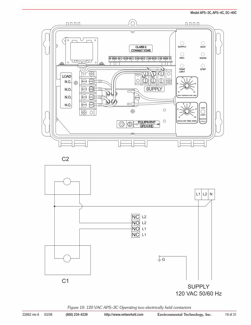
Figure 10: 120 VAC APS–3C Operating two electrically held contactors
0
2
4 6
8
10
HOLD-ON TIME (HRS)
SUPPLY
EMC
TEMPLIMIT
HEAT
SNOW
GFEP
START
STOP
HEATER
CYCLE
HIGH TEMPERATURE LIMIT
40 90
50
60 70
80

Model APS–3C, APS–4C, SC–40C
22862 rev A 03/08(800) 234-4239http://www.networketi.com20 of 31 Environmental Technology, Inc.
CLASS 2
LOADN.C.
N.C.
N.O.
N.O.
CONNECTIONS
EQUIPMENTGROUND
SUPPLY
0
2
4 6
8
10
HOLD-ON TIME (HRS)
SUPPLY
EMC
TEMPLIMIT
HEAT
SNOW
GFEP
START
STOP
HEATERCYCLE
HIGH TEMPERATURE LIMIT
40 90
50
60 70
80
Figure 11: 240 VAC APS–3C Operating mechanically held contactors
C2
LATCH
UNLATCH
C1
LATCH
UNLATCH
NONC
NONC
L1 L2
SUPPLY208 - 240 VAC
50/60 Hz
L1
L2L1
L2
G
NO
CO
NN
EC
TIO
N
Model APS–3C, APS–4C, SC–40C
22862 rev A 03/08 (800) 234-4239 http://www.networketi.com 21 of 31Environmental Technology, Inc.
0
2
4 6
8
10
HOLD-ON TIME (HRS)
SUPPLY
EMC
TEMPLIMIT
HEAT
SNOW
GFEP
START
STOP
HEATER
CYCLE
HIGH TEMPERATURE LIMIT
40 90
50
60 70
80
C2
C1
NONC
NONC
G
L1 L2
L1
L2L1
L2
SUPPLY208 - 240 VAC
50/60 Hz
NO
CO
NN
EC
TIO
N
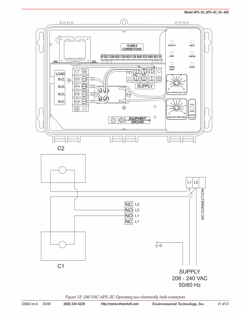
Figure 12: 240 VAC APS–3C Operating two electrically held contactors

Model APS–3C, APS–4C, SC–40C
22862 rev A 03/08(800) 234-4239http://www.networketi.com22 of 31 Environmental Technology, Inc.
HEATER
CLASS 2CONNECTIONS
EQUIPMENTGROUND
0
2
4 6
8
10
HOLD-ON TIME (HRS)
SUPPLY
EMC
TEMPLIMIT
HEAT
SNOW
GFEP
TEST
RESET
START
STOP
HEATER
CYCLE
GFEP
TESTHIGH TEMPERATURE LIMIT
40 90
50
60 70
80
APS–4C/SC–40C22473 (APS–4C 277V 1 PH)22478 (SC–40C 277V 1 PH)
1
Figure 13: APS–4C and SC–40C 277 VAC Single Phase Heater Connect

Model APS–3C, APS–4C, SC–40C
22862 rev A 03/08 (800) 234-4239 http://www.networketi.com 23 of 31Environmental Technology, Inc.
HEATERSUPPL
CLASS 2CONNECTIONS
EQUIPMENTGROUND
0
2
4 6
8
10
HOLD-ON TIME (HRS)
SUPPLY
EMC
TEMPLIMIT
HEAT
SNOW
GFEP
TEST
RESET
START
STOP
HEATER
CYCLE
GFEP
TESTHIGH TEMPERATURE LIMIT
40 90
50
60 70
80
APS–4C/SC–40C22472 (APS–4C 208/240V)22475 (APS–4C 277/480V)22476 (APS–4C 600V)22477 (SC–40C 208/240V)22480 (SC–40C 277/480V)22481 (SC–40C 600V)
Figure 14: APS–4C and SC–40C Three Phase Delta
Model APS–3C, APS–4C, SC–40C
22862 rev A 03/08(800) 234-4239http://www.networketi.com24 of 31 Environmental Technology, Inc.
HEATERSUPPL
CLASS 2CONNECTIONS
EQUIPMENTGROUND
0
2
4 6
8
10
HOLD-ON TIME (HRS)
SUPPLY
EMC
TEMPLIMIT
HEAT
SNOW
GFEP
TEST
RESET
START
STOP
HEATER
CYCLE
GFEP
TESTHIGH TEMPERATURE LIMIT
40 90
50
60 70
80
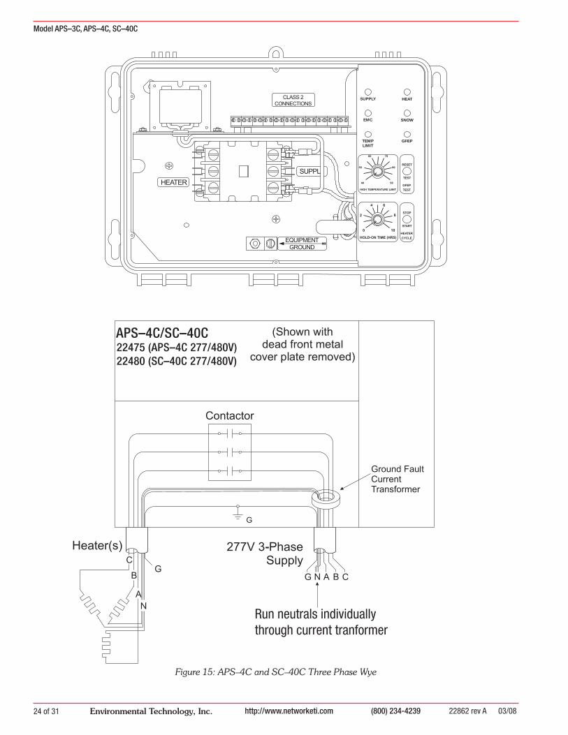
Figure 15: APS–4C and SC–40C Three Phase Wye
APS–4C/SC–40C22475 (APS–4C 277/480V)22480 (SC–40C 277/480V)
Run neutrals individuallythrough current tranformer
Model APS–3C, APS–4C, SC–40C
22862 rev A 03/08 (800) 234-4239 http://www.networketi.com 25 of 31Environmental Technology, Inc.
12345678910111213141516171819202122
S3
R3
R2
R1
D2
YEL
D1
GRN
R4
J1
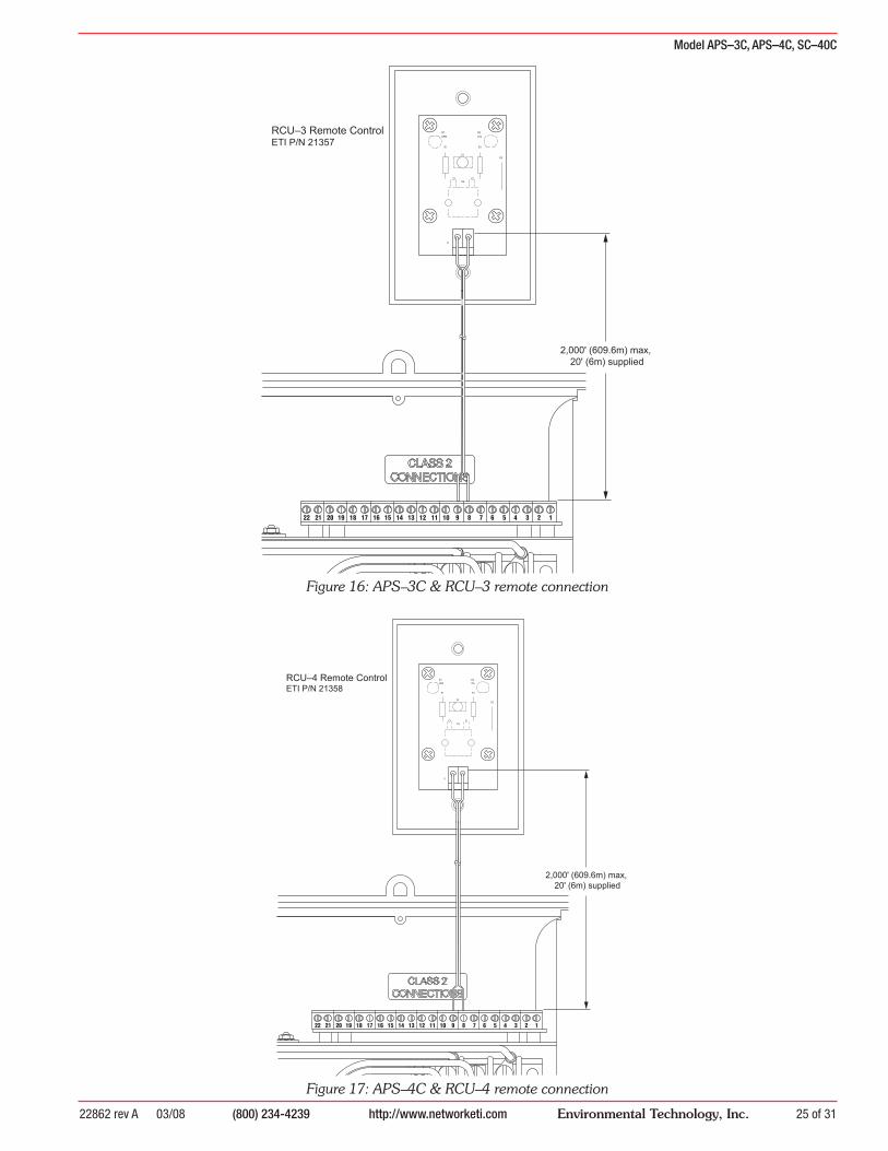
RCU–3 Remote ControlETI P/N 21357
2,000' (609.6m) max, 20' (6m) supplied
Figure 16: APS–3C & RCU–3 remote connection
Figure 17: APS–4C & RCU–4 remote connection
12345678910111213141516171819202122
S3
R3
R2
R1
D2
YEL
D1
GRN
R4
J1
RCU–4 Remote ControlETI P/N 21358
2,000' (609.6m) max, 20' (6m) supplied

Model APS–3C, APS–4C, SC–40C
22862 rev A 03/08(800) 234-4239http://www.networketi.com26 of 31 Environmental Technology, Inc.
HEATERSUPPL
CLASS 2CONNECTIONS
EQUIPMENTGROUND
0
2
4 6
8
10
HOLD-ON TIME (HRS)
SUPPL Y
EMC
TEMPLIMIT
HEA T
SNOW
GFEP
TEST
RESET
STAR T
STOP
HEA TER
CYCLE
GFEP
TESTHIGH TEMPERATURE LIMIT
40 90
50
60 70
80
SC–40C 240 VAC
HEATERSUPPL
CLASS 2CONNECTIONS
EQUIPMENTGROUND
0
2
4 6
8
10
HOLD-ON TIME (HRS)
SUPPL Y
EMC
TEMPLIMIT
HEA T
SNOW
GFEP
TEST
RESET
STAR T
STOP
HEA TER
CYCLE
GFEP
TESTHIGH TEMPERATURE LIMIT
40 90
50
60 70
80
APS–4C 240 VAC
Terminal 4Terminal 5
Terminal 6
Next SC–40C
4567 4567
Figure 18: APS–4C/SC–40C Communication Bus Connections
Figure 19: APS–3C/APS–4C Sensor Connections
12345678910111213141516171819202122
Red
White
BlackRed
White
Black
Red
White
Bla
ck
CIT–1Aerial Snow Sensor
SIT–6EPavement-Mounted Sensor
Red
Whi
te
Bla
ck
Model APS–3C, APS–4C, SC–40C
22862 rev A 03/08 (800) 234-4239 http://www.networketi.com 27 of 31Environmental Technology, Inc.
12345678910111213141516171819202122
Output CommonHeat
RelaySnow
RelayAlarm
RelaySupply
Relay
High Temperature Limit
RelayOverride On
Override Off
Input GND
Heat
Snow
Alarm
Supply
High Temperature Limit
Override On
Override Off
Figure 20: APS–3C/APS–4C/SC–40C EMC connections
EMC
Building Automation Energy Management Computer

Model APS–3C, APS–4C, SC–40C
22862 rev A 03/08(800) 234-4239http://www.networketi.com28 of 31 Environmental Technology, Inc.
12345678910111213141516171819202122
20 A A COM V/O
Figure 21: APS–3C/APS–4C/SC–40C Electrician’s DVM
Model APS–3C, APS–4C, SC–40C
22862 rev A 03/08 (800) 234-4239 http://www.networketi.com 29 of 31Environmental Technology, Inc.
12345678910111213141516171819202122
470K 5% 1/4 W.
Figure 23: APS–3C/APS–4C/SC–40C Resistor connections
12345678910111213141516171819202122
Figure 22: APS–3C/APS–4C/SC–40C Thermistor connections

Model APS–3C, APS–4C, SC–40C
22862 rev A 03/08(800) 234-4239http://www.networketi.com30 of 31 Environmental Technology, Inc.
Contactor ConnectionsContactor
Number
Connection
1 Sensor Connection (White wire)2 Sensor Connection (Black wire)3 Sensor Connection (Red wire)4 Satellite Panel Connection 5 Satellite Panel Connection 6 Satellite Panel Connection7 Satellite Panel Connection 8 RCU–3/RCU–4 Connection9 RCU–3/RCU–4 Connection10 Thermistor Connection11 Thermistor Connection12 Electrician’s DVM13 Electrician’s DVM14 Output Common15 Heat16 Snow17 Alarm18 Supply19 High Temperature Limit20 Override On21 Override Off22 Close Override On/Off Circuit
Model APS–3C, APS–4C, SC–40C
22862 rev A 03/08 (800) 234-4239 http://www.networketi.com 31 of 31Environmental Technology, Inc.
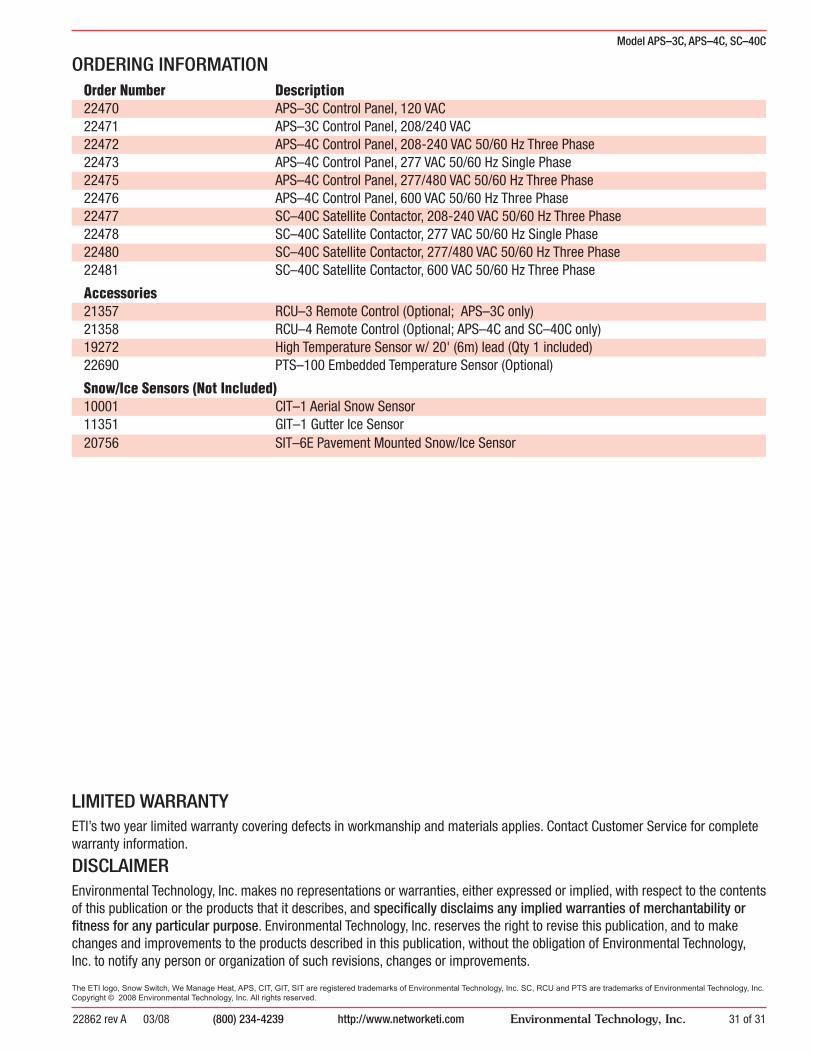
ORDERING INFORMATIONOrder Number Description
22470 APS–3C Control Panel, 120 VAC22471 APS–3C Control Panel, 208/240 VAC22472 APS–4C Control Panel, 208-240 VAC 50/60 Hz Three Phase22473 APS–4C Control Panel, 277 VAC 50/60 Hz Single Phase22475 APS–4C Control Panel, 277/480 VAC 50/60 Hz Three Phase22476 APS–4C Control Panel, 600 VAC 50/60 Hz Three Phase22477 SC–40C Satellite Contactor, 208-240 VAC 50/60 Hz Three Phase22478 SC–40C Satellite Contactor, 277 VAC 50/60 Hz Single Phase22480 SC–40C Satellite Contactor, 277/480 VAC 50/60 Hz Three Phase22481 SC–40C Satellite Contactor, 600 VAC 50/60 Hz Three Phase
Accessories
21357 RCU–3 Remote Control (Optional; APS–3C only)21358 RCU–4 Remote Control (Optional; APS–4C and SC–40C only)19272 High Temperature Sensor w/ 20' (6m) lead (Qty 1 included)22690 PTS–100 Embedded Temperature Sensor (Optional)
Snow/Ice Sensors (Not Included)
10001 CIT–1 Aerial Snow Sensor11351 GIT–1 Gutter Ice Sensor20756 SIT–6E Pavement Mounted Snow/Ice Sensor
LIMITED WARRANTYETI’s two year limited warranty covering defects in workmanship and materials applies. Contact Cus tom er Service for complete warranty information.
DISCLAIMEREnvironmental Technology, Inc. makes no representations or warranties, either expressed or implied, with respect to the contents of this publication or the products that it describes, and specifi cally disclaims any implied warranties of mer chant abil i ty or fi tness for any particular purpose. En vi ron men tal Technology, Inc. reserves the right to revise this pub li ca tion, and to make changes and im prove ments to the products described in this publication, with out the ob li ga tion of En vi ron men tal Tech nol o gy, Inc. to notify any person or or ga ni za tion of such revisions, chang es or improvements.
The ETI logo, Snow Switch, We Manage Heat, APS, CIT, GIT, SIT are reg is tered trademarks of En vi ron men tal Technology, Inc. SC, RCU and PTS are trademarks of Environmental Technology, Inc. Copyright © 2008 Environmental Technology, Inc. All rights reserved.


![IS 4239 (1970): Mechanical Bevel Protractors · 2013. 9. 10. · IS 4239 (1970): Mechanical Bevel Protractors [PGD 25: Engineering Metrology] Title: IS 4239 (1970): Mechanical Bevel](https://static.fdocuments.us/doc/165x107/6141c39fd64cc55ff07560ff/is-4239-1970-mechanical-bevel-protractors-2013-9-10-is-4239-1970-mechanical.jpg)