Installation and Operation Guide for PD52 & PD53 Series ...
4
110537D Installation and Operation Guide for PD52 & PD53 Series Automatic Transfer Switch LIMITED WARRANTY I. LIMITED WARRANTY: Progressive Dynamics, Inc. warrants its power control center to be free from defects in material or workmanship under normal use and service; and limits the remedies to repair or replacement. II. DURATION: This warranty shall extend for a period of two years from the original date of purchase, and is valid only within the continental limits of the United States and Canada. III. WARRANTY EXCLUSIONS: This warranty specifically does not apply to: A. Any product which has been repaired or altered in any way by an unauthorized person or service station; B. Damage caused by excessive input voltage, misuse, negligence or accident; or an external force; C. Any product which has been connected, installed or adjusted or used other than in accordance with the instructions furnished, or has had the serial number altered, defaced or removed; D. Cost of all services performed in removing and re-installing the power converter; and E. ANY LOST PROFITS, LOST SAVINGS, LOSS OF USE OF ENJOYMENT OR OTHER INCIDENTAL DAMAGES ARISING OUT OF THE USE OF, OR INABILITY TO USE, THE PRODUCT. THIS INCLUDES DAMAGES TO PROPERTY AND, TO THE EXTENT PERMITTED BY LAW, DAMAGES FOR PERSONAL INJURY. THIS WARRANTY IS IN LIEU OF ALL OTHER WARRANTIES, INCLUDING IMPLIED WARRANTIES OF MERCHANTABILITY AND FITNESS FOR A PARTICULAR PURPOSE. IV. PROOF OF PURCHASE: A warranty claim must be accompanied by proof of the date of purchase. V. CLAIM PROCEDURE: Upon discovery of any defect, Progressive Dynamics, Inc. shall be supplied the following information at the address listed in this manual: A. Name and address of the claimant; B. Name, model and serial number of the product; C. Application in which product was installed. (Includes manufacturer, model and model year where applicable) D. Date of purchase; and E. Complete description of the claimed defect. Upon determination that a warranty claim exists (a defect in material or workmanship occurring under normal use and service,) the product shall be shipped postage prepaid to Progressive Dynamics, Inc. together with proof of purchase. The product will be repaired or replaced and returned postage prepaid. Progressive Dynamics Inc. 507 Industrial Rd. Marshall, MI 49068 [email protected] www.progressivedyn.com
Transcript of Installation and Operation Guide for PD52 & PD53 Series ...

110537D
Installation and Operation Guide for PD52 & PD53 Series Automatic Transfer Switch
LIMITED WARRANTY
I. LIMITED WARRANTY: Progressive Dynamics, Inc. warrants its power control center to be free
from defects in material or workmanship under normal use and service; and limits the remedies to repair or replacement.
II. DURATION: This warranty shall extend for a period of two years from the original date of purchase,
and is valid only within the continental limits of the United States and Canada. III. WARRANTY EXCLUSIONS: This warranty specifically does not apply to:
A. Any product which has been repaired or altered in any way by an unauthorized person or service station;
B. Damage caused by excessive input voltage, misuse, negligence or accident; or an external force; C. Any product which has been connected, installed or adjusted or used other than in accordance with
the instructions furnished, or has had the serial number altered, defaced or removed; D. Cost of all services performed in removing and re-installing the power converter; and E. ANY LOST PROFITS, LOST SAVINGS, LOSS OF USE OF ENJOYMENT OR OTHER
INCIDENTAL DAMAGES ARISING OUT OF THE USE OF, OR INABILITY TO USE, THE PRODUCT. THIS INCLUDES DAMAGES TO PROPERTY AND, TO THE EXTENT PERMITTED BY LAW, DAMAGES FOR PERSONAL INJURY. THIS WARRANTY IS IN LIEU OF ALL OTHER WARRANTIES, INCLUDING IMPLIED WARRANTIES OF MERCHANTABILITY AND FITNESS FOR A PARTICULAR PURPOSE.
IV. PROOF OF PURCHASE: A warranty claim must be accompanied by proof of the date of purchase. V. CLAIM PROCEDURE: Upon discovery of any defect, Progressive Dynamics, Inc. shall be supplied
the following information at the address listed in this manual:
A. Name and address of the claimant; B. Name, model and serial number of the product; C. Application in which product was installed. (Includes manufacturer, model and model year where
applicable) D. Date of purchase; and E. Complete description of the claimed defect.
Upon determination that a warranty claim exists (a defect in material or workmanship occurring under normal use and service,) the product shall be shipped postage prepaid to Progressive Dynamics, Inc. together with proof of purchase. The product will be repaired or replaced and returned postage prepaid.
Progressive Dynamics Inc. 507 Industrial Rd.
Marshall, MI 49068 [email protected]
www.progressivedyn.com

Consult a licensed electrician or RV technician for installation assistance
INSTALLATION INSTRUCTIONS
WARNING: TORQUE ALL CONNECTIONS PER LABEL – EXCESSIVE TORQUE MAY CAUSE DAMAGE TO CONNECTIONS LEADING TO A FIRE CAUSING PROPERTY DAMAGE, SERIOUS INJURY OR
DEATH.
WARNING: SHOCK HAZARD - DUE TO THE HIGH VOLTAGES ASSOCIATED WITH ITS OPERATION ONLY QUALIFIED SERVICE PERSONNEL SHOULD INSTALL OR TROUBLESHOOT THIS TRANSFER
SWITCH! ALL APPLICABLE CODES AND STANDARDS MUST BE MET WHEN INSTALLING THIS DEVICE. SEE WIRING DIAGRAM INSIDE OF THE COVER AND ON THE BACK OF THIS PAGE.
IMPROPER HANDLING OR INSTALLATION MAY CAUSE SERIOUS INJURY OR DEATH.
WARNING: THE 5200 & 5300 SERIES AUTOMATIC TRANSFER SWITCHES ARE NOT IGNITION PROTECTED AND SHOULD NOT BE MOUNTED IN THE SAME COMPARTMENT AS BATTERIES OR FLAMMABLE MATERIALS SUCH AS GASOLINE. DO NOT MOUNT THE TRANSFER SWITCH IN THE
GENERATOR OR LP GAS COMPARTMENT. A FIRE CAUSING PROPERTY DAMAGE SERIOUS INJURY OR DEATH COULD RESULT!
THESE PRODUCTS ARE NOT DESIGNED FOR USE WITH 240 VOLT SINGLE LEG SUPPLIES.
APPLICATION OF VOLTAGES IN EXCESS OF 130 VOLTS FROM HOT TO NEUTRAL MAY CAUSE PERMANENT DAMAGE TO THE UNIT.
The 5200 & 5300 Automatic Transfer Switches can be installed as shown in figures 1 and 2 provided there is room to route the shore power, generator, and distribution connection wires. The 5200 & 5300 Automatic Transfer Switches including the Remote Display are not suitable for outdoor locations and should be mounted in a protected area. We recommend that the transfer switch be mounted as close to the shore power and generator power cords as practical to reduce voltage loss.
REFER TO WIRING DIAGRAMS LOCATED INSIDE THE COVER FOR ALL CONNECTION INFORMATION AND TORQUE REQUIREMENTS.
PROPER MOUNTING CONFIGURATIONS:
OPTIONAL VOLTAGE SENSE CONNECTION: (Used for Auto Generator Start)
For transfer switches supplied with the optional voltage sense PCB assembly, connect the ’16 VAC OUT’ connections to the ‘Shore Power Present’ inputs of your generator control center. These connections do not have a polarity requirement. This output will be 16VAC whenever shore power is present.
Figure 1 – Horizontal Wall Mount Figure 2 – Floor Mount
Consult a licensed electrician or RV technician for installation assistance
GENERAL OPERATION When power is applied to the shore side, the contactor activates and supplies power to the panel - GREEN shore LED on
front panel will light. When power is applied to the Gen side there is a 20-45 second delay then the Gen side contact will activate, power will go to
the panel from the Gen side and the shore side will be locked out - GREEN generator LED on front panel will light. If shore power returns while the Gen power is present, nothing will happen. When the Gen power is removed the contactor
will drop out and allow the shore side to supply power. In a single leg application, the HOT1 side must be used for the control circuitry to work. For models with surge protection,
both HOT1 and HOT2 must have power applied for proper operation.
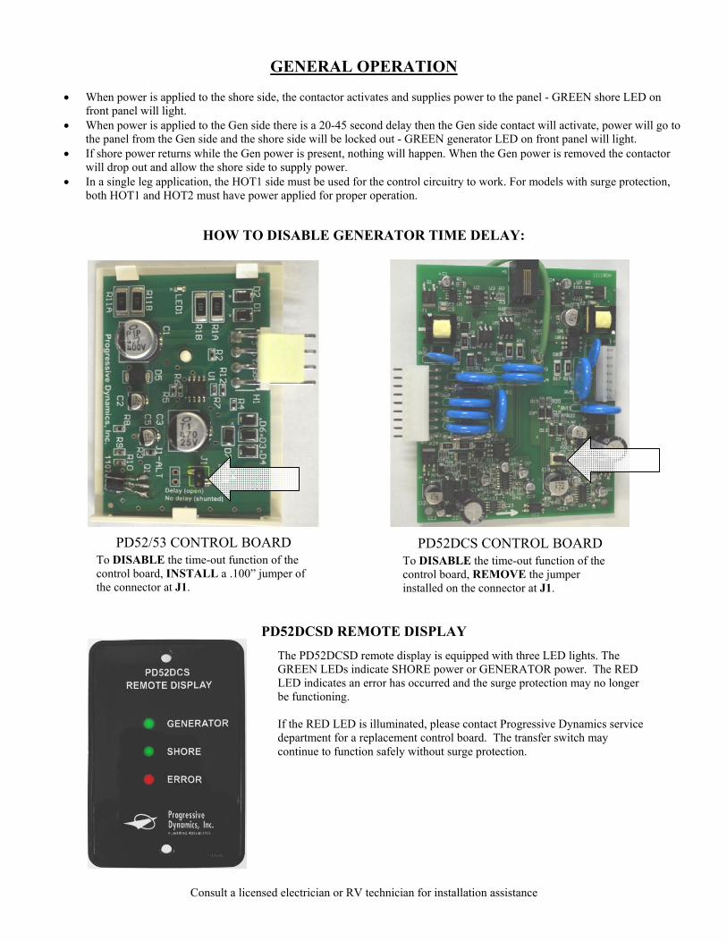
HOW TO DISABLE GENERATOR TIME DELAY:
PD52DCSD REMOTE DISPLAY
PD52/53 CONTROL BOARD To DISABLE the time-out function of the control board, INSTALL a .100” jumper of the connector at J1.
PD52DCS CONTROL BOARD To DISABLE the time-out function of the control board, REMOVE the jumper installed on the connector at J1.
The PD52DCSD remote display is equipped with three LED lights. The GREEN LEDs indicate SHORE power or GENERATOR power. The RED LED indicates an error has occurred and the surge protection may no longer be functioning. If the RED LED is illuminated, please contact Progressive Dynamics service department for a replacement control board. The transfer switch may continue to function safely without surge protection.

Consult a licensed electrician or RV technician for installation assistance
Specifications
(Specifications subject to change without notice)
Model PD52_ PD52DCS_ PD53 Voltage Rating Current Rating (line) Current Rating (neutral) Dominant Source Open Neutral Protection Reverse Polarity Protection Safety Interlocks Under Voltage Protection Over Voltage Protection Multimode Surge Protection
Surge Energy Rating Surge Current Rating
Weight Dimensions Listed
120/240Vac 50A 70A
Generator No No
Mechanical & Electrical No No No n/a n/a
7 lbs 10.38L x 6.88W x 4.50H
Yes
120/240Vac 50A 70A
Generator Yes Yes
Mechanical & Electrical Yes Yes Yes
3,300 Joules 103,000A
10 lbs 10.25L x 8.25W x 5.50H
Yes
120/240Vac 100A 100A
Generator No No
Mechanical & Electrical No No No n/a n/a
17 lbs 12.00L x 10.00W x 6.00H
No
TROUBLESHOOTING GUIDE
PROBLEM POSSIBLE CAUSES ACTION
No Output when Plugged into Shore Power
Wiring error between shore power and the transfer switch.
Correct wiring
Defective transfer switch Replace transfer switch
Wiring error between generator and the transfer switch
Correct wiring
Generator malfunction Have generator serviced
No Output when Generator is Running
Wiring error between generator and the transfer switch.
Correct wiring
Generator malfunction Have generator serviced
Defective transfer switch Replace transfer switch
No Output to Auto Generator Start
Wiring error between shore power and the transfer switch.
Correct wiring
Bad voltage sense control board. Replace control board
Red LED(s) Illuminated (surge protected models only)
Surge protection has been damaged and is no longer functional.
Replace control board assembly. (Contact Progressive Dynamics service department for correct control board assembly)
See website www.progressivedyn.com for more troubleshooting information and return instructions
NOTES: