Installation and Operating ManualJupiter Avionics Corporation 1959 Kirschner Road Kelowna BC Canada...
16
Rev B Page i UJAC-001 Panel Mount USB Charger Installation and Operating Manual Rev A Jupiter Avionics Corporation 1959 Kirschner Road Kelowna BC Canada V1Y 4N7 Tel: +1 778 478 2232 Toll-Free: 1 855 478 2232 www.jupiteravionics.com
Transcript of Installation and Operating ManualJupiter Avionics Corporation 1959 Kirschner Road Kelowna BC Canada...

Rev B Page i
UJAC-001
Panel Mount USB Charger
Installation and Operating Manual Rev A
Jupiter Avionics Corporation 1959 Kirschner Road
Kelowna BC Canada V1Y 4N7
Tel: +1 778 478 2232 Toll-Free: 1 855 478 2232 www.jupiteravionics.com

UJAC-001 Panel Mount USB Charger Installation and Operating Manual
Rev A Page ii
Copyright 2017 Jupiter Avionics Corp.
All rights reserved
Jupiter Avionics Corporation (JAC) permits a single copy of this manual to be printed or downloaded for the express use of an installing agency. Any such electronic or printed copy of this manual must contain the complete text of this copyright notice. Any unauthorized commercial distribution of this manual is strictly prohibited. Except as described above, no part of this manual may be reproduced, copied, transmitted, disseminated, downloaded, or stored in any storage medium for any purpose without the express prior written consent of JAC.
RECORD OF REVISIONS Revision Rev Date Description ECR
A Jun 2017 Initial release, Serial number 1001 and higher. 4743
Prepared:
MPB
Checked: Approved:
IMPORTANT:
Information in this document is subject to change without notice.
To confirm the current revision status of this manual, visit the JAC website:
www.jupiteravionics.com
JAC
CPM07-05-17
JAC
KDV07-05-17

UJAC-001 Panel Mount USB Charger Installation and Operating Manual
Rev A Page iii
Table of Contents SECTION 1 - DESCRIPTION ................................................................................................................................................. 1
1.1 System Overview .................................................................................................................................................... 1 1.2 Features Overview .................................................................................................................................................. 1 1.3 Inputs and Outputs .................................................................................................................................................. 1
1.3.1 Inputs ............................................................................................................................................................... 1 1.3.2 Outputs ............................................................................................................................................................ 1 1.3.3 Bi-directional .................................................................................................................................................... 1
1.4 Specifications .......................................................................................................................................................... 1 1.4.1 Electrical Specifications................................................................................................................................... 1 1.4.2 Mechanical Specifications ............................................................................................................................... 2
SECTION 2 – INSTALLATION ............................................................................................................................................... 3 2.1 Introduction .............................................................................................................................................................. 3 2.2 Continued Airworthiness ......................................................................................................................................... 3 2.3 Unpacking and Inspecting Equipment..................................................................................................................... 3
2.3.1 Warranty .............................................................................................................................................................. 3 2.4 Installation Procedures ............................................................................................................................................ 3
2.4.1 Installation Limitations ......................................................................................................................................... 3 2.4.2 Cabling and Wiring .............................................................................................................................................. 3 2.4.3 Mechanical Installation ........................................................................................................................................ 4 2.4.4 Post Installation Checks ...................................................................................................................................... 4
2.5 Installation Kit .......................................................................................................................................................... 4 2.5.1 Recommended Crimp Tools ........................................................................................................................... 4
2.6 Installation Drawings ............................................................................................................................................... 4 SECTION 3 – OPERATION .................................................................................................................................................... 5
3.1 Introduction .............................................................................................................................................................. 5 3.2 Front Panel Connector ............................................................................................................................................ 5
3.2.1 USB Power Output + 5Vdc / 2.1A .................................................................................................................... 5 3.3 Compatibility ............................................................................................................................................................ 5
Appendix A - Installation Drawings ................................................................................................................................... A1 A1 Introduction ............................................................................................................................................................ A1 A2 Installation Drawings ............................................................................................................................................. A1
Appendix B - Installation Documents ............................................................................................................................... B1 B1 Airworthiness Approval ......................................................................................................................................... B2 B2 Instructions for Continued Airworthiness .............................................................................................................. B2

Rev A Page 1
UJAC-001 Panel Mount USB Charger
SECTION 1 - DESCRIPTION
1.1 System Overview
The UJAC-001 Panel Mount USB Charger allows the aircraft power to charge USB devices.
1.2 Features Overview
The UJAC-001 faceplate has a baked-on flat black urethane finish to resist scratches and nicks during use.
The UJAC-001 provides a single USB 2.0 Type A receptacle with 5 Vdc and up to 2.1 Amps of current.
The UJAC-001 provides a flexible urethane cover to protect the USB port when not in use.
1.3 Inputs and Outputs
Refer to the UJAC-001 connector map for the mating connector designators and pin assignments for the input and output signals.
1.3.1 Inputs
Name Qty Type POWER INPUT 1 Power supply
1.3.2 Outputs
Name Qty Type +5VDC 1 Power supply
1.3.3 Bi-directional
Name Qty Type D+ and D- 2 Data Lines
1.4 Specifications
1.4.1 Electrical Specifications
Power Input
28 Vdc 32.2 Vdc 20.5 Vdc
≤ 0.75 A
Primary nominal voltage Maximum voltage Minimum voltage
Input current at 28 Vdc
USB Power Output
2.10 A ±10%Output rated current Output rated voltage +5 Vdc ±12%

UJAC-001 Panel Mount USB Charger Installation and Operating Manual
Rev A Page 2
1.4.2 Mechanical Specifications
Faceplate diameter
Faceplate thickness
Diameter behind panel
1.86 in [47.2 mm] max
0.22 in [5.6 mm] max
1.76 in [44.7 mm] max
Depth behind (not including connectors)
J1 J2
Weight
Material
Faceplate and Chassis finish
Connectors (2):
Mounting
Bonding
Installation Kit part number
0.90 in [22.9 mm] max 0.21 lb [0.10 kg] max 6061-T651 aluminum Flat Black Urethane Paint One 9-pin D-Sub male locking One USB Type A Female Two 4-40 Countersunk screws ≤ 2.5 mΩ INST-UJAC

Rev A Page 3
UJAC-001 Panel Mount USB Charger
SECTION 2 – INSTALLATION
2.1 Introduction
This section contains unpacking and inspection procedures, installation information, and post-installation checks.
2.2 Continued Airworthiness
Maintenance of the UJAC-001 is on condition only. Scheduled inspection and/or periodic maintenance of this unit is not required.
2.3 Unpacking and Inspecting Equipment
Unpack the equipment carefully. Check for shipping damage and report any problems to the relevant carrier. Confirm that the Authorized Release Certificate or Certificate of Conformance is included. Complete the on-line warranty card from the Jupiter Avionics Corporation (JAC) website - www.jupiteravionics.com/warranty
2.3.1 Warranty
This product manufactured by JAC is warranted to be free of defects in workmanship or performance for 2 years from the date of installation by an approved JAC dealer or agency. This warranty covers the cost of all materials and labour to repair or replace the unit, but does not include the cost of transporting the defective unit to and from JAC or its designated warranty repair centre, or of removing and replacing the defective unit in the aircraft. This warranty does not cover failures due to abuse, misuse, accident, or unauthorized alteration or repairs.
THIS WARRANTY IS VOID IF THE PRODUCT IS NOT INSTALLED BY AN AUTHORIZED JAC DEALER. If the on-line warranty card is not completed, the product will be warranted from the date of manufacture.
Contact JAC for return authorization, and for any questions regarding this warranty and how it applies to your unit(s). JAC is the final arbiter concerning warranty issues.
2.4 Installation Procedures
CAUTION: The power input circuitry of the unit may be damaged if the installation does not conform to the wiring instructions in this manual.
2.4.1 Installation Limitations
Those installing the UJAC-001, on or in a specific type or class of aircraft, must determine that the aircraft installation conditions meet standards. The UJAC-001 may be installed only by following the applicable airworthiness requirements.
2.4.2 Cabling and Wiring
All wire shall be selected in accordance with the original aircraft manufacturer’s maintenance instructions, or AC43.13-1B Change 1, Paragraphs 11-76 through 11-78. Unshielded wire types shall qualify to MIL-W-22759 as specified in AC43.13-1B Change 1, Paragraphs 11-85, 11-86, and listed in Table 11-11. Follow the Connector Map in Appendix A of this manual.

UJAC-001 Panel Mount USB Charger Installation and Operating Manual
Rev A Page 4
Maintain wire segregation and route wiring in accordance with the original aircraft manufacturer’s maintenance instructions.
Unless otherwise noted, all wiring shall be a minimum of 22 AWG. Refer to the Interconnect drawing for additional specifications. Check that the ground connection is clean and well secured, and that it shares no path with any electrically noisy aircraft accessories such as blowers, turn-and-bank instruments, or similar loads.
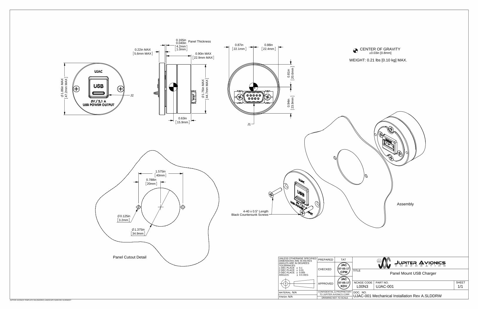
2.4.3 Mechanical Installation
The UJAC-001 can be mounted in any attitude and location with adequate space for the front panel and sufficient clearance for the connector and wiring harness. It requires no direct cooling.
2.4.4 Post Installation Checks
2.4.4.1 Voltage/Resistance checks.
Do not attach this unit until the following conditions are met:
a) Check P1 pin 1 for +27.5 Vdcb) Check P1 pins 6 and 7 for continuity to ground (less than 0.5 Ω).c) Check all pins for shorts to ground or adjacent pins.
2.4.4.2 Power on Checks.
Power up the aircraft’s systems and confirm normal operation of all functions of the UJAC-001. Refer to Section 3 (Operation) for specific operational details.
When all performance checks are satisfied, complete the necessary regulatory documentation before releasing the aircraft for service. Refer to Appendix B.
2.5 Installation Kit
The kit required to install this unit is not included with the unit.
The installation kit (Part # INST-UJAC-001) consists of the following:
Quantity Description JAC Part # 1 D-Sub 9-pin connector, hood and 9 crimp pins CON-3400-0009
2.5.1 Recommended Crimp Tools
Standard D-Sub Crimp Tool Chart Tool Type Hand crimping tool Positioner Insertion/extractor tool
POSITRONIC 9507-0-0-0 9502-5-0-0 4711-2-0-0 DANIELS AFM 8 K13-1 91067-2 MIL-SPEC M22520/2-01 M22520/2-08 M81969/1-02
2.6 Installation Drawings
The drawings and documents required for Installation can be found in Appendix A of this manual.

Rev A Page 5
UJAC-001 Panel Mount USB Charger
SECTION 3 – OPERATION
3.1 Introduction
This section contains the operating instructions for the UJAC-001.
3.2 Front Panel Connector
The UJAC-001 has one front panel USB Power output connector.
3.2.1 USB Power Output + 5Vdc / 2.1A
This connector is provided to supply 5 Vdc up to 2.1 Amps, for charging cell phones and similar devices.
Note: This port is not designed to be used for data transfer
3.3 Compatibility
CAUTION:. Attempting to connect an incompatible plug or device could damage the UJAC-001, the attached device, or both. If in doubt, check with your installing agency.
Rev A Page A1
UJAC-001 Panel Mount USB Charger
Installation and Operating Manual
Appendix A - Installation Drawings
A1 Introduction
The drawings necessary for installation and troubleshooting of the UJAC-001 are in this Appendix, as listed below.
A2 Installation Drawings
DOCUMENT Rev
UJAC-001 Connector Map A
UJAC-001 Interconnect A
UJAC-001 Mechanical Installation A

JUPITER AVIONICS TEMPLATE AUTOCAD PORTRAIT SIZEA REV B.DWT
TITLE
APPROVED
PREPARED
CHECKED
L00N3
NCAGE CODE PART NO. SHEET
DOC NO.
1 2 3 4 5
6 7 8 9
9 PIN FEMALE DMIN
MATING CONNECTOR
VIEW IS FROM REAR OF MATING CONNECTOR
1/1
UJAC-001 Connector Map Rev A.pdf
UJAC-001
SP
AR
E 6
SP
AR
E 5
KV
CH
AS
SIS
GR
OU
ND
PO
WE
R G
RO
UN
D
SP
AR
E 4
SP
AR
E 3
PANEL MOUNT USB CHARGER
SP
AR
E 2
P1 - Main Connector
SP
AR
E 1
J1 PO
WE
R IN
PU
T
JAC
CPM07-05-17
JAC
KDV07-05-17

JUPITER AVIONICS TEMPLATE AUTOCAD PORTRAIT SIZEA REV B.DWT
TITLE
APPROVED
PREPARED
CHECKED
L00N3
NCAGE CODE PART NO. SHEET
DOC NO.
CONFIDENTIAL & PROPRIETARY
TO JUPITER AVIONICS CORP.
Panel Mount USB Charger
UJAC-001 1/2
UJAC-001 Interconnect Rev A.dwg
TAT
UJAC-001 INTERCONNECT WIRING NOTES
NOTES
ALL WIRE SIZE SHOULD BE 22 AWG MIN UNLESS OTHERWISE SPECIFIED. UNSHIELDED
WIRE SHOULD BE SELECTED PER FAA AC43.13-1B CHANGE 1 PARA 11-76 TO 11-78. WIRE
TYPES SHOULD BE IN ACCORDANCE WITH MIL-W-22759 AS DESCRIBED IN FAA AC43.13-1B
CHANGE 1 PARA 11-85 AND 11-86 AND LISTED IN TABLE 11-11 OR 11-12. ALL SHIELDED
CABLE SHOULD BE IN ACCORDANCE WITH MIL-DTL-27500 (REVISION H OR LATER).
CONNECTION TO AIRFRAME GROUND SHOULD BE MADE WITH 22 AWG WIRE. LENGTH NOT
TO EXCEED 3 FT (0.91 M).
CABLE LENGTH NOT TO EXCEED 6 FT (1.82 M).
2
1.
3
JAC
CPM07-05-17
JAC
KDV07-05-17

POWER INPUT 1
SPARE 5
SPARE 6
8
9
CHASSIS GROUND 7
UJAC-001 MAIN
P1
9 PIN FEMALE DMIN
MATING CONNECTOR
CHASSIS GROUND
22 AWG
2
JUPITER AVIONICS TEMPLATE AUTOCAD PORTRAIT SIZEA REV B.DWT
TITLE
APPROVED
PREPARED
CHECKED
L00N3
NCAGE CODE PART NO. SHEET
DOC NO.
CONFIDENTIAL & PROPRIETARY
TO JUPITER AVIONICS CORP.
Panel Mount USB Charger
UJAC-001 2/2
UJAC-001 Interconnect Rev A.dwg
TAT
+ 28 VDC POWER
1A
POWER GROUND 6
+5V 1
P2
USB TYPE A MALE
MATING CONNECTOR
D- 2
D+ 3
GROUND 4
VBUS1
D-2
D+3
GROUND4
22 AWG
22 AWG
UJAC-001 USB
J2
J1
CHARGEABLE USB DEVICE
2
3
SPARE 4 5
SPARE 3 4
SPARE 2 3
SPARE 1 2
JAC
CPM07-05-17
JAC
KDV07-05-17
CENTER OF GRAVITY
WEIGHT: 0.21 lbs [0.10 kg] MAX.
0.03in [0.8mm]
0.63in15.9mm
0.88in22.4mm
23
.9m
m0.
94in
20.6
mm
0.81
in
0.87in22.1mm
4-40 x 0.5" LengthBlack Countersunk Screws
Panel Cutout Detail
Assembly
20mm
3.2mm0.125in
1.575in40mm
0.788in
1.375in34.9mm
CONFIDENTIAL & PROPRIETARY
0.5 DEG
JUPITER AVIONICS TEMPLATE SOLIDWORKS LANDSCAPE SIZEB REV B.DRWDOT
UJAC-001 Mechanical Installation Rev A.SLDDRWDOC. NO.
1/1SHEET
UJAC-001PART NO.
TITLE
DRAWING NOT TO SCALETO JUPITER AVIONICS CORP.
APPROVED
CHECKED
TATPREPARED
N/AN/AMATERIAL:
FINISH:
NCAGE CODEL00N3
UNLESS OTHERWISE SPECIFIEDDIMENSIONS ARE IN INCHESANGLES ARE IN DEGREESTOLERANCES:1 DEC PLACE: 0.12 DEC PLACE: 0.013 DEC PLACE: 0.005ANGLES: Panel Mount USB Charger
J21.86
in M
AX47
.2m
m M
AX
0.22in MAX5.6mm MAX
0.90in MAX
22.9mm MAX
0.040in4.2mm1.0mm
Panel Thickness0.165in
1.76
in M
AX44
.7m
m M
AX
J1
JAC
CPM07-05-17
JAC
KDV07-05-17

Rev A Page B1
UJAC-001 Panel Mount USB Charger
Installation and Operating Manual
Appendix B - Installation Documents

UJAC-001 Panel Mount USB Charger Installation and Operating Manual
Rev A Page B2
B1 Airworthiness Approval
Airworthiness approval of the UJAC-001 may require completion of a TCCA Major Modification Report per CAR STD (AWM) 571 Appendix L, or a FAA Form 337. The sample wording for a description of the work is provided to assist the Installing Agency in preparing Instructions for Continued Airworthiness (ICA) when replacing an existing audio panel with a Jupiter Avionics UJAC-001 Panel Mount USB Charger. This sample may be modified appropriately for new installations. It is the installer’s responsibility to determine the applicability of the method used. Installations performed outside Canada must follow the applicable aviation authority’s regulations.
Sample Wording: Removed the existing [model] audio panel and replaced with a Jupiter Avionics UJAC-001 Panel Mount USB Charger in [aircraft location].
See Section 1 of the UJAC-001 Installation Manual.
Installed in accordance with the UJAC-001 Installation Manual, Revision [ ], and AC 43.13-2, Chapters 2, and 3.
The UJAC-001 interfaces with existing aircraft systems per the Installation & Operating Manual instructions.
The UJAC-001 Installation& Operating Manual provides detailed installation instructions and wiring diagrams (Section 2, and Appendices A and B).
Power is supplied to the UJAC-001 through a [ ]-Amp circuit breaker.
Aircraft equipment list, weights and balance amended. Compass compensation checked and found to conform to applicable regulations.
B2 Instructions for Continued Airworthiness Maintenance of the UJAC-001 Panel Mount USB Charger is “on condition” only. Refer to the UJAC-001 Maintenance Manual. Periodic maintenance of the UJAC-001 is not required.
The following sample Instructions for Continued Airworthiness (ICA) provides assistance in preparing ICA for the Jupiter Avionics UJAC-001 unit installation as part of a Type Certificate (TC) or Supplemental Type Certificate (STC) project to comply with CAR STD (AWM) 523/527/525/529.1529 or FAR 23/25/27/29.1529 “Instructions for Continued Airworthiness”.
Items that may vary by aircraft make and model are shown in brackets (“[ ]”) and should be filled in as appropriate. Some of the checklist items do not apply, in which case they should be marked “N/A” (Not Applicable).
Instructions for Continued Airworthiness, Jupiter Avionics UJAC-001 Panel Mount USB Charger in an [Aircraft Make and Model] 1. Introduction
[Aircraft that has been altered: Registration number, Make, Model and Serial Number]
Content, Scope, Purpose and Arrangement: This document identifies the Instructions for Continued Airworthiness for a Jupiter Avionics UJAC-001 installed in an [aircraft make and model].
Applicability: Applies to a Jupiter Avionics UJAC-001 installed in an [aircraft make and model].
Definitions/Abbreviations: None, N/A.
Precautions: None, N/A.
Units of Measurement: None, N/A.
Referenced Publications: UJAC-001 Installation and Operating Manual UJAC-001 Maintenance Manual STC/TC # [applicable STC/TC number for the specific aircraft installation]
Distribution: This document should be a permanent aircraft record.

UJAC-001 Panel Mount USB Charger Installation and Operating Manual
Rev A Page B3
2. Description of the System/Alteration Jupiter Avionics UJAC-001 Panel Mount USB Charger with interface to external transceivers and [include other equipment/systems as appropriate]. Refer to Appendix A of this manual for interconnect information. Refer to aircraft manufacturer approved interconnect for actual installation.
3. Control, Operation Information Refer to section 3 of this manual or to the Jupiter Avionics UJAC-001 Operating Manual. (N/A if no controls.)
4. Servicing Information N/A
5. Maintenance Instructions Maintenance of the UJAC-001 is ‘on condition’ only. Periodic maintenance is not required. Refer to the UJAC-001 Maintenance Manual.
6. Troubleshooting Information Refer to the UJAC-001 Maintenance Manual.
7. Removal and Replacement Information Refer to Section 2 of this manual - the UJAC-001 Installation and Operating Manual. If the unit is removed and reinstalled, a functional check of the equipment should be conducted.
8. Diagrams Refer to Appendix A of this manual - the UJAC-001 Installation and Operating Manual - for installation drawings and interconnect examples.
9. Special Inspection Requirements N/A
10. Application of Protective Treatments N/A
11. Data: Relative to Structural Fasteners UJAC-001 and appropriate mounting hardware installation, removal and replacement should be in accordance with applicable provisions of AC 43.13-1B and AC 43.13-2A.
12. Special Tools N/A
13. This Section is for Commuter Category Aircraft Only A. Electrical loads: Refer to Section 1 of the UJAC-001 Installation and Operating Manual. B. Methods of balancing flight controls: N/A. C. Identification of primary and secondary structures: N/A. D. Special repair methods applicable to the airplane: N/A.
14. Overhaul Period No additional overhaul time limitations.
15. Airworthiness Limitation Section N/A