Installation and operating instructions -...
36
LCD 108 Installation and operating instructions GRUNDFOS INSTRUCTIONS
-
Upload
truonghuong -
Category
Documents
-
view
214 -
download
1
Transcript of Installation and operating instructions -...

LCD 108Installation and operating instructions
GRUNDFOS INSTRUCTIONS

En
glis
h (G
B)
English (GB) Installation and operating instructions
Original installation and operating instructions
CONTENTSPage
1. Symbols used in this document
2. GeneralThe LCD 108 controller is designed for the control of pumps in wastewater systems.
Type key:
1. Symbols used in this document 2
2. General 22.1 Applications 32.2 Variants 3
3. Location and mounting 33.1 Location 33.2 Mounting of LCD 108 for direct-on-line starting 33.3 Mounting of LCD 108 for star-delta starting 4
4. Systems for parallel operation with 3 float switches 54.1 Electrical connection 54.2 Setting 64.3 Control panel 84.4 Battery back-up functions 84.5 Reset button and ON-OFF-AUTO selector switch 9
5. Systems for parallel operation with 4 float switches 105.1 Electrical connection 105.2 Setting 105.3 Control panel 125.4 Battery back-up functions 125.5 Reset button and ON-OFF-AUTO selector switch 13
6. Systems for 100 % standby operation 146.1 Electrical connection 146.2 Setting 146.3 Control panel 166.4 Battery back-up functions 166.5 Reset button and ON-OFF-AUTO selector switch 17
7. System for full-control operation 187.1 Electrical connection 187.2 Setting 187.3 Control panel 207.4 Battery back-up functions 207.5 Reset button and ON-OFF-AUTO selector switch 21
8. Start-up 22
9. Maintenance 22
10. Technical data 23
11. Fault finding chart 24
12. Disposal 24
Warning
Prior to installation, read these installation and operating instructions. Installation and operation must comply with local regulations and accepted codes of good practice.
Warning
If these safety instructions are not observed, it may result in personal injury.
Warning
If these instructions are not observed, it may lead to electric shock with consequent risk of serious personal injury or death.
Warning
These instructions must be observed for explosion-proof pumps.
Caution If these safety instructions are not observed, it may result in malfunction or damage to the equipment.
NoteNotes or instructions that make the job easier and ensure safe operation.
Example LCD 108 400 3 23 SD
LCD = two-pump controller
108 = type designation
Phase voltage [V]
1 = single-phase3 = three-phase
Maximum operating current per pump [A]
SD = Star-delta starting
2
En
gli
sh
(G
B)
2.1 Applications
The LCD 108 enables:
• control of two pumps based on signals from float switches,
• automatic pump changeover (even distribution of operating hours on both pumps),
• selection of automatic test run during long periods of inactivity (every 24 hours),
• battery back-up in case of mains supply failure (accessory for certain variants),
• starting delay within the range from 0 to 255 sec. (random) after returning from battery operation to mains operation (resulting in an even mains load when several pumping stations are started up at the same time),
• selection of automatic alarm resetting,
• selection of automatic restarting,
• setting of stop delays matching the actual operating conditions,
• indication of liquid level,
• alarm indication of:
– inadmissibly high liquid level,
– overload (via motor protection relay),
– overtemperature (via PTC resistance or thermal switch in motor),
– wrong phase sequence (only certain variants),
– mains supply failure (only certain variants),
– defective float switch.
As standard, the LCD 108 has one alarm output for common alarm. Certain variants have an additional alarm output for separate high-level alarm.
Furthermore, the controller incorporates a buzzer (only certain variants).
2.2 Variants
The actual controller type, voltage variant, etc. are stated in the type key on the nameplate situated on the side of the controller cabinet.
The LCD 108 is available for either direct-on-line starting or star-delta starting.
The LCD 108 can be connected and set to operation/control in 4 different ways, see sections 4. to 7.:
• Section 4. Systems for parallel operation with 3 float switches.(Electrodes can also be used.)
• Section 5. Systems for parallel operation with 4 float switches.(Electrodes can also be used.)
• Section 6. Systems for 100 % standby operation.
• Section 7. System for full-control operation.
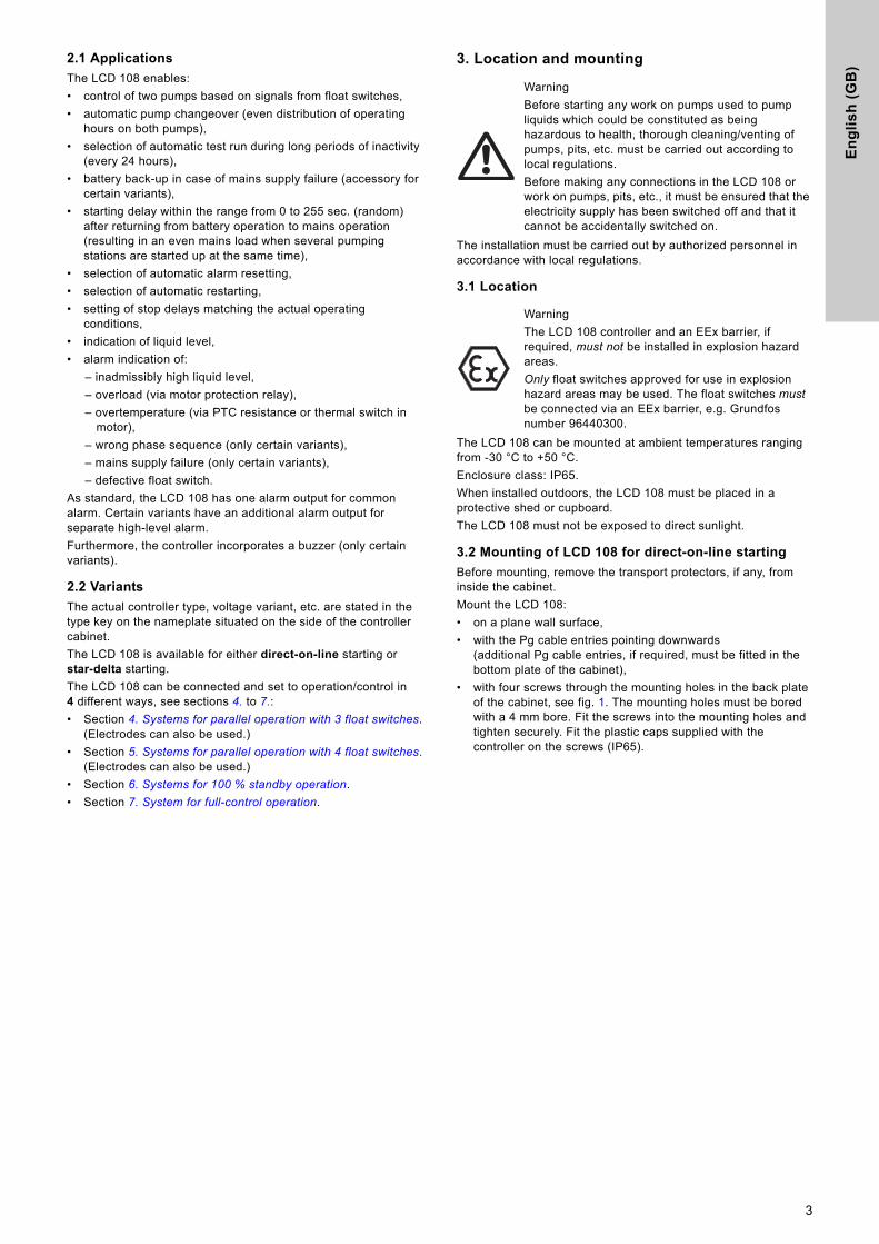
3. Location and mounting
The installation must be carried out by authorized personnel in accordance with local regulations.
3.1 Location
The LCD 108 can be mounted at ambient temperatures ranging from -30 °C to +50 °C.
Enclosure class: IP65.
When installed outdoors, the LCD 108 must be placed in a protective shed or cupboard.
The LCD 108 must not be exposed to direct sunlight.
3.2 Mounting of LCD 108 for direct-on-line starting
Before mounting, remove the transport protectors, if any, from inside the cabinet.
Mount the LCD 108:
• on a plane wall surface,
• with the Pg cable entries pointing downwards(additional Pg cable entries, if required, must be fitted in the bottom plate of the cabinet),
• with four screws through the mounting holes in the back plate of the cabinet, see fig. 1. The mounting holes must be bored with a 4 mm bore. Fit the screws into the mounting holes and tighten securely. Fit the plastic caps supplied with the controller on the screws (IP65).
Warning
Before starting any work on pumps used to pump liquids which could be constituted as being hazardous to health, thorough cleaning/venting of pumps, pits, etc. must be carried out according to local regulations.
Before making any connections in the LCD 108 or work on pumps, pits, etc., it must be ensured that the electricity supply has been switched off and that it cannot be accidentally switched on.
Warning
The LCD 108 controller and an EEx barrier, if required, must not be installed in explosion hazard areas.
Only float switches approved for use in explosion hazard areas may be used. The float switches must be connected via an EEx barrier, e.g. Grundfos number 96440300.
3

En
glis
h (G
B)
Figure 1 shows the internal construction of the LCD 108 for direct-on-line starting.
Fig. 1
Figure 2 shows the terminals listed under positions 2 and 3.
Fig. 2
Key to the symbols in figures 1 and 2:
3.3 Mounting of LCD 108 for star-delta starting
Before mounting, remove the transport protectors, if any, from inside the cabinet.
Mount the LCD 108:
• on a plane wall surface,
• with the Pg cable entries pointing downwards(additional Pg cable entries, if required, must be fitted in the bottom plate of the cabinet),
• with four screws through the mounting holes in the back plate of the cabinet or through the brackets supplied with the controller, fig. 4. The mounting holes must be bored with a 4 mm bore. Fit the screws into the mounting holes and tighten securely. Fit the plastic caps supplied with the controller on the screws (IP65).
Figure 3 shows the internal construction of the LCD 108 for star-delta starting.
Fig. 3
TM
01
43
83
02
99
TM
01
48
33
23
08
Pos. Description
1 Module CU 212.
2Terminal block for level inputs (11-12, 21-22, 31-32, 41-42).
3
Terminal block with:• input for the PTC resistance/thermal switch of the
motor (T11-T21, T12-T22),• output for external alarm device for high-level alarm
(H-NC, H-COM, H-NO) (only certain variants),• output for external alarm device for common alarm
(G-NC, G-COM, G-NO).
4Motor protection relays, pumps 1 and 2 (contacts and thermal relay fitted).
5 Terminal block for electricity supply.
6Fuse holders for control circuit fuses (1 to 3 depending on voltage/current variant).
7 Isolating transformer.
9 Pg cable entries.
10 Earth bar ( PE).
2212T21
T11
T22
T12
H-N
OH
-CO
MH
-NC
G-N
OG
-CO
MG
-NC
2111
32 42
31 41
Note
If the distance between the controller and pit exceeds 20 metres, it is not advisable to use electrodes as problems with the signal values sent back to the controller may arise.
In such cases, it is recommended to use float switches.
NoteCables of up to 100 metres can be connected between the controller and the float switches.
TM
01
81
25
50
99
4

En
gli
sh
(G
B)
Fig. 4
Figure 5 shows the terminals listed under positions 2 and 3.
Fig. 5
Key to the symbols in figures 3 and 5:
4. Systems for parallel operation with 3 float switches
Description (see also page 25 or 26):
The pumps are controlled by the liquid level in the pit.
• When the float switch, pos. 1, registers liquid, the first pump is started.
• When the float switch, pos. 2, registers liquid, the next pump is started.
• When the float switch, pos. 1, does not register any liquid, the "stop delay" is initiated (can be set). After expiration of the stop delay, both pumps are stopped.
• The pumps operate alternately.
The top float switch, pos. 3, activates the high-level alarm.
4.1 Electrical connection
Parallel operation with 3 float switches, pages 25 or 26.
Fig. 1 on page 25.
The figures show all electrical connections required to connect the LCD 108 for direct-on-line starting, parallel operation with 3 float switches.
Fig. 2 on page 26.
The figure shows all electrical connections required to connect the LCD 108 for star-delta starting, parallel operation with 3 float switches.
The operating voltage and frequency are marked on the controller nameplate. Make sure that the controller is suitable for the electricity supply on which it will be used.
All cables/wires must be fitted through the Pg cable entries and gaskets (IP65).
Maximum back-up fuse is stated on the controller nameplate.
If required according to local regulations, an external mains switch must be installed.
TM
01
84
82
03
00
TM
01
68
69
23
08
Pos. Description
1 Module CU 212.
2Terminal block for level inputs(11-12, 21-22, 31-32, 41-42).
3
Terminal block with:• output for external alarm device for high-level alarm
(H-NC, H-COM, H-NO) (only certain variants),• output for external alarm device for common alarm
(G-NC, G-COM, G-NO).
4Contacts for star-delta starting and motor protection relays (contacts, thermal relay fitted and timing relay).
5 Terminal block for electricity supply.
6Fuse holders for control circuit fuses (2 or 3 depending on voltage variant).
7 Isolating transformer.
8 Terminal block for the connection of pump 1 and 2.
9 Pg cable entries.
10 Earth bar ( PE).
11Input for the PTC resistance/thermal switch of the motor (T11-T21, T12-T22).
1211
22 32 42
21 31 41
G-N
O
H-N
O
G-C
OM
H-C
OM
G-N
C
H-N
C
Note
If the distance between the controller and pit exceeds 20 metres, it is not advisable to use electrodes as problems with the signal values sent back to the controller may arise.
In such cases, it is recommended to use float switches.
NoteCables of up to 100 metres can be connected between the controller and the float switches.
Warning
Before starting any work on pumps used to pump liquids which could be constituted as being hazardous to health, thorough cleaning/venting of pumps, pits, etc. must be carried out according to local regulations.
Before making any connections in the LCD 108 or work on pumps, pits, etc., it must be ensured that the electricity supply has been switched off and that it cannot be accidentally switched on.
WarningBefore starting work on the system, switch off the supply voltage and lock the mains switch in position 0.Any external voltage connected to the system must be switched off before work is started.
Warning
The LCD 108 must be connected in accordance with the rules and standards in force for the application in question.
5
En
glis
h (G
B)
Single-phase motors must be connected to an external operating capacitor and in certain cases also to a starting capacitor. Further details can be found in the installation and operating instructions for the pump in question.
The float switches must be connected as NO contacts, i.e. brown and black leads, when float switches, Grundfos product number 96003332 or 96003695, are used.
Key to the symbols in fig. 1 on page 25 and fig. 2 on page 26:
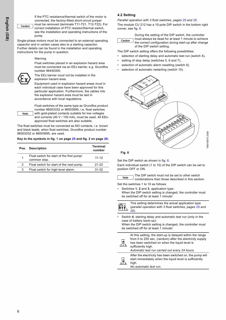
4.2 Setting
Parallel operation with 3 float switches, pages 25 and 26.
The module CU 212 has a 10-pole DIP switch in the bottom right corner, see fig. 6.
The DIP switch setting offers the following possibilities:
• selection of starting delay and automatic test run (switch 4),
• setting of stop delay (switches 5, 6 and 7),
• selection of automatic alarm resetting (switch 9),
• selection of automatic restarting (switch 10).
Fig. 6
Set the DIP switch as shown in fig. 6.
Each individual switch (1 to 10) of the DIP switch can be set to position OFF or ON.
Set the switches 1 to 10 as follows:
• Switches 1, 2 and 3, application type:When the DIP switch setting is changed, the controller must be switched off for at least 1 minute!
• Switch 4, starting delay and automatic test run (only in the case of battery back-up):When the DIP switch setting is changed, the controller must be switched off for at least 1 minute!
Caution
If the PTC resistance/thermal switch of the motor is connected, the factory-fitted short-circuit jumper must be removed (terminals T11-T21, T12-T22). For correct installation of PTC resistor/thermal switch, see the installation and operating instructions of the pump.
Warning
Float switches placed in an explosion hazard area must be connected via an EEx barrier, e.g. Grundfos number 96440300.
The EEx barrier must not be installed in the explosion hazard area.
Equipment used in explosion hazard areas must in each individual case have been approved for this particular application. Furthermore, the cables into the explosion hazard area must be laid in accordance with local regulations.
Note
Float switches of the same type as Grundfos product number 96003332 or 96003695, i.e. float switches with gold-plated contacts suitable for low voltages and currents (40 V / 100 mA), must be used. All EEx-approved float switches are also suitable.
Pos. DescriptionTerminal number
1Float switch for start of the first pump/common stop.
11-12
2 Float switch for start of the next pump. 21-22
3 Float switch for high-level alarm. 31-32
Caution
During the setting of the DIP switch, the controller must always be dead for at least 1 minute to achieve the correct configuration during start-up after change of the DIP switch setting.
TM
01
68
70
23
08
NoteThe DIP switch must not be set to other switch combinations than those described in this section.
This setting determines the actual application type (parallel operation with 3 float switches, pages 25 and 26).
At this setting, the start-up is delayed within the range from 0 to 255 sec. (random) after the electricity supply has been switched on when the liquid level is sufficiently high.Automatic test run carried out every 24 hours.
After the electricity has been switched on, the pump will start immediately when the liquid level is sufficiently high.No automatic test run.
6

En
gli
sh
(G
B)
• Switches 5, 6 and 7, stop delay:When the DIP switch setting is changed, the controller must be switched off for at least 1 minute!
• Switch 8:When the DIP switch setting is changed, the controller must be switched off for at least 1 minute!
• Switch 9, automatic alarm resetting:When the DIP switch setting is changed, the controller must be switched off for at least 1 minute!
• Switch 10, automatic restarting:When the DIP switch setting is changed, the controller must be switched off for at least 1 minute!
AC/DC selector:
The AC/DC selector switch for electrodes and/or float switches is placed as shown in fig. 7.
Fig. 7
The stop delay is the time from the stop signal is given until the pump is stopped. It must be ensured that the pump is not running dry.
0 sec. 60 sec.
15 sec. 90 sec.
30 sec. 120 sec.
45 sec. 180 sec.
Switch 8 has no function in connection with the actual application (parallel operation with 3 float switches, pages 25 and 26), but this setting must be maintained!
This setting ensures automatic resetting of alarm signals to external alarm devices and the built-in buzzer. However, an alarm signal will only be reset if the cause of the fault no longer exists.
At this setting, the alarm signal must be reset manually by means of the reset button (the reset button is described in section 4.5).
This setting enables automatic restarting after the PTC resistance/thermal switch of the motor has cut out the pump. Restarting will not be carried out until the motor has cooled to normal temperature.
When the pumps connected are used in explosion hazard areas, switch 10 must not be in this position!
At this setting, the pump must be restarted manually after the PTC resistance/thermal switch of the motor has cut out the pump. To restart the pump, push the ON-OFF-AUTO selector switch into position OFF for a short period (the ON-OFF-AUTO selector switch is described in section 4.5).
When the pumps connected are used in explosion hazard areas, switch 10 must be in this position!
TM
02
57
47
39
02
Operation with electrodes and float switches:
Selector switch in position AC:
It is possible to connect 3 electrodes (1 as reference electrode) and 2 float switches.The controller transmits a 13 to 18 VAC signal.
Operation with float switches:
Selector switch in position AC:
It is possible to connect 4 float switches.The controller transmits a 13 to 18 VAC signal.
Operation with float switches:
Selector switch in position DC:
It is possible to connect 4 float switches. Cables of up to 100 metres can be connected between the controller and the float switches.The controller transmits a 12 VDC signal.
Note
If the distance between the controller and pit exceeds 20 metres, it is not advisable to use electrodes as problems with the signal values sent back to the controller may arise.
In such cases, it is recommended to use float switches.
AC 1 2
13-18 VAC 0 V
AC DC
G 3 4
AC 1 2
13-18 VAC 0 V
AC DC
G 3 4
AC 1 2
12 VDC 0 V
AC DC
G 3 4
7

En
glis
h (G
B)
4.3 Control panel
Parallel operation with 3 float switches, pages 25 and 26.
Figure 8 shows the control panel of the CU 212 module.
Fig. 8
Key to the symbols in fig. 8:
4.4 Battery back-up functions
Parallel operation with 3 float switches, pages 25 and 26.
If a back-up battery for CU 212 (accessory for certain variants) is installed, the following functions will be carried out if the normal electricity supply to the LCD 108 fails (see also the illustrations below):
• The common alarm is active, the red indicator light is on - cannot be reset!
• If the external alarm device for common alarm is supplied from an external power source, this device will be active - cannot be reset by means of the reset button!
• The built-in buzzer (only certain variants) is activated - can be reset by means of the reset button!
• If the liquid level in the pit rises above the level for high-level alarm, the top orange indicator light will be flashing and the second orange indicator light from the top will be permanently on.
• If the starting delay function and automatic test run were selected (switch 4 of the DIP switch), the start-up will be delayed after the electricity supply has been switched on when the liquid level is sufficiently high, see section 4.2.
The table below shows the situations which may occur if the normal electricity supply to the LCD 108 fails and a back-up battery is connected:
= the indicator light is off.
= the indicator light is on.
= the indicator light is flashing.
TM
01
63
97
39
02
Pos. Description
1Green indicator light for pump 1 and 2, indicating starting delay (flashing) and pump operation (permanently on).
2
Red indicator light for pump 1 and 2, indicating pump fault.Flashing: Fault in PTC resistor/thermal switchOn: Fault in motor-protective circuit breaker.
3Red indicator light, indicating wrong phase sequence (only certain variants and three-phase pumps only).
4 Red indicator light, indicating common alarm.
5ON-OFF-AUTO selector switch for pump 1, three positions, see section 4.5.
6ON-OFF-AUTO selector switch for pump 2, three positions, see section 4.5.
7Reset button, push-button for manual resetting of alarm signals to external alarm devices and the built-in buzzer (only certain variants), see section 4.5.
8Orange indicator light, which is activated by the float switch for start of the first pump/common stop.
9Orange indicator light, which is activated by the float switch for start of the next pump.
10 and 11
Two orange indicator lights, which are activated by the float switch for high-level alarm. In case of high-level alarm, the top indicator light is flashing and the other is permanently on.
12Green indicator light, indicating that the electricity supply has been switched on.
CU 21221
1
2
1 2 3 4
7
5 6
1211
98
10
Mains supply failure:• The common alarm is active.
The red indicator light is on. • The green indicator light (electricity
supply switched on) is off.
Mains supply failure and high-level alarm:• The common alarm is active.
The red indicator light is on.• The top orange indicator light is
flashing.• The second orange indicator light from
the top is on.• The green indicator light (electricity
supply switched on) is off.
1CU 2122
CU 2122
1
8
En
gli
sh
(G
B)
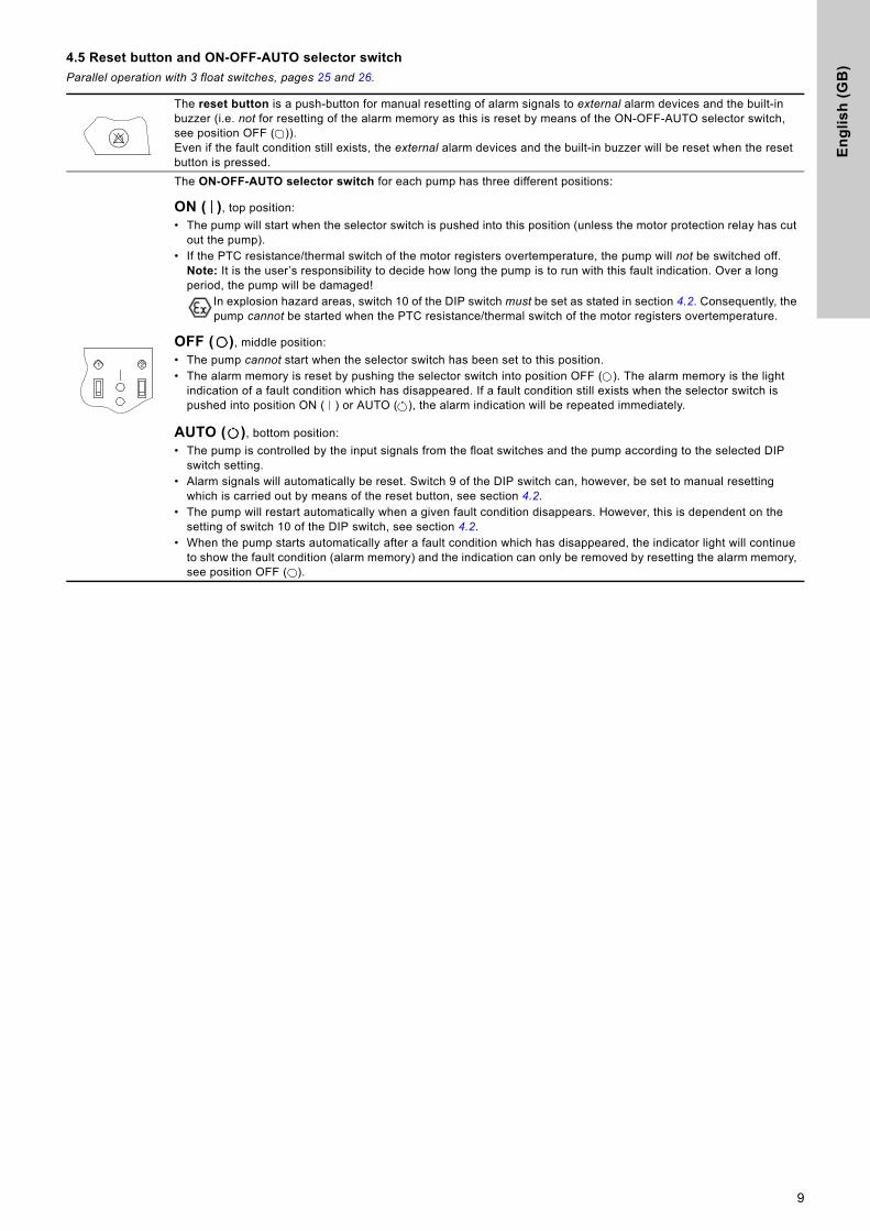
4.5 Reset button and ON-OFF-AUTO selector switch
Parallel operation with 3 float switches, pages 25 and 26.
The reset button is a push-button for manual resetting of alarm signals to external alarm devices and the built-in buzzer (i.e. not for resetting of the alarm memory as this is reset by means of the ON-OFF-AUTO selector switch, see position OFF ( )).Even if the fault condition still exists, the external alarm devices and the built-in buzzer will be reset when the reset button is pressed.
The ON-OFF-AUTO selector switch for each pump has three different positions:
ON ( ), top position:
• The pump will start when the selector switch is pushed into this position (unless the motor protection relay has cut out the pump).
• If the PTC resistance/thermal switch of the motor registers overtemperature, the pump will not be switched off.Note: It is the user’s responsibility to decide how long the pump is to run with this fault indication. Over a long period, the pump will be damaged!
In explosion hazard areas, switch 10 of the DIP switch must be set as stated in section 4.2. Consequently, the pump cannot be started when the PTC resistance/thermal switch of the motor registers overtemperature.
OFF ( ), middle position:
• The pump cannot start when the selector switch has been set to this position.• The alarm memory is reset by pushing the selector switch into position OFF ( ). The alarm memory is the light
indication of a fault condition which has disappeared. If a fault condition still exists when the selector switch is pushed into position ON ( ) or AUTO ( ), the alarm indication will be repeated immediately.
AUTO ( ), bottom position:
• The pump is controlled by the input signals from the float switches and the pump according to the selected DIP switch setting.
• Alarm signals will automatically be reset. Switch 9 of the DIP switch can, however, be set to manual resetting which is carried out by means of the reset button, see section 4.2.
• The pump will restart automatically when a given fault condition disappears. However, this is dependent on the setting of switch 10 of the DIP switch, see section 4.2.
• When the pump starts automatically after a fault condition which has disappeared, the indicator light will continue to show the fault condition (alarm memory) and the indication can only be removed by resetting the alarm memory, see position OFF ( ).
21
9
En
glis
h (G
B)
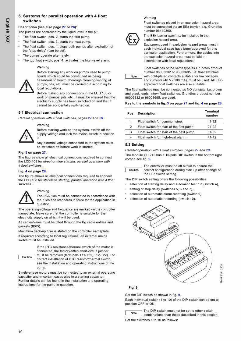
5. Systems for parallel operation with 4 float switches
Description (see also page 27 or 28):
The pumps are controlled by the liquid level in the pit.
• The float switch, pos. 2, starts the first pump.
• The float switch, pos. 3, starts the next pump.
• The float switch, pos. 1, stops both pumps after expiration of the "stop delay" (can be set).
• The pumps operate alternately.
• The top float switch, pos. 4, activates the high-level alarm.
5.1 Electrical connection
Parallel operation with 4 float switches, pages 27 and 28.
Fig. 3 on page 27.
The figures show all electrical connections required to connect the LCD 108 for direct-on-line starting, parallel operation with 4 float switches.
Fig. 4 on page 28.
The figure shows all electrical connections required to connect the LCD 108 for star-delta starting, parallel operation with 4 float switches.
The operating voltage and frequency are marked on the controller nameplate. Make sure that the controller is suitable for the electricity supply on which it will be used.
All cables/wires must be fitted through the Pg cable entries and gaskets (IP65).
Maximum back-up fuse is stated on the controller nameplate.
If required according to local regulations, an external mains switch must be installed.
Single-phase motors must be connected to an external operating capacitor and in certain cases also to a starting capacitor. Further details can be found in the installation and operating instructions for the pump in question.
The float switches must be connected as NO contacts, i.e. brown and black leads, when float switches, Grundfos product number 96003332 or 96003695, are used.
Key to the symbols in fig. 3 on page 27 and fig. 4 on page 28:
5.2 Setting
Parallel operation with 4 float switches, pages 27 and 28.
The module CU 212 has a 10-pole DIP switch in the bottom right corner, see fig. 9.
The DIP switch setting offers the following possibilities:
• selection of starting delay and automatic test run (switch 4),
• setting of stop delay (switches 5, 6 and 7),
• selection of automatic alarm resetting (switch 9),
• selection of automatic restarting (switch 10).
Fig. 9
Set the DIP switch as shown in fig. 9.
Each individual switch (1 to 10) of the DIP switch can be set to position OFF or ON.
Set the switches 1 to 10 as follows:
Warning
Before starting any work on pumps used to pump liquids which could be constituted as being hazardous to health, thorough cleaning/venting of pumps, pits, etc. must be carried out according to local regulations.
Before making any connections in the LCD 108 or work on pumps, pits, etc., it must be ensured that the electricity supply has been switched off and that it cannot be accidentally switched on.
Warning
Before starting work on the system, switch off the supply voltage and lock the mains switch in position 0.
Any external voltage connected to the system must be switched off before work is started.
Warning
The LCD 108 must be connected in accordance with the rules and standards in force for the application in question.
Caution
If the PTC resistance/thermal switch of the motor is connected, the factory-fitted short-circuit jumper must be removed (terminals T11-T21, T12-T22). For correct installation of PTC resistor/thermal switch, see the installation and operating instructions of the pump.
Warning
Float switches placed in an explosion hazard area must be connected via an EEx barrier, e.g. Grundfos number 96440300.
The EEx barrier must not be installed in the explosion hazard area.
Equipment used in explosion hazard areas must in each individual case have been approved for this particular application. Furthermore, the cables into the explosion hazard area must be laid in accordance with local regulations.
Note
Float switches of the same type as Grundfos product number 96003332 or 96003695, i.e. float switches with gold-plated contacts suitable for low voltages and currents (40 V / 100 mA), must be used. All EEx-approved float switches are also suitable.
Pos. DescriptionTerminal number
1 Float switch for common stop. 11-12
2 Float switch for start of the first pump. 21-22
3 Float switch for start of the next pump. 31-32
4 Float switch for high-level alarm. 41-42
CautionThe controller must be off circuit to ensure the correct configuration during start-up after change of the DIP switch setting.
TM
04
23
41
23
08
NoteThe DIP switch must not be set to other switch combinations than those described in this section.
10

En
gli
sh
(G
B)
• Switches 1, 2 and 3, application type:When the DIP switch setting is changed, the controller must be switched off for at least 1 minute!
• Switch 4, starting delay and automatic test run (only in the case of battery back-up):When the DIP switch setting is changed, the controller must be switched off for at least 1 minute!
• Switches 5, 6 and 7, stop delay:When the DIP switch setting is changed, the controller must be switched off for at least 1 minute!
• Switch 8:When the DIP switch setting is changed, the controller must be switched off for at least 1 minute!
• Switch 9, automatic alarm resetting:When the DIP switch setting is changed, the controller must be switched off for at least 1 minute!
• Switch 10, automatic restarting:When the DIP switch setting is changed, the controller must be switched off for at least 1 minute!
AC/DC selector:
The AC/DC selector switch for electrodes and/or float switches is placed as shown in fig. 10.
Fig. 10
This setting determines the actual application type (parallel operation with 4 float switches, pages 27 and 28).
At this setting, the start-up is delayed within the range from 0 to 255 sec. (random) after the electricity supply has been switched on when the liquid level is sufficiently high.Automatic test run carried out every 24 hours.
After the electricity has been switched on, the pump will start immediately when the liquid level is sufficiently high.No automatic test run.
The stop delay is the time from the stop signal is given until the pump is stopped. It must be ensured that the pump is not running dry.
0 sec. 60 sec.
15 sec. 90 sec.
30 sec. 120 sec.
45 sec. 180 sec.
Switch 8 has no function in connection with the actual application (parallel operation with 4 float switches, pages 27 and 28), but this setting must be maintained!
This setting ensures automatic resetting of alarm signals to external alarm devices and the built-in buzzer. However, an alarm signal will only be reset if the cause of the fault no longer exists.
At this setting, the alarm signal must be reset manually by means of the reset button (the reset button is described in section 5.5).
This setting enables automatic restarting after the PTC resistance/thermal switch of the motor has cut out the pump. Restarting will not be carried out until the motor has cooled to normal temperature.
When the pumps connected are used in explosion hazard areas, switch 10 must not be in this position!
At this setting, the pump must be restarted manually after the PTC resistance/thermal switch of the motor has cut out the pump. To restart the pump, push the ON-OFF-AUTO selector switch into position OFF for a short period (the ON-OFF-AUTO selector switch is described in section 5.5).
When the pumps connected are used in explosion hazard areas, switch 10 must be in this position!
TM
02
57
47
39
02
Operation with electrodes and float switches:
Selector switch in position AC:
It is possible to connect 3 electrodes (1 as reference electrode) and 2 float switches.The controller transmits a 13 to 18 VAC signal.
Operation with float switches:
Selector switch in position AC:
It is possible to connect 4 float switches.The controller transmits a 13 to 18 VAC signal.
Operation with float switches:
Selector switch in position DC:
It is possible to connect 4 float switches. Cables of up to 100 metres can be connected between the controller and the float switches.The controller transmits a 12 VDC signal.
Note
If the distance between the controller and pit exceeds 20 metres, it is not advisable to use electrodes as problems with the signal values sent back to the controller may arise.
In such cases, it is recommended to use float switches.
AC 1 2
13-18 VAC 0 V
AC DC
G 3 4
AC 1 2
13-18 VAC 0 V
AC DC
G 3 4
AC 1 2
12 VDC 0 V
AC DC
G 3 4
11
En
glis
h (G
B)
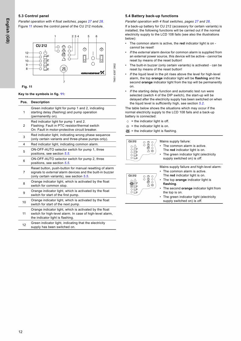
5.3 Control panel
Parallel operation with 4 float switches, pages 27 and 28.
Figure 11 shows the control panel of the CU 212 module.
Fig. 11
Key to the symbols in fig. 11:
5.4 Battery back-up functions
Parallel operation with 4 float switches, pages 27 and 28.
If a back-up battery for CU 212 (accessory for certain variants) is installed, the following functions will be carried out if the normal electricity supply to the LCD 108 fails (see also the illustrations below):
• The common alarm is active, the red indicator light is on - cannot be reset!
• If the external alarm device for common alarm is supplied from an external power source, this device will be active - cannot be reset by means of the reset button!
• The built-in buzzer (only certain variants) is activated - can be reset by means of the reset button!
• If the liquid level in the pit rises above the level for high-level alarm, the top orange indicator light will be flashing and the second orange indicator light from the top will be permanently on.
• If the starting delay function and automatic test run were selected (switch 4 of the DIP switch), the start-up will be delayed after the electricity supply has been switched on when the liquid level is sufficiently high, see section 5.2.
The table below shows the situations which may occur if the normal electricity supply to the LCD 108 fails and a back-up battery is connected:
= the indicator light is off.
= the indicator light is on.
= the indicator light is flashing.
TM
01
63
97
39
02
Pos. Description
1Green indicator light for pump 1 and 2, indicating starting delay (flashing) and pump operation (permanently on).
2Red indicator light for pump 1 and 2.Flashing: Fault in PTC resistor/thermal switchOn: Fault in motor-protective circuit breaker.
3Red indicator light, indicating wrong phase sequence (only certain variants and three-phase pumps only).
4 Red indicator light, indicating common alarm.
5ON-OFF-AUTO selector switch for pump 1, three positions, see section 5.5.
6ON-OFF-AUTO selector switch for pump 2, three positions, see section 5.5.
7Reset button, push-button for manual resetting of alarm signals to external alarm devices and the built-in buzzer (only certain variants), see section 5.5.
8Orange indicator light, which is activated by the float switch for common stop.
9Orange indicator light, which is activated by the float switch for start of the first pump.
10Orange indicator light, which is activated by the float switch for start of the next pump.
11Orange indicator light, which is activated by the float switch for high-level alarm. In case of high-level alarm, the indicator light is flashing.
12Green indicator light, indicating that the electricity supply has been switched on.
CU 21221
1
2
1 2 3 4
7
5 6
1211
98
10
Mains supply failure:• The common alarm is active.
The red indicator light is on. • The green indicator light (electricity
supply switched on) is off.
Mains supply failure and high-level alarm:• The common alarm is active.
The red indicator light is on.• The top orange indicator light is
flashing.• The second orange indicator light from
the top is on.• The green indicator light (electricity
supply switched on) is off.
1CU 2122
CU 2122
1
12

En
gli
sh
(G
B)
5.5 Reset button and ON-OFF-AUTO selector switch
Parallel operation with 4 float switches, pages 27 and 28.
The reset button is a push-button for manual resetting of alarm signals to external alarm devices and the built-in buzzer (i.e. not for resetting of the alarm memory as this is reset by means of the ON-OFF-AUTO selector switch, see position OFF ( )).Even if the fault condition still exists, the external alarm devices and the built-in buzzer will be reset when the reset button is pressed.
The ON-OFF-AUTO selector switch for each pump has three different positions:
ON ( ), top position:
• The pump will start when the selector switch is pushed into this position (unless the motor protection relay has cut out the pump).
• If the PTC resistance/thermal switch of the motor registers overtemperature, the pump will not be switched off.Note: It is the user’s responsibility to decide how long the pump is to run with this fault indication. Over a long period, the pump will be damaged!
In explosion hazard areas, switch 10 of the DIP switch must be set as stated in section 5.2. Consequently, the pump cannot be started when the PTC resistance/thermal switch of the motor registers overtemperature.
OFF ( ), middle position:
• The pump cannot start when the selector switch has been set to this position.• The alarm memory is reset by pushing the selector switch into position OFF ( ). The alarm memory is the light
indication of a fault condition which has disappeared. If a fault condition still exists when the selector switch is pushed into position ON ( ) or AUTO ( ), the alarm indication will be repeated immediately.
AUTO ( ), bottom position:
• The pump is controlled by the input signals from the float switches and the pump according to the selected DIP switch setting.
• Alarm signals will automatically be reset. Switch 9 of the DIP switch can, however, be set to manual resetting which is carried out by means of the reset button, see section 5.2.
• The pump will restart automatically when a given fault condition disappears. However, this is dependent on the setting of switch 10 of the DIP switch, see section 5.2.
• When the pump starts automatically after a fault condition which has disappeared, the indicator light will continue to show the fault condition (alarm memory) and the indication can only be removed by resetting the alarm memory, see position OFF ( ).
21
13
En
glis
h (G
B)
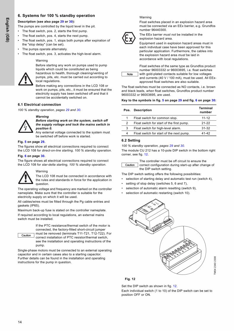
6. Systems for 100 % standby operation
Description (see also page 29 or 30):
The pumps are controlled by the liquid level in the pit.
• The float switch, pos. 2, starts the first pump.
• The float switch, pos. 4, starts the next pump.
• The float switch, pos. 1, stops both pumps after expiration of the "stop delay" (can be set).
• The pumps operate alternately.
• The float switch, pos. 3, activates the high-level alarm.
6.1 Electrical connection
100 % standby operation, pages 29 and 30.
Fig. 5 on page 29.
The figures show all electrical connections required to connect the LCD 108 for direct-on-line starting, 100 % standby operation.
Fig. 6 on page 30.
The figure shows all electrical connections required to connect the LCD 108 for star-delta starting, 100 % standby operation.
The operating voltage and frequency are marked on the controller nameplate. Make sure that the controller is suitable for the electricity supply on which it will be used.
All cables/wires must be fitted through the Pg cable entries and gaskets (IP65).
Maximum back-up fuse is stated on the controller nameplate.
If required according to local regulations, an external mains switch must be installed.
Single-phase motors must be connected to an external operating capacitor and in certain cases also to a starting capacitor. Further details can be found in the installation and operating instructions for the pump in question.
The float switches must be connected as NO contacts, i.e. brown and black leads, when float switches, Grundfos product number 96003332 or 96003695, are used.
Key to the symbols in fig. 5 on page 29 and fig. 6 on page 30:
6.2 Setting
100 % standby operation, pages 29 and 30.
The module CU 212 has a 10-pole DIP switch in the bottom right corner, see fig. 12.
The DIP switch setting offers the following possibilities:
• selection of starting delay and automatic test run (switch 4),
• setting of stop delay (switches 5, 6 and 7),
• selection of automatic alarm resetting (switch 9),
• selection of automatic restarting (switch 10).
Fig. 12
Set the DIP switch as shown in fig. 12.
Each individual switch (1 to 10) of the DIP switch can be set to position OFF or ON.
Warning
Before starting any work on pumps used to pump liquids which could be constituted as being hazardous to health, thorough cleaning/venting of pumps, pits, etc. must be carried out according to local regulations.
Before making any connections in the LCD 108 or work on pumps, pits, etc., it must be ensured that the electricity supply has been switched off and that it cannot be accidentally switched on.
WarningBefore starting work on the system, switch off the supply voltage and lock the mains switch in position 0.Any external voltage connected to the system must be switched off before work is started.
Warning
The LCD 108 must be connected in accordance with the rules and standards in force for the application in question.
Caution
If the PTC resistance/thermal switch of the motor is connected, the factory-fitted short-circuit jumper must be removed (terminals T11-T21, T12-T22). For correct installation of PTC resistor/thermal switch, see the installation and operating instructions of the pump.
Warning
Float switches placed in an explosion hazard area must be connected via an EEx barrier, e.g. Grundfos number 96440300.
The EEx barrier must not be installed in the explosion hazard area.
Equipment used in explosion hazard areas must in each individual case have been approved for this particular application. Furthermore, the cables into the explosion hazard area must be laid in accordance with local regulations.
Note
Float switches of the same type as Grundfos product number 96003332 or 96003695, i.e. float switches with gold-plated contacts suitable for low voltages and currents (40 V / 100 mA), must be used. All EEx-approved float switches are also suitable.
Pos. DescriptionTerminal number
1 Float switch for common stop. 11-12
2 Float switch for start of the first pump. 21-22
3 Float switch for high-level alarm. 31-32
4 Float switch for start of the next pump. 41-42
CautionThe controller must be off circuit to ensure the correct configuration during start-up after change of the DIP switch setting.
TM
04
23
40
23
08
14

En
gli
sh
(G
B)
Set the switches 1 to 10 as follows:
• Switches 1, 2 and 3, application type:When the DIP switch setting is changed, the controller must be switched off for at least 1 minute!
• Switch 4, starting delay and automatic test run (only in the case of battery back-up):When the DIP switch setting is changed, the controller must be switched off for at least 1 minute!
• Switches 5, 6 and 7, stop delay:When the DIP switch setting is changed, the controller must be switched off for at least 1 minute!
• Switch 8:When the DIP switch setting is changed, the controller must be switched off for at least 1 minute!
• Switch 9, automatic alarm resetting:When the DIP switch setting is changed, the controller must be switched off for at least 1 minute!
• Switch 10, automatic restarting:When the DIP switch setting is changed, the controller must be switched off for at least 1 minute!
AC/DC selector:
The AC/DC selector switch for electrodes and/or float switches is placed as shown in fig. 13.
Fig. 13
NoteThe DIP switch must not be set to other switch combinations than those described in this section.
This setting determines the actual application type (100 % standby operation, pages 29 and 30).
At this setting, the start-up is delayed within the range from 0 to 255 sec. (random) after the electricity supply has been switched on when the liquid level is sufficiently high.Automatic test run carried out every 24 hours.
After the electricity has been switched on, the pump will start immediately when the liquid level is sufficiently high.No automatic test run.
The stop delay is the time from the stop signal is given until the pump is stopped. It must be ensured that the pump is not running dry.
0 sec. 60 sec.
15 sec. 90 sec.
30 sec. 120 sec.
45 sec. 180 sec.
Switch 8 has no function in connection with the actual application (100 % standby operation, pages 29 and 30), but this setting must be maintained!
This setting ensures automatic resetting of alarm signals to external alarm devices and the built-in buzzer. However, an alarm signal will only be reset if the cause of the fault no longer exists.
At this setting, the alarm signal must be reset manually by means of the reset button (the reset button is described in section 6.5).
This setting enables automatic restarting after the PTC resistance/thermal switch of the motor has cut out the pump. Restarting will not be carried out until the motor has cooled to normal temperature.
When the pumps connected are used in explosion hazard areas, switch 10 must not be in this position!
At this setting, the pump must be restarted manually after the PTC resistance/thermal switch of the motor has cut out the pump. To restart the pump, push the ON-OFF-AUTO selector switch into position OFF for a short period (the ON-OFF-AUTO selector switch is described in section 6.5).
When the pumps connected are used in explosion hazard areas, switch 10 must be in this position!
TM
02
57
47
39
02
Operation with electrodes and float switches:
Selector switch in position AC:
It is possible to connect 3 electrodes (1 as reference electrode) and 2 float switches.The controller transmits a 13 to 18 VAC signal.
Operation with float switches:
Selector switch in position AC:
It is possible to connect 4 float switches.The controller transmits a 13 to 18 VAC signal.
Operation with float switches:
Selector switch in position DC:
It is possible to connect 4 float switches. Cables of up to 100 metres can be connected between the controller and the float switches.The controller transmits a 12 VDC signal.
Note
If the distance between the controller and pit exceeds 20 metres, it is not advisable to use electrodes as problems with the signal values sent back to the controller may arise.
In such cases, it is recommended to use float switches.
AC 1 2
13-18 VAC 0 V
AC DC
G 3 4
AC 1 2
13-18 VAC 0 V
AC DC
G 3 4
AC 1 2
12 VDC 0 V
AC DC
G 3 4
15

En
glis
h (G
B)
6.3 Control panel
100 % standby operation, pages 29 and 30.
Figure 14 shows the control panel of the CU 212 module.
Fig. 14
Key to the symbols in fig. 14:
6.4 Battery back-up functions
100 % standby operation, pages 29 and 30.
If a back-up battery for CU 212 (accessory for certain variants) is installed, the following functions will be carried out if the normal electricity supply to the LCD 108 fails (see also the illustrations below):
• The common alarm is active, the red indicator light is on - cannot be reset!
• If the external alarm device for common alarm is supplied from an external power source, this device will be active - cannot be reset by means of the reset button!
• The built-in buzzer (only certain variants) is activated - can be reset by means of the reset button!
• If the liquid level in the pit rises above the level for high-level alarm, the second orange indicator light from the top will be flashing. If the liquid level is higher than the level for start of the next pump, the top orange indicator light will be permanently on.
• If the starting delay function and automatic test run were selected (switch 4 of the DIP switch), the start-up will be delayed after the electricity supply has been switched on when the liquid level is sufficiently high, see section 6.2.
The table below shows the situations which may occur if the normal electricity supply to the LCD 108 fails and a back-up battery is connected:
= the indicator light is off.
= the indicator light is on.
= the indicator light is flashing.
TM
01
63
97
39
02
Pos. Description
1Green indicator light for pump 1 and 2, indicating starting delay (flashing) and pump operation (permanently on).
2Red indicator light for pump 1 and 2.Flashing: Fault in PTC resistor/thermal switchOn: Fault in motor-protective circuit breaker.
3Red indicator light, indicating wrong phase sequence (only certain variants and three-phase pumps only).
4 Red indicator light, indicating common alarm.
5ON-OFF-AUTO selector switch for pump 1, three positions, see section 6.5.
6ON-OFF-AUTO selector switch for pump 2, three positions, see section 6.5.
7Reset button, push-button for manual resetting of alarm signals to external alarm devices and the built-in buzzer (only certain variants), see section 6.5.
8Orange indicator light, which is activated by the float switch for common stop.
9Orange indicator light, which is activated by the float switch for start of the first pump.
10Orange indicator light, which is activated by the float switch for high-level alarm. In case of high-level alarm, the indicator light is flashing.
11Orange indicator light, which is activated by the float switch for start of the next pump.
12Green indicator light, indicating that the electricity supply has been switched on.
CU 21221
1
2
1 2 3 4
7
5 6
1211
98
10
Mains supply failure:• The common alarm is active.
The red indicator light is on. • The green indicator light (electricity
supply switched on) is off.
Mains supply failure and high-level alarm:• The common alarm is active.
The red indicator light is on.• The top orange indicator light is on.• The second orange indicator light from
the top is flashing.• The green indicator light (electricity
supply switched on) is off.
1CU 2122
CU 2122
1
16

En
gli
sh
(G
B)
6.5 Reset button and ON-OFF-AUTO selector switch
100 % standby operation, pages 29 and 30.
The reset button is a push-button for manual resetting of alarm signals to external alarm devices and the built-in buzzer (i.e. not for resetting of the alarm memory as this is reset by means of the ON-OFF-AUTO selector switch, see position OFF ( )).Even if the fault condition still exists, the external alarm devices and the built-in buzzer will be reset when the reset button is pressed.
The ON-OFF-AUTO selector switch for each pump has three different positions:
ON ( ), top position:
• The pump will start when the selector switch is pushed into this position (unless the motor protection relay has cut out the pump).
• If the PTC resistance/thermal switch of the motor registers overtemperature, the pump will not be switched off.Note: It is the user’s responsibility to decide how long the pump is to run with this fault indication. Over a long period, the pump will be damaged!
In explosion hazard areas, switch 10 of the DIP switch must be set as stated in section 6.2. Consequently, the pump cannot be started when the PTC resistance/thermal switch of the motor registers overtemperature.
OFF ( ), middle position:
• The pump cannot start when the selector switch has been set to this position.• The alarm memory is reset by pushing the selector switch into position OFF ( ). The alarm memory is the light
indication of a fault condition which has disappeared. If a fault condition still exists when the selector switch is pushed into position ON ( ) or AUTO ( ), the alarm indication will be repeated immediately.
AUTO ( ), bottom position:
• The pump is controlled by the input signals from the float switches and the pump according to the selected DIP switch setting.
• Alarm signals will automatically be reset. Switch 9 of the DIP switch can, however, be set to manual resetting which is carried out by means of the reset button, see section 6.2.
• The pump will restart automatically when a given fault condition disappears. However, this is dependent on the setting of switch 10 of the DIP switch, see section 6.2.
• When the pump starts automatically after a fault condition which has disappeared, the indicator light will continue to show the fault condition (alarm memory) and the indication can only be removed by resetting the alarm memory, see position OFF ( ).
21
17
En
glis
h (G
B)
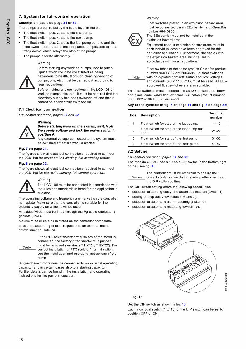
7. System for full-control operation
Description (see also page 31 or 32):
The pumps are controlled by the liquid level in the pit.
• The float switch, pos. 3, starts the first pump.
• The float switch, pos. 4, starts the next pump.
• The float switch, pos. 2, stops the last pump but one and the float switch, pos. 1, stops the last pump. It is possible to set a "stop delay" which delays the stop of the pumps.
• The pumps operate alternately.
7.1 Electrical connection
Full-control operation, pages 31 and 32.
Fig. 7 on page 31.
The figures show all electrical connections required to connect the LCD 108 for direct-on-line starting, full-control operation.
Fig. 8 on page 32.
The figure shows all electrical connections required to connect the LCD 108 for star-delta starting, full-control operation.
The operating voltage and frequency are marked on the controller nameplate. Make sure that the controller is suitable for the electricity supply on which it will be used.
All cables/wires must be fitted through the Pg cable entries and gaskets (IP65).
Maximum back-up fuse is stated on the controller nameplate.
If required according to local regulations, an external mains switch must be installed.
Single-phase motors must be connected to an external operating capacitor and in certain cases also to a starting capacitor. Further details can be found in the installation and operating instructions for the pump in question.
The float switches must be connected as NO contacts, i.e. brown and black leads, when float switches, Grundfos product number 96003332 or 96003695, are used.
Key to the symbols in fig. 7 on page 31 and fig. 8 on page 32:
7.2 Setting
Full-control operation, pages 31 and 32.
The module CU 212 has a 10-pole DIP switch in the bottom right corner, see fig. 15.
The DIP switch setting offers the following possibilities:
• selection of starting delay and automatic test run (switch 4),
• setting of stop delay (switches 5, 6 and 7),
• selection of automatic alarm resetting (switch 9),
• selection of automatic restarting (switch 10).
Fig. 15
Set the DIP switch as shown in fig. 15.
Each individual switch (1 to 10) of the DIP switch can be set to position OFF or ON.
Warning
Before starting any work on pumps used to pump liquids which could be constituted as being hazardous to health, thorough cleaning/venting of pumps, pits, etc. must be carried out according to local regulations.
Before making any connections in the LCD 108 or work on pumps, pits, etc., it must be ensured that the electricity supply has been switched off and that it cannot be accidentally switched on.
WarningBefore starting work on the system, switch off the supply voltage and lock the mains switch in position 0.Any external voltage connected to the system must be switched off before work is started.
Warning
The LCD 108 must be connected in accordance with the rules and standards in force for the application in question.
Caution
If the PTC resistance/thermal switch of the motor is connected, the factory-fitted short-circuit jumper must be removed (terminals T11-T21, T12-T22). For correct installation of PTC resistor/thermal switch, see the installation and operating instructions of the pump.
Warning
Float switches placed in an explosion hazard area must be connected via an EEx barrier, e.g. Grundfos number 96440300.The EEx barrier must not be installed in the explosion hazard area.
Equipment used in explosion hazard areas must in each individual case have been approved for this particular application. Furthermore, the cables into the explosion hazard area must be laid in accordance with local regulations.
Note
Float switches of the same type as Grundfos product number 96003332 or 96003695, i.e. float switches with gold-plated contacts suitable for low voltages and currents (40 V / 100 mA), must be used. All EEx-approved float switches are also suitable.
Pos. DescriptionTerminal number
1 Float switch for stop of the last pump. 11-12
2Float switch for stop of the last pump but one.
21-22
3 Float switch for start of the first pump. 31-32
4 Float switch for start of the next pump. 41-42
CautionThe controller must be off circuit to ensure the correct configuration during start-up after change of the DIP switch setting.
TM
04
23
42
23
08
18

En
gli
sh
(G
B)
Set the switches 1 to 10 as follows:
• Switches 1, 2 and 3, application type:When the DIP switch setting is changed, the controller must be switched off for at least 1 minute!
• Switch 4, starting delay and automatic test run (only in the case of battery back-up):When the DIP switch setting is changed, the controller must be switched off for at least 1 minute!
• Switches 5, 6 and 7, stop delay:When the DIP switch setting is changed, the controller must be switched off for at least 1 minute!
* The stop delay applies to both stop float switches, pos. 1 and 2, on pages 31 and 32. If the two stop float switches are placed so close to each other that the stop delay for the upper stop float switch has not expired before the liquid level reached the lower stop float switch, then both pumps will not be stopped until the stop delay for the lower float switch has expired.
• Switch 8:When the DIP switch setting is changed, the controller must be switched off for at least 1 minute!
• Switch 9, automatic alarm resetting:When the DIP switch setting is changed, the controller must be switched off for at least 1 minute!
• Switch 10, automatic restarting:When the DIP switch setting is changed, the controller must be switched off for at least 1 minute!
AC/DC selector:
The AC/DC selector switch for electrodes and/or float switches is placed as shown in fig. 16.
Fig. 16
NoteThe DIP switch must not be set to other switch combinations than those described in this section.
This setting determines the actual application type (full-control operation, pages 31 and 32).
At this setting, the start-up is delayed within the range from 0 to 255 sec. (random) after the electricity supply has been switched on when the liquid level is sufficiently high.Automatic test run carried out every 24 hours.
After the electricity has been switched on, the pump will start immediately when the liquid level is sufficiently high.No automatic test run.
The stop delay is the time from the stop signal is given until the pump is stopped.* It must be ensured that the pump is not running dry.
0 sec. 60 sec.
15 sec. 90 sec.
30 sec. 120 sec.
45 sec. 180 sec.
Switch 8 has no function in connection with the actual application (full-control operation, pages 31 and 32), but this setting must be maintained!
This setting ensures automatic resetting of alarm signals to external alarm devices and the built-in buzzer. However, an alarm signal will only be reset if the cause of the fault no longer exists.
At this setting, the alarm signal must be reset manually by means of the reset button (the reset button is described in section 7.5).
This setting enables automatic restarting after the PTC resistance/thermal switch of the motor has cut out the pump. Restarting will not be carried out until the motor has cooled to normal temperature.
When the pumps connected are used in explosion hazard areas, switch 10 must not be in this position!
At this setting, the pump must be restarted manually after the PTC resistance/thermal switch of the motor has cut out the pump. To restart the pump, push the ON-OFF-AUTO selector switch into position OFF for a short period (the ON-OFF-AUTO selector switch is described in section 7.5).
When the pumps connected are used in explosion hazard areas, switch 10 must be in this position!
TM
02
57
47
39
02
Operation with electrodes and float switches:
Selector switch in position AC:
It is possible to connect 3 electrodes (1 as reference electrode) and 2 float switches.The controller transmits a 13 to 18 VAC signal.
Operation with float switches:
Selector switch in position AC:
It is possible to connect 4 float switches.The controller transmits a 13 to 18 VAC signal.
Operation with float switches:
Selector switch in position DC:
It is possible to connect 4 float switches. Cables of up to 100 metres can be connected between the controller and the float switches.The controller transmits a 12 VDC signal.
Note
If the distance between the controller and pit exceeds 20 metres, it is not advisable to use electrodes as problems with the signal values sent back to the controller may arise.
In such cases, it is recommended to use float switches.
AC 1 2
13-18 VAC 0 V
AC DC
G 3 4
AC 1 2
13-18 VAC 0 V
AC DC
G 3 4
AC 1 2
12 VDC 0 V
AC DC
G 3 4
19

En
glis
h (G
B)
7.3 Control panel
Full-control operation, pages 31 and 32.
Figure 17 shows the control panel of the CU 212 module.
Fig. 17
Key to the symbols in fig. 17:
7.4 Battery back-up functions
Full-control operation, pages 31 and 32.
If a back-up battery for CU 212 (accessory for certain variants) is installed, the following functions will be carried out if the normal electricity supply to the LCD 108 fails (see also the illustrations below):
• The common alarm is active, the red indicator light is on - cannot be reset!
• If the external alarm device for common alarm is supplied from an external power source, this device will be active - cannot be reset by means of the reset button!
• The built-in buzzer (only certain variants) is activated - can be reset by means of the reset button!
• If the starting delay function and automatic test run were selected (switch 4 of the DIP switch), the start-up will be delayed after the electricity supply has been switched on when the liquid level is sufficiently high, see section 7.2.
The table below shows the situation which may occur if the normal electricity supply to the LCD 108 fails and a back-up battery is connected:
= the indicator light is off.
= the indicator light is on.
= the indicator light is flashing.T
M0
1 6
39
7 3
90
2
Pos. Description
1Green indicator light for pump 1 and 2, indicating starting delay (flashing) and pump operation (permanently on).
2Red indicator light for pump 1 and 2.Flashing: Fault in PTC resistor/thermal switch.On: Fault in motor-protective circuit breaker.
3Red indicator light, indicating wrong phase sequence (only certain variants and three-phase pumps only).
4 Red indicator light, indicating common alarm.
5ON-OFF-AUTO selector switch for pump 1, three positions, see section 7.5.
6ON-OFF-AUTO selector switch for pump 2, three positions, see section 7.5.
7Reset button, push-button for manual resetting of alarm signals to external alarm devices and the built-in buzzer (only certain variants), see section 7.5.
8Orange indicator light, which is activated by the float switch for stop of the last pump.
9Orange indicator light, which is activated by the float switch for stop of the last pump but one.
10Orange indicator light, which is activated by the float switch for start of the first pump.
11Orange indicator light, which is activated by the float switch for start of the next pump.
12Green indicator light, indicating that the electricity supply has been switched on.
CU 21221
1
2
1 2 3 4
7
5 6
1211
98
10
Mains supply failure:• The common alarm is active.
The red indicator light is on.• The green indicator light (electricity
supply switched on) is off.
1CU 2122
20
En
gli
sh
(G
B)
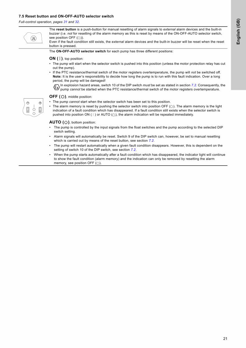
7.5 Reset button and ON-OFF-AUTO selector switch
Full-control operation, pages 31 and 32.
The reset button is a push-button for manual resetting of alarm signals to external alarm devices and the built-in buzzer (i.e. not for resetting of the alarm memory as this is reset by means of the ON-OFF-AUTO selector switch, see position OFF ( )).Even if the fault condition still exists, the external alarm devices and the built-in buzzer will be reset when the reset button is pressed.
The ON-OFF-AUTO selector switch for each pump has three different positions:
ON ( ), top position:
• The pump will start when the selector switch is pushed into this position (unless the motor protection relay has cut out the pump).
• If the PTC resistance/thermal switch of the motor registers overtemperature, the pump will not be switched off.Note: It is the user’s responsibility to decide how long the pump is to run with this fault indication. Over a long period, the pump will be damaged!
In explosion hazard areas, switch 10 of the DIP switch must be set as stated in section 7.2. Consequently, the pump cannot be started when the PTC resistance/thermal switch of the motor registers overtemperature.
OFF ( ), middle position:
• The pump cannot start when the selector switch has been set to this position.• The alarm memory is reset by pushing the selector switch into position OFF ( ). The alarm memory is the light
indication of a fault condition which has disappeared. If a fault condition still exists when the selector switch is pushed into position ON ( ) or AUTO ( ), the alarm indication will be repeated immediately.
AUTO ( ), bottom position:
• The pump is controlled by the input signals from the float switches and the pump according to the selected DIP switch setting.
• Alarm signals will automatically be reset. Switch 9 of the DIP switch can, however, be set to manual resetting which is carried out by means of the reset button, see section 7.2.
• The pump will restart automatically when a given fault condition disappears. However, this is dependent on the setting of switch 10 of the DIP switch, see section 7.2.
• When the pump starts automatically after a fault condition which has disappeared, the indicator light will continue to show the fault condition (alarm memory) and the indication can only be removed by resetting the alarm memory, see position OFF ( ).
21
21

En
glis
h (G
B)
8. Start-up
Prior to start-up, the connection and DIP switch setting must have been carried out according to sections 4. to 7.
Start-up must be carried out by authorized personnel.
Proceed as follows:
1. Check whether the float switches have been connected according to the wiring diagram for the actual application.
2. Check that the pump inlets are submerged in the liquid to be pumped.
3. Set the motor protection relays to the rated current stated on the nameplates.
4. Warning:
5. Switch on the electricity supply.Three-phase pumps only: Check for wrong phase sequence (only certain variants), (the pump cannot be started if the phase sequence is wrong!).
6. Start the pumps, see section 4.5, 5.5, 6.5 or 7.5.
7. Check that the pumps are not running dry. The risk of dry running can be eliminated by a renewed time setting by means of the DIP switch according to section 4.2, 5.2, 6.2 or 7.2 and/or by moving the float switches.
8. Three-phase pumps only: Check whether the direction of rotation of the pumps is correct according to the installation and operating instructions for the pump in question.
9. Select the required operating mode by means of the ON-OFF-AUTO selector switch, see section 4.5, 5.5, 6.5 or 7.5.
9. Maintenance
During normal application and operation, the controller LCD 108 is maintenance-free.
However, it is advisable to carry out minor checks of the LCD 108 controller, pump pits, tanks, pumps, etc. at suitable intervals. These checks should be carried out by authorized personnel.
• Check the gaskets of the LCD 108 cabinet front and those of the Pg cable entries.
• Check the cable entries for the explosion hazard area.
• Check for possible deposits/sludge build-up in the pump pit/tank. Sludge may settle in areas with almost stagnant liquid.
• Check for beginning sludge build-up around the float switches.
• Check for possible blockage on the suction side of the pump. A blockage will typically be a large solid object.
• If the LCD 108 has been installed in a particularly aggressive environment, it is advisable to check the motor protection contacts in order to identify possible chemical attack resulting in corrosion. In typical installations, the motor protection contacts will work for several years and do not require any inspection.
Warning
Before starting any work on pumps used to pump liquids which could be constituted as being hazardous to health, thorough cleaning/venting of pumps, pits, etc. must be carried out according to local regulations.
Before making any connections in the LCD 108 or work on pumps, pits, etc., it must be ensured that the electricity supply has been switched off and that it cannot be accidentally switched on.
Warning
Set the motor-protective circuit breakers to the rated current stamped on the nameplates according to the values in the table.
Conversion table for motor protection relay setting
IN IDOL Istar-delta
10 10 5.8
13 13 7.5
17 17 9.6
22 22 12.4
28 28 16.1
36 36 20.7
46 46 26.8
60 60 34.6
77 77 44.7
100 100 57.7
Warning
Before starting any work on pumps used to pump liquids which could be constituted as being hazardous to health, thorough cleaning/venting of pumps, pits, etc. must be carried out according to local regulations.
Before making any connections in the LCD 108 or work on pumps, pits, etc., it must be ensured that the electricity supply has been switched off and that it cannot be accidentally switched on.
Note
The list above is not complete. The LCD 108 may be installed in systems, installations and/or environments which require thorough and regular maintenance.
22

En
gli
sh
(G
B)
10. Technical dataVoltage variants, nominal voltages
• 1 x 230 V.
• 3 x 230 V.
• 3 x 400 V.
Voltage tolerances for LCD 108
- 15 %/+ 10 % of nominal voltage.
See also installation and operating instructions for the pump in question.
Mains frequency for LCD 108
50/60 Hz. See also installation and operating instructions for the pump in question.
Supply system earthing
For TN systems and TT systems.
Rated insulation voltage, Ui
4 kV.
Rated impulse withstand voltage, Uimp
4 kV.
Back-up fuse
Depending on variant, see nameplate.
Control circuit fuse
Direct-on-line starting:
Fine-wire fuse: 250 mA / F / 32 mm x ∅6 mm.
Star-delta starting:
Fine-wire fuse: 1 A / F / 32 mm x ∅6 mm.
Ambient temperature
• During operation: -30 to +50 °C(must not be exposed to direct sunlight).
• In stock: -30 to +60 °C.
Enclosure class
IP65.
EMC (electromagnetic compatibility)
According to EN 61 000-6-2 and EN 61 000-6-3.
Cabinet LCD 108 for direct-on-line starting
• External dimensions: Height = 410 mm, width = 278 mm, depth = 150 mm.
• Material: ABS (Acrylonitrile butadiene styrene).
• Weight: Approx. 5 kg, depending on variant, see nameplate.
Cabinet LCD 108 for star-delta starting
• External dimensions: Height = 650 mm, width = 500 mm, depth = 225 mm.
• Material: Painted steel cabinet.
• Weight: Approx. 30 kg, depending on variant, see nameplate.
Outputs for alarm devices
Max. 230 VAC / max. 2 A / min. 10 mA / AC1.
23

En
glis
h (G
B)
11. Fault finding chart
See also installation and operating instructions for the pump in question.
12. DisposalThis product or parts of it must be disposed of in an environmentally sound way:
1. Use the public or private waste collection service.
2. If this is not possible, contact the nearest Grundfos company or service workshop.
Subject to alterations.
Warning
Before starting any work on pumps used to pump liquids which could be constituted as being hazardous to health, thorough cleaning/venting of pumps, pits, etc. must be carried out according to local regulations.
Before making any connections in the LCD 108 or work on pumps, pits, etc., it must be ensured that the electricity supply has been switched off and that it cannot be accidentally switched on.
Fault Cause Remedy
1. The pumps do not run. a) No electricity supply.Without battery back-up:None of the indicator lights are on.With battery back-up (accessory for certain variants):See section 4.4, 5.4, 6.4 or 7.4.
Switch on the electricity supply.
b) The ON-OFF-AUTO selector switch is in position OFF, see section 4.5, 5.5, 6.5 or 7.5.
Push the ON-OFF-AUTO selector switch into position ON or AUTO.
c) Control circuit fuses are blown. Check and eliminate the cause. Replace the control circuit fuses (see pos. 6 in fig. 1 or fig. 3).
d) The motor protection relays have cut out the pumps (the red indicator light for pump fault is permanently on).
Check the pump/pit.
e) The PTC resistance/thermal switch has cut out the pump (the red indicator light for pump fault is flashing).
Allow the pump to cool. After cooling, the pump will restart automatically unless the LCD 108 has been set to manual restarting, see section 4.2, 5.2, 6.2 or 7.2. If so, the ON-OFF-AUTO selector switch must be pushed into position OFF for a short period.
If the pump cutout was caused by choked-up float switches, these must be cleaned or replaced.
f) The control circuit for the motor protection relays has been broken or fails (the green indicator light indicating pump operation is permanently on, see section 4.3, 5.3, 6.3 or 7.3).
Check the control circuit.
g) Motor/supply cable is defective. Check motor and cable.
h) The float switches are defective. Check cables and float switches.
i) The CU 212 module is defective. Replace the CU 212 module.
j) The new DIP switch setting does not work correctly.
Switch off the electricity supply to the controller for 1 minute and switch it on again (normal procedure). See section 4.2, 5.2, 6.2 or 7.2.
2. The pumps are starting/stopping too frequently.
a) The float switches are defective. Check cables and float switches.
24

Ap
pe
nd
ix
Appendix 11~ 3~
Fig. 1
TM
01
69
31
23
08
T11
T12
T21
T22
H-N
O
H-C
OM
H-N
C
G-N
O
G-C
OM
G-N
C
11 12 21 22 31 32 41 42
M
MP1
P2
LC 108
ON DIP
23
1
1 2 3 4 5 6 7 8 9 10
Ext.
max. 230Vmax. 2A
TM
04
02
78
23
08
1N2
1U2
2N2
2U2
T22
T12
T21
T11
N1
U1
L
1 1P1 P2
TM
04
02
77
23
08
1W2
1V2
1U2
2V2
2U2
2W2
L3L2L1
T22
T12
T21
T11
N1
W1
V1
U1
P1 P2
25

Ap
pe
nd
ix
Fig. 2
TM
01
81
46
23
08
W1
V1
U1
1U2
N1
2U2
1V2
2V2
T11
T21
T12
T22
3U2
3V2
3W2
4U2
4V2
4W2
1W2
2W2
P1 P2
ON DIP
1 2 3 4 5 6 7 8 9 10
LCD 108
Ext.
321
L1 L2 L3 N PE
PE
max. 230Vmax. 2A
H-N
C
H-C
OM
H-N
O
G-NC
G-CO
MG-
NO
26
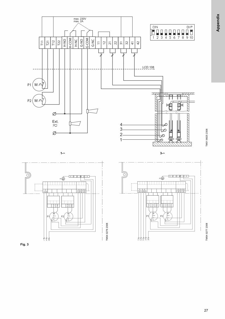
Ap
pe
nd
ix
1-~ 3-~
Fig. 3
TM
01
66
25
23
08
4
P1
P2
max. 230Vmax. 2A
T11
T21
T12
T22
H-N
O
H-C
OM
H-N
C
G-N
O
G-C
OM
G-N
C
11 12 21 22 31 32 41 42
TM
04
02
78
23
08
1N2
1U2
2N2
2U2
T22
T12
T21
T11
N1
U1
L
1 1P1 P2
TM
04
02
77
23
08
1W2
1V2
1U2
2V2
2U2
2W2
L3L2L1
T22
T12
T21
T11
N1
W1
V1
U1
P1 P2
27

Ap
pe
nd
ix
Fig. 4
TM
01
81
47
23
08
P1 P2
W1
V1
U1
1U2
N1
2U2
1V2
2V2
T11
T21
T12
T22
3U2
3V2
3W2
4U2
4V2
4W2
1W2
2W2
4321
max. 230Vmax. 2A
H-N
C
H-C
OM
H-N
O
G-NC
G-CO
MG-
NO
L1 L2 L3 N PE
PE
LCD 108
28

Ap
pe
nd
ix
1-~ 3-~
Fig. 5
TM
01
84
62
23
08
Ext.
34
21
P1
P2
LCD 108H
-NO
T22
T12
T21
T11
H-C
OM
H-N
C
G-N
O
G-C
OM
G-N
C
11 12 21 22 31 32 41 42
max. 230Vmax. 2A
ON DIP
1 2 3 4 5 6 7 8 9 10
TM
04
02
78
23
08
1N2
1U2
2N2
2U2
T22
T12
T21
T11
N1
U1
L
1 1P1 P2
TM
04
02
77
23
08
1W2
1V2
1U2
2V2
2U2
2W2
L3L2L1
T22
T12
T21
T11
N1
W1
V1
U1
P1 P2
29
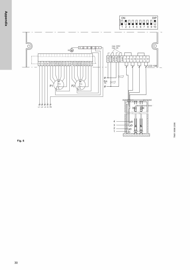
Ap
pe
nd
ix
Fig. 6
TM
01
85
98
23
08
W1
V1
U1
1U2
N1
2U2
1V2
2V2
T11
T21
T12
T22
3U2
3V2
3W2
4U2
4V2
4W2
1W2
2W2
P1 P2
L1 L2 L3 N PE
LCD 108
Ext.
4321
ON DIP
1 2 3 4 5 6 7 8 9 10
max. 230Vmax. 2A
H-N
O
H-C
OM
H-N
C
G-N
O
G-C
OM
G-N
C
11 12 21 22 31 32 41 42
30
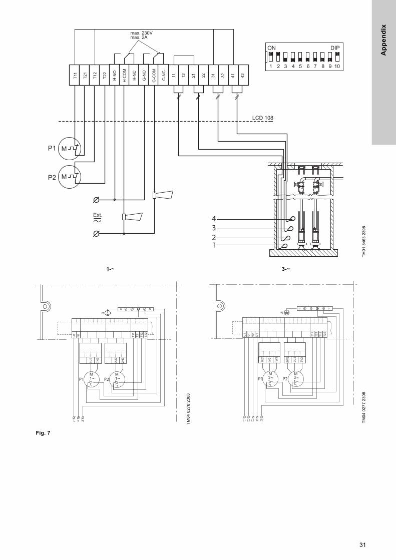
Ap
pe
nd
ix
1-~ 3-~
Fig. 7
TM
01
84
63
23
08
4321
P1
P2
H-N
O
T22
T12
T21
T11
H-C
OM
H-N
C
G-N
O
G-C
OM
G-N
C
11 12 21 22 31 32 41 42
LCD 108
Ext.
ON DIP
1 2 3 4 5 6 7 8 9 10
max. 230Vmax. 2A
TM
04
02
78
23
08
1N2
1U2
2N2
2U2
T22
T12
T21
T11
N1
U1
L
1 1P1 P2
TM
04
02
77
23
08
1W2
1V2
1U2
2V2
2U2
2W2
L3L2L1
T22
T12
T21
T11
N1
W1
V1
U1
P1 P2
31

Ap
pe
nd
ix
Fig. 8
TM
01
84
64
23
08
W1
V1
U1
1U2
N1
2U2
1V2
2V2
T11
T21
T12
T22
3U2
3V2
3W2
4U2
4V2
4W2
1W2
2W2
P1 P1
ON DIP
1 2 3 4 5 6 7 8 9 10
L1 L2 L3 N PE
LCD 108
4321
max. 230Vmax. 2A
H-N
C
H-C
OM
H-N
O
G-NC
G-CO
MG-
NO
32
De
cla
rati
on
of
co
nfo
rmit
y
33
Declaration of conformity 2
GB: EC declaration of conformityWe, Grundfos, declare under our sole responsibility that the products LC/LCD 107, LC/LCD 108, LC/LCD 109 and LC/LCD 110, to which this declaration relates, are in conformity with these Council directives on the approximation of the laws of the EC member states:
DE: EG-KonformitätserklärungWir, Grundfos, erklären in alleiniger Verantwortung, dass die Produkte LC/LCD 107, LC/LCD 108, LC/LCD 109 und LC/LCD 110, auf die sich diese Erklärung bezieht, mit den folgenden Richtlinien des Rates zur Angleichung der Rechtsvorschriften der EU-Mitgliedsstaaten übereinstimmen:
HU: EK megfelelőségi nyilatkozatMi, a Grundfos, egyedüli felelősséggel kijelentjük, hogy a LC/LCD 107, LC/LCD 108, LC/LCD 109 és LC/LCD 110 termékek, amelyekre jelen nyilatkozik vonatkozik, megfelelnek az Európai Unió tagállamainak jogi irányelveit összehangoló tanács alábbi előírásainak:
NL: EC overeenkomstigheidsverklaringWij, Grundfos, verklaren geheel onder eigen verantwoordelijkheid dat de producten LC/LCD 107, LC/LCD 108, LC/LCD 109 en LC/LCD 110 waarop deze verklaring betrekking heeft, in overeenstemming zijn met de Richtlijnen van de Raad in zake de onderlinge aanpassing van de wetgeving van de EG Lidstaten betreffende:
PL: Deklaracja zgodności WEMy, Grundfos, oświadczamy z pełną odpowiedzialnością, że nasze wyroby LC/LCD 107, LC/LCD 108, LC/LCD 109 oraz LC/LCD 110, których deklaracja niniejsza dotyczy, są zgodne z następującymi wytycznymi Rady d/s ujednolicenia przepisów prawnych krajów członkowskich WE:
RO: Declaraţie de conformitate CENoi, Grundfos, declarăm pe propria răspundere că produsele LC/LCD 107, LC/LCD 108, LC/LCD 109 şi LC/LCD 110, la care se referă această declaraţie, sunt în conformitate cu aceste Directive de Consiliu asupra armonizării legilor Statelor Membre CE:
— Machinery Directive (2006/42/EC).Standard used: EN 60204-1:2006.
— Low Voltage Directive (2006/95/EC).Standard used: EN 60439-1:2004.
— EMC Directive (2004/108/EC).Standards used: EN 61000-6-2:2005 and EN 61000-6-3:2007.
This EC declaration of conformity is only valid when published as part of the Grundfos installation and operating instructions (publication number 96843435 0115).
Bjerringbro, 15th June 2010
Jan StrandgaardTechnical Director
Grundfos Holding A/SPoul Due Jensens Vej 7
8850 Bjerringbro, Denmark
Person authorised to compile technical file andempowered to sign the EC declaration of conformity.

34

Gru
nd
fos
co
mp
anie
s
ArgentinaBombas GRUNDFOS de Argentina S.A.Ruta Panamericana km. 37.500 Centro Industrial Garin1619 Garín Pcia. de B.A.Phone: +54-3327 414 444Telefax: +54-3327 45 3190
AustraliaGRUNDFOS Pumps Pty. Ltd. P.O. Box 2040 Regency Park South Australia 5942 Phone: +61-8-8461-4611 Telefax: +61-8-8340 0155
AustriaGRUNDFOS Pumpen Vertrieb Ges.m.b.H.Grundfosstraße 2 A-5082 Grödig/Salzburg Tel.: +43-6246-883-0 Telefax: +43-6246-883-30
BelgiumN.V. GRUNDFOS Bellux S.A. Boomsesteenweg 81-83 B-2630 Aartselaar Tél.: +32-3-870 7300 Télécopie: +32-3-870 7301
BelarusПредставительство ГРУНДФОС в Минске220125, Минскул. Шафарнянская, 11, оф. 56, БЦ «Порт»Тел.: +7 (375 17) 286 39 72/73Факс: +7 (375 17) 286 39 71E-mail: [email protected]
Bosnia and HerzegovinaGRUNDFOS SarajevoZmaja od Bosne 7-7A,BH-71000 SarajevoPhone: +387 33 592 480Telefax: +387 33 590 465www.ba.grundfos.come-mail: [email protected]
BrazilBOMBAS GRUNDFOS DO BRASILAv. Humberto de Alencar Castelo Branco, 630CEP 09850 - 300São Bernardo do Campo - SPPhone: +55-11 4393 5533Telefax: +55-11 4343 5015
BulgariaGrundfos Bulgaria EOODSlatina DistrictIztochna Tangenta street no. 100BG - 1592 SofiaTel. +359 2 49 22 200Fax. +359 2 49 22 201email: [email protected]
CanadaGRUNDFOS Canada Inc. 2941 Brighton Road Oakville, Ontario L6H 6C9 Phone: +1-905 829 9533 Telefax: +1-905 829 9512
ChinaGRUNDFOS Pumps (Shanghai) Co. Ltd.10F The Hub, No. 33 Suhong RoadMinhang DistrictShanghai 201106PRCPhone: +86 21 612 252 22Telefax: +86 21 612 253 33
COLOMBIAGRUNDFOS Colombia S.A.S.Km 1.5 vía Siberia-Cota Conj. Potrero Chico,Parque Empresarial Arcos de Cota Bod. 1A.Cota, CundinamarcaPhone: +57(1)-2913444Telefax: +57(1)-8764586
CroatiaGRUNDFOS CROATIA d.o.o.Buzinski prilaz 38, BuzinHR-10010 ZagrebPhone: +385 1 6595 400 Telefax: +385 1 6595 499www.hr.grundfos.com
GRUNDFOS Sales Czechia and Slovakia s.r.o.Čajkovského 21779 00 OlomoucPhone: +420-585-716 111
DenmarkGRUNDFOS DK A/S Martin Bachs Vej 3 DK-8850 Bjerringbro Tlf.: +45-87 50 50 50 Telefax: +45-87 50 51 51 E-mail: [email protected]/DK
EstoniaGRUNDFOS Pumps Eesti OÜPeterburi tee 92G11415 TallinnTel: + 372 606 1690Fax: + 372 606 1691
FinlandOY GRUNDFOS Pumput AB Trukkikuja 1 FI-01360 Vantaa Phone: +358-(0) 207 889 500
FrancePompes GRUNDFOS Distribution S.A. Parc d’Activités de Chesnes 57, rue de Malacombe F-38290 St. Quentin Fallavier (Lyon) Tél.: +33-4 74 82 15 15 Télécopie: +33-4 74 94 10 51
GermanyGRUNDFOS GMBHSchlüterstr. 3340699 ErkrathTel.: +49-(0) 211 929 69-0 Telefax: +49-(0) 211 929 69-3799e-mail: [email protected] in Deutschland:e-mail: [email protected]
GreeceGRUNDFOS Hellas A.E.B.E. 20th km. Athinon-Markopoulou Av. P.O. Box 71 GR-19002 Peania Phone: +0030-210-66 83 400 Telefax: +0030-210-66 46 273
Hong KongGRUNDFOS Pumps (Hong Kong) Ltd. Unit 1, Ground floor Siu Wai Industrial Centre 29-33 Wing Hong Street & 68 King Lam Street, Cheung Sha Wan Kowloon Phone: +852-27861706 / 27861741 Telefax: +852-27858664
HungaryGRUNDFOS Hungária Kft.Park u. 8H-2045 Törökbálint, Phone: +36-23 511 110Telefax: +36-23 511 111
IndiaGRUNDFOS Pumps India Private Limited118 Old Mahabalipuram RoadThoraipakkamChennai 600 096Phone: +91-44 2496 6800
IndonesiaPT. GRUNDFOS POMPAGraha Intirub Lt. 2 & 3Jln. Cililitan Besar No.454. Makasar, Jakarta TimurID-Jakarta 13650Phone: +62 21-469-51900Telefax: +62 21-460 6910 / 460 6901
IrelandGRUNDFOS (Ireland) Ltd. Unit A, Merrywell Business ParkBallymount Road LowerDublin 12 Phone: +353-1-4089 800 Telefax: +353-1-4089 830
ItalyGRUNDFOS Pompe Italia S.r.l. Via Gran Sasso 4I-20060 Truccazzano (Milano)Tel.: +39-02-95838112 Telefax: +39-02-95309290 / 95838461
JapanGRUNDFOS Pumps K.K.1-2-3, Shin-Miyakoda, Kita-ku, Hamamatsu431-2103 JapanPhone: +81 53 428 4760Telefax: +81 53 428 5005
KoreaGRUNDFOS Pumps Korea Ltd.6th Floor, Aju Building 679-5Yeoksam-dong, Kangnam-ku, 135-916Seoul, KoreaPhone: +82-2-5317 600Telefax: +82-2-5633 725
LatviaSIA GRUNDFOS Pumps Latvia Deglava biznesa centrsAugusta Deglava ielā 60, LV-1035, Rīga,Tālr.: + 371 714 9640, 7 149 641Fakss: + 371 914 9646
LithuaniaGRUNDFOS Pumps UABSmolensko g. 6LT-03201 VilniusTel: + 370 52 395 430Fax: + 370 52 395 431
MalaysiaGRUNDFOS Pumps Sdn. Bhd.7 Jalan Peguam U1/25Glenmarie Industrial Park40150 Shah AlamSelangor Phone: +60-3-5569 2922Telefax: +60-3-5569 2866
MexicoBombas GRUNDFOS de México S.A. de C.V. Boulevard TLC No. 15Parque Industrial Stiva AeropuertoApodaca, N.L. 66600Phone: +52-81-8144 4000 Telefax: +52-81-8144 4010
NetherlandsGRUNDFOS NetherlandsVeluwezoom 351326 AE AlmerePostbus 220151302 CA ALMERE Tel.: +31-88-478 6336 Telefax: +31-88-478 6332E-mail: [email protected]
New ZealandGRUNDFOS Pumps NZ Ltd.17 Beatrice Tinsley CrescentNorth Harbour Industrial EstateAlbany, AucklandPhone: +64-9-415 3240Telefax: +64-9-415 3250
NorwayGRUNDFOS Pumper A/S Strømsveien 344 Postboks 235, Leirdal N-1011 Oslo Tlf.: +47-22 90 47 00 Telefax: +47-22 32 21 50
PolandGRUNDFOS Pompy Sp. z o.o.ul. Klonowa 23Baranowo k. PoznaniaPL-62-081 PrzeźmierowoTel: (+48-61) 650 13 00Fax: (+48-61) 650 13 50
PortugalBombas GRUNDFOS Portugal, S.A. Rua Calvet de Magalhães, 241Apartado 1079P-2770-153 Paço de ArcosTel.: +351-21-440 76 00Telefax: +351-21-440 76 90
RomaniaGRUNDFOS Pompe România SRLBd. Biruintei, nr 103 Pantelimon county IlfovPhone: +40 21 200 4100Telefax: +40 21 200 4101E-mail: [email protected]
RussiaООО Грундфос Россия109544, г. Москва, ул. Школьная, 39-41, стр. 1Тел. (+7) 495 564-88-00 (495) 737-30-00Факс (+7) 495 564 88 11E-mail [email protected]
Serbia Grundfos Srbija d.o.o.Omladinskih brigada 90b11070 Novi Beograd Phone: +381 11 2258 740Telefax: +381 11 2281 769www.rs.grundfos.com
SingaporeGRUNDFOS (Singapore) Pte. Ltd.25 Jalan Tukang Singapore 619264 Phone: +65-6681 9688 Telefax: +65-6681 9689
SlovakiaGRUNDFOS s.r.o.Prievozská 4D 821 09 BRATISLAVA Phona: +421 2 5020 1426sk.grundfos.com
SloveniaGRUNDFOS LJUBLJANA, d.o.o.Leskoškova 9e, 1122 LjubljanaPhone: +386 (0) 1 568 06 10Telefax: +386 (0)1 568 06 19E-mail: [email protected]
South AfricaGRUNDFOS (PTY) LTDCorner Mountjoy and George Allen RoadsWilbart Ext. 2Bedfordview 2008Phone: (+27) 11 579 4800Fax: (+27) 11 455 6066E-mail: [email protected]
SpainBombas GRUNDFOS España S.A. Camino de la Fuentecilla, s/n E-28110 Algete (Madrid) Tel.: +34-91-848 8800 Telefax: +34-91-628 0465
SwedenGRUNDFOS AB Box 333 (Lunnagårdsgatan 6) 431 24 Mölndal Tel.: +46 31 332 23 000Telefax: +46 31 331 94 60
SwitzerlandGRUNDFOS Pumpen AG Bruggacherstrasse 10 CH-8117 Fällanden/ZH Tel.: +41-44-806 8111 Telefax: +41-44-806 8115
TaiwanGRUNDFOS Pumps (Taiwan) Ltd. 7 Floor, 219 Min-Chuan Road Taichung, Taiwan, R.O.C. Phone: +886-4-2305 0868Telefax: +886-4-2305 0878
ThailandGRUNDFOS (Thailand) Ltd. 92 Chaloem Phrakiat Rama 9 Road,Dokmai, Pravej, Bangkok 10250Phone: +66-2-725 8999Telefax: +66-2-725 8998
TurkeyGRUNDFOS POMPA San. ve Tic. Ltd. Sti.Gebze Organize Sanayi Bölgesi Ihsan dede Caddesi,2. yol 200. Sokak No. 20441490 Gebze/ KocaeliPhone: +90 - 262-679 7979Telefax: +90 - 262-679 7905E-mail: [email protected]
UkraineБізнес Центр ЄвропаСтоличне шосе, 103м. Київ, 03131, Україна Телефон: (+38 044) 237 04 00 Факс.: (+38 044) 237 04 01E-mail: [email protected]
United Arab EmiratesGRUNDFOS Gulf DistributionP.O. Box 16768Jebel Ali Free ZoneDubaiPhone: +971 4 8815 166Telefax: +971 4 8815 136
United KingdomGRUNDFOS Pumps Ltd. Grovebury Road Leighton Buzzard/Beds. LU7 4TL Phone: +44-1525-850000 Telefax: +44-1525-850011
U.S.A.GRUNDFOS Pumps Corporation 17100 West 118th TerraceOlathe, Kansas 66061Phone: +1-913-227-3400 Telefax: +1-913-227-3500
UzbekistanGrundfos Tashkent, Uzbekistan The Repre-sentative Office of Grundfos Kazakhstan in Uzbekistan38a, Oybek street, TashkentТелефон: (+998) 71 150 3290 / 71 150 3291Факс: (+998) 71 150 3292
Addresses Revised 05.12.2016

96843435 0115
ECM: 1149289 The
nam
e G
rund
fos,
the
Gru
ndfo
s lo
go, a
nd b
e t
hin
k i
nn
ov
ate
are
regi
ster
ed tr
adem
arks
ow
ned
by G
rund
fos
Hol
ding
A/S
or G
rund
fos
A/S,
Den
mar
k. A
ll rig
hts
rese
rved
wor
ldw
ide.
© C
opyr
ight
Gru
ndfo
s H
oldi
ng A
/S
www.grundfos.com