Installation and Operating Instructions - Fire Alarm...
52
4005 Fire Alarm Installation and Operating Instructions 574-068 Rev. C Technical Manuals Online! - http://www.tech-man.com
Transcript of Installation and Operating Instructions - Fire Alarm...

4005 Fire Alarm
Installation and OperatingInstructions
574-068 Rev. C
Technical Manuals Online! - http://www.tech-man.com

Technical Manuals Online! - http://www.tech-man.com

The information in this document is subject to change without notice. No part of this document may be reproduced or transmitted in any form or by any means, electronic or mechanical, for any purpose, without prior written consent of Simplex Time Recorder Company.
Copyright 2000 by Simplex Time Recorder Company Simplex Plaza Westminster, MA 01441-0001 All Rights Reserved Printed in the United States of America Walk Test is protected by U.S. Patent No. 4,725,818. All other logos and product names are trademarks or registered trademarks of their respective companies.
DO NOT INSTALL ANY SIMPLEX PRODUCT THAT APPEARS DAMAGED. Upon unpacking your Simplex product, inspect the contents of the carton for shipping damage. If damage is apparent, immediately file a claim with the carrier and notify Simplex.
ELECTRICAL HAZARD - Disconnect electrical power when making any internal adjustments or repairs. Servicing should be performed by qualified Simplex Representatives. STATIC HAZARD - Static electricity can damage components. Therefore, handle as follows: 1. Ground yourself before opening or installing components (use the
553-484 Static Control Kit). 2. Keep uninstalled component wrapped in anti-static material at all
times.
RADIO FREQUENCY ENERGY - This equipment generates, uses, and can radiate radio frequency energy and if not installed and used in accordance with the instruction manual, may cause interference to radio communications. It has been tested and found to comply with the limits for a Class A computing device pursuant to Subpart J of Part 15 of FCC Rules, which are designed to provide reasonable protection against such interference when operated in a commercial environment. Operation of this equipment in a residential area may cause interference in which case the user at his own expense will be required to take whatever measures may be required to correct the interference.
NOTICE
Copyright and Trademarks
Cautions and Warnings
Technical Manuals Online! - http://www.tech-man.com

Technical Manuals Online! - http://www.tech-man.com

i
Chapter 1 System Overview ...............................................................1-1 Introduction .........................................................................................1-1 In this Chapter.....................................................................................1-1 Product and Part Numbers .................................................................1-2 Description ..........................................................................................1-2 Features..............................................................................................1-4 Specifications......................................................................................1-5 System Modules .................................................................................1-6
Base Panel Modules .......................................................................1-6 CPU Board...................................................................................1-6 Power Supply / Charger...............................................................1-7 Power Distribution Board .............................................................1-7 4-Point IDC Card (low current) ....................................................1-8 4-Point NAC/Relay Card..............................................................1-8
Optional Modules ............................................................................1-9 2 IDC and 2 NAC/Relay Card ......................................................1-9 Class A Adapter Card..................................................................1-9 8-Point I/O Card...........................................................................1-9 Expansion Power Supply.............................................................1-9 City Circuit Card...........................................................................1-9 DACT Card ..................................................................................1-9
Chapter 2 Installation..........................................................................2-1
Overview .............................................................................................2-1 In this Chapter.....................................................................................2-1 Important Notes ..................................................................................2-1 Tools and Equipment..........................................................................2-2 Back Box Installation...........................................................................2-2
Chapter 3 System Operation ..............................................................3-1
Overview .............................................................................................3-1 In this Chapter.....................................................................................3-1 Operator Interface (Front Panel).........................................................3-2 System Initialization (Power-Up) .........................................................3-3 Operation ............................................................................................3-4
Operating Description .....................................................................3-4 Operator Key Definitions .................................................................3-5 Menu Navigation Key descriptions ..................................................3-6
Handling Abnormal Conditions ...........................................................3-8 Acknowledging an Alarm, Trouble, or Supervisory Condition .........3-8 How to Silence Alarms ....................................................................3-9 How to Reset the System................................................................3-9 How to Warm Start the System.....................................................3-10
Passcodes and Access Levels .........................................................3-11 Menu Structure..............................................................................3-11 Login/Logout (Passcodes & Access levels) ..................................3-11 Logging In/Out...............................................................................3-12
Continued on next Page
Table of Contents
Technical Manuals Online! - http://www.tech-man.com

ii
Chapter 3 System Operation (continued) Logs ..................................................................................................3-13
Historical Logs...............................................................................3-13 Viewing Logs .................................................................................3-13 Clearing Logs ................................................................................3-14 Log Messages...............................................................................3-14
Walk Test.......................................................................................3-16 Control / View Points.........................................................................3-17
View a Point or List........................................................................3-17 Edit a Custom Label......................................................................3-18 Custom Point Label Characters ....................................................3-19 Disabling an Active Point...............................................................3-19 Disable/Enable a Point ..................................................................3-20
Function Menu ..................................................................................3-21 Function menu Options .................................................................3-21 Manual Evacuation........................................................................3-21 City Circuit Disconnect ..................................................................3-22 Control Point Bypass.....................................................................3-22 Elevator Bypass ............................................................................3-23 Doorholder Bypass........................................................................3-23 Lamp Test .....................................................................................3-24
APPENDIX A........................................................................Appendix A-1
Glossary of Terms ............................................................. Appendix A-1 APPENDIX B........................................................................Appendix B-1
Regulatory Information....................................................... Appendix B-1 NPFA Standards ............................................................ Appendix B-1 Factory Mutual Approved ............................................... Appendix B-1 Local Approvals.............................................................. Appendix B-1 Installation Requirements............................................... Appendix B-2
Codes and Standards................................................. Appendix B-2 APPENDIX C........................................................................Appendix C-1
Single-Sheet Operating Instructions ..............................Appendix C-1
Table of Contents, Continued
Technical Manuals Online! - http://www.tech-man.com
1-1
This publication describes how to install, configure, operate, program and test the Simplex 4005 Fire Alarm. Refer to the publications listed below for more information.
Publication Title Part # 4005 Fire Alarm – Programming Instructions . . . Rev. A
574-059
4005 Operating Instructions Following an Alarm/Supervisory/Trouble Condition . . . Ed 8 95
574-069
4005 Fire Alarm I/O Cards – Installation Instructions . . . Ed 3 96
574-070
4005 Fire Alarm City Circuit Card – Installation Instructions . . . Rev. B
574-071
4005 Fire Alarm Expansion Power Supply & Power Distribution Boards – Installation Instructions . . . Rev. A
574-072
4005 Fire Alarm Adapter Kit — Installation Instructions . . . Rev. B
574-080
4005 Fire Alarm Rev. 1.02 — Release Note . . . Rev. A
574-083
4005 Field Wiring Diagram 841-990
This chapter discusses the following topics:
Topic See Page # Introduction 1-1 Product and Part Numbers 1-2 Product Description 1-2 Product Features 1-4 Specifications 1-5 Base Panel Modules 1-6 Optional Modules 1-9
Location of Tables and Diagrams in this chapter:
Tables and Diagrams See Page # Table 1-1. 4005 Base Panel Product and Part
Numbers
1-2
Table 1-2. 4005 Optional Module Product and Part Numbers
1-2
Figure 1-1. 4005 Base Panel Card layout 1-3
Chapter 1 System Overview
Introduction
Related Documents
In this Chapter
Technical Manuals Online! - http://www.tech-man.com

1-2
Tables 1-1 and 1-2 describe Base Panel and Optional components of the 4005 with their associated Product (PID) numbers and Part numbers.
Table 1-1. 4005 Base Panel Product and Part Numbers
Description Product No. Part No.
4005 Base Panel (beige) 4005-9101
566-151 (CPU)
4005 Base Panel (red) 4005-9102 566-252 (Pwr Supply)
4-Circuit IDC Card (low-current) 4005-9804 565-473 4-Point NAC/Relay Card 4005-9805 565-477 Five Slot Power Distribution Module 4005-9807 565-471
Table 1-2. 4005 Optional Module Product and Part Numbers
Description Product No. Part No.
2-IDC/2-NAC/Relay Card 4005-9803 565-552 Class A Adapter Card 4005-9806 565-556 8-Point I/O Card 4005-9808 565-554 City Circuit Card 4005-9809 565-550 DACT Card 4005-9810 565-626 Expansion Power Supply 4005-9813 565-481 4-Circuit IDC Card (high-current, Class B) 4005-9824 565-610
The 4005 is a microprocessor-based, battery-backed, electrically-supervised fire alarm system capable of supporting from 8 to 40 circuits. These circuits, either initiating device circuits (IDC) or notification appliance circuits (NAC), are added to the system in blocks of four. In addition, the 4005 can automatically control supplementary equipment such as fire doors and fans during a fire condition using NACs converted to auxiliary relay outputs.
The 4005 provides audible and visible indications during trouble, supervisory, or alarm (fire) conditions. Should any of these conditions occur, the system activates the applicable notification appliance(s), LEDs, and the panel tone-alert. The indications continue until someone appropriately acknowledges the condition.
Figure 1-1 illustrates the physical layout of the cards and wiring areas within the base 4005 panel. The I/O cards plug into slots of the Power Distribution Card(s) along either side of the CPU. A maximum of 10 slots are available. The non-power-limited wiring area is shaded.
Continued on next page
Description and Features
Product and Part Numbers
Description
Technical Manuals Online! - http://www.tech-man.com

1-3
CITY1/DACT CITY2TP3
TP1
TP2
P5P6
P4
K1
U33
R95 WARM START
EXT RUI DET PWRINT RUI
RS-232 PORT
1234
ASSY 0565-473 4 POINT IDC
TB1
**SYSTEM IS NORMAL** 12:02:15PM AUG 10, 1995
ALARMACK
SUPVACK
TROUBLEACK
ALARMSILENCE
SYSTEMRESET
FIREALARM
SYSTEMSUPERVISORY
SYSTEMTROUBLE
ALARMSILENCED
ACPOWER
P2
P1
SW2
R83TB1 TB2
AC Line AC Ret Earth
115V
NEG POS
P3
T1
F1 3A
JW1
R69
SW1
ASSY 0565-473 4 POINT IDC
TB1
NAC/RELAY ASSY565-477
TB1J1F1
F2
F3
F4
3A
3A
3A
3A
K1
K2
K3
K4
Optional I/O Card
Optional I/O Card
Optional I/O Card
Optional I/O Card
Optional I/O Card
Optional City/DACT Optional City Card 2
Card 1
Battery (18Ah Max.) Battery (18Ah Max.)
Optional I/O Card
Optional I/O Card
Figure 1-1. 4005 Base Panel Card layout
Continued on next page
Description and Features, Continued
Description (continued)
Non-Power-Limited Wiring
Optional Expansion Power Supply (Behind I/O Cards)
Power Supply (Behind I/O Cards)
Technical Manuals Online! - http://www.tech-man.com

1-4
The 4005 has the following features:
• General Alarm or Selective Signaling • 2-Line X 40-Character Supertwist LCD display • Menu-Driven Prompts • 8 (to a maximum of 36) Initiating Device Circuits (IDCs) • 4 (to a maximum of 32) Relay/Notification Appliance Circuits (NACs) • Power Supplies • Power to meet Americans with Disabilities Act (ADA) Requirements • Built-in Serial Annunciator Driver • Surface or Semi-Flush Installation • Pluggable Terminals Blocks • Single-Piece Chassis • ONLINE Programming • Non-Volatile Program Memory • 3 Levels of Battery Supervision: Low Battery, Depleted Battery, and
Missing Battery • Active Status Reminder • Circuit Disable/Enable • Abort Enable Feature • Manual Circuit Control • Chronological Event History Logs • One-Person Walk Test • Indicator (Lamp) Test • Passcode Protected Function Key • Available with Optional:
− Internal Digital Alarm Communication Transmitter (DACT) − Supervised I/O Modules (programmable) − City Circuits − Class A (Style D / Style Z) Adapters − Full-Function Remote Annunciator Interface − Simplex 4003 Voice Control Panel (VCP) and 4009 NAC Power
Extender Compatibility
Description and Features, Continued
Features
Technical Manuals Online! - http://www.tech-man.com

1-5
110 VAC: 3A @ 120 VAC, 60 Hz 240 VAC: 1.5A @ 220/240 VAC, 50/60 Hz
24 VDC, 6.2Ah to 33Ah CAUTION: The 4005 must be grounded properly. Readings of less than
0.70 VAC must be measured between ground and neutral. A system ground must be provided for Earth Detection and transient protection devices. This connection shall be made to an approved, dedicated Earth connection per NFPA 70, article 250, and NFPA 78. Connect a 12 AWG copper ground wire from safety ground (electrical distribution panel) to the 4005 grounding terminal on the AC terminal block.
Specifications
Input Power
Battery Backup
Technical Manuals Online! - http://www.tech-man.com

1-6
The 4005 base panel consists of:
• Fire Alarm CPU Board • 4 Amp Power Supply/Charger. • Two 4-point IDC Cards (low-current) with 8 points configured as Point
Type FIRE • One 4-point NAC/Relay Card with 4 points configured as NACs, Point
Type SSIGNAL. • A capacity to hold up to ten I/O cards (10 Slots).
The base 4005 panel comes completely assembled and ready to install in the back box. Refer to Figure 1-1 (page1-3) and the Module and Wiring Identification Chart on the inside of the panel door for the locations of each card. Refer to Table 1-1 (page 1-2) for Product (PID) and Part numbers. For more information on the following modules, refer to each of their individual installation instructions:
• I/O Cards (Publication No. 574-070) • City Circuit Card (Publication No. 574-071) • Power Distribution Card (Publication No. 574-072)
The 4005 CPU board controls the system’s functions. The CPU is responsible for all alarm and supervisory actions as well as the control of the front panel display which provides the operator interface.
The 4005 CPU board contains:
• Main microprocessor and system memory • Tone alert • LCD • Control panel with operator key inputs • LED indicators • Internal system connectors • Field wiring terminal block for RUI and 4-wire detector power connectors
Continued on next page
Base Panel Modules
Overview
CPU Board
Technical Manuals Online! - http://www.tech-man.com
1-7
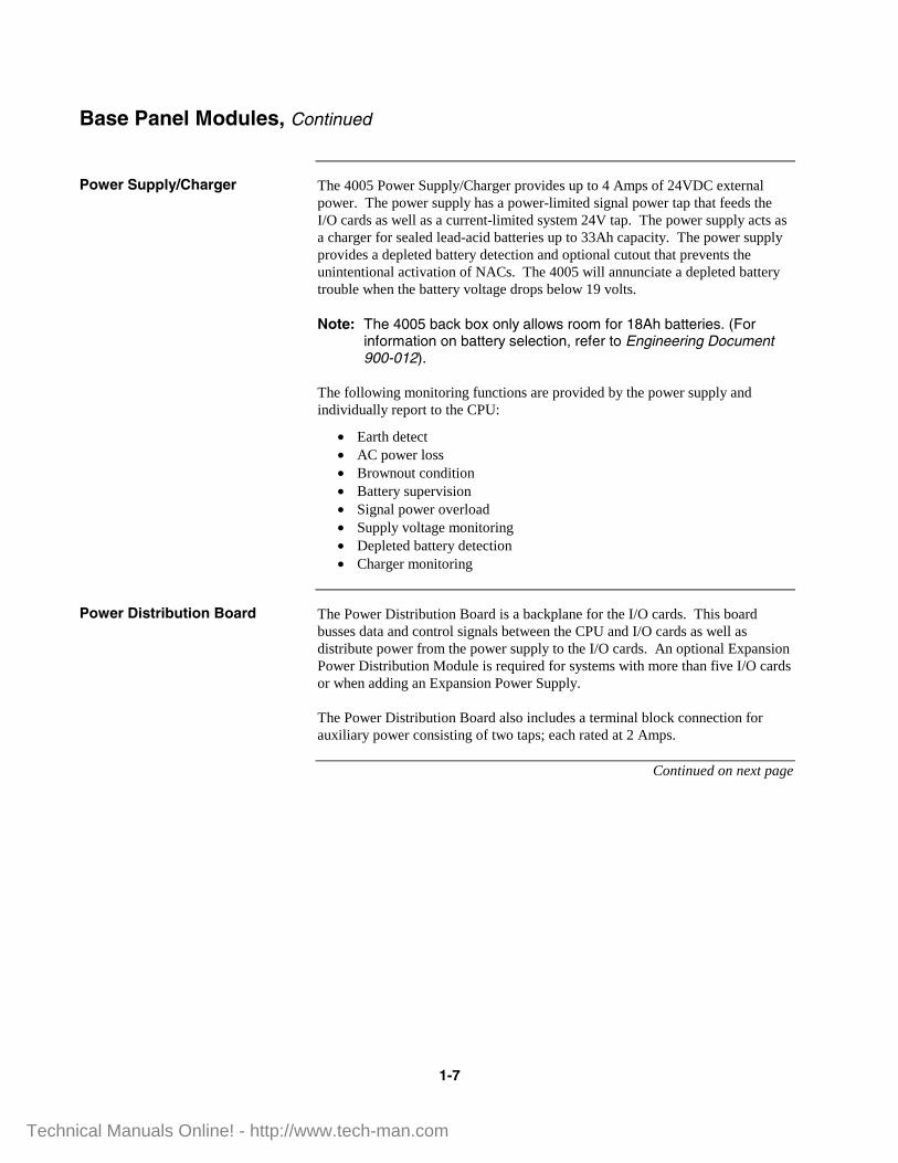
The 4005 Power Supply/Charger provides up to 4 Amps of 24VDC external power. The power supply has a power-limited signal power tap that feeds the I/O cards as well as a current-limited system 24V tap. The power supply acts as a charger for sealed lead-acid batteries up to 33Ah capacity. The power supply provides a depleted battery detection and optional cutout that prevents the unintentional activation of NACs. The 4005 will annunciate a depleted battery trouble when the battery voltage drops below 19 volts. Note: The 4005 back box only allows room for 18Ah batteries. (For
information on battery selection, refer to Engineering Document 900-012).
The following monitoring functions are provided by the power supply and individually report to the CPU:
• Earth detect • AC power loss • Brownout condition • Battery supervision • Signal power overload • Supply voltage monitoring • Depleted battery detection • Charger monitoring
The Power Distribution Board is a backplane for the I/O cards. This board busses data and control signals between the CPU and I/O cards as well as distribute power from the power supply to the I/O cards. An optional Expansion Power Distribution Module is required for systems with more than five I/O cards or when adding an Expansion Power Supply.
The Power Distribution Board also includes a terminal block connection for auxiliary power consisting of two taps; each rated at 2 Amps.
Continued on next page
Base Panel Modules, Continued
Power Supply/Charger
Power Distribution Board
Technical Manuals Online! - http://www.tech-man.com

1-8
The 4-Point IDC card provides four Style B (Class B) monitor zones. Each circuit supports a Disable/Enable capability which can be controlled from the front panel. Note: This low-current card does not support 2-wire detectors with
relays. An optional 4-Point IDC Card (high-current) card (Part No. 565-610) does support 2-wire detectors with relays.
The 4-Point NAC/Relay card provides 4 field-configurable output points. The field wiring connects to an 8-position terminal block. You can configure these points as either NAC or Auxiliary relay by moving the relay to a different socket position on the board.
Base Panel Modules, Continued
4-Point IDC Card (low-current)
4-Point NAC/Relay Card
Technical Manuals Online! - http://www.tech-man.com

1-9
The 4005 has several optional modules which are installed in the positions indicated in Figure 1-1 (page 1-3). Refer to Table 1-2 (page 1-2) for Product (PID) and Part numbers. For more information on the following modules, refer to each of their individual installation instructions:
• 2 IDC and 2 NAC/Relay Card (Publication No. 574-070) • Class A Adapter Card (Publication No. 574-070) • 8-Point I/O Card (Publication No. 574-070) • Expansion Power Supply (Publication No. 574-072) • City Circuit Card (Publication No. 574-071) • DACT Card (Publication No. 574-049)
This card combines 2 IDCs and 2 Outputs (jumper configurable as NACs or relays). The default configuration for this card is 2 IDCs (low-current) with point type FIRE (Generic Fire Zone) and 2 NACs with point type SSIGNAL (ON ’til Silence).
Note: A high-current IDC version of this card is not available.
This board mounts onto any of the IDC or NAC/Relay cards for conversion of their IDC and NAC points to Style D or Z (Class A).
Note: This card is jumper configurable to support low-current IDCs and NACs. Use separate EOL resistors at the terminal block of the adapter card for high-current IDCs. (refer to Field Wiring Diagram 841-990)
This card fits into a single I/O card slot and provides eight points. Each point is configurable for supervised input or output functionality.
The Expansion Power Supply adds 5 amps of external power to the 4005 and mounts on the left side of the box behind I/O Cards 6-10. This power supply does not produce 5V power and does not provide any battery charging functions. It provides its power to the expansion power distribution module only.
Note: An Expansion Power Distribution Module is required when using the Expansion Power Supply.
Up to two City Circuit Cards are available for a 4005. The city circuit cards mount onto the expansion plug on the CPU board. The card provides a jumper-selectable city connection that can be configured as Local Energy, Reverse Polarity, or Form “C” contacts.
Note: The 4005 will accept either the City Circuit Cards or the DACT card option, but not both.
This card mounts directly below the CPU board and connects to the CPU board expansion plug. The 4005’s internal DACT card is capable of communicating Alarm, Supervisory, Trouble, and AC Power Fail conditions to a receiver in a Remote Supervising Station or Central Station System.
Optional Modules
Overview
2 IDC & 2 NAC/Relay Card
Class A Adapter Card
8-Point I/O Card
Expansion Power Supply
City Circuit Card
DACT Card
Technical Manuals Online! - http://www.tech-man.com

Technical Manuals Online! - http://www.tech-man.com

2-1
This chapter describes how to install, wire, and perform a system checkout of the 4005 Fire Alarm.
This chapter discusses the following topics:
Topic See Page # Overview 2-1 Important Notes 2-1 Installation 2-2 Tools and Equipment 2-2 Back Box Installation 2-2
Location of Tables and Diagrams in this chapter:
Tables and Diagrams See Page # Figure 2-1. Back Box Installation 2-2
• Notify appropriate personnel (building occupants, fire department, and/or monitoring facility, etc.) of the installation.
• Ensure that you are thoroughly familiar with these instructions and all regulatory information (see Appendix B) before installing the 4005 Fire Alarm system.
Chapter 2 Installation
Overview
In this Chapter
Important Notes
Technical Manuals Online! - http://www.tech-man.com

2-2
The following tools and equipment are required for 4005 installation:
• 1/4-inch flat-tip Screwdriver • Volt-Ohmmeter • Diagonal Cutting Pliers • Wire Strippers • 841-990 Field Wiring Diagram
The installer is responsible for safeguarding all 4005 material shipped to the job site. During system installation, store all 4005 items (including all documentation) in a clean, dry, and safe place until needed.
1. Remove the back box from the shipping container and lay the back box on a flat surface.
2. Using the information in Figure 2-1 (below) for reference, install the back box.
• For specific internal wiring directions, refer to Figure 2-1, the back box installation label inside the back box, and to Field Wiring
Diagram #841-990.
Measurement Box Door Weight (SEE NOTE 6) 11.5 lb [ 25.3 kg] 7.5 lb [ 16.5 kg] Height 23-1/8 in [58.7 cm] 24 in [61.0 cm] Width 22-1/2 in [57.2 cm] 23-1/2 in [59.7 cm] Rough Opening (SEE NOTE 2)
23-1/8 in [58.7 cm]
22-1/2 in [57.2 cm]
SEENOTE 1 USE 4 HOLES TO
SECURE BACK BOXTO THE WALL
TOP
SEENOTES
SEE NOTES
SEE NOTES
BBB
A AA
2 & 3
SEENOTE 7
4 & 5
4 & 5
CAUTION: ENCLOSURE MUST BE LEVEL AND PLUMB WHEN INSTALLED.
DOOR
1/2-INCHWALL BOARD 2X4 WALL
STUD
NAILKNOCKOUT
Figure 2-1. Back Box Installation
Installation
Tools and Equipment
Back Box Installation
NOTES: 1. BOX CAN BE MOUNTED SEMI-FLUSH WITH THE SURFACE OF THE WALL.
2. DIMENSIONS SHOWN ARE TYPICAL FOR ALL SURFACE AND SEMI-FLUSH INSTALLATIONS.
3. USE ROUGH OPENING DIMENSIONS WHEN PREPARING SEMI-FLUSH INSTALLATIONS.
4. "A" CONDUIT DENOTES ONLY NON-POWER LIMITED WIRING.
"B" CONDUIT DENOTES ONLY POWER-LIMITED WIRING.
3/4-INCH KNOCKOUTS ARE PROVIDED.
5. WHEN PROVIDING ADDITIONAL CONDUIT ENTRANCES TO THE BOX, USE A SUITABLE PUNCH TO PROVIDE SEPARATE CONDUIT ENTRANCES FOR POWER- LIMTED AND NON-POWER LIMITED WIRING (AC POWER, BATTERY, CITY CONNECT) AT OPPOSITE ENDS OF BOX, CHECK SYSTEM LABEL ON DOOR FOR POWER-LIMITED INFORMATION.
6. WEIGHT IS IN POUNDS, AND DOES NOT INCLUDE THE BATTERIES.
7. THIS SPACE MUST BE KEPT FREE OF WIRING FOR BATTERY INSTALLATION.
Technical Manuals Online! - http://www.tech-man.com

3-1
The operator interface with the system consists of control keys, LEDs, a 2-line by 40-character backlit LCD (see Figure 3-1 for the positions of each), and a tone-alert which are mounted in the control panel. The purposes of the controls and indicators are listed in the Operation section of this chapter (page 3-4).
This chapter discusses the following topics:
Topic See Page # Overview 3-1 System Initialization 3-3 Operation 3-4 Handling Abnormal Conditions 3-8 Passcodes and Access levels 3-11 Logs 3-13 Walk Test 3-16 Control / View Points 3-17 Function Menu 3-21
Location of Tables and Diagrams in this chapter:
Tables and Diagrams See Page # Figure 3-1. Operator Interface (Control Panel) 3-2 Figure 3-2. Trouble Display 3-3 Figure 3-3. Abnormal Condition Display 3-8 Figure 3-4. Menu Structure (Access level 1) 3-11 Figure 3-5. Viewing History Log 3-13 Figure 3-6. Clearing a Log 3-14 Figure 3-7. Log Display format 3-14 Figure 3-8. Log Display 3-14 Figure 3-9. Secondary Log Display Format 3-15 Figure 3-10. Secondary Log Display 3-15 Figure 3-11. Walk Test Intital Display 3-16 Figure 3-12. Walk Test Option Displays 3-16 Table 3-1. System Initialization Functions 3-3 Table 3-2. Login Levels (Access Levels) 3-11 Table 3-3. Editing a Point Custom label 3-18 Table 3-4. Custom Point Label Characters 3-19 Table 3-5. Viewing and Disabling/Enabling a Point 3-20 Table 3-6. Function Menu Options 3-21 Table 3-7. Manual Evacuation 3-21 Table 3-8. City Circuit Disconnect 3-22 Table 3-9. Control Point Bypass 3-22 Table 3-10. Elevator Bypass 3-23 Table 3-11. Doorholder Bypass 3-23 Table 3-12. Lamp Test 3-24
Chapter 3 System Operation
Overview
In this Chapter
Technical Manuals Online! - http://www.tech-man.com

3-2
Figure 3-1. Operator Interface
Operator Interface (Control Panel)
��������������� ��������������� � � � ��������������
FIRE ALARM
SYSTEM SUPERVISORY
SYSTEM TROUBLE
ALARM SILENCED
AC POWER
ALARM ACK
SUPV ACK
TROUBLE ACK
ALARM SILENCE
SYSTEM RESET
Menu Function Disable Enable
Exit Clear
Enter Previous
Next
LCD
LEDs
Operator Keys
Menu Navigation Keys
Technical Manuals Online! - http://www.tech-man.com

3-3
The following table describes what happens during the 4005 power-up process:
Table 3-1. System Initialization Functions
Step Function Action LCD Display 1. Hardware Reset Turns ON all LEDs 2. Verify keypad
connection AC Power LED turns OFF
3. Start the LCD All LCD segments show on display
4. Verify Code Checksum
Silence LED turns off and display indicates selftest in progress
5. Verify External RAM Trouble LED turns off 6. Start Operating
System Supervisory LED turns off
7. Initialize Database Alarm LED turns off Alarm LED turns off 8. If Selftest passes … 4005 starts and the normal
status screen shown is displayed
If Selftest fails … The display indicates one or more trouble conditions. Pressing the <TROUBLE ACK> button under the TROUBLE LED displays details of the trouble. (See also Figure 3-2) Note: If Selftest fails, the
4005 displays the trouble code and waits 45 seconds before attempting a restart.
Figure 3-2. Trouble Display
System Initialization
System Initialization (Power-Up)
��������������� ��������������� ��������������
��������� �� ��!������� ���" ��#������" ���� $%&&��'(�)��$%*+%,�
�+$&)��-��$��.&)�/+����� �����������0%�1%)%2)�$����$��3-%�� �4#�
�%-5)%&)�+�� $��$%&&�
��������������������������������������������������������������������������������
�+$&)��-��$��.&)�/+����� ������������0%�1%)%2)�$� �$��3-%� �4#�
Custom Label
Device Type Device Condition
First of three Troubles
Technical Manuals Online! - http://www.tech-man.com

3-4
The 4005 shows the following under normal conditions:
• Green AC POWER LED ON (indicating that AC power is applied) • All other panel indicator LEDs OFF • System Information on the LCD (**SYSTEM NORMAL** with the
current time and date). IMPORTANT! The 4005 base panel is programmed with the Expansion
Power Supply circuit turned ON. When applying power to the 4005 (and an expansion power supply is not installed), you will receive an “Expansion Power Supply Missing” Trouble. Refer to the 4005 Fire Alarm - Programming Instructions (Pub. No. 574-059) for more information on turning the expansion power supply circuit OFF.
Abnormal conditions are indicated on the 4005 by flashing the alarm, supervisory, or trouble LED and sounding the tone-alert. The display provides information as to the point status (alarm, supervisory, and trouble), time, date, type of device (smoke detector, pull station, etc.), number of abnormal conditions in the system, and a custom description of the abnormal condition causing the alarm. Alarm, supervisory, and trouble conditions each have their respective acknowledge key. Pressing the appropriate acknowledge key will silence the tone-alert. However, the LED indicator remains ON steady until all initiating devices are restored to normal. When the 4005 senses an Alarm Condition, the tone-alert sounds, and the FIRE ALARM LED turns ON and flashes, indicating that an alarm condition is present. In addition, the appropriate indications are shown on the display.
When the 4005 senses a Supervisory Condition, the tone-alert sounds, the SYSTEM SUPERVISORY LED turns ON and flashes, and various programmed events occur.
When the 4005 senses a malfunction within the system (loss of power, hardware failure, etc.), a Trouble Condition is announced by the system. The tone-alert sounds, the SYSTEM TROUBLE LED flashes, and various programmed events occur.
All abnormal conditions may be acknowledged by pressing the <ACK> key under the appropriate flashing LED. Notification appliances are then silenced by pressing the <ALARM SILENCE> key, and responding to the dialog box that appears on the display. Pressing the <SYSTEM RESET> key restores the system to the normal operating mode (if normal conditions have been restored).
The tone-alert is programmed to sound at specified time intervals to serve as a reminder that any active status condition still exists within the system (Active Condition Reminder). The 4005 has “re-sound” capability. If, after silencing the signals, the 4005 detects another abnormal condition, the zone with the abnormal condition is indicated on the panel display, the appropriate indicator again flashes, and the signals sound again.
Continued on next page
Operation
Operating Description
Technical Manuals Online! - http://www.tech-man.com

3-5
The following information defines the operator (square) keys on the 4005 panel. Alarm Acknowledge <ALARM ACK> The <ALARM ACK> key is used to acknowledge any unacknowledged fire alarms in the system and to scroll through the alarms in the active Alarm List. Supervisory Acknowledge <SUPV ACK> The <SUPV ACK> key is used to acknowledge any unacknowledged supervisories in the system and to scroll through the supervisory conditions in the active Supervisory List. Trouble Acknowledge <TROUBLE ACK> The <TROUBLE ACK> key is used to acknowledge any unacknowledged troubles in the system and to scroll through the troubles in the active Trouble List. Alarm Silence <ALARM SILENCE> The <ALARM SILENCE> key is used to silence any silenceable output types (generally all non-visible notification appliances). System Reset <SYSTEM RESET> The <SYSTEM RESET> key allows you to reset all alarm notification appliances and controls, remove alarms from the Alarm List, silence all silenceable outputs, reset detectors, and return the system to a normal state (provided that no alarms are present). The display will indicate that a reset is in progress and whether or not a reset completes successfully.
Continued on next page
Operation, Continued
Operator Key Definitions
ALARM ACK
SUPV ACK
TROUBLE ACK
ALARM SILENCE
SYSTEM RESET
Technical Manuals Online! - http://www.tech-man.com

3-6
The following information defines the menu navigation (round) keys on the 4005 panel. These keys perform access level dependent functions defined in the “Passcodes and Access Levels” section of this chapter (page 3-8).
Menu <Menu> The <Menu> key always brings you to the top of the main menu structure. Function <Function> The <Function> key displays a list of possible actions that you can perform against whatever is currently displayed, if any are available. When viewing a point, the <Function> key gives you the ability to change the current state (if you are logged in at the correct level). The Function Menu is displayed when the <Function> key is pressed at the High-Level Status screen. Use the <� Previous> and <� Next> keys to scroll through the control functions list. The choices are listed below (refer to the Function Menu Chapter of this publication for more information).
• Manual Evacuation • City Circuit Disconnect • Control Point Bypass • Elevator Bypass • Doorholder Bypass • Lamptest
Disable/Enable <Disable/Enable> The <Disable/Enable> key allows the operator to quickly disable or enable any point that is currently displayed (passcode protected). A confirmation screen is displayed requesting <Enter> be pressed before performing the actual enable or disable (see warning at the beginning of this publication for information about disconnect switches). Exit/Clear <Exit/Clear> The <Exit/Clear> key is used to back out of menus or displays to get to the top-level menu structure (refer to the Menu Structure Chapter of this publication). Where possible, the <Exit/Clear> key will back out one level at a time. There are cases, however, that the <Exit/Clear> key will return the operator directly to the top level. Enter <Enter> The <Enter> key is used to confirm selections. In a programming screen, pressing <Enter> indicates that the information on the display is correct and can be entered. The <Enter> key is used in various other places within the menu structure, always for this same type of operation.
Continued on next page
Operation, Continued
Menu Navigation Key Definitions
Menu
Function
Enter
Disable Enable
Exit Clear
Technical Manuals Online! - http://www.tech-man.com
3-7
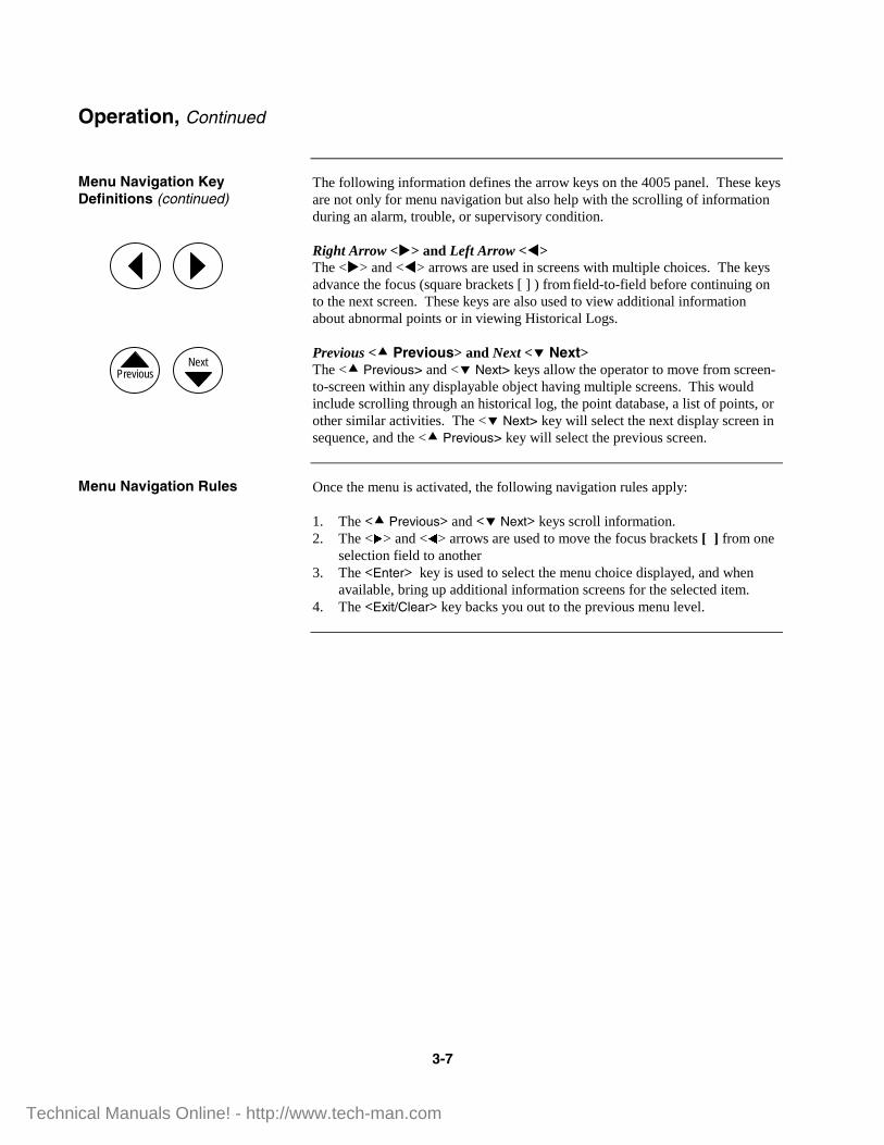
The following information defines the arrow keys on the 4005 panel. These keys are not only for menu navigation but also help with the scrolling of information during an alarm, trouble, or supervisory condition. Right Arrow <�> and Left Arrow <�> The <�> and <�> arrows are used in screens with multiple choices. The keys advance the focus (square brackets [ ] ) from field-to-field before continuing on to the next screen. These keys are also used to view additional information about abnormal points or in viewing Historical Logs. Previous <� Previous> and Next <� Next> The <� Previous> and <� Next> keys allow the operator to move from screen-to-screen within any displayable object having multiple screens. This would include scrolling through an historical log, the point database, a list of points, or other similar activities. The <� Next> key will select the next display screen in sequence, and the <� Previous> key will select the previous screen.
Once the menu is activated, the following navigation rules apply: 1. The <� Previous> and <� Next> keys scroll information. 2. The <u> and <t> arrows are used to move the focus brackets [ ] from one
selection field to another 3. The <Enter> key is used to select the menu choice displayed, and when
available, bring up additional information screens for the selected item. 4. The <Exit/Clear> key backs you out to the previous menu level.
Operation, Continued
Menu Navigation Key Definitions (continued)
Menu Navigation Rules
Next Previous
Technical Manuals Online! - http://www.tech-man.com

3-8
When an abnormal condition occurs, at least one of the panel LEDs begins to flash and the tone-alert sounds. The panel display shows the total number of abnormal conditions present in the system. At a glance, you know how serious the situation is by reading the number of abnormal conditions displayed (see Figure 3-3).
Figure 3-3. Abnormal Condition Display
Press the appropriate <ACK> key (under the corresponding flashing LED) to view the abnormal condition and silence the tone-alert. The 4005 also creates a “list” when abnormal conditions exist. The list contains the number of abnormal conditions present in the system.
When a Fire Alarm Condition is detected by the system, the FIRE ALARM LED flashes and the tone-alert sounds. For Supervisory and Trouble Conditions, the appropriate panel LED flashes, and the tone-alert sounds and remains ON without pulsing.
The 4005 is a Global Acknowledged System which means ONE (1) press of an <ACK> key globally acknowledges every abnormal point in the system in that category. If all the points are acknowledged in this manner, an appropriate message is displayed. When a point is acknowledged, the appropriate LED remains ON and the tone-alert is silenced. The total number of alarm, trouble, and supervisory conditions is shown in an alternating sequence on the display along with a prompt to the press <ACK> for point review. Pressing <ACK> scrolls through the selected list in chronological order. Each list is different and contains information concerning a particular abnormal condition. In some cases, additional information is available on the condition by pressing <�> or <�>. Note: Refer to the Single-Sheet Operating Instructions in
Appendix C for additional information.
Continued on next page
Handling Abnormal Conditions
Abnormal Conditions
Acknowledging an Alarm, Trouble, or Supervisory Condition
������� �� ��!������� ���" ��#������" ���� $%&&��'(�)��$%*+%,�
Three Troubles indicated
�+$&)��-��$��.&)�/+��� �����������0%�1%)%2)�$� �$��3-%� �4#�
Technical Manuals Online! - http://www.tech-man.com

3-9
When an alarm conditions exists, various signals, auxiliary relays, the city connection, and the tone-alert may activate, depending on the system configuration and the stage of the alarm condition. CAUTION: Pressing the Alarm Silence key causes fire alarm evacuation
signals to turn OFF. Follow local procedures to silence alarm evacuation signals.
To silence an alarm, perform the following:
Press the <ALARM SILENCE> key.
The <ALARM SILENCE> key, when pressed, turns OFF all circuits programmed to follow the Alarm Silence key.
The ALARM SILENCED LED turns ON and remains ON.
Note: If Waterflow/Sprinkler Devices are activated, notification appliances may or may not be silenced (depending on local code requirements). Usually, a dedicated bell continues to sound to indicate waterflow.
The <SYSTEM RESET> key is used to return the system to its normal state after an alarm condition has been cleared. When the <SYSTEM RESET> key is pressed, it causes any latched circuits to reset automatically. This also resets initiating devices, relays (including the city relay), notification appliances, and all LEDs and indicators which are programmed to reset with the <SYSTEM RESET> key. The message, SYSTEM RESET IN PROGRESS, is displayed when the key is pressed.
To reset the system, perform the following steps:
1. Restore/replace all affected devices in accordance with the instructions provided with each device.
2. Press the <SYSTEM RESET> key. If a zone stays in alarm during the reset period, the system reset is aborted, and the system remains in an alarm state. The display indicates the total number of alarms present in the system along with a prompt to use the <ACK> key to review the points. These points do not require acknowledgment. The alarm LED remains ON to indicate that a device is still in an alarm condition. If the system does not reset, and the display still shows an alarm although no alarm condition exists, read the display to determine the type of device and the zone number in alarm. Follow local procedures to investigate the area of the building with the alarm. Look for devices still in alarm. Most devices latch until they are reset, either by the system or manually.
Continued on next page
Handling Abnormal Conditions, Continued
How to Silence Alarms
How to Reset the System
Technical Manuals Online! - http://www.tech-man.com

3-10
The CPU Warm Start button (SW1) located beneath the main display is used to return the system to its normal state while preserving historical logs, enable/disable states of points, and the time. When warm starting the 4005, a Warm Start / Check Time and Date trouble occurs that clears upon acknowledgment. A warm start is the primary operation used to clear the Simplex Service Mode trouble.
Handling Abnormal Conditions, Continued
How to Warm Start the System
Technical Manuals Online! - http://www.tech-man.com

3-11
Various Functions may be passcode protected to prevent access by unauthorized personnel. Passcodes are provided to the user during system installation. To change or receive additional information concerning your passcodes, contact your local Simplex Branch Office.
The Menu and its sub-menus (for Access Level 1) are shown in Figure 3-4 below.
TOP LEVEL VIEW POINTS MONITOR
RELAY
SIGNAL
DIGITAL
ANALOG
HISTORY LOG ALARMS
TROUBLES
COMBINED
SOFTWARE REVISION
PASSCODE LOGIN
LOGOUT
GENERIC OUTPUT
GENERIC INPUT
SYSTEM POINTS
LIST
Figure 3-4. Menu Structure (Access Level 1)
The 4005 has three passcode-protected login levels (Level 1 Operations do not require a Passcode). Logging in at Level 4 causes a Service Trouble that cannot be cleared without a warm or cold start of the 4005. The default operations and their passcodes are shown in Table 3-2 below.
Table 3-2. Login Levels (Access Levels)
LEVEL OPERATIONS LEVEL OPERATIONS 1
Alarm Acknowledge Trouble Acknowledge Supervisory Acknowledge Alarm Silence System Reset View Points and Logs Passcode (Log In / Log Out) Software Revision
3
All Level 1 & 2 Operations Clear Logs Clear Verification Tallies Walk Test Programming:
Edit/Clear Point Label Restore/Save CFIG
2
All Level 1 Operations Set Time/Date Enable/Disable Points
4
All Level 1,2, & 3 Operations Cold Start Programming:
Edit Cards Edit SMPL Program System Options Edit Access Level
Continued on next page
Passcodes and Access Levels
Overview
Menu Structure
Login\Logout (Passcodes and Access Levels)
Technical Manuals Online! - http://www.tech-man.com

3-12
To Log In, perform the following steps on a 4005 that is at the High-Level Status screen (**SYSTEM IS NORMAL**): 1. Obtain the appropriate passcode information.
Note: All passcodes consist of a four-digit number. When moving from one digit to the next, an asterisk (∗) appears in the place of an entered number for security purposes.
2. Press <Menu>.
3. Press and hold <�Next> until [Passcode] is displayed, and then press <Enter>.
4. Press and hold <�Next> until [Log In] is displayed, and then press <Enter>.
5. Press <�Next> to scroll through the numbers on the display until the appropriate number is displayed.
6. Press the right arrow <�> to move the focus brackets [ ] to the next digit in the passcode.
Repeat Steps 5 & 6 until all numbers are entered.
7. When the passcode is correct, press <Enter> to Log In.
To Log Out, perform Steps 1 through 4 above except for Step 4 where you need to press and hold <�Next> until [Log Out] is displayed. Note: When the keypad is inactive for 10 minutes, the 4005 defaults to
Level 1.
Continued on next page
Passcodes and Access Levels, Continued
Logging In / Out
Technical Manuals Online! - http://www.tech-man.com
3-13
The 4005 has three logs: Alarm, Trouble, and Combined (Alarm & Trouble). The Alarm log allows 50 entries while saving information about the event and the time of the event.
Events stored in the Alarm log include:
• Alarms • Global Alarm Ack • Log cleared • Alarm Silence • System Reset
The Trouble log allows 100 entries while saving information about the event and the time of the event.
Events stored in the Trouble log include:
• All card and system troubles • Log-in/out for levels greater than Level 1 • Log cleared • Supervisory Conditions • Walk Test (alarm and trouble) - enabled from Walk Test menu
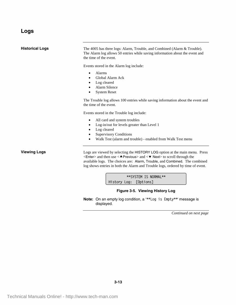
Logs are viewed by selecting the HISTORY LOG option at the main menu. Press <Enter> and then use <�Previous> and <� Next> to scroll through the available logs. The choices are: Alarm, Trouble, and Combined. The combined log shows entries in both the Alarm and Trouble logs, ordered by time of event.
Figure 3-5. Viewing History Log
Note: On an empty log condition, a ‘�� ���+&����)6��’ message is displayed.
Continued on next page
Logs
Historical Logs
Viewing Logs
��������������� ���7+&)�$6� �����8�)+��&9�
Technical Manuals Online! - http://www.tech-man.com
3-14
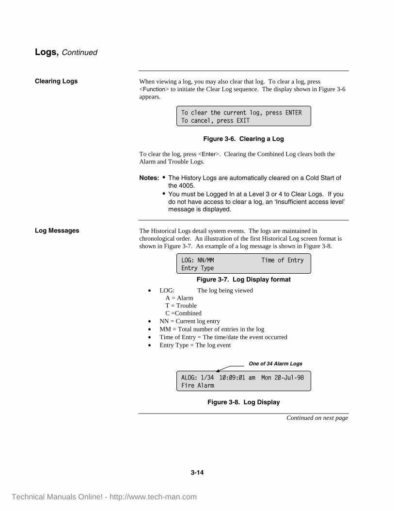
When viewing a log, you may also clear that log. To clear a log, press <Function> to initiate the Clear Log sequence. The display shown in Figure 3-6 appears.
Figure 3-6. Clearing a Log
To clear the log, press <Enter>. Clearing the Combined Log clears both the Alarm and Trouble Logs. Notes: • The History Logs are automatically cleared on a Cold Start of
the 4005. • You must be Logged In at a Level 3 or 4 to Clear Logs. If you
do not have access to clear a log, an ‘Insufficient access level’ message is displayed.
The Historical Logs detail system events. The logs are maintained in chronological order. An illustration of the first Historical Log screen format is shown in Figure 3-7. An example of a log message is shown in Figure 3-8.
Figure 3-7. Log Display format
• LOG: The log being viewed A = Alarm T = Trouble C =Combined • NN = Current log entry • MM = Total number of entries in the log • Time of Entry = The time/date the event occurred • Entry Type = The log event
Figure 3-8. Log Display
Continued on next page
Logs, Continued
Clearing Logs
Log Messages
���2-%.$�):%�2�$$%�)�-��;��$%&&���������2.�2%-;��$%&&��<���
=��4��� �+�%��5���)$6���)$6��6�%�
� =���4#>� ���������.����������?�-�����+$%��-.$��
One of 34 Alarm Logs
Technical Manuals Online! - http://www.tech-man.com

3-15
Figure 3-9 illustrates a secondary screen format that may appear with some log entries. Figure 15 shows an example of a secondary screen. To access a secondary screen, press <�> or <�> once the desired log is displayed.
Figure 3-9. Secondary Log Display Format
Figure 3-10. Secondary Log Display
Logs, Continued
Log Messages (continued)
������������� �������� �� ���������
/%&)�/+������%@��+$%����+)�$�A��%� �+$%��-.$��
Technical Manuals Online! - http://www.tech-man.com
3-16
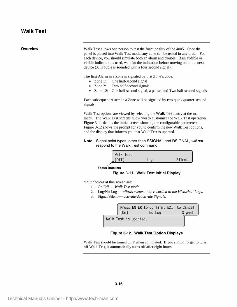
Walk Test allows one person to test the functionality of the 4005. Once the panel is placed into Walk Test mode, any zone can be tested in any order. For each device, you should simulate both an alarm and trouble. If an audible or visible indication is used, wait for the indication before moving on to the next device (A Trouble is sounded with a four second signal). The first Alarm in a Zone is signaled by that Zone’s code:
• Zone 1: One half-second signal • Zone 2: Two half-second signals • Zone 12: One half-second signal, a pause, and Two half-second signals
Each subsequent Alarm in a Zone will be signaled by two quick quarter-second signals. Walk Test options are viewed by selecting the Walk Test entry at the main menu. The Walk Test screens allow you to customize the Walk Test operation. Figure 3-11 details the initial screen showing the configurable parameters. Figure 3-12 shows the prompt for you to confirm the new Walk Test options, and the display that informs you that Walk Test is updated. Note: Signal point types, other than SSIGNAL and RSIGNAL, will not
respond to the Walk Test command.
Figure 3-11. Walk Test Initial Display Your choices at this screen are: 1. On/Off Walk Test mode. 2. Log/No Log allows events to be recorded to the Historical Logs. 3. Signal/Silent activate/deactivate Signals.
Figure 3-12. Walk Test Option Displays Walk Test should be truned OFF when completed. If you should forget to turn off Walk Test, it automatically turns off after eight hours.
Walk Test
Overview
/.-0��%&)�8559� ��� �+-%�)�
Focus Brackets
$%&&������)��'��5+$�;��<���)��'.�2%-�8�9� �� ��� �+��.-�
/.-0��%&)�+&���B.)%BC�C�C�
Technical Manuals Online! - http://www.tech-man.com

3-17
The 4005 allows you to view each configured point in the system and, depending on your access level, control and disable/enable the point you are viewing. This section describes how to view, control, and disable/enable points.
To view a specific point, press <Menu>, press <�Next> or <� Previous> to choose the VIEW POINTS option, and then press <Enter>. The points are arranged in the menu structure as shown in Figure 3-4 (page 3-11). To navigate the point database, press <�Next> or <� Previous> to scroll up and down through the points. Note: Pressing and holding <�Next> or <�Previous> allows the list to
scroll without sounding the tone-alert.
Continued on next page
Control / View Points
Overview
View a Point or List
Technical Manuals Online! - http://www.tech-man.com
3-18
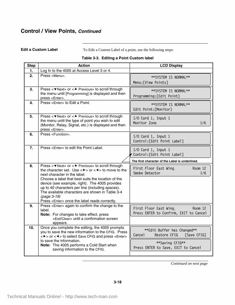
To Edit a Custom Label of a point, use the following steps:
Table 3-3. Editing a Point Custom label
Step Action LCD Display 1. Log In to the 4005 at Access Level 3 or 4. 2. Press <Menu>.
3. Press <�Next> or <� Previous> to scroll through the menu until [Programming] is displayed and then press <Enter>.
4. Press <Enter> to Edit a Point.
5. Press <�Next> or <� Previous> to scroll through the menu until the type of point you wish to edit (Monitor, Relay, Signal, etc.) is displayed and then press <Enter>.
6. Press <Function>.
7. Press <Enter> to edit the Point Label.
The first character of the Label is underlined.
8. Press <�Next> or <� Previous> to scroll through the character set. Use <�> or <�> to move to the next character in the label. Choose a label that best suits the location of the device (see example, right). The 4005 provides up to 40 characters per line (including spaces). The available characters are shown in Table 3-4 (page 3-19) Press <Enter> once the label reads correctly.
9. Press <Enter> again to confirm the change to the label. Note: For changes to take effect, press
<Exit/Clear> until a confirmation screen appears.
10. Once you complete the editing, the 4005 prompts you to save the new information to the CFIG. Press <�> or <�> to select Save CFIG and press <Enter> to save the information. Note: The 4005 performs a Cold Start when
saving information to the CFIG.
Continued on next page
Control / View Points, Continued
Edit a Custom Label
��������������� ����%���8!+%,� �+�)&9�
�4�'.$B��;�����)���'��)$�-�8�B+)� �+�)� .3%-9�
�+$&)��-��$��.&)�/+������� �����������0%�1%)%2)�$�� � �4D�
��������������� ����B+)� �+�)�8���+)�$9�
��������������� ��� $��$.��+���8�B+)� �+�)9�
�4�'.$B��;�����)������+)�$�A��%� �4D�
�4�'.$B��;�����)���'��)$�-�8�B+)� �+�)� .3%-9�
�+$&)��-��$��.&)�/+������� �������� $%&&������)��'��5+$�;��<���)��'.�2%-�
���B+)�"�55%$�:.&�':.��%B���'.�2%-� �%&)�$%�'��=� 8�.*%�'��=9�
���.*+���'��=��� $%&&������)���.*%;��<���)��'.�2%-�
Technical Manuals Online! - http://www.tech-man.com

3-19
Table 3-4 describes the character set which can be used for creating Custom Point labels.
Table 3-4. Custom Point Label Characters
Type of character Available Characters Digits 0 - 9 Alpha A – Z and a - z Punctuation space comma period
& ‘ ) ( * + - / : Note: Press <Menu> to toggle between Upper and Lower
case characters. Press <Disable/Enable> to insert a blank space.
When an abnormal condition exists in the 4005, the system displays the abnormal point automatically. After pressing <ACK>, you can disable that point by pressing <Disable/Enable>. Note: You must be logged in at a Level 2 or greater to Disable/Enable
points.
Continued on next page
Control / View Points, Continued
Custom Point Label Characters
Disabling an Active Point
Technical Manuals Online! - http://www.tech-man.com

3-20
Points can be viewed and Disabled/Enabled by following the steps shown in Table 3-5.
Table 3-5. Viewing and Disabling/Enabling a Point
Step Action LCD Display 1. Log In to the 4005 at Access Level 2, 3, or 4. 2. From the High-Level Status display, press <Menu>.
3. Press <�Next> or <� Previous> to scroll through the menu until [View Point] is displayed and then press <Enter>.
4. Press <�Next> or <� Previous> to select the desired point type and then press <Enter>.
5. Press <�Next> or <� Previous> to select the desired point and then press <Disable/Enable>.
6. Press <�Next> or <� Previous> to scroll from Enable to Disable and then press <Enter>.
7. Press <Enter> again to confirm your choice.
IMPORTANT: Refer to the warnings at the beginning of this manual
before using the Disable function.
Choosing Disable removes positive voltage from the zone. Choosing Enable provides a 30-second countdown before a point enables.
Control / View Points, Continued
Disable/Enable a Point
��������������� ����������������%�� �#�?�-����
��������������� ����%���8!+%,� �+�)9�
��������������� ���!+%,� �+�)�8���+)�$9�
'-.&&$����#>� �$.+�+���'%�)%$����+)�$�A�� ��� � �4��
'-.&&$����#>� �$.+�+���'%�)%$�'��)$�-��8��.3-%9� �).)�&���.3-%B�
Technical Manuals Online! - http://www.tech-man.com

3-21
The Function Menu displays commonly used control functions described below in Table 3-6.
Table 3-6. Function Menu Options
Function Description Access Level
Manual Evacuation Activates the Manual Evacuation operation (NACs activate and Fire Alarm LED flashes until <ACK> is pressed.
3 or 4
City Circuit Disconnect Disconnects the City Circuit. 3 or 4 Control Point Bypass Bypasses the following Control
Points: • On until Silence signal • Resettable signals • AHU outputs
3 or 4
Elevator Bypass Bypasses the Elevator Recall. 3 or 4 Doorholder Bypass Bypasses the Doorholder
operation. 3 or 4
Lamp Test Illuminates all LEDs and all LCD segments on the display.
1 – 4
Table 3-7 describes the steps to access Manual Evacuation.
Table 3-7. Manual Evacuation
Step Action LCD Display 1. Log In to the 4005 at Access Level 3 or 4. 2. From the High-Level Status display, press
<Function>.
3. Press <�Next> or <� Previous> to scroll through the menu until [Manual Evacuation] is displayed and then press <Enter>.
4. Press <�Next> or <� Previous> to select [On] or [Off] and then press <Enter>.
5. Press <Enter> again to confirm your choice. 6. If [On] is selected in step 4, the display shown at
the right appears and the Manual Evacuation begins.
To turn OFF Manual Evacuation: Repeat steps 1 – 5 above then press
<SYSTEM RESET>
Continued on next page
Function Menu
Overview
Manual Evacuation
��������������� ��������������� ��%��#�?�-����
��������������� ���'��)$�-�8�.��.-��*.2�.)+��9�
�.��.-��*.2�.)+���'��)$�-�8559� �).)�&����
�.��.-��*.2�.)+����+$%� �+�)� � ���
Technical Manuals Online! - http://www.tech-man.com

3-22
Table 3-8 describes the steps to access the City Circuit Disconnect.
Table 3-8. City Circuit Disconnect
Step Action LCD Display 1. Log In to the 4005 at Access Level 3 or 4. 2. From the High-Level Status display, press
<Function>.
3. Press <�Next> or <� Previous> to scroll through the menu until [City Circuit Disconnect] is displayed and then press <Enter>.
4. Press <�Next> or <� Previous> to select [On] or [Off] and then press <Enter>.
5. Press <Enter> again to confirm your choice. 6. If [Off] is selected in step 4, the display shown at
the right appears, the city circuit disconnects, and a trouble is displayed.
7. Press <Enter> again to confirm your choice.
Table 3-9 describes the steps to access the Control Point Bypass.
Table 3-9. Control Point Bypass
Step Action LCD Display 1. Log In to the 4005 at Access Level 3 or 4. 2. From the High-Level Status display, press
<Function>.
3. Press <�Next> or <� Previous> to scroll through the menu until [Control Point Bypass] is displayed and then press <Enter>.
4. Press <�Next> or <� Previous> to select [On] or [Off] and then press <Enter>.
5. Press <Enter> again to confirm your choice. 6. If [On] is selected in step 4, the display shown at
the right appears, the control point is bypassed, and a trouble is displayed.
7. Press <Enter> again to confirm your choice.
Continued on next page
Function Menu, Continued
City Circuit Disconnect
Control Point Bypass
��������������� ����������������%�� �#�?�-����
��������������� ���'��)$�-�8'+)6�'+$2�+)�1+&2���%2)9�
'+)6�'+$2�+)�1+&2���%2)�'��)$�-�8559� �).)�&��
'+)6�'+$2�+)�1+&2���%2)��$��3-%� �+�)� ���" �� �4��
��������������� �������#������� /%B����?�-����
��������������� ���'��)$�-�8'��)$�-� �+�)�"6�.&&9�
'��)$�-� �+�)�"6�.&&�'��)$�-�8559� �).)�&����
'��)$�-���+�)�"6�.&&��$��3-%� �+�)� ���" �� �4��
Technical Manuals Online! - http://www.tech-man.com

3-23
Table 3-10 describes the steps to access the Elevator Bypass.
Table 3-10. Elevator Bypass
Step Action LCD Display 1. Log In to the 4005 at Access Level 3 or 4. 2. From the High-Level Status display, press
<Function>.
3. Press <�Next> or <� Previous> to scroll through the menu until [Elevator Bypass] is displayed and then press <Enter>.
4. Press <�Next> or <� Previous> to select [On] or [Off] and then press <Enter>.
5. Press <Enter> again to confirm your choice. 6. If [On] is selected in step 4, the display shown at
the right appears and a trouble is displayed.
7. Press <Enter> again to confirm your choice.
Table 3-11 describes the steps to access the Doorholder Bypass.
Table 3-11. Doorholder Bypass
Step Action LCD Display 1. Log In to the 4005 at Access Level 3 or 4. 2. From the High-Level Status display, press
<Function>.
3. Press <�Next> or <� Previous> to scroll through the menu until [Doorholder Bypass] is displayed and then press <Enter>.
4. Press <�Next> or <� Previous> to select [On] or [Off] and then press <Enter>.
5. Press <Enter> again to confirm your choice. 6. If [On] is selected in step 4, the display shown at
the right appears and a trouble is displayed.
7. Press <Enter> again to confirm your choice.
To reverse Doorholder Bypass: Repeat steps 1 – 5 above then press
<SYSTEM RESET>
Continued on next page
Function Menu, Continued
Elevator Bypass
Doorholder Bypass
��������������� ����������>.��� /%B����?�-����
��������������� ���'��)$�-�8�-%*.)�$�"6�.&&9�
�-%*.)�$�"6�.&&�'��)$�-�8559� �).)�&����
�-%*.)�$�"6�.&&��$��3-%� �+�)� ���" �� �4��
��������������� �������#������/%B�� ���?�-����
��������������� ���'��)$�-�81��$:�-B%$�"6�.&&9�
1��$:�-B%$�"6�.&&�'��)$�-�8559� �).)�&����
1��$:�-B%$�"6�.&&��$��3-%� �+�)� ���" �� �4��
Technical Manuals Online! - http://www.tech-man.com

3-24
Table 3-12 describes the steps to access the Lamp Test.
Table 3-12. Lamp Test
Step Action LCD Display 1. Log In to the 4005 at Access Level 1, 2, 3, or 4. 2. From the High-Level Status display, press
<Function>.
3. Press <�Next> or <� Previous> to scroll through the menu until [Lamp Test] is displayed and then press <Enter>.
4. All LEDs on the control panel and all LCD segments on the display illuminate.
Function Menu, Continued
Lamp Test
��������������� �����������.��� �$+��>�?�-����
��������������� ���'��)$�-�8 .����%&)9�
���������������������������������������������������������������������������������
Technical Manuals Online! - http://www.tech-man.com

Appendix A-1
Alarm: A warning of fire danger.
Alarm Signal: A signal indicating an emergency requiring immediate action, such as a signal indicative of fire.
Alarm Verification: A feature to reduce unwanted alarms wherein current-limited devices, typically smoke detectors, must report alarm conditions for a minimum period of time, or confirm alarm conditions within a given time period after being reset to be accepted as a valid alarm initiation signal.
Authority Having Jurisdiction (AHJ): The “authority having jurisdiction” is the organization, office, or individual responsible for approving equipment, an installation, or a procedure.
Class A: A four-wire method of connecting IDC or NAC that guarantees operation with a single open or grounded conductor. See Style D (IDC) and Style Z (NAC).
Class B: A two-wire method of connecting IDC or NAC that will cause a trouble indication with an open circuit. See Style B (IDC) and Style Y (NAC).
Current-Limited IDC State: A “current-limited” state exists when an initiating device shunts a resistor across the IDC.
Digital Alarm Communicator Transmitter (DACT): A system component at the protected premises to which initiating devices or groups of devices are connected. The DACT will seize the connected telephone line, dial a pre-selected number to connect to a DACR, and transmit signals indicating a status change of the initiating device.
Display: The visual representation of output data other than printed copy.
Evacuation: The withdrawal of occupants from a building.
Evacuation Signal: A distinctive signal intended to be recognized by the occupants as requiring evacuation of the building.
FACP: Fire Alarm Control Panel. A system component that receives input from automatic and manual fire alarm devices. The control panel may also provide transfer of power to the notification appliances and transfer of conditions to relays or devices connected to the control panel.
Fire/Supervisory: An IDC point type that is zone selectable. This point type will initiate a “Supervisory Abnormal” condition at the FACP if a current-limited state is detected and a Fire Alarm condition if a shorted state is detected.
Continued on next page
Appendix A
Glossary of Terms
Technical Manuals Online! - http://www.tech-man.com

Appendix A-2
Heat Detector: A device that detects abnormally high temperature or rate of temperature rise.
Initiating Device: A system component that originates transmission of a change of state condition, such as a smoke detector, manual fire alarm box, supervisory switch, etc.
Initiating Device Circuit (IDC): A circuit to which automatic or manual initiating devices are connected where the signal received does not identify the individual device operated.
Intrinsically Safe: Equipment designed to limit the amount of electrical energy so that any spark or thermal effect is incapable of causing ignition of a mixture of flammable or combustible material in air under prescribed test conditions. Simplex Intrinsically Safe equipment is Factory Mutual Approved for all Hazardous (Classified) Locations in accordance with Article 500 of the National Electrical Code, NFPA 70. Labeled: Equipment or materials to which has been attached a label, symbol, or other identifying mark of an organization acceptable to the “authority having jurisdiction” and concerned with product evaluation, that maintains periodic inspection of production labeled equipment or materials and by whose labeling the manufacturer indicates compliance with appropriate standards or performance in a specified manner.
Listed: Equipment or materials included in a list published by an organization acceptable to the “authority having jurisdiction” and concerned with product evaluation, that maintains periodic inspection of production of listed equipment or materials and whose listing states either that the equipment or material meets appropriate standards or has been tested and found suitable for use in a specified manner.
Local Fire Alarm System (formerly NFPA 72 A): A Fire Alarm system where occupants are alerted of a fire condition via local Notification Appliances. March Time Code: A notification code that consists of a 50% duty cycle pulse train. The march time rate is specified in Beats Per Minute (BPM). A Slow March Time code consists of 20 ON/OFF cycles in one minute. A March Time code consists of 120 ON/OFF cycles in one minute. Municipal Master Box: An initiating device intended to send an alarm condition to the public fire service communications center.
Normal State (IDC): The normal state is defined as the end-of-line resistor in place with the full range of line resistance and detector load. Notification Appliance: A fire alarm system component such as a bell, horn, strobe, etc., that provides an audible or visible output, or both.
Notification Appliance Circuit (NAC): A circuit or path directly connected to one or more notification appliances.
Continued on next page
Glossary of Terms, Continued
Technical Manuals Online! - http://www.tech-man.com

Appendix A-3
Open Circuit State (IDC): An open circuit is defined as the absence of the end-of-line resistor, with or without a detector load.
Protected Premises: The physical location protected by a fire alarm system. Remote Master Box: An initiating device intended to send alarm, supervisory, and trouble signals to a remote location at which appropriate action is taken.
Short Circuit IDC State: A short circuit state exists when an initiating device shunts a low resistance contact across the IDC. The contact resistance is defined as 0-200 ohms.
Simple Code: A code consisting of a distinct number of pulses used to indicate which zone (IDC) is in alarm. The number of pulses is the same as the number assigned to the zone in alarm.
Smoke Detector: A device that detects visible or invisible particles of combustion.
States (IDC): The state of an IDC is determined by the physical condition of the wiring and devices connected to the terminal block. There are four states associated with an IDC:
• Short (0-200 ohms) • Current-Limited state (400-820 ohms), across the initiating
device circuit • Normal state (defined as the end-of-line resistor in place with
the full range of line resistance and detector load). • Open circuit state (defined as the absence of the end-of-line
resistor, with or without a detector load). Style B: A method of connection for IDC that will provide a trouble indication in the event of an open circuit on the wiring loop. Also known as Class B.
Style C/Style E: An IDC point type. A trouble indication is provided if a short (+ to -) or open circuit condition exists on the wiring loop. An alarm is initiated if a “current-limited” state exists. Style C is two-wire; Style E is four-wire.
Style D: A method of connecting initiating devices on IDCs that provide multiple signal paths so that circuit operation is maintained with a single open circuit or ground connection. A trouble indication is provided in the event of an open circuit on the wiring loop. Also known as Class A.
Style Y: A method of connecting notification appliances on NACs that provide a trouble indication in the event of an open circuit on the wiring loop. Also known as Class B.
Continued on next page
Glossary of Terms, Continued
Technical Manuals Online! - http://www.tech-man.com

Appendix A-4
Style Z: A method of connecting notification appliances on NACs that provide multiple signal paths so that circuit operation is maintained with a single open circuit or ground connection. A trouble indication is provided in the event of an open circuit on the wiring loop. Also known as Class A.
Supervisory Signal: A signal indicating the need of action in connection with the fire suppression system or equipment, or with the maintenance features of related systems. Temporal Code: A three-pulse coding pattern adopted by NFPA as a standard evacuation pattern for audible notification. The pattern consists of three 1/2-second pulses, each pulse separated by 1/2-second silence. Each group of three pulses is separated by 1.5 seconds of silence.
VSMOKE: A point type that is selectable for an IDC. This point type will initiate an immediate alarm from a contact closure Pull Station or Heat Detector, but will initiate the Alarm Verification sequence for a current-limited alarm. A point configured as VSMOKE must not have any devices other than smoke detectors that initiate a current-limited alarm.
Zone: A defined area within the protected premises. A zone may define an area from which a signal can be received, an area to which a signal can be sent, or an area in which a form of control can be executed.
Glossary of Terms, Continued
Technical Manuals Online! - http://www.tech-man.com

Appendix B-1
The 4005 is listed for the following listing categories. UL 864 Listings for Type of System:
• UL 864 Power-Limited Fire Alarm Control Unit.
• Local (formerly NFPA 72A). Requires the sounding of an alarm via listed notification
appliance(s).
• Auxiliary (formerly NFPA 72B). Requires 4005-9809 City Circuit Module.
• Remote Station - protected premise (formerly NFPA 72C). Requires 4005-9809 City Circuit Module or the 4005-9810
DACT.
• Proprietary - protected premise (formerly NFPA 72D). Requires 4005-9809 City Circuit Module.
• Central Station - protected premise (formerly NFPA 71). Requires 4005-9810 DACT.
UL 864 Listings for Type of Service:
• Automatic, Manual, Waterflow, and Sprinkler Supervisory. UL 864 Listings for Type of Signaling:
• Coded, Non-Coded, March-Time and DACT. DACT requires 4005-9810 DACT.
• Same as UL above, and • Intrinsically Safe (Requires 2081-9636, 2081-9062, or 2081-9063
Intrinsically Safe Barrier Module)
• CSFM • MEA
Appendix B Regulatory Information
NFPA Standards
Factory Mutual Approved
Local Approvals
Technical Manuals Online! - http://www.tech-man.com

Appendix B-2
The 1993 National Fire Alarm Code (NFPA 72) referenced publications are listed below. The installer should be familiar with these codes, as well as any applicable local codes and standards, when installing a fire alarm system. • NFPA 72 National Fire Alarm Code • NFPA 11 Standard for Low-Expansion Foam and Combined
Agent Systems • NFPA 11A Standard for Medium- and High-Expansion Foam
Systems • NFPA 12 Standard on Carbon Dioxide Extinguishing Systems • NFPA 12B Standard on Halon 1211 Fire Extinguishing Systems • NFPA 13 Standard for the Installation of Sprinkler Systems • NFPA 14 Standard for the Installation of Standpipe and Hose
Systems • NFPA 15 Standard for Water Spray Fixed Systems for Fire
Protection • NFPA 17 Standard for Dry Chemical Extinguishing Systems • NFPA 70 National Electrical Code • NFPA 80 Standard for Fire Doors and Fire Windows • NFPA 90A Standard for the Installation of Air Conditioning and
Ventilation Systems • NFPA 90B Standard for the Installation of Warm Air Heating and
Air Conditioning Systems • NFPA 92A Recommended Practice for Smoke-Control Systems • NFPA 92B Guide for Smoke Management Systems in Malls, Atria,
and Large Areas • NFPA 101 Life Safety Code • NFPA 170 Standard for Fire Safety Symbols • NFPA 231C Standard for Rack Storage of Materials • NFPA 1221 Standard on the Installation, Maintenance, and Use of
Public Fire Service Communication Systems
Installation Requirements
Codes and Standards
Technical Manuals Online! - http://www.tech-man.com

Appendix C-1
The instruction sheet on the reverse side of this page is a replica of the instruction sheet which is shipped with the 4005 Fire Alarm. This sheet is intended to be framed and mounted adjacent to the control panel for ready reference.
Continued on next page
Appendix C Single Sheet Operating Instructions
Single Sheet Operating Instruction Use
Technical Manuals Online! - http://www.tech-man.com

YOUR SAFETY AND THE SAFETY OF THOSE AROUND YOU ALWAYS COMES FIRST. Actions taken during a fire depend upon local practices. Be sure you know what to do.
ALARM TROUBLE / SUPERVISORY
RED LED IS FLASHING AND TONE-ALERT IS PULSING
FIRE = 3 SUPERVISORY = 0 TROUBLE = 0FIRE ZONES: 02 07 06
FIREALARM
ALARMACK
SYSTEMSUPERVISORY
SYSTEMTROUBLE
ALARMSILENCED
ACPOWER
SUPVACK
TROUBLEACK
ALARMSILENCE
SYSTEMRESET
Menu Function DisableEnable
Exit Clear Enter Previous
Next
RED ALARM LED(FLASHING)
ALARMACKNOWLEDGE
KEY
ALARMSILENCEKEY
SYSTEMRESETKEY
ALPHA-NUMERICDISPLAY
ALARMSILENCEDLED
1. Unlock and open the panel door. Read and follow the instructions on the display. It will toggle between Screens 1 and 2.
SCREEN 1
SCREEN 2
2. Press the (ALARM ACK) key under the flashing red LED. Read the alphanumeric display.
The tone-alert is silenced and the display shows pertinent report information, such as shown below.
SCREEN 3
3. Read the Alarm information on the display. Summon appropriate personnel to respond.
HOW TO SILENCE THE SIGNALS
4. Press the (ALARM SILENCE) key and read the display. The alphanumeric display shows signal status.
ALARM SILENCED LED turns ON steady.
HOW TO RESET THE SYSTEM
5. When the alarm condition clears, restore or replace all affected devices (smoke detectors, pull stations, etc.) in accordance with the instructions provided with each device.
6. Reset the system. Press the (SYSTEM RESET) key.
The system displays the following after a completed System Reset with no alarms present:
7. Press any key to return to the SYSTEM NORMAL screen.
YELLOW LED IS FLASHING AND TONE-ALERT IS ON STEADY
FIRE = 0 SUPERVISORY = 0 TROUBLE = 3** TROUBLE ** Press ACK to review
FIREALARM
ALARMACK
SYSTEMSUPERVISORY
SYSTEMTROUBLE
ALARMSILENCED
ACPOWER
SUPVACK
TROUBLEACK
ALARMSILENCE
SYSTEMRESET
Menu Function DisableEnable
Exit Clear Enter Previous
Next
ALPHA-NUMERICDISPLAY
LED (FLASHING)
YELLOWTROUBLE
TROUBLEACKNOWLEDGEKEY
Note: A Trouble Condition is described in this example. A Supervisory Condition is handled in a similar manner.
1. Unlock and open panel door. Read and follow the instructions on the display (see example below).
2. Press the (TROUBLE ACK) key under the flashing yellow LED. Read the Trouble information on the display (see example below).
3. Summon appropriate personnel to respond.
4. Response personnel should restore or replace the defective device (switch, wire, notification appliance, etc.) in accordance with device instructions. If necessary, press (SYSTEM RESET) when the
abnormal condition has been corrected. After a short delay, the system returns to normal and
displays the following.
Note: If your system configuration does not match this sheet, consult Simplex for specific operations. Simplex is listed in the Yellow Pages.
In case of trouble, notify: Name Address Phone#
THESE INSTRUCTIONS ARE INTENDED TO BE FRAMED AND MOUNTED ADJACENT TO THE CONTROL PANEL FOR READY REFERENCE.
See Operator’s Instruction Manual for detailed operation.
Technical Manuals Online! - http://www.tech-man.com

Technical Manuals Online! - http://www.tech-man.com

Rev. C Simplex Time Recorder Co., • Simplex Plaza • Gardner, Massachusetts 01441-0001 U.S.A. 574-068 Simplex International Time Equipment, Co., LTD. • Mississauga, Ontario, Canada
Technical Manuals Online! - http://www.tech-man.com