Installation and Operating Instructions - Crompton · PDF fileInstallation and Operating...
97
Installation and Operating Instructions System Protection Relay Energy Division Our commitment. Your advantage.
-
Upload
nguyennhan -
Category
Documents
-
view
239 -
download
1
Transcript of Installation and Operating Instructions - Crompton · PDF fileInstallation and Operating...

Installation and Operating Instructions
System Protection Relay
Energy Division
Our commitment. Your advantage.

System Protection Relay
Installation & Operating Manual
SPR – 013
SPR – 014
SPR Issue 6 03/08

Contents Page
COPYRIGHT 6WARNINGS and Cautions 6INTRODUCTION
General description 7INSTALLATION
Unpacking 8Damage check 8Contents check 8
Dimensions of the SPR 8Mounting notes 9
Connecting the SPR 10Contrast adjustment 10
Theory of operation and response time 11Watchdog relay 11Electromagnetic Compatability 11
OPERATING INSTRUCTIONS
General 12Default display 12Front panel controls 13
Menu navigation buttons 13LCD contrast control 13
Main menu 13Configuration menu 16
Relays 16Range 16Time and date 16System tag names 18Display timout feature 19Configuring the user screen 20Viewing the user screen 21Saving relay setup 22Event log menu 22
System configuration and relay status 23System configuration 23Bus readings 24Relay status 25
Relay protective trip functions 26General 26
Relay setting examples 27Setting up a relay contact 27Caption setting for relay configuration 29Logged 30Latched 30Alarm 30Failsafe 31Setting up an Alarm 34

Contents (Continued) Page
Latching a Relay 38Testing relay latch functions 41Event log 43Logical operators 45Time over current relay 49
Protective function detail 51Type 25 – Synchronising/synchronism-check 52Type 25D – Synchronising/synchronism-check with dead bus 53Type 27 – Under voltage 54Type 47 – Phase order (Phase sequence) 55Type 32R – Directional power (reverse) 55Type 47 – Voltage unbalance 56Type 51 – AC Time over current 57Time over current characteristics 58Standard inverse curve 59Very inverse curve 60Extremely inverse curve 61Type 51V – AC Time over current with voltage restraint 62Type 51G – Time over current neutral ground fault check 63Type 59 – Over voltage 65Type 81O – Over frequency 66Type 81U – Under frequency 66Logical trip functions 67Type 40Q reverse Var 68Type 50 instantaneous over current 68Type 50N over neutral current 69Type 37 instantaneous under current 70Type 46 phase balance current 70Type 32O directional (forward) over power 71
Power metering 72System configuration 72‘Generator’ checking 72Bus checking 74
Password protection 75Introduction 75Using the password features 75Installation level password – Level 3 75Unlocking a password 76If a password has been lost or forgotten 77Changing a password 77Switching off password levels 77Engineering password – Level 2 77Operator level password – Level 1 78Lockout password – Level 0 78Password levels 79

Contents (Continued) Page
RS485 digital output – MODBUS implementation 82Communication parameters 83Input registers 84Measurement registers 84Event log registers 85Holding registers 86System registers 86Relay registers 86Relay number 87Trip function 87Trip mode 87Trip status 88Trip parameters (1 to 6) 88RTC registers 88
PRODUCT SPECIFICATION 89Inputs 89Outputs 89Display 90Auxiliary supply (24V) 90Realtime clock 91Measuring ranges 91Accuracy and resolution 91Standards 92Environment 93Enclosure 93Serial Communications 94Specification approval 94
Tables1 Relay protective trip functions 20/422 Measurement registers 713 Event log registers 724 Relay registers 73
Fig1 Dimensions of the SPR 72 SPR back panel connections 83 SPR electrical connections 94 Time – current characteristic - standard inverse 505 Time – current characteristic - very inverse 516 Time – current characteristic - extremely inverse 527 Time – current characteristic - long time standby earth fault 64

6
COPYRIGHT
The copyright in this document (including all information contained therein) is owned byCROMPTON INSTRUMENTS and must be used solely for the owner’s specified purposes.
This document must not be copied or reproduced, nor divulged in whole or in part, without theowner’s written consent.
WARNINGS
1 The System Protection Relay is not intended to be used as a sole means of
protection - good engineering practice dictates that any critical function be
protected by two independent and diverse devices.
2 In the interest of safety and functionality this product must be installed by
qualified properly trained personnel abiding by local regulations.
3 Voltages dangerous to human life are present at some of the terminal
connections of this unit. Ensure that all supplies are de-energised before
attempting any connection or disconnection. External installations must be
sufficient to protect human life and equipment under fault conditions.
CAUTIONS
1 These products do not have internal fuses, therefore external fuses must
be used for protection for safety under fault conditions.
2 The current inputs of these products are designed for connection into
systems via current transformers only.
3 Never open-circuit the secondary winding of a current transformer. Always
ensure that the power is disconnected before separating the current
connector from SPR.
4 Internal self-checking circuitry (watchdog) continuously monitors the
operational state of the SPR, and operates a dedicated relay contact. If the
Watchdog relay is in the ‘failed’ condition (not energised) all other relay
contacts are forced to the de-energised condition.
5 Operation outside specified limits may cause permanent damage or
temporary disruption. For the latter case, normal operation may be
restored by temporary disconnection of the auxiliary supply.

7
INTRODUCTION
Traditionally, each protection requirement in a switchboard or generating set has been met withindividual protection relays. These relays have provided a reliable solution over many years, butwith the high number of products required in some applications, this can require large amountsof space within a panel. The SPR combines all of the popular protection relay functions into onecompact panel mounting product.
GENERAL DESCRIPTION
The System Protection Relay (SPR) is a microprocessor based unit which monitors three-phasevoltage and current signals and a single-phase voltage input and provides a number of userdefinable relay outputs which perform protective functions (see OPERATING INSTRUCTIONS –Protective Functions).
The unit is menu-controlled, which is achieved through the use of the front panel display andfour associated soft-touch controls (see OPERATING INSTRUCTIONS).
Because the SPR measures all of the fundamental electrical parameters, the microprocessor cancalculate other parameters and offer the user many more features and better protection.
Also included are functions which allow logical relationships between the measured parametersand the output relays
The main features of SPR are:
● 18 Protection Relay Functions❥ 9 Logical Relay Functions● 8 or 12 Change Over Relay (form C) Contacts● Digital Technology● Ease of Use● Accurate Settings ● RS485 Modbus Communications● Password Protection

8
INSTALLATION
UNPACKING
Carefully unpack the unit and immediately carry out a damage and contents check. Retain thepacking for possible future use, e.g. return to manufacturer for calibration.
Damage check
Carefully check that there are no signs of damage to the unit or associated connectors.
If signs of damage are found, report these to your local sales office as soon as possible.
Contents check
Check the contents of the package agree with the following contents list:● One SPR unit.● Operating Manual.● Screw clamp electrical connectors● Panel mounting clamps
DIMENSIONS OF THE SPR
The case dimensions are shown in Fig 1.
Fig 1 Dimensions of the SPR

9
MOUNTING NOTES
The SPR may be mounted in a panel of any thickness up to a maximum of 25mm (1").
Mounting is by screw clamps. Consideration should be given to the space required behind theunit to allow for bends in the connection cables.
As the enclosure conforms to IP54, the front panel is protected against ingress from water spray.Additional sealing to the panel may be obtained by the use of an optional gasket. The terminalsat the rear of the case are not IP rated, and must be protected from liquids.
The SPR should be mounted where the operating temperature is within the standard range of0°C to +50°C (+32°F to +122°F). Products are available with an extended operating temperaturerange of -20°C to +60°C (-4°F to +140°F) as a factory build option (specify when placing order).
If the SPR is to be mounted in a location where it will be subjected to direct sunlight, ensure thatany resulting temperature rise does not exceed the product’s operating temperature range.Vibration should be kept within specified operating limits. See full specification for details.
Labels are affixed to the product to indicate connection information and electrical data.
Connecting the SPR
The SPR back panel is shown in Fig 2, and the connections are shown in Fig 3.
Fig 2 SPR Back Panel Connections

Connecting the SPR
Wiring - Input connections are made directly to shrouded screw clamp terminals. Numbering isclearly marked on the case. Choice of cable should meet local regulations.
● Voltage , Communications and Relay terminals will accept 0.2 to 2.5mm2 (24 to12 AWG) diameter cables.
● Terminals for current inputs will accept up to 0.2 to 4.0mm2 (24 to 10 AWG) diameter cables.
Auxiliary Supply - SPR should ideally be powered by a dedicated class 2 power supply. The SPRsupply input must be protected by a 2 Amp HRC fuse. Ensure that the supply Voltage is withinthe working range for the auxiliary input. Refer to the products’ data label for input ratings.
Fusing - In addition to the Auxiliary Supply, it is recommended that all voltage input lines arefitted with 1 amp quick blow fuses. For UL approved installations, all fuses must be UL listed parts.
Earth/Ground Connections - The ground stud on the rear panel should be connected to a cleanground. For safety reasons, CT secondary connections should be grounded according toappropriate codes of practice.
The electrical connections are shown in Fig 3.
Model SPR-013 Model SPR-014
Fig 3 SPR Electrical Connections
Contrast adjustment
Contrast adjustment is available via the front panel keys. See customising information. This maybe necessary on installation to obtain the clearest display. Contrast is adjusted automatically tocompensate for changes in ambient temperature. WARNING: There is a possibility of the displaygoing blank if the manual contrast adjustment is set to extremes
10
Note: Do not use terminal 10-12.
11
THEORY OF OPERATION AND RESPONSE TIME
True RMS (Root Mean Square) measurements are calculated and displayed on the meteringscreen, and these measurements are also used to control the operation of the trip relays. Activepowers are calculated directly by multiplication of Voltage and current. Reactive powers arecalculated using a frequency corrected quarter-phase time delay method. SPR uses harmonicfiltered waveform zero crossings to synchronize the sampling scheme to the input frequency. Ifthe Voltage level on this input falls below the level at which the product can reliably determinethe frequency, the default frequency is used. SPR samples each Voltage and current input,building up a 32 sample buffer, which means that distorted waveforms with content up to 15thharmonic will be accurately measured.
The calculation of the RMS measurements and control of the trip relays takes approximately 90milliseconds, this is known as the "loop time". Once completed, the sampling / calculating /control process begins again. The typical response time for most trip functions is between 1 and2 loop times.
Where this differs for specific trip functions, further information can be found in thePROTECTIVE FUNCTION DETAIL section. The loop time can also be affected by intensiveModbus communications.
WATCHDOG RELAY
An internal watchdog circuit continuously monitors the operational state of the SPR, andoperates a dedicated relay contact. If the Watchdog relay is in the ‘failed’ condition (notenergised) all other relay contacts are forced to the de-energised condition.
ELECTROMAGNETIC COMPATIBILITY
This unit has been designed to provide protection against EM (electro-magnetic) interference inline with requirements of EU and other regulations. Precautions necessary to provide properoperation of this and adjacent equipment will be installation dependent and so the following canonly be general guidance:-
● Avoid routing wiring to this unit alongside cables and products that are, or could be, a source of interference.
• The auxuliary supply to the unit should not be subject to excessive interference. In somecases, a supply line filter may be required.
• To protect the product against incorrect operation or permananet damage, surge transients must be controlled. It is good EMC practice to suppress differential surges to 2kV or less at the source. The unit has been designed to automatically recover from typical transients, however in extreme circumstances it may be necessary to temporarilydisconnect the auxiliary supply for a period of greater than 5 seconds to restore correct operation.
• Screened communication and small signal leads are recommended and may be required. These and other connecting leads may require the fitting of RF suppression components, such as ferrite absorbers, line filters etc., if RF fields cause a problem.
• It is good practice to install sensitive electronic instruments that are performing critical functions in EMC enclosures that protect against electrical interference causing a disturbance in function.

12
OPERATING INSTRUCTIONS
GENERAL
Switch on the auxiliary supply. Followingcomprehensive diagnostic checks, andonce correct operation has been verified,the dedicated watchdog relay contactsenergize to indicate system operational.Once this is complete, the start-up screenwill be displayed for 5 seconds whilst thesystem performs its internal self-test. Thesoftware revision is also displayed.
After approximately 5 seconds, the displaychanges to show the Relay Status Display.
DEFAULT DISPLAY
At any stage of operation, the display willrevert back to this relay status screen if nofront panel switches have been pressed for60 seconds. If no relay functions have beendefined, the display will not indicate thepresence of any physical relays.
The default screen can be set to any of theviewable screens, as follows: Select therequired displays screen, then press andhold the UP and DOWN arrows buttons forseveral seconds. The LCD display will flashto indicate that the default screen has beenchanged.
Changes to the default screen are notpermanently stored. The default display isalways the Relay Status screen when theunit is powered on.

13
FRONT PANEL CONTROLS
There are four ‘soft-touch’ control keys on the front panel; these are detailed below.
Menu Navigation Keys
LCD contrast control
LCD contrast adjustment may be necessary upon installation to obtain the clearest display, andmay also be used to compensate for the viewing angle. The display contrast automaticallycompensates for ambient temperature changes.If the display has poor contrast or is not showing text, the contrast can be adjusted. While theRELAY STATUS screen is being displayed, press and hold the UP or the DOWN key on the unitfront panel. The contrast is increased using the DOWN key, and decreased using the UP key.IMPORTANT: This adjustment only works when the RELAY STATUS screen is displayed. NOTE:The display may go blank if the adjustment is set to extremes.Any changes that you make will become the default setting.
MAIN MENU
Pressing the ESCAPE key will bring up the main menu display. You can navigate through theavailable selections using the UP and DOWN keys. The flashing cursor indicates the active line,and pressing ENTER on the active line takes you into that selected menu or function.
(Note that in this manual, a white character on a black background indicates where the flashingcursor is located).
DOWN ENTER
These keys are used tomove up or down the SPRmenu, or to increase ordecrease a numerical value.
This key cancels anoperation or quits the menu.Returns to previous level.
This key is used to accessthe menu and to accept adata entry.
UP ESCAPE

NOTE: The available selections change, depending on the password control settings. See thepassword section for more details. With the password feature disabled, the following selectionsare available(in the order top to bottom of the display● RELAY STATUS – Indicates the
condition of the physical relay contacts. As shipped from the factory, none of the relay functions are defined, so the display should be blank, as shown here.
The status screen will indicate an appropriate ANSI caption or text labelwhen a relay is in the tripped condition.
Different symbols are used to identifythe trip conditions:
# The relay is tripped* Relay Alarm indication+ Acknowledged Alarm indication
Different symbols are used to identifythe trip conditions. The # symbol indicates that the relay is in the tripped condition, regardless of its energised or de-energised state.
● RESET TRIPS – The Reset Trips feature is used to reset a latched relay contact, if this mode of operation has been configured. Relays can be reset individually. The display shows a list of all relays, what parameter is assigned to the relay, and allows analysis of the trip setting, although no changes can be made to the trip settings.
14

15
● POWER METERING – Detailed menu to allow the checking of the electricalsystem measurements. For the Generator inputs, you can inspect theVoltage, current, power, VA, VAr, power factor, phase angle and frequency. The Bus frequency and phase difference can also be inspected.
● EVENT LOG – If enabled, every time a relay trips, details of the event are stored in the Event History Log. This information can be viewed, but not changed. Allows analysis of previoustrips, showing time and date of the event, plus the trip settings.
● CONFIGURATION MENU - The Configuration Menu is used to set upthe function of the relays, trip parameters and any other operational data. This entire menu can be password protected, orsome features may not be visible.
● PASSWORD – Up to four levels of password protection can be set up toprevent unauthorised operation of the product.
● VERSION – The firmware version canbe inspected from this screen.

16
CONFIGURATION MENU
All aspects of product operation are defined from this configuration menu. Certain commandscan be locked by password, and may not be accessible. In some cases, the configuration menuis not even available
Relays
The relay configuration menu formsdefined product functionality. Becausethe product is so flexible, this is bestdemonstrated in the form of practicalexamples. Please see the applicationnotes for more details, .
Range
The range menu allows primary PT andCT values to be entered, if required.Press ENTER to edit a value.
Only enter a primary value. Secondaryvalues are fixed in hardware – seeproduct labelling for details.
Time and Date
The product contains a real time clock tomaintain accurate time and date stampsfor the event history log. The clock hasbattery backup to maintain accuracywhenever the product is powered down.
You may need to alter the time setting toreflect daylight saving, or to suit the timezones in different locations. Press ENTERto start editing the time.
The clock calendar will allow for leapyears and the calendar is powered fromthe auxiliary supply when the SPR is inuse. If power is removed, the clockcalendar draws its power from aninternal lithium battery. The battery has alife of 3 years when in use without theSPR being powered; therefore the actuallife of the battery will exceed this figuredepending upon the use the SPRreceives.

17
To change the date and/or the time,proceed as follows: Press the DOWN keyto highlight the Time and Date option.Press ENTER.The display shown opposite appears.(The time shown here is for illustrationonly).The time clock format is 24 hour, andthe hour, minutes and seconds can bemodified as required. The time willconstantly update, thus the figures willalways be changing.Use the UP/DOWN keys to select theparameter to be changed, press ENTERto highlight the parameter value (thecursor will flash the value)Use the UP/DOWN buttons to changethe value; press ENTER to accept or ESCif an incorrect value has been set.
Once all the Time parameters arecorrect, press ESC to return to the Timeand Date menu.
If the date is not to be changed, pressESC to quit this menu.
If the date is to be changed, use theDOWN key to highlight Date and pressENTER. The screen opposite will bedisplayed. Use the UP/DOWN keys toselect the parameter to be changed,press ENTER to highlight the parametervalue (the cursor will flash the value)Use the UP/DOWN buttons to changethe value; press ENTER to accept or ESCif an incorrect value has been set.Once all the Date parameters are correct,press ESC 3 times to return to the MainMenu.
Note: The date format can be changedfrom DD/MM/YY to MM/DD/YY in theDISPLAY menu. Time and date can alsobe adjusted via RS485 MODBUS comms.

System Tag Names
The default system tag names are GEN and BUS, useful for Generator systems. The tag namescan be changed to suit the different product applications, and a choice of 16 pre-defined namesare available.
Enter the CONFIGURATION menu, andselect the DISPLAY SETUP menu.
Scroll down to view the default settingsfor Input1 and Input2
To edit a tag name, press Enter and theuse the Up/Down arrows to scrollthrough the selection list. The followingtag names are available: Gen, Bus, Bus1,Bus2, Main, Gen1, Gen2, Tran, Motr,Brkr, Feed, Aux1, Aux2, Aux3, Aux4,Aux5
Press ENTER to select the desired name.
18

19
Display Timeout Feature
In some applications it is a requirementthat there are no lamps on the controlpanel unless a fault or trip conditionexists. The LCD display backlight can beswitched off via the DISPLAY SETUPmenu, located within the Configurationmenu.
Scroll down to ‘Backlight’ and pressENTER.
Use the Up/Down arrows to switch theLCD Backlight On or Off.
Once switched off, the backlight remainsoff unless a front panel button ispressed, or an alarm condition exists (iffeature is enabled) in which case thebacklight will flash to attract attention.
For changes to the backlight setting totake effect, wait for the display to revertto the default screen, or power cycle theinstrument.
20
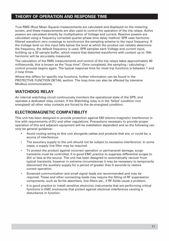
Configuring the User Screen
The default screen can be configured asa user screen, where the four line displaycan be customised to indicate fourmeasurement values of a possible 37electrical system measurements. Thisfeature is accessed via the Configurationmenu.
Press Enter on start editing theindividual display lines.
Use the Up/Down keys to scroll throughthe available parameters, and pressEnter to make the selection. Thefollowing measurements are availablefor display:
None, VL1, VL2, VL3, I1, I2, I3, W1, W2,W3, VA1, VA2, VA3, VAr1, VAr2, VAr3,PF1, PF2, PF3, PA1, PA2, PA3, Vavg, Iavg,Isum, Wsum, VAsum, VArsum, PFsum,PAsum, Freq, VL1L2, VL2L3, VL3L1, In,Freq2, Angle, Ig
Scroll Down to view or edit the settingsfor Line 4.

Viewing the User Screen
Select the Power Metering screen and choose the User Screen option. The customised screenwill be displayed until the one-minute timeout restores the default screen again. If a permanentuser screen display is required, you can make it the default screen as follows: With the UserScreen displayed, press and hold the Up and Down buttons. After 5 seconds, the display willflash to confirm that the default has been changed.
To cancel the user screen and change the default display back to the Relay Status display, eithera) re-configure all four parameters to NONE, or b) select the Relay Status screen then press andhold the Up and Down buttons until the display flashes.
If the user screen has been configured,you can select it from the Power Meteringmenu.
21

Saving Relay Setup
When changes have been made to any parameter in the configuration menu, the save commandmust be used to permanently store the new settings.
If changes have not been saved, they willbe lost when the product is powereddown. Press ENTER to select the Savecommand.
Press ENTER again, and you will beprompted with SURE?. If you are sureyou wish to save the changes, pressENTER again, otherwise, press ESC tocancel the save operation.
Event Log Menu
Every time a relay trips, event details can be recorded in the event log with a time and datestamp. This is useful for analysing the system problems, and because events are recorded to atime resolution of 100ms, the sequence of trip events can be studied. The date and time aremaintained by an internal real time clock with battery backup. The product stores details of thelast fifty trip events, and if more trips occur, the oldest records are deleted so that newinformation can be recorded.
IMPORTANT: Event information will belost if the product is powered down. Theevent log will also be cleared if the relayconfiguration has been altered in theconfiguration menu.
The most recent trip is held in the highestevent record. In this example, Relay 1tripped on March 14, 2004 at 10:22 am,because of an under voltage condition.You can view the trip settings using theUP/DOWN keys, but no changes can bemade. To view the other eventinformation, press ENTER to edit theevent number, then use the UP/DOWNkeys to step through them.If no trip events have taken place sincethe last power-down, you will find blankrecords.
22

23
SYSTEM CONFIGURATION AND RELAY STATUS
When the SPR is initially installed, the relay status will display a blank screen since system hasnot been configured for your application and the relay parameters have not been set up. Relayparameter settings will depend upon your configuration.
System configuration
All aspects of product operation are defined from this configuration menu. Certain commandscan be locked by password, and be hidden. In some cases, the configuration menu is not evenavailable. The system configuration parameters consist of
● System Voltage● System Current (Amps)● System Type
To check your system configuration, proceed as follows:
Return to the Main Menu by pressingESC as required.Use the DOWN key to highlight POWERMETERING and press ENTER.
Use the DOWN button to highlightSYSTEM CONFIG and press ENTER. Thesystem configuration display will appearon the screen
The Primary System Voltage and PrimarySystem Current (Amps) can be set to suityour usage; System Power is calculatedaccording to these values.The System Type is factory pre-set to 3-phase 3 wire or 4 wire, and can not bechanged.

Default settings are the factory buildvoltage and current for the product. Ifconnections are via P.T. or C.T. then youwill need to change the system settings. Proceed as follows:Return to the Main Menu by pressingESC as required.Use the DOWN key to highlightCONFIGURATION and press ENTER.Use the DOWN key to highlight RANGEand press ENTER.The range display will appear on thescreen
Position the first parameter under theflashing cursor using the UP/DOWNkeys. Press ENTER to select theparameter value and amend the valueusing the UP/DOWN keys.Press ENTER if the value is correct, orESC if an error has been made, andchange the other parameter if necessary.
Range changes take effect as they areentered and do not need to be savedexplicitly.
Press ESC to return to the main menu.
Bus Readings
If connected, check that the frequency iscorrect.
24

25
Relay status
When the SPR is initially installed, the trip function (parameter to be monitored) of each relayhas not been set, and the display will be blank. The number of, and the setting for each, relays isdependent upon your requirement, up to a maximum of 12 relays.Each relay can be set to monitor any one of 27 protective (electrical and logical) trip functions;these are listed in Table 1. (The ANSI Number refers to the American National StandardsInstitute listing).
Table 1 Relay Protective Trip Functions
ANSI Type No Menu Description Description
Unused The relay is disabled59 Over Volts Over Voltage Relay27 Under Volts Under Voltage Relay
81O Over Freq Over Frequency Relay81U Under Freq Under Frequency Relay50 Over Amps Instantaneous Over Current Relay37 Under Amps Instantaneous Under Current Relay
50N Over Amps Instantaneous Over Neutral Current Relay32R Reverse Pwr Reverse Power Relay32O Over Power Forward Power Relay40Q Reverse VAr Reverse VAr Relay47 UnBal Volts Unbalanced Voltage Relay46 UnBal Amps Unbalanced Current Relay
51V I/T+V.R. Time Over Current with Voltage Restraint Relay51 I/T Time Over Current Relay
51G Gnd Fault Neutral Ground Fault Relay25 Sync Synchronism Check Relay
25D Sync+DB Synchronism Check with Dead Bus Relay47 Phase Order Phase Sequence Relay
Logical AND Will trip if all 3 inputs are trippedLogical OR Will trip if any input is trippedLogical NAND Will trip unless all 3 inputs are trippedLogical NOR Will trip if any input is not trippedLogical XOR Will trip if the 3 inputs are not in the same stateLogical Vote Will trip if at least 2 inputs are trippedLogical Disc Will trip if there is a discrepancy between inputs Alarm Will trip if an alarm situation existsUnack Alarm Will trip if an alarm has not been acknowledged
Note: Although the number of physical relays will be 8 or 12, the SPR will allow you to set up to16. These ‘virtual’ relays operate normally, although there is no physical relay contact. Thesecan typically be used for marshalling purposes.

26
RELAY PROTECTIVE TRIP FUNCTIONS
General
This section gives details on the setting of Relays in general, followed by some applicationexamples.
At the initial Screen, scroll down toCONFIGURATION. Press ENTER to bringup the menu shown opposite.
Press ENTER to bring up the Relayparameters, opposite.(The parameters shown are for exampleonly).
To change the Relay number, pressEnter and the cursor will move to thenumber. Use the UP/DOWN keys toscroll to the required Relay number.
Press ENTER to accept or ESC to reject.Use the DOWN key to select TRIP andpress ENTER to highlight the parameterANSI number or function (cursor movesto the right).Use the UP/DOWN keys to scroll to therequired function; press ENTER toaccept or ESC to reject.
Each trip function has its own set ofparameters. Use the UP/DOWN keysscroll down and review or change theparameter settings as required.
Some parameters have YES / NOchoices, while others require numericalinput.
When all settings are correct, press ESConce to return to CONFIG or twice toreturn to the Main Menu.

27
RELAY SETTING EXAMPLES
To show how to configure the system and the relays, some examples are included here.
Setting up a relay contact
This example will demonstrate how toconfigure one relay contact inside theSPR to perform an over-voltage function.You will be setting Relay 1 to operate asOver Voltage, tripping at 120 Volts.
Switch on the auxiliary supply. The start-up screen (opposite) will be displayed for5 seconds.
The display then defaults to the RelayStatus Display, shown opposite.
Note: When no front panel switches havebeen pressed for 60 seconds, the displaywill revert to the Relay Status display.
If no Relay functions have been set, thisdisplay may be blank.
If necessary, set up the unit contrast (seeLCD contrast control).
Press the ESC key to bring up the MainMenu.
Using the DOWN key, scroll untilCONFIGURATION is under the cursor.
Press ENTER and the configurationscreen will be displayed.

Press ENTER to bring up the Relay set-up screen.
If Relay 1 is not displayed, press ENTERto move the cursor to select the relaynumber; the relay selected can bechanged using the UP/DOWN keys.When 1 is displayed, press ENTER to accept.
The function required for this example isunder voltage (UNDER VOLTS). Movethe cursor onto the Trip line and pressENTER.Use the UP/DOWN keys to select theUNDER VOLTS function. (The ANSInumber will also be displayed in thisexample, see Table 5).
When the correct function is displayed,press ENTER.
28

29
CAPTION SETTING FOR RELAY CONFIGURATION
By default, the caption is the ANSInumber or logical name for the selectedrelay function. If a different caption isrequired, you can edit the displayedcaption name to any 4-charactercombination to suit the application.
Scroll down to the ‘caption’ line
Press ‘Enter’ and the cursor will moveacross to the caption text field
Use the Up/Down arrow keys to changethe highlighted character. Permissiblecharacters are alphabetic, numeric orsymbol are:
{|} !“#$%&’()*+,-./:;<=>?@[]^_
0123456789
ABCDEFGHIJKLMNOPQRSTUVWXYZ
abcdefghijklmnopqrstuvwxyz
Press ‘Enter’ to select the next character
Continue to edit the remainingcharacters, until all four digits have been entered.

Logged
SPR can record the time date of tripevents. The configuration setting for eachrelay allows the ‘Logged’ selection to beset to Y (yes) or N (no). If Logging isenabled, then every trip event for thatrelay will be recorded in the log. Press‘Enter’ to select the Logged function,then use the Up/Down keys to changebetween Y and N.
Latched
The relay-latching feature can beswitched on or off as required. Whenenabled, and a trip condition is detected,the relay will change state and stay inthis condition until it is specifically reset.This is typically used to lock out furtheroperation of equipment after a fault hasbeen detected. Note that setting theLatched operation may be undesirable forsome trip functions. Press ‘Enter’ to selectthe Latched function, then use theUp/Down keys to change between Y andN.
Alarm
The alarm function, when enabled, willcause the LCD display to flash (to attractattention) when the relay trips. Even ifthe relay is reset (when the trip conditiongoes away) the display will continue toflash. The alarm must be acknowledgedby pressing a key. Press ‘Enter’ to selectthe Alarm function, then use theUp/Down keys to change between Y andN. This topic is covered in more detailwithin the examples section.
30

31
Fail Safe
The default relay operation is failsafe,meaning the relay contact is energised inthe ‘normal’ condition and de-energisedin the ‘tripped’ condition. Setting Failsafeto ‘N’ will change the default relay stateto de-energised, so the relay will energizeon trip. Press ‘Enter’ to select the Failsafefunction, then use the Up/Down keys tochange between Y and N.
Select TripPoint and press ENTER. Thevalue displayed is in real units – in thiscase, AC Volts. Use the up/ down keys toadjust the trip voltage to 100. Whenfinished, press ENTER.
DIFF means differential or hysteresis.This is used to give stability to the relay,and to stop it from nuisance tripping.When the measured signal level is veryclose to the trip point, electrical noiseand spikes can lead to spuriousenergize/de-energize relay operationswhen the level momentarily exceeds thetrip point, then returns to its normallevel. The DIFF setting increases thethreshold between trip and reset pointsto add stability to noisy systems. Theparameter is a real unit – in this case, ACvolts. Set the value to 3 volts.
Note: Too little hysteresis may lead to nuisance tripping, whilst too much hysteresismay mean the relay will not drop back in after a trip. Hysteresis settings can causeproblems if set unnecessarily high. The default setting is 1% of the nominal range, butthis can be increased as required for ‘noisy’ signals.

Finally, the time delay can be set. Thenumber is adjustable between 0 and 30seconds in steps of 0.1 second. Use thearrow keys to change the value, andpress ENTER to accept. Set the value to 1second. The time delay is a qualificationperiod for a trip condition. The tripcondition must exist for the entireduration of the delay before the relay willchange state.
Now the relay setup is complete. PressESC once to quit the relay setup menuand return to the Configuration menu.
To save the configuration changes forfuture use, scroll down the Configurationmenu and select the SAVE RELAYSETTINGS option and press ENTER. Thesettings will be stored in non-volatilememory, and will be automaticallyrecalled every time the product isswitched on.
Press ESC three (3) times to return to theMain Menu.
Press ENTER to view the Relay StatusDisplay.
Summary of the new relay settings
You should now have set the product asfollows:
Relay 1
Trip Under Volts 27
Caption 27
Logged N
Latched N
Alarm N
Failsafe Y
TripPoint 100.0 V
Diff 3.0 V
TimeDelay 1.0 Sec
32

33
Testing Relay 1
Now you are ready to test the relaycontact function. This example assumesa nominal 120V product.
With no measuring signal input, the relayshould be tripped (no Voltage ). Confirmthat Relay 1 contact is de-energised.
Apply a three-phase, variable, AC voltagesource to the input, initially set to 120V.Now decrease the voltage slowly.Confirm Relay 1 contact is energised.
Note that the SPR is checking each phasefor a voltage less than 100 V.
Once the voltage falls below 100 V, therelay will trip, and the status display willindicate as shown opposite.
The # symbol indicates that Relay 1 hastripped (and is still tripped).
Confirm that Relay 1 contact is now de-energised.
Now increase the voltage until the # signdisappears. This should be a level of 103V (which is the trip setting of 100 V plusthe differential of 3 V)
The relay will change state, back toenergised.

Setting up an Alarm
This example will demonstrate how to configure relay contacts inside the SPR to cause an alarmcondition when a trip is detected. You will be setting Relay 1 to operate as Over Voltage,tripping at 120 V (this follows on from the previous example, Setting up a relay contact).
Start from the Relay Status Displayshown.
Press the ESC button to bring up theMain Menu. A flashing cursor will appearon the active line.
Using the DOWN key, scroll untilCONFIGURATION is under the cursor.
Press ENTER and the configurationscreen will be displayed.
Press ENTER to bring up the relay setupscreen.
34

35
If Relay 1 is not displayed (it coulddefault to another relay), press ENTER tomove the cursor to select the relaynumber; the relay selected can bechanged using the UP/DOWN keys.When 1 is displayed, press ENTER toaccept.Then change the trip function to Over
Volts.
Using the UP/DOWN keys, scroll downuntil Alarm is under the cursor, thenpress ENTER. Change the function to Y(Yes) using the UP key. Then change thetrip point to 120V. Change the Diffsetting to 3.0V and delay to 1.0 seconds.
Now the relay setup is complete. PressESC once to quit the relay setup menuand return to the Configuration menu.
To save the configuration changes, scrolldown the Configuration menu and selectthe SAVE option and press ENTER. Thesettings will be stored in non-volatilememory, and will be automaticallyrecalled every time the product isswitched on.Press ESC three (3) times to return to theMain Menu.
Press ENTER to view the Relay StatusDisplay.

Summary of the new relay settings
You should now have set the product as follows:
Relay 1
Trip Over Volts 59
Caption 59
Logged N
Latched N
Alarm Y
Failsafe Y
TripPoint 120.0
Diff 3.0 V
TimeDelay 1.0 Sec
Testing Relay 1
Now you are ready to test the relay Alarm function.With no measuring signal input, the relay should not be tripped. Confirm that Relay 1 contact isenergised (Failsafe)Apply a variable AC voltage source to the input, and slowly increase the voltage.Note that the SPR is checking each phase for a voltage greater than 120 V.Once the voltage exceeds 120 V, therelay will trip, and, because the alarmfunction is enabled on Relay 1, the LCDbacklight will flash on and off to attractattention.The * symbol indicates that Relay 1caused the alarm condition.
Now decrease the voltage below 117 V.The relay contacts will reset, but thedisplay will continue to flash. You mustacknowledge the alarm to stop thedisplay flashing, by pressing the Enter button.
36

37
Increase the voltage source again untilthe relay trips. The display will start toflash. Now press Enter to acknowledgethe alarm. The display indicates that youhave acknowledged the condition, butcontinues to flash slowly to indicate therelay is still in the tripped condition. The+ symbol also indicates this.
Now decrease the voltage below 117 V.The relay contacts will reset, the statusdisplay will clear, and the display willstop flashing.
Note on Alarms: You can set up arelay contact to trip if any relay hascaused an alarm condition. This can beused as a common alarm signal, or usedto control an external sounder (horn)etc. Additionally, a relay can beconfigured to trip only if the alarm hasnot been acknowledged.

Latching a Relay
This example demonstrates Relay 1 latching when a trip is detected. Relay 1 is configured toOver Voltage, tripping at 120 V (from the examples Setting up a relay contact and Setting up anAlarm).
Start from the Relay Status displayshown.
Press the ESC button to bring up theMain Menu, a flashing cursor will appearon the active line.
Using the DOWN key, scroll untilCONFIGURATION is under the cursor.
Press ENTER and the configurationscreen will be displayed.
38

39
Press ENTER to bring up the relay setupscreen.
If Relay 1 is not displayed, press ENTERto move the cursor to select the relaynumber; the relay selected can bechanged using the UP/DOWN keys.When 1 is displayed, press ENTER toaccept.
Using the UP/DOWN buttons, scrolldown until Latch is under the cursor,then press ENTER. Change the functionto Y (Yes) using the UP button.
Switch the Alarm function off.
Now the relay setup is complete. PressESC once to quit the relay setup menuand return to the Configuration menu.
To save the configuration changes forfuture use, scroll down the Configurationmenu and select the SAVE option andpress ENTER. The settings will be storedin non-volatile memory, and will beautomatically recalled every time theproduct is switched on.

Press ESC three (3) times to return to theMain Menu.
Press ENTER to view the Relay StatusDisplay.
Summary of the new relay settings
You should now have set the product as follows:
Relay 1
Trip Over Volts 59
Caption 59
Latched Y
Alarm N
Failsafe Y
TripPoint 120.0
Diff 3.0 V
TimeDelay 1.0 Sec
40

41
Testing Relay 1 Latch function
Now you are ready to test the relay Latchfunction.
With no measuring signal input, the relayshould not be tripped. Confirm that Relay1 contact is energised (because we setFail Safe to Y).
Apply a variable AC voltage source tothe input, and slowly increase thevoltage.
Note that the SPR is checking each phasefor a voltage greater than 120 V.
Once the voltage exceeds 120 V, therelay will trip, and the relay statusdisplay will indicate as shown.
The # symbol indicates that Relay 1 hastripped (and is still tripped).
Confirm that Relay 1 contact is now de-energised.
Now decrease the voltage below 117 V.The # remains on the display, and thecontacts stay de-energised. The relay haslatched and must be manually reset.
Press the ESC button to bring up themain menu.
Select the RESET TRIPS option and pressENTER.

Line 1 shows allows you to select theappropriate relay. Press ENTER and usethe up/down arrow keys to select adifferent relay, and press ENTER toselect it.
The second line of the display showsthe function assigned to each relay. Thisis for information only, and cannot bechanged. Line 4 indicates that the relayis tripped.
Press the DOWN key to place the cursorover Tripped.
Press ENTER, edit the trip flag to N (NO)using the DOWN key, then press ENTERto accept the change.
The relay is now reset.
Confirm that Relay 1 contact is nowenergised
Exit the Reset Menu by pressing ESC,and go back into the Relay Statusscreen.
The asterisk has disappeared.
Note:
If the trip condition still exists, thelatched relay cannot be reset.
42

Event Log
SPR can record the time date of trip events. The configuration setting for each relay allows the‘Logged’ selection to be set to yes or no. If Logging is enabled, then every trip event will berecorded.
Edit relay 1 settings as follows, changing Logged to Y and Latched to N.
Relay 1Trip Over Volts 59Caption 59Logged YLatched NAlarm NFailsafe YTripPoint 120.0 VDiff 3.0 VTimeDelay 1.0 Sec
Apply a variable AC voltage source to the input, and increase the voltage until the relay trips.The status display will indicate 59# as normal. Now reduce the voltage until the relay resets.Wait several seconds, then increase the voltage to cause another trip. This exercise shouldhave made two entries into the event log.
The event log can be accessed from themain menu
Scroll down until the cursor highlightsthe event log entry.
Press ENTER to access the sub-menu.There are three entries. Select ‘VIEW.’
43

The event log contains data for up to50 trip events, stored in time order,oldest first. The event record indicatesthe date and time of the trip, the relaynumber, and the trip function type.You can scroll down to review therelay settings.
To view other events, select the eventnumber and use the Up/Down arrowsto scroll through the event log entries.
Press ESCAPE to quit the VIEW menu.Select SUMMARY and press ENTER.The event log summary is displayed.Use the Up/Down arrows to scrollthrough the summary information foreach log entry.
To clear the event log, select theCLEAR menu and press ENTER.
The confirmation screen preventsaccidental deletion of the log. PressENTER to confirm the clear operation,or press ESCAPE to quit.
Note: The event log data is stored onlywhilst the auxiliary supply is present.
Note: The event log stores the mostrecent 50 trip events. If more than 50events are logged, the older entries aredeleted.
44

45
Logical operators
This example demonstrates how the logical operators can be used. You will be setting up Relay2 to trip at the same time as Relay 1 trips, effectively making a double-pole relay. Relay 1 isconfigured to Over Voltage, tripping at 120 Volts.
Start from the Relay Status screen.
Press ESC to bring up the Main Menu Aflashing cursor will appear on the activeline.
Using the DOWN key, scroll untilCONFIGURATION is under the cursor.
Press ENTER and the configurationscreen will be displayed.
Press ENTER again to bring up the relaysetup screen.
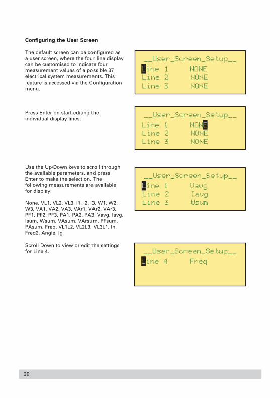
If Relay 2 is not displayed, press ENTERto move the cursor to select the relaynumber; the relay selected can bechanged using the UP/DOWN buttons.When 2 is displayed, press ENTER toaccept.
The function we require for Relay 2 inthis example is Logical OR. Move thecursor onto the Trip line and pressENTER.
Press the UP/DOWN KEY until LOGICALOR appears, then press ENTER to acceptit. Latch, Alarm and Inverted functionswork in the same way as other relays.You now need to specify the input datafor the logical operation. The input datawill be the status of other relays in thesystem. Scroll the menu down to Input 1.Press ENTER to select Input 1, and youcan now enter the relay number whichwill control the function. In this example,the data will be the status of relay 1(Over Volts function).
Use the UP KEY to set the value to 1,then press ENTER.
Now the relay setup is complete.
Press ESC to quit the Relay Setup menuand return to the Configuration menu.
To save the configuration changes, scrolldown the Configuration menu and selectthe SAVE option and press ENTER
46

47
To save the configuration changes, scrolldown the Configuration menu, select theSAVE option and press ENTER. Thesettings will be stored in non-volatilememory, and will be automaticallyrecalled every time the product isswitched on.
Press ESC three (3) times to return to theMain Menu.Press ENTER to view the Relay StatusDisplay.
Summary of the new relay settings
You should now have set the product as follows:
Relay 2
Trip Logical OR
Caption OR
Logged N
Latched N
Alarm N
Failsafe Y
Input 1 1
Input 0 0
Input 0 0
Delay On 0.0 sec
Delay Off 0.0 sec

Testing the function of Relay 2
Now you are ready to test the ORfunction for Relay 2, using Relay 1 whichis configured to monitor Over Voltage.
With no measuring signal input, the relayshould not be tripped.
Apply a variable AC voltage source to theinput, and slowly increase the voltage.Once the voltage exceeds 120 V, Relay 1will trip. Because of the OR function,Relay 2 should trip at the same time.
The Relay Status display will be asshown opposite.
The # symbol indicates that Relays 1 and2 have tripped.
Now decrease the voltage below 118 V.Both gate symbols now disappear.Using the OR function has created adouble-pole relay – the most simpleapplication of logical operators. Thereare other logical operators and, since thefunction has three inputs, this is a verypowerful feature.
Other operators (3 input) are:
AND Will only trip if ALL input relays are tripped.
NAND Will NOT trip if one or two input relays are tripped.
Conversely, WILL trip if ALL input relays are NOT tripped.
OR Will trip if ANY of the input relays are tripped.
NOR Will NOT trip if any of the input relays are tripped.
XOR Will only trip if the input relays are DIFFERENT from each other.
VOTE Will trip if the majority of the inputs relays are tripped.
DISC Will trip if there is a discrepancy among the inputs relays.
48

49
Time Over current Relay
The SPR offers good accuracy of setting and high repeatability when compared to rotating disctype electromechanical relays. This relay can be used for selective short circuit protection andoverload protection. Better accuracy means that fault grading intervals are reduced, improvingthe response speed of a co-ordinated protection system.The time over current functions have an IDMT (Inverse Definite Minimum Time) response, whichmeans that the relay operating time tends towards a minimum value with increasing values ofcurrent.
Example of Relay setting:Nominal System Current = 200 AmpsThe Measuring or Protection CT Ratio = 250:5 Amps
Maximum System Fault Current = 1000 AmpsFault Current into the SPR = 1000 x 5 = 20A
250Current multiple = 1000 A = 5x
200 AThe tripping time, in this example, needs to be 2.4 seconds for proper system fault co-ordination, based on the standard inverse time curve.
Using the graph (see Fig 4, page 59), cross reference the desired time of 2.4 seconds (the Y-axis)against the current multiple of 5x (the X-axis). The time dial setting needs to be approximately 5.An exact setting can be calculated using the formulae given in the Time Over CurrentCharacteristics, in the Protective Function Detail section. The formulae has been transposed togive the time dial setting:
(time – k3) x (Multiplek2 - 1) = Time Dial Settingk1
For standard inverse curve, k1 = 0.01414, k2 = 0.02, k3 = 0.1
(2.4 seconds – 0.1) x (50.02 - 1) = 5.3 Time Dial Setting0.01414
Having calculated the settings, now configure Relay 3 to be a time over current relay, with theparameters set as follows:
Relay 3
Trip I/T 51Caption 51Logged NLatched NAlarm NFailsafe YTripPoint 200A (assuming that CT ratio has been set, otherwise 4A)TimeCurve 1TimeDial 5.3 Sec

Testing the function of Relay 3
With no measuring signal input, relay 3should not be tripped.
Connect a 20 Amp AC constant currentsource through any phase. Switch on thecurrent, and start a timer. After 2.4seconds, the relay will trip, and the 51# symbol will appear in the relay status display.
If the current source is not constant, thetrip time will be continuously re-calculated by SPR, and will vary inproportion to that current.If precision timing equipment is notavailable, try injecting a smalleroverload, for example 8 Amps (which is2x the setpoint) When the time dialsetting is set to approximately 10seconds, the trip time will be tenseconds. (calculation gives ideal time dialsetting of 9.8 for a 10 second trip time)
50

51
PROTECTIVE FUNCTION DETAIL
The Relay Protective Trip Functions are detailed in Table 1 (shown again here for convenience).
Table 1 Relay Protective Trip Functions
ANSI Type No Menu Description Description
Unused The relay is disabled59 Over Volts Over Voltage Relay27 Under Volts Under Voltage Relay
81O Over Freq Over Frequency Relay81U Under Freq Under Frequency Relay50 Over Amps Instantaneous Over Current Relay37 Under Amps Instantaneous Under Current Relay
50N Over Amps Instantaneous Over Neutral Current Relay32R Reverse Pwr Reverse Power Relay32O Over Power Forward Power Relay40Q Reverse VAr Reverse VAr Relay47 UnBal Volts Unbalanced Voltage Relay46 UnBal Amps Unbalanced Current Relay
51V I/T+V.R. Time Over Current with Voltage Restraint Relay51 I/T Time Over Current Relay
51G Gnd Fault Neutral Ground Fault Relay25 Sync Synchronism Check Relay
25D Sync+DB Synchronism Check with Dead Bus Relay47 Phase Order Phase Sequence Relay
Logical AND Will trip if all 3 inputs are trippedLogical OR Will trip if any input is trippedLogical NAND Will trip unless all 3 inputs are trippedLogical NOR Will trip if any input is not trippedLogical XOR Will trip if the 3 inputs are not in the same stateLogical Vote Will trip if at least 2 inputs are trippedLogical Disc Will trip if there is a discrepancy between inputs Alarm Will trip if an alarm situation existsUnack Alarm Will trip if an alarm has not been acknowledged
Accuracy levels and resolution of trip settings are detailed in ACCURACY AND RESOLUTION(located in the product specification section) unless otherwise stated.

TYPE 25 — SYNCHRONISING/SYNCHRONISM-CHECK
This function operates as a permissive relay, where the ‘not tripped’ condition indicates that thetwo systems are within the permitted limits to allow synchronism. A ‘tripped’ condition indicatesthat the systems are not within the allowable limits, and synchronism is not possible.
The status display will indicate 25# (relay is tripped) when the relay is not in synchronism. Thedisplay indication will disappear when synchronism is achieved.
When failsafe is set to ‘yes’, the relay contacts will energize when the GEN and BUS circuits arein synchronism. An out-of-sync condition, or loss of auxiliary supply, will de-energize the relaycontacts.
Brief details
The permissive relay operates when the “Bus” and “Generator” signals are within the selectedlimits of frequency, phase angle, voltage and the phase sequence of the “Generator” voltageinputs are correct for the duration of the selected delay to permit or to cause the paralleling oftwo circuits. The relay will return to the “tripped” condition when any one of the conditionsdetailed above become invalid. The time delay is used on the transition to the “not tripped”condition.
Parameters
You must specify the following parameters for operation of the synchronising relay:● The maximum permitted phase angle between the “Bus” input voltage and the
reference “Generator” voltage (V1, VA, or V1-2),● The maximum permitted voltage difference between the “Bus” input voltage and the
reference “generator” voltage,● The maximum permitted frequency difference between the “Bus” and “Generator”
(slip frequency)● The qualifying time for which these conditions must be true
• The minimum voltage level below when function is disabled.
Parameter details
Range of Phase Difference (PhAngle) 2 — 20 degrees
Range of Voltage Difference (VDelta) 0 — 20% of nominal input voltage
Range of minimum Voltage level (Vmin)5- 119% of nominal input voltage
Range of Time Delay (TimeDelay) 0 to 5 seconds
Range of slip frequency (SlipFreq) 0.1 — 1 Hz
Voltage Accuracy ± 2% of nominal input voltage
Resolution of slip frequency 0.1 Hz
Frequency Accuracy ± 0.1 Hz
52

There is a relationship between the phase angle and the slip frequency settings. When oneparameter is adjusted, the setting range of the other may be automatically adjusted to prevent acondition where the relay may never close.
CAUTION: This trip relay can be configured to Latch. This feature may be
undesirable, if enabled in error.
TYPE 25D — SYNCHRONISING/SYNCHRONISM-CHECK WITH DEAD BUS
This function operates as a permissive relay, where the ‘not tripped’ condition indicates that thetwo systems are within the permitted limits to allow synchronism. A ‘tripped’ condition indicatesthat the systems are not within the allowable limits, and synchronism is not possible.
The status display will indicate 25D# (relay is tripped) when the relay is not in synchronism. Thedisplay indication will disappear when synchronism is achieved, or when the BUS voltage isbelow the ‘Deadbus’ setting.
When failsafe is set to ‘yes’, the relay contacts will energize when the GEN and BUS circuits arein synchronism. An out-of-sync condition, or loss of auxiliary supply, will de-energize the relaycontacts.
Brief details
The relay either:(a) operates when the “Bus” and “Generator” signals are within the selected limits of
frequency, phase angle, voltage and the phase sequence of the “Generator” voltage inputs is correct for the duration of the selected delay
or:(b) the voltage on the “Bus” voltage input is below the selected limit and the phase
sequence of the “Generator” voltage inputs is correct for the duration of the selected delay to permit or to cause the paralleling of two circuits. The relay will return to the “tripped” condition when any one of the conditions detailed above become invalid. The time delay is used on the transition to the “not tripped” condition.
Parameters
You must specify the following parameters for operation of the synchronising relay:● The maximum permitted phase angle between the “Bus” input voltage and the
reference “Generator” voltage (V1, VA, or V1-2),● The maximum permitted voltage difference between the “Bus” input voltage and the
reference “generator” voltage,● The maximum permitted frequency difference between the “Bus” and “Generator”
(slip frequency)● The maximum voltage that may be present on the “Bus” voltage input before the phase,
frequency and voltage difference conditions are required to qualify the trip condition (forlevels below this voltage the relay will operate providing that the phase sequence of the “Generator” voltage inputs is correct).
● The time for which these conditions must be true
• The minimum voltage level, below which they function.
53

Parameter details
Range of Phase Difference (PhAngle) 2 — 20 degrees
Range of Voltage Difference (VDelta) 0 — 20% of nominal input voltage
Minumum Voltage Level (Vmin) 5-119% of nominal input voltage
Range of Bus Voltage Trip point 5 — 50% of nominal input
Range of Time Delay (TimeDelay) 0 to 5 seconds
Range of slip frequency (SlipFreq) 0.1 — 1 Hz
Voltage Accuracy ± 2% of nominal input voltage
There is a relationship between the phase angle and the slip frequency settings. When oneparameter is adjusted, the setting range of the other may be automatically adjusted to prevent acondition where the relay may never close.
CAUTION: This trip relay can be configured to Latch. This feature may be
undesirable, if enabled in error.
TYPE 27 — UNDER VOLTAGE
Brief details
The relay will operate (trip) when the signal level on any of the “generator” voltage inputs isless than the selected value for the duration of the time delay. The relay will return to the “nottripped” condition (provided that latched operation has not been selected) when all “generator”voltage inputs rise above the selected trip point by at least the hysteresis value. The time delayis not used on the transition to the “not tripped” condition.
Parameters
You must specify the following parameters for operation of the under voltage relay:● The minimum permitted voltage on any of the voltage inputs from the “generator”.● The time for which the under voltage conditions must be true.● The voltage above the previously defined minimum that all inputs from the “generator”
must exceed to return operation to the not tripped condition following a trip. (Hysteresis)
Range of Voltage Trip point (Trip Point) 5-119% of nominal input
Range of Diff (Diff) 1 — 15% of nominal input
Range of Time Delay (TimeDelay) 0 to 30 seconds
54

55
TYPE 47 — PHASE ORDER (PHASE SEQUENCE)
Brief details
This relay will operate when the instantaneous levels on the voltage input to Phase B (2) is notpositive or the instantaneous level on the voltage input to Phase C (3) is not negative whenmeasured at the zero crossing point on the rising edge of Phase A (1). The relay will return tothe “not tripped” condition (provided that latched operation has not been selected) when theinstantaneous levels on the voltage input to Phase B (2) is positive and the instantaneous levelon the voltage input to Phase C (3) is negative when measured at the zero crossing point on therising edge of Phase A (1). The time delay is not used on the transition to the “not tripped”condition.
This function is used to determine that the phase sequence of the voltage inputs is correct.
Parameters
You must specify the following parameters for operation of the reverse voltage relay:● The time for which the reverse phase voltage conditions must be true.
Parameter details
Range of Time Delay 0 to 30 seconds
TYPE 32R — DIRECTIONAL POWER (REVERSE)
Brief details
The relay will operate (trip) when the power level into the “generator” on any phase exceeds theselected value for the duration of the time delay. The relay will return to the “not tripped”condition (provided that latched operation has not been selected) when the power level into the“generator” on all phases falls below the selected trip point by at least the hysteresis value. Thetime delay is not used on the transition to the “not tripped” condition.
The function is intended to detect conditions such as generator motoring.
Parameters
You must specify the following parameters for operation of the directional power relay:● (SPR-014) The maximum permitted power on any phase into the “generator”.
• (SPR-013) The minimum permitted system power into the “generator”.● The time for which the directional power conditions must be true.● The power level below the previously defined maximum that all phases from the
“generator” must exceed to return operation to the not tripped condition following a trip. (Hysteresis)
Parameter details
Range of Directional Power trip (TripPoint) 3 — 120% of nominal power per phase (line)
Range of Diff (Diff) 1 — 15% of nominal power per phase
Range of Time Delay (TimeDelay) 0 to 30 seconds
Accuracy of Directional Power Trip point ± 3% of nominal input

TYPE 47 — VOLTAGE UNBALANCE
Brief details
The relay will operate (trip) when the difference in signal level on any of the “generator” voltageinputs voltage is greater than the selected value for the duration of the time delay. The relay willreturn to the “not tripped” condition (provided that latched operation has not been selected)when the difference between all “generator” voltage inputs fall below the selected trip point byat least the hysteresis value. The time delay is not used on the transition to the “not tripped”condition.
Parameters
You must specify the following parameters for operation of the voltage balance relay:● The maximum permitted voltage difference between any of the voltage inputs
from the “generator”.● The time for which the voltage balance conditions must be true.● The voltage decrease below the previously defined maximum difference that all inputs
from the “generator” must be below to return operation to the not tripped condition following a trip. (Hysteresis)
Parameter details
Range of Voltage (Trip Point) 1 — 25% of nominal input
Range of Diff (Diff) 1 — 15% of nominal input
Range of Time Delay (Time Delay) 0 to 30 seconds
56

57
TYPE 51 — AC TIME OVER CURRENT
Brief details
The relay will operate (trip) when the signal level on any of the “generator” current inputs isgreater than the selected value. The response time of the relay will be a function of how farabove the selected value the current value is. The relay will return to the “not tripped”condition (provided that latched operation has not been selected) when all “generator” currentinputs fall below the selected trip.
Parameters
You must specify the following parameters for operation of the time over current relay:● The maximum permitted current on any of the current inputs from the “generator”.● The required time characteristic (digit identifying the level VS time curve required).● The “Time Dial Setting”.
Parameter details
Range of Current Trip point (Trip Point) 5 — 120% of nominal input
Time Curve (Time Curve) 1 (Standard Inverse)2 (Very Inverse)3 (Extremely Inverse)
Time Dial Setting Range (Time Dial) 0.1 to 9.9
Time Dial Setting Resolution 0.1
Resolution of curve timebase 100 milliseconds
Accuracy of timing (relative to the ± 5% of ideal + 2 loop times characteristics described below)
Maximum Input current for which 25 Amps for 5 Amp nominal unitTime-Current characteristics are valid 5 Amps for 1 Amp nominal unit
Response Time NOTE: The time-over current function involves many calculations, which are computationally intensive.
Worst case example: With all 12 relays defined as time-over current trips, the product loop time can be up to 150ms.
Note: Measurement accuracy should also be considered when operating at very small overcurrent levels since the slope of the curve could introduce additional timing errors.

Time over current characteristics
The response time of the relay when operating in Time Over Current mode may determinedusing the relationship:
The curves describing these characteristics may be found on the following pages (Figs 4 to 7).
Limits of operation
The maximum “Multiple of trip setting” applicable for a trip setting at “nominal input” (e.g. Trippoint at 5 Amps on a 5 Amp unit) is 5. “Multiple of trip setting” values of greater than 5 are onlyvalid for trip levels of less than “nominal input”. This parameter is limited by the dynamic rangeof the current input circuits which start to limit above 5 times “nominal” input.
The maximum time delay introduced by the Time-Current characteristics is limited by theresolution of the current input in the region of the trip point. This limits the “Multiple of tripsetting” to approximately 1.007.
58
Time-Current Characteristic k1 k2 k3
Standard Inverse 0.01414 0.02 0.1
Very Inverse 1.3636 1 0.1
Extremely Inverse 8.0808 2 0.1
Long time standby Earth Fault 12.121 1 0.1

59
Fig 4 Time - current characteristics - Standard Inverse (Time Curve =1)

Fig 5 Time - current characteristics - Very Inverse (Time Curve = 2)
60

61
Fig 6 Time - current characteristics - Extremely Inverse (Time Curve = 3)

TYPE 51V — AC TIME OVER CURRENT WITH VOLTAGE RESTRAINT
Brief details
The relay will operate (trip) when the signal level on any of the “generator” current inputs isgreater than the “modified” (see note below) selected value. The response time of the relay willbe a function of how far above the selected value the current value is. The relay will return tothe “not tripped” condition (provided that latched operation has not been selected) when all“generator” current inputs fall below the “modified” selected trip point.
Note: The maximum permitted current value used internally will be modified by the level of thecorresponding voltage input according to the “voltage restraint characteristic” defined below.
Parameters
You must specify the following parameters for operation of the time over current with voltagerestraint:
● The maximum permitted current on any of the current inputs from the “generator”.● The required time characteristic (character identifying the level VS time curve required).● The “Time Dial Setting”.
The “Rated” Voltage, (The 100% reference level used to calculate the “Restraint Voltage in thechart above).
62

63
Parameter details
Range of Current Trip point 5 — 120% of nominal input
Range of Rated Voltage Trip point 80 — 120% of nominal input
Range of Time-Current Characteristic Curves (Time Curve)
1 Standard Inverse
2 Very Inverse
3 Extremely Inverse
Time Dial Setting Range 0.1 to 9.9
Time Dial Setting Resolution 0.1
Resolution of curve timebase 100 milliseconds
Accuracy of timing (relative to the ± 5% of ideal + 2 loop timescharacteristics described below)
Maximum Input current for which 25 Amps for 5 Amp nominal unit Time-Current characteristics are valid 5 Amps for 1 Amp nominal unit
TYPE 51G — TIME OVER CURRENT NEUTRAL GROUND FAULT CHECK
Brief details
This trip has different implementations on models SPR-013 and SPR-014, as follows:
SPR-014 (3 phase 4-wire systems with neutral CT): The fault current is calculated as thedifference between the vector sum of the three phase current inputs and the neutral currentinput.
SPR-013 (3 phase 3-wire systems): The fault current is the vector sum of the three phase currentinputs only. Do not connect any signal to the Neutral current input terminals.
IMPORTANT: Ground fault current is not directly measured. This parameter is derived
by calculation. This unit has not been tested to UL 1053. The trip function is intended
for monitoring purposes only.
Parameters
You must specify the following parameters for operation of the neutral ground fault relay:● The maximum permitted value of the RMS of the vector sum of phase current inputs
and the neutral current input from the “generator”.● The “Time Dial Setting”.

64
Fig 7 Time - current characteristics - Long time standby Earth Fault

Parameter details
Range of Neutral Ground Fault 5 — 120% of nominal inputTrip point (TripPoint)Accuracy of Neutral Ground Fault ± 3% of nominal inputTrip pointTime-Current Characteristic (this Long time Standby Earth Faultcharacteristic is defined later in this document)Time Dial Setting Range 0.1 to 9.9Time Dial Setting Resolution 0.1Resolution of curve timebase 100 millisecondsAccuracy of timing (relative to the ± 5% of ideal +100 millisecondscharacteristics described in below)Maximum Input current for which 25 Amps for 5 Amp nominal unitTime-Current characteristics are valid 5 Amps for 1 Amp nominal unit
TYPE 59 — OVER VOLTAGE
Brief details
The relay will operate (trip) when the signal level on any of the “generator” voltage inputs isgreater than the selected value for the duration of the time delay. The relay will return to the“not tripped” condition (provided that latched operation has not been selected) when all“generator” voltage inputs fall below the selected trip point by at least the hysteresis value. Thetime delay is not used on the transition to the “not tripped” condition.
Parameters
You must specify the following parameters for operation of the over voltage relay:● The maximum permitted voltage on any of the voltage inputs from the “generator”.● The time for which the over voltage conditions must be true.● The voltage decrease below the previously defined maximum that all inputs from the
“generator” must be below to return operation to the not tripped condition following a trip. (Hysteresis)
Parameter details
Range of Voltage Trip point 5 — 120% of nominal inputRange of Time Delay 0 to 30 secondsRange of Diff 1 — 15% of nominal input
65

TYPE 81O — OVER FREQUENCY
Brief details
The relay will operate (trip) when the frequency of the “generator” input voltage is greater thanthe selected value for the duration of the time delay. The relay will return to the “not tripped”condition (provided that latched operation has not been selected) when the “generator” inputfrequency falls below the selected trip point by at least the hysteresis value. The time delay isnot used on the transition to the “not tripped” condition.
Parameters
You must specify the following parameters for operation of the over frequency relay:● The maximum permitted frequency input from the “generator”.● The time for which the over frequency condition must be true.● The frequency decrease below the previously defined maximum that the input from the
“generator” must exceed to return operation to the not tripped condition following a trip. (Hysteresis)
Parameter details
Range of Frequency Trip point (Trip Point) 40 — 70 Hz
Range of Diff (Diff) 0.1 — 10 Hz
Range of Time Delay (Time Delay) 0 to 30 seconds
NOTE: If the measured frequency exceeds the 70Hz working range, be aware
that the displayed frequency will be set to zero and the over frequency trip will
reset. If it is possible for the frequency in your application to exceed this upper
limit, ensure that under frequency trip is configured to pick up the zero
frequency value.
TYPE 81U — UNDER FREQUENCY
Brief details
The relay will operate (trip) when the frequency of the “generator” input voltage is less than theselected value for the duration of the time delay. The relay will return to the “not tripped”condition (provided that latched operation has not been selected) when the “generator” inputfrequency rises above the selected trip point by at least the hysteresis value. The time delay isnot used on the transition to the “not tripped” condition.
Parameters
You must specify the following parameters for operation of● The minimum permitted frequency input from the “generator”.● The time for which the under frequency condition must be true.● The frequency increase above the previously defined minimum that the input from the
“generator” must exceed to return operation to the not tripped condition following a trip. (Hysteresis)
66

67
Parameter details
Range of Frequency Trip point (Trip Point) 40 — 70 Hz
Range of Diff (Diff) 0.1 — 10 Hz
Range of Time Delay (Time Delay) 0 to 30 seconds
LOGICAL TRIP FUNCTIONS
Parameters
You must specify the following parameters for operation of the logical trip functions:● The logical function type● The trips (relay numbers) to be included in the logic function (up to three)● The time delay from the logical condition becoming true to the relay adopting the
“tripped” condition● The time delay from the logical condition becoming false to the relay returning to the
“not tripped” condition
Parameter details
Logic Functions Supported AND Output true when all inputs true
OR Output true when any input true
NAND Output true except when all inputs true
NOR Output true when no inputs are true
XOR Output true when odd number of inputs are
true
Vote Output true when the majority of inputs are
true
Disc Output true when inputs are different
Range of Delay to On Time 0 — 30 Seconds
Range of Delay to Off Time 0 — 30 Seconds

ANSI TYPE 40Q — REVERSE VAR
Brief details
The relay will operate (trip) when the VAr level into the “generator” on any phase exceeds theselected value for the duration of the time delay. The relay will return to the “not tripped”condition (provided that latched operation has not been selected) when the VAr level into the“generator” on all phases falls below the selected trip point by at least the hysteresis value. Thetime delay is not used on the transition to the “not tripped” condition.
The function is intended to detect conditions such as loss of field or loss of excitation.
Parameters
The following parameters must be specified for the operation of the reverse VAr reactive powerrelay:
● (SPR-014) The maximum permitted VAr on any phase into the “generator”.
• (SPR-013) The maximum permitted system VAr into the “generator.● The time for which the directional conditions must be true.● The VAr level below the previously defined maximum that all phases from the
“generator” must exceed to return operation to the not tripped condition following a trip. (Hysteresis)
Parameter details
Range of Reverse VAr trip (TripPoint) 3 — 120% of nominal VAr per phase (line)
Accuracy of Reverse VAr Trip point ± 4% of nominal input
Range of Hysteresis (Diff) 1 — 15% of nominal power per phase
Range of Time Delay (TimeDelay) 0 to 30 seconds
ANSI TYPE 50 — INSTANTANEOUS OVER CURRENT
Brief details
The relay will operate (trip) when the signal level on any of the “generator” current inputs isgreater than the selected value for the duration of the time delay. The relay will return to the“not tripped” condition (provided that latched operation has not been selected) when all“generator” current inputs fall below the selected trip point by at least the hysteresis value. Thetime delay is not used on the transition to the “not tripped” condition.
Parameters
The following parameters must be specified for the operation of the over current relay:● The maximum permitted current on any of the current inputs from the “generator”.● The time for which the over current conditions must be true.● The current decrease below the previously defined maximum that all inputs from the
“generator” must be below to return operation to the not tripped condition following a trip. (Hysteresis)
68

Parameter details
Range of Current Trip point (TripPoint) 30 — 300% of nominal input
Range of Hysteresis (Diff) 1 — 15% of nominal input
Range of Time Delay (TimeDelay) 0 to 30 seconds
Note: The time delay default setting is 0.2 seconds. This can be reduced in value if the trip pointis greater than 100%
ANSI TYPE 50N — INSTANTANEOUS OVER NEUTRAL CURRENT
Brief details
The relay will operate (trip) when the signal level on the “generator” neutral current input isgreater than the selected value for the duration of the time delay. The relay will return to the“not tripped” condition (provided that latched operation has not been selected) when the“generator” neutral current input falls below the selected trip point by at least the hysteresisvalue. The time delay is not used on the transition to the “not tripped” condition.
Parameters
The following parameters must be specified for the operation of the neutral over current relay:● The maximum permitted neutral current from the “generator”.● The time for which the over neutral current condition must be true.● The current decrease below the previously defined maximum neutral current that the “generator” must be below to return operation to the not tripped condition following a trip. (Hysteresis)
Parameter details
Range of Neutral Current Trip point (TripPoint) 30 — 300% of nominal input
Range of Hysteresis (Diff) 1 — 15% of nominal input
Range of Time Delay (TimeDelay) 0 to 30 seconds
Note: This trip is non-applicable on model SPR-013.
Note: The time delay default setting is 0.2 seconds. This can be reduced in value if the trip pointis greater than 100%
69

ANSI TYPE 37 — INSTANTANEOUS UNDER CURRENT
Brief details
The relay will operate (trip) when the signal level on any of the “generator” current inputs is lessthan the selected value for the duration of the time delay. The relay will return to the “nottripped” condition (provided that latched operation has not been selected) when all “generator”current inputs rise above the selected trip point by at least the hysteresis value. The time delayis not used on the transition to the “not tripped” condition.
Parameters
The following parameters must be specified for the operation of the under current relay:● The minimum permitted current on any of the current inputs from the “generator”.● The time for which the under current conditions must be true.● The current above the previously defined minimum that all inputs from the
“generator” must exceed to return operation to the not tripped condition following a trip. (Hysteresis)
Parameter details
Range of Current Trip point (TripPoint) 30 — 300% of nominal input
Range of Hysteresis (Diff) 1 — 15% of nominal input
Range of Time Delay (TimeDelay) 0 to 30 seconds
ANSI TYPE 46 — PHASE BALANCE CURRENT
Brief details
The relay will operate (trip) when the difference in signal level on any of the “generator” currentinputs is greater than the selected value for the duration of the time delay. The relay will returnto the “not tripped” condition (provided that latched operation has not been selected) when thedifference between all “generator” current inputs fall below the selected trip point by at least thehysteresis value. The time delay is not used on the transition to the “not tripped” condition.
Parameters
The following parameters must be specified for the operation of the current balance relay:● The maximum permitted current difference between any of the current inputs from
the “generator”.● The time for which the current balance conditions must be true.● The current decrease below the previously defined maximum difference that all inputs
from the “generator” must be below to return operation to the not tripped condition following a trip. (Hysteresis)
Note: Be aware that the Diff value can be set higher than the trip point value. Choose thesesettings carefully for correct trip operation.
70

Parameter details
Range of Current Trip point (TripPoint) 5 — 120% of nominal input
Range of Hysteresis (Diff) 1 — 15% of nominal input
Range of Time Delay (TimeDelay) 0 to 30 seconds
Accuracy of Trip Point ±5% of nominal input
TYPE 32O — DIRECTIONAL (FORWARD) OVER POWER
Brief details
The relay will operate (trip) when the power level out of the “generator” on any phase exceedsthe selected value for the duration of the time delay. The relay will return to the “not tripped”condition (provided that latched operation has not been selected) when the power level from the“generator” on all phases falls below the selected trip point by at least the hysteresis value. Thetime delay is not used on the transition to the “not tripped” condition.
The function is intended to detect conditions such as generator overload.
Parameters
The following parameters must be specified for the operation of the directional power (forwardor export) relay::
● (SPR-014) The maximum permitted power on any phase out of the “generator”.
• (SPR-013) The maximum permitted system power out of the “generator”.● The time for which the directional power conditions must be true.● The power level below the previously defined maximum that all phases from the
“generator” must exceed to return operation to the not tripped condition following a trip. (Hysteresis)
Parameter details
Range of Directional Power trip (TripPoint) 3 — 120% of nominal power per phase (line)
Range of Hysteresis (Diff) 1 — 15% of nominal power per phase
Range of Time Delay (TimeDelay) 0 to 30 seconds
71

72
POWER METERING
In this mode, your SPR can be configured or re-configured to keep up with any system changes.Your system generator or bus readings can be monitored.
System configuration
The system configuration should be checked and set to your requirements as detailed inSYSTEM CONFIGURATION.
If a fault is suspected in your system, use the Power Metering Menu to check the electricalsystem and connections. Any of the electrical parameters can be monitored, including generatorvoltage readings, power, power factor, frequency, current etc.
‘Generator’ checking
Return to the Main Menu by pressingESC as required.Use the DOWN key to highlight POWERMETERING and press ENTER.This will bring up the Power MeteringMenu; from this menu you can scroll tothe Generator or Bus sub-menus.
Selecting Gen Readings and pressingENTER will bring up the generator Menu.By scrolling down the menu, you cancheck:
● Voltage● Current● WATTS (Active power)● VA (Apparent power)● VAR (Reactive power)● PF (Power factor)● PA (Phase angle)● FREQUENCY
The examples on the following pages reflect the three phase four wire product (model SPR-014W). Please note that not as many measurements are available on the three phase three wireproduct (model SPR-013W) for example, neutral current readings will be zero as this signal doesnot exist. In the following screens, press ESC to return to the Gen Readings menu.

73
Gen Voltage
With the cursor on Voltage, pressENTER. The display opposite willappear. Press the DOWN key to viewadditional Voltage readings.
On 3-wire systems, VL1 is Voltage Line1 to 2, VL2 is voltage line 2 to 3 and VL3is line 3 to 1.
Gen Current
Scroll down to highlight Current, pressENTER. The display opposite willappear. Press the DOWN key to viewadditional current readings.
Gen Power
Scroll down to highlight Power, pressENTER. The display opposite willappear. Press the DOWN key to viewadditional power readings.
On 3-wire systems a single systempower value is displayed.
Gen VA
Scroll down to highlight VA, pressENTER. The display opposite willappear. Press the DOWN key to viewadditional VA readings.
On 3-wire systems a single system VAvalue is shown.
Gen VAR
Scroll down to highlight VAR, pressENTER. The display opposite willappear. Press the DOWN key to viewadditional VAr readings.
On 3-wire systems a single system VArvalue is shown.
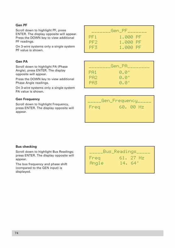
Gen PF
Scroll down to highlight PF, pressENTER. The display opposite will appear.Press the DOWN key to view additionalPF readings.
On 3-wire systems only a single systemPF value is shown.
Gen PA
Scroll down to highlight PA (PhaseAngle), press ENTER. The displayopposite will appear.
Press the DOWN key to view additionalPhase Angle readings.
On 3-wire systems only a single systemPA value is shown.
Gen Frequency
Scroll down to highlight Frequency,press ENTER. The display opposite willappear.
Bus checking
Scroll down to highlight Bus Readings;press ENTER. The display opposite willappear.
The bus frequency and phase shift(compared to the GEN input) isdisplayed.
74

75
PASSWORD PROTECTION
Introduction
Since the product is a front panel mounted device, it could be subjected to tampering oradjustment by unauthorised personnel. The password features allow up to four levels of accesscontrol, so that the range of accessible features can be controlled between total flexibility andtotal lockout.
Using the Password control features to disable unauthorised operation
The product offers four levels of password protection, as follows:● Level 3 – Installation level, allows complete configuration of the product.● Level 2 – Engineering level, allows modification of trip values.● Level 1 – Operator level, trip parameters can be inspected, but not altered.● Level 0 – total lockout of control functions.
All passwords take the form of a number, which can be any value between 1 and 9999.
Password control only affects the operations available at the front panel, however, changes tosystem operation or the trip parameters via the RS485 MODBUS port are not restricted.
Installation level password - Level 3
As shipped from manufacture, the password control is not enabled. This enables full productfunctionality and the maximum flexibility.
With no password control in place, the following main menu options are available:● RELAY STATUS ● RESET TRIPS● POWER METERING● EVENT LOG● CONFIGURATION● PASSWORD● VERSION
From the configuration menu, the product can be set up to suit the intended application. Oncethe product has been wired into electrical circuits, and product functionality has been set, youmay not want the protection functions or physical relays to be to redefined without authority.When the product functionality has been defined and electrically connected, the level 3password can be entered to prevent further alteration of function. The level 3 password will hideany protection features that have not been assigned to relays.

From the main menu, go into thePassword Menu. To set up a passwordfor level 3, scroll down the menu andselect SET LEVEL 3, then press ENTER. Ifthis does not appear in the list, that levelof password protection is already inplace.
Pressing ENTER will allow a newpassword to be entered, which must bea number between 1 and 9999.
Use the UP and DOWN keys to modifythe number. If you press and hold eitherof these keys, the number can be rapidlymodified. Press ENTER to accept thenew value.
Press ESCape to get back to thepassword menu. The password numberthat was just chosen (e.g. 1234) isdisplayed. To activate the passwordcontrol, change this number to anyvalue that is not being used as apassword (e.g. zero)
Once the password has been set, theSET LEVEL 3 option will disappear fromthe password menu, and thefunctionality of relay contacts can not beredefined.
Unlocking a password
To unlock the required level, go into thepassword menu and simply re-enter thepassword number that was configuredfor the access level you require.
76

77
Once a password level has successfullybeen unlocked, you will get menuoptions which allow setting up of newpasswords.
When the level 1 password is correctly entered, you can set a new password for that level only.When level 2 password is correctly entered, you can set new passwords for level 1 and level 2.When the level 3 password is correctly entered, you can set new passwords for all levels.
If a password has been lost or forgotten
If the level 1 or level 2 passwords have been lost or forgotten, entering the correct level 3password will allow these password settings to be reviewed or altered. If the level 3 passwordhas been forgotten, the product must be returned to the factory to be unlocked.
Changing a password
Unlock the product using the old password first, and once the Set Level options appear, simplyset a new password number for the required level.
Switching off password levels
To disable any level of password, youneed to unlock that level first, byentering the correct password. Onceunlocked, change the password numberto zero using the Set Level menu.
Engineering level password – Level 2
Level 2 allows the actual setpoint levels, hysteresis and time delay values to be modified. This isuseful for when equipment is being commissioned, because minor adjustments are usuallymade to these settings to suit local conditions.
Once all of these parameter settings have been altered, further changes can be disabled bysetting a password for level 2. Select SET LEVEL 2 from the password menu, and follow thesame procedure as described for setting level 3.
Once the level 2 password has been set, the configuration menu can not be accessed (in fact,CONFIGURATION does not even appear in the main menu list)

Operator level password - Level 1
At level 1, no parameters can be altered, but the relay trip functions and settings can beinspected from the RESET TRIPS menu. If required an operator can report all of the devicesettings for technical support or problem diagnosis. Only the following main menu options areavailable:
● RELAY STATUS ● RESET TRIPS● POWER METERING● EVENT LOG● PASSWORD● VERSION
Lockout password - Level 0
Once a level 0 password has been set, the event history log and diagnostic information screenscan be viewed, but no changes can be made to the product. Only the following options areavailable from the main menu:
● RELAY STATUS● POWER METERING● EVENT LOG● PASSWORD● VERSION
If relay latching has been enabled, the latch cannot be reset from the front panel. However, if thetrip ALARM mode has been enabled, the alarm can be reset by pressing ENTER in the relaystatus screen.
The password levels are shown on the following pages.
78

79
PASSWORD LEVELS
Menu Functions / SPR-014W (3 Phase 4 Wire) SPR-013W (3 Phase 3 Wire)
Password Level As Level Level Level As Level Level Level
Shipped 3 2 1 Shipped 3 2 1
RELAY STATUS ✔ ✔ ✔ ✔ ✔ ✔ ✔ ✔
Relay Status ✔ ✔ ✔ ✔ ✔ ✔ ✔ ✔
(LCD Constrast) ✔ ✔ ✔ ✔ ✔ ✔ ✔ ✔
RESET TRIPS ✔ ✔ ✔ ✔ ✔ ✔
Reset Trip ✔ ✔ ✔ ✔ ✔ ✔
POWER METERING ✔ ✔ ✔ ✔ ✔ ✔ ✔ ✔
GEN READINGS ✔ ✔ ✔ ✔ ✔ ✔ ✔ ✔
VOLTAGE ✔ ✔ ✔ ✔ ✔ ✔ ✔ ✔
VL1 ✔ ✔ ✔ ✔
VL2 ✔ ✔ ✔ ✔
VL3 ✔ ✔ ✔ ✔
VL1L2 ✔ ✔ ✔ ✔ ✔ ✔ ✔ ✔
VL2L3 ✔ ✔ ✔ ✔ ✔ ✔ ✔ ✔
VL3L1 ✔ ✔ ✔ ✔ ✔ ✔ ✔ ✔
CURRENT ✔ ✔ ✔ ✔ ✔ ✔ ✔ ✔
I1 ✔ ✔ ✔ ✔ ✔ ✔ ✔ ✔
I2 ✔ ✔ ✔ ✔ ✔ ✔ ✔ ✔
I3 ✔ ✔ ✔ ✔ ✔ ✔ ✔ ✔
In ✔ ✔ ✔ ✔
Ig ✔ ✔ ✔ ✔ ✔ ✔ ✔ ✔
POWER ✔ ✔ ✔ ✔ ✔ ✔ ✔ ✔
W1 ✔ ✔ ✔ ✔
W2 ✔ ✔ ✔ ✔
W3 ✔ ✔ ✔ ✔
Wsum ✔ ✔ ✔ ✔ ✔ ✔ ✔ ✔
VA ✔ ✔ ✔ ✔ ✔ ✔ ✔ ✔
VA1 ✔ ✔ ✔ ✔
VA2 ✔ ✔ ✔ ✔
VA3 ✔ ✔ ✔ ✔
VAsum ✔ ✔ ✔ ✔ ✔ ✔ ✔ ✔

80
Menu Functions / SPR-014W (3 Phase 4 Wire) SPR-013W (3 Phase 3 Wire)
Password Level As Level Level Level As Level Level Level
Shipped 3 2 1 Shipped 3 2 1
VAR ✔ ✔ ✔ ✔ ✔ ✔ ✔ ✔
VAr1 ✔ ✔ ✔ ✔
VAr2 ✔ ✔ ✔ ✔
VAr3 ✔ ✔ ✔ ✔
VArsum ✔ ✔ ✔ ✔ ✔ ✔ ✔ ✔
PF ✔ ✔ ✔ ✔ ✔ ✔ ✔ ✔
PF1 ✔ ✔ ✔ ✔
PF2 ✔ ✔ ✔ ✔
PF3 ✔ ✔ ✔ ✔
PFsum ✔ ✔ ✔ ✔ ✔ ✔ ✔ ✔
PA ✔ ✔ ✔ ✔ ✔ ✔ ✔ ✔
PA1 ✔ ✔ ✔ ✔
PA2 ✔ ✔ ✔ ✔
PA3 ✔ ✔ ✔ ✔
PAsum ✔ ✔ ✔ ✔ ✔ ✔ ✔ ✔
FREQUENCY ✔ ✔ ✔ ✔ ✔ ✔ ✔ ✔
Frequency ✔ ✔ ✔ ✔ ✔ ✔ ✔ ✔
BUS READINGS ✔ ✔ ✔ ✔ ✔ ✔ ✔ ✔
Freq ✔ ✔ ✔ ✔ ✔ ✔ ✔ ✔
Angle ✔ ✔ ✔ ✔ ✔ ✔ ✔ ✔
SYSTEM CONFIG ✔ ✔ ✔ ✔ ✔ ✔ ✔ ✔
Sys Volts ✔ ✔ ✔ ✔ ✔ ✔ ✔ ✔
Sys Amps ✔ ✔ ✔ ✔ ✔ ✔ ✔ ✔
Sys Power ✔ ✔ ✔ ✔ ✔ ✔ ✔ ✔
Type ✔ ✔ ✔ ✔ ✔ ✔ ✔ ✔
EVENT LOG ✔ ✔ ✔ ✔ ✔ ✔ ✔ ✔
View ✔ ✔ ✔ ✔ ✔ ✔ ✔ ✔
Clear ✔ ✔ ✔ ✔ ✔ ✔
Summary ✔ ✔ ✔ ✔ ✔ ✔ ✔ ✔

81
Menu Functions / SPR-014W (3 Phase 4 Wire) SPR-013W (3 Phase 3 Wire)
Password Level As Level Level Level As Level Level Level
Shipped 3 2 1 Shipped 3 2 1
CONFIGURATION ✔ ✔ ✔ ✔
RELAYS ✔ ✔ ✔ ✔
Trip Type ✔ ✔
SAVE RELAY SETUP ✔ ✔ ✔ ✔
Save ✔ ✔ ✔ ✔
RANGE ✔ ✔ ✔ ✔
Sys Volts ✔ ✔ ✔ ✔
Sys Amps ✔ ✔ ✔ ✔
Sys Power ✔ ✔ ✔ ✔
Type ✔ ✔ ✔ ✔
TIME & DATE ✔ ✔ ✔ ✔
TIME ✔ ✔ ✔ ✔
Hour ✔ ✔ ✔ ✔
Min ✔ ✔ ✔ ✔
Sec ✔ ✔ ✔ ✔
DATE ✔ ✔ ✔ ✔
Year ✔ ✔ ✔ ✔
Month ✔ ✔ ✔ ✔
Day ✔ ✔ ✔ ✔
COMMS ✔ ✔ ✔ ✔
Baud Rate ✔ ✔ ✔ ✔
Parity ✔ ✔ ✔ ✔
Stop ✔ ✔ ✔ ✔
Node ✔ ✔ ✔ ✔
PASSWORD ✔ ✔ ✔ ✔ ✔ ✔ ✔ ✔
Password ✔ ✔ ✔ ✔ ✔ ✔ ✔ ✔
Set Level 1 ✔ ✔ ✔ ✔ ✔ ✔
Set Level 2 ✔ ✔ ✔ ✔
Set Level 3 ✔ ✔
VERSION ✔ ✔ ✔ ✔ ✔ ✔ ✔ ✔

RS485 DIGITAL OUTPUT - MODBUS IMPLEMENTATION
The SPR offers a RS485 communication INTERFACE for direct connection to SCADA systemsusing the MODBUS RTU protocol. The MODBUS protocol establishes the format for the master'squery by placing into it the device address, a function code defining the requested action, anydata to be sent, and an error checking field.
The slave's response message is also constructed using MODBUS protocol. It contains fieldsconfirming the action taken, any data to be returned, and an error checking field. If an erroroccurred in receipt of the message, or if the slave is unable to perform the requested action, theslave will construct an error message and send it as its response.
The electrical interface is 2-wire RS485 (half duplex), via a 2 part connector. Connection shouldbe made using twisted pair screened cable (Typically 22 gauge Belden 8761 or equivalent). All"A" and "B" connections are daisy chained together. The screens should also be connected tothe “Gnd” terminal. To avoid the possibility of loop currents, an Earth connection should bemade at one point on the network. See the connection diagram for details.
A total maximum length of 1200M (4000 ft) is allowed for the RS485 network. A maximum of 32electrical nodes can be connected, including the controller. The cable should be terminated witha resistor at each end.
The address of each SPR can be set to any value between 1 and 247. Broadcast mode (address0) is not supported.
The maximum latency time of an SPR is 150ms. i.e. this is the amount of time that can passbefore the first response character is output. The supervisory programme must allow this periodof time to elapse before assuming that the SPR is not going to respond.
1. Heavy Modbus traffic can affect the loop time of the product.
2. If an invalid or out of range number is written into a holding register, the SPR will
attempt to set that register to the nearest valid number. It is particularly
important when setting up or modifying trip parameters that all data values are
written and then read back and verified.
82

83
The format for each byte in RTU mode is:
Coding System: 8-bit binary, hexadecimal 0-9, A-F
Two hexadecimal characters contained in each 8-bit fieldof the message.
Data Format: 4 bytes (32 bits) per parameter.Floating point format ( to IEEE 754)
Byte Order: Most significant byte first. Can be reversed in the setup menu
Bits per Byte: 1 start bit8 data bits, least significant bit sent first1 bit for even/odd parity; no bit for no parity1 stop bit if even or odd parity is used; 2 stop bits if no parity, standard settings but programmable for different requirements.
Error Check Field: Cyclical Redundancy Check (CRC).
Data Transmission speed is selectable between 2400, 4800, 9600, 19200 bps.
All settings are user configurable via the setup screens.
Modbus Specification
Communication Parameters
The communication port on the SPR has the following characteristics.
Parameter Values
Media 3 Wire, (A, B, Ground) RS485
Multidrop 32 Standard Loads, SPR = 1 Standard Load
Protocol Modbus RTU
Baud Rate 2400 / 4800 / 9600 / 19200
Parity Odd / Even / None
Stop Bits 1 or 2
Response Time 150 mSec (Max), 80mSec (Typical)
Register Representation 4 Byte IEEE 754, represented as register pairs, big endian byte order
Functions Supported Read Input Registers ( 04)Read Holding Registers (03)Write Holding Registers (16)
Exception Codes Illegal function (01)Illegal Data Address ( 02)Illegal Data Value ( 03)

Input Registers (3x)
These registers are read only, and give the values being measured by the SPR.
Measurement Registers
The available registers are indicated in the following table. There are differences between 3-wire(SPR-013) and 4-wire (SPR-014) practices. A tick (✔) in the system configuration columnindicates that the parameter is valid for that wiring system, a cross (X) will return the value zero.
Table 2 Measurement Registers
Address Address Parameter 4 Wire 3 Wire Access
(Register) (Hex) SPR-014 SPR-013
30001 00 00 Volts 1 ✔ ✔ Read only
30003 00 02 Volts 2 ✔ ✔ Read only
30005 00 04 Volts 3 ✔ ✔ Read only
30007 00 06 Current 1 ✔ ✔ Read only
30009 00 08 Current 2 ✔ ✔ Read only
30011 00 0A Current 3 ✔ ✔ Read only
30013 00 0C Watts 1 ✔ X Read only
30015 00 0E Watts 2 ✔ X Read only
30017 00 10 Watts 3 ✔ X Read only
30019 00 12 VA 1 ✔ X Read only
30021 00 14 VA 2 ✔ X Read only
30023 00 16 VA 3 ✔ X Read only
30025 00 18 VAr 1 ✔ X Read only
30027 00 1A VAr 2 ✔ X Read only
30029 00 1C VAr 3 ✔ X Read only
30031 00 1E Power Factor 1 ✔ X Read only
30033 00 20 Power Factor 2 ✔ X Read only
30035 00 22 Power Factor 3 ✔ X Read only
30037 00 24 Phase Angle 1 ✔ X Read only
30039 00 26 Phase Angle 2 ✔ X Read only
30041 00 28 Phase Angle 3 ✔ X Read only
30043 00 2A Volts Average ✔ ✔ Read only
30047 00 2E Current Average ✔ ✔ Read only
84

85
Address Address Parameter 4 Wire 3 Wire Access
(Register) (Hex) SPR-014 SPR-013
30001 00 00 Volts 1 ✔ ✔ Read only
30049 00 30 Current Sum ✔ ✔ Read only
30053 00 34 Watts Sum ✔ ✔ Read only
30057 00 38 VA Sum ✔ ✔ Read only
30061 00 3C VAr Sum ✔ ✔ Read only
30071 00 46 Frequency ✔ ✔ Read only
30201 00 C8 V L1-L2 (Calculated) ✔ ✘ Read only
30203 00 CA V L2-L3 (Calculated) ✔ ✘ Read only
30205 00 CC V L3-L1 (Calculated) ✔ ✘ Read only
30207 00 CE V L-L Average ✔ ✘ Read only
30225 00 E0 I Neutral ✔ ✘ Read only
30227 00 E2 Bus Frequency ✔ ✔ Read only
30229 00 E4 Bus-Gen Phase Angle ✔ ✔ Read only
30231 00 E6 Bus Volts ✔ ✔ Read only
30233 00 E8 I Ground ✔ ✔ Read only
Event Log Registers
The event log can be accessed as part of the input register space, the addresses are shown inTable 3.
Table 3 Event Log Registers
Address Address Parameter Access
(Register) (Hex)
30799 03 1E Event Number Read only
30801 03 20 Relay Number for Event Read only
30803 03 22 Year Read only
30805 03 24 Month Read only
30807 03 26 Day Read only
30809 03 28 Hour Read only
30811 03 2A Minute Read only
30813 03 2C Second Read only
30815 03 2E Increment (reading this will Read onlyreturn the next event next time)

Holding Registers (4x)
These registers are read write and are defined in the following sections.
System Registers
These are a subset of the integra.
Address Address Parameter 4 Wire 3 Wire Access
(Register) (Hex) SPR-014 SPR-013
40007 00 06 System Voltage ✔ ✔ Read / Write
40009 00 08 System Current ✔ ✔ Read / Write
40011 00 0A System Type ✔ ✔ Read only
Relay Registers
These consist of a block of 9 registers per trip, giving a total of 160 registers for the 16 tripproduct. They are all mapped into the same address space, as shown in Table 4. The value sentto ‘Relay Number’ determines which relay is being addressed.
Table 4 Relay Registers
Address Address Parameter Access
(Register) (Hex)
40059 00 3A Relay Number Read/Write
40061 00 3C Trip Function Read/Write
0063 00 3E Trip Mode Read/Write
40065 00 40 Trip Status Read/Write
40067 00 42 Trip 1st Parameter Read/Write
40069 00 44 Trip 2nd Parameter Read/Write
40071 00 46 Trip 3rd Parameter Read/Write
40073 00 48 Trip 4th Parameter Read/Write
40075 00 4A Trip 5th Parameter Read/Write
40077 00 4C Trip 6th Parameter Read/Write
86

87
Relay Number
The value sent to the ‘Relay Number’ register determines which relay is being addressed. Detailsfor that relay can then be accessed through the other registers. To save the relay settings, senda zero to this register.
Trip Function
This is an enumerated type which determines the trip function.
Trip Mode
This is a bit set, returned as a floating point number it has the following values, which may beadded for composites functions. The setting is binary weighted, eg. A register setting of 3indicates inverted and alarm functions are enabled (1 + 2 = 3).
Function Value
Failsafe 1
Alarm 2
Latched 4
Number Function ANSI
0 Unused1 Over Voltage 592 Under Volts 273 Over Frequency 81O4 Under Frequency 81U5 Reverse Power 32R6 Unbal Volts 477 I/T+V.R. 51V8 I/T 519 Ground Fault 51G10 Sync 2511 Sync+DB 25D12 Phase Order 4713 Logical AND14 Logical OR15 Logical NAND16 Logical NOR17 Logical XOR18 Logical Vote19 Logical Disc20 Alarm21 Unack Alarm22 Over Amps 5023 Under Amps 3724 Over Amps 50N25 Over Power 32O26 Reverse VAr 40Q27 UnBal Amps 46

Trip Status
This is a bit set, and has the functions shown below.
Name Description Value Access
CurrentState The current state of the trip condition 1 R
Active The current state of the latch ( if set ) 2 R
Acked Acknowledged the alarm 4 R/W
InAlarm The trip is in alarm 8 R
ClearLatch Set to clear the latch 16 W
Trip Parameters ( 1 to 6 )
These are the other parameters for the trip. The use of these is dependent on the trip type, andrelate directly to the menu layout through the front panel. Check the products’ menu system formore specific information.
RTC Registers
This area gives access to the real time clock and has the registers shown in below.
Address Address Parameter Access
(Register) (Hex)
40099 00 62 Year Read/Write
40101 00 64 Month Read/Write
40103 00 66 Day Read/Write
40105 00 68 Hour Read/Write
40107 00 6A Minute Read/Write
40109 00 6C Second Read/Write
88

89
PRODUCT SPECIFICATION
INPUTS
Voltage
Nominal Four wire units:57.7 to 70 VL-N (ac rms)110 to 139 VL-N
220 to 277 VL-N
Three wire units:100 to 120 VL-L (ac rms)190 to 240 VL-L
380 to 480 VL-L
Max continuous input voltage 120%
Max short duration voltage overload 2 * nominal (1s application repeated 10 times at 10s intervals)
Burden (per phase) ≈ 0.2 VA
System VT (Bus and Generator) primary ≤ 400 kVAC
value
Current
Nominal 5 ARMS
1 ARMS (Option)
System CT primary ≤ 10 kAAC
values
Max continuous input 200% current
Max short duration 20 * nominal (1s current overload application repeated 5 times at 5 min intervals)
Burden (per phase) ≈ 0.6 VA
OUTPUTS
Relays
Watchdog (Dedicated) 1
The watchdog relay will be energised when the software has successfully completed itsinitialisation and has verified the contents of the calibration data.
If normal program execution or auxiliary supply fails, the relay will de-energize.
User Assigned
Standard 8
with the relay option 12

90
OUTPUTS (continued)
Relays
Contacts
Configuration 1 C/O (NO+NC)
Type of contact Single Contact
Rated Voltage 250 VAC
Max Breaking Voltage 440 VAC
Rated Current 8 A (Resistive load)
Make Current 30 A (4s @ < 10% duty cycle)
Rated Breaking Capacity 2000 VA
Dielectric test voltage 1000 Vrms (between contacts)
Maximum frequency of operation 0.1 cycles/second @ rated load
Contact Life
B300/120VAC /70°C UL 508
B300/240VAC /70°C UL 5081/4 HP/120VAC /70°C UL 508
8 A/28VDC /70°C 30000 ops
0.28 A/250VDC /70°C 30000 ops
General
Mechanical Life > 30 million operations
DISPLAY
Rows 4
Columns 20
Type LCD
Backlight LED
Color Yellow/Green
AUXILIARY SUPPLY (24V)
Nominal Supply 24Vdc
Auxiliary supply range 10.6 .. 55Vdc.
Burden <20VA
Operation above 55V or extended operation below 10.6V may cause product malfunction ordamage.

91
REAL TIME CLOCK
Accuracy ± 1 minute per month
Ageing ± 3 ppm (parts per million) per year
Resolution 0.1 seconds
Battery Type Lithium (Return product to factory for replacement)
Battery Life (No auxiliary) 3 years
MEASURING RANGES
Values of measured quantities for which errors are defined.
Voltage 20 … 120%
Current 20 ….. 120% (functional 5%...500%)
Frequency 45 … 66 Hz
Active power (Watt) 5 ….. 120%
Power Factor 0.5..1..0.5, Importing or Exporting
ACCURACY AND RESOLUTION
The electrical measurements and trip functions have the following accuracy levels. Theresolution of these settings or measurements will change dynamically, depending on any PT orCT ratio settings. Under some operating conditions, occasionally single values observed viamodbus may lie slightly outside specified accuracy limits. However preceding and succeedingvalues will be within specified limits.
Voltage
Accuracy +/- 1% of nominal input voltage
Resolution 0.1 Volt for system Voltages of 57.7 to 999.9V 1 Volt for system Voltages of 1kV to 9.999kV 10 Volt for system Voltages of 10kV to 99.99kV 100 Volt for system Voltages of 100kV to 400kV
Current
Accuracy +/- 2.5% of nominal input
Resolution 0.01A for system currents of 0.01 A to 99.99 Amps0.1A for system currents of 100 A to 999.9 Amps1A for system currents of 1 kA to 9.999 kA
Frequency
Accuracy +/- 0.03 Hz of nominal
Resolution 0.01 Hz

Phase Angle
Accuracy +/- 1 degree
Resolution 0.1 degree
Time Delay
Accuracy +/- 0.1 second
Resolution 0.1 second
Default The default time delay for many trips is 0.2 seconds. This can be reduced in some cases, but trip points should be reviewed to minimise nuisance tripping.
Active Power (Watts)
Accuracy +/- 3% of nominal input watts
Resolution 0.1 W for system powers/phase of 57.7 W to 999.9 W1 W for system powers/phase of 1 kW to 9.999 kW10 W for system powers/phase of 10 kW to 99.99 kW100 W for system powers/phase of 100 kW to 999.9 kW1 kW for system powers/phase of 1 MW to 9.999 MW10 kW for system powers/phase of 10 MW to 99.99 MW
Reactive Power (VAr)
Accuracy +/- 4% of nominal input VAr
Resolution 0.1 VAr for system powers/phase of 57.7 VAr to 999.9 VAr1 VAr for system powers/phase of 1 kVAr to 9.999 kVAr10 VAr for system powers/phase of 10 kVAr to 99.99 kVAr100 VAr for system powers/phase of 100 kVAr to 999.9 kVAr1 kVAr for system powers/phase of 1 MVAr to 9.999 MVAr10 kVAr for system powers/phase of 10 MVAr to 99.99 MVAr
STANDARDS
Terms, Definitions and Test Methods
BS EN 60255-6 (Multi input measuring relay with Dependent time relay with decreasing functioncapability)
ANSI/IEEE C37.90 (Output Circuits Not Rated for Tripping)
EMC
Emissions – BS EN 61326 : 1998
Emissions (Class A equipment)
Radiated IMMUNITY – BS EN 61326 : 1998
Enclosure 10 V/m, Conducted 3V, ESD 8 kV, High frequency disturbance 2 kV
92

IEC255-4 (BS EN 60255-4)
3.25 kV peak on all measuring inputs
Safety
IEC1010-1 (BS EN 61010-1)
Permanently connected use, Normal Condition, Installation category III, pollution degree 2, BasicInsulation, 600 VRMS.
UL508
Standard for Industrial Control Equipment
EU Directives
EMC Directive 89/336/EEC amended by 93/68/EEC
Low Voltage Directive 89/336/EEC amended by 93/68/EEC
ENVIRONMENTAL
Standard operating temperature 0°C to +50°C
Extended operating temperature -20°C to +60°C (Contact factory)
Storage temperature -20°C to +70°C
Relative humidity 0 to 95% non-condensing
Altitude ≤ 3000 metres above sea level
Shock 30g in 3 planes
Vibration 10 to 150 Hz, 1 g amplitude
Enclosure code (front) IP54 with optional gasket
Harmonic distortion Up to 8th harmonic (10% THD)
ENCLOSURE
Style Custom, to fit panel aperture of 186mm x 92mm (7.32 x 3.62 inches)
Material Zinc Passivated Steel with Polycarbonate front panel
Size 200mm (7.88”) wide, 106mm (4.18”) high, 200mm (7.88”) deep. Includes connectors but excludes cable bending radius and fixing clamps. See dimensions on page 7.
Weight < 3 kg
93

94
SERIAL COMMUNICATIONS
Modbus RTU
Parameter Values
Media 3 Wire, (A, B, Ground) RS485
Multidrop 32 Standard Loads, SPR = 1 Standard Load
Protocol Modbus RTU
Baud Rate 2400/4800/9600/19200
Parity Odd/Even/None
Stop Bits 1 or 2
Response Time 150 mSec (Max), 80mSec (Typical)
Register Representation 4 Byte IEEE 754, represented as register pairs, big endian byte order - can be reversed
Functions Supported Read Input Registers ( 04)Read Holding Registers (03)Write Holding Registers (16)
Exception Codes Illegal function (01)Illegal Data Address ( 02)Illegal Data Value ( 03)
SPECIFICATION APPROVAL
UL and CSA recignised File No. E214293Railtrack Certificate of AcceptancePA051/1450. Scope: Protective Deviceon Signalling Power Supply Systems

Notes

Notes

Tyco
Ele
ctr
on
ics
SP
RM
AN
UA
L 0
3/0
8
Energy Division
With 4000 employees and more than 6000 customers world-wide, the Energy Division represents a very significant part ofTyco Electronics. Based in headquarters in Ottobrunn, nearMunich, Germany, the Energy Division is a global supplier topower utilities and power industry customers, to equipmentmanufacturers and transport systems. These customers areserved by dedicated R&D teams, sales, representatives inmore than 80 countries, a professional marketing organizationand 25 manufacturing sites in five continents.
Tyco Electronics UK LtdEnergy DivisionFreebournes RoadWitham, Essex CM8 3AH
Phone: +44 (0)870 7500Fax: +44 (0)870 240 5287Email: [email protected]
www.crompton-instruments.comhttp://energy.tycoelectronics.com Our commitment. Your advantage.
All of the above information, including drawings, illustrations and graphic designs, reflects our present understanding and is to the best ofour knowledge and belief correct and reliable. Users, however, should independently evaluate the suitability of each product for the desiredapplication. Under no circumstances does this constitute an assurance of any particular quality or performance. Such an assurance is onlyprovided in the context of our product specifications or explicit contractual arrangements. Our liability for these products is set forth in ourstandard terms and conditions of sale. TE logo and Tyco Electronics are trademarks. CROMPTON is a trademarks of Crompton Parkinson Ltd.and is used by Tyco Electronics under licence.
Energy Division – economical solutions for the electrical power industry: cable accessories, connectors & fittings, electrical equipment,instruments, lighting controls, insulators & insulation enhancement and surge arresters.