Installation and Operating Instructions 0158 Lumiglas ... … · • Important , please note: Sight...
5
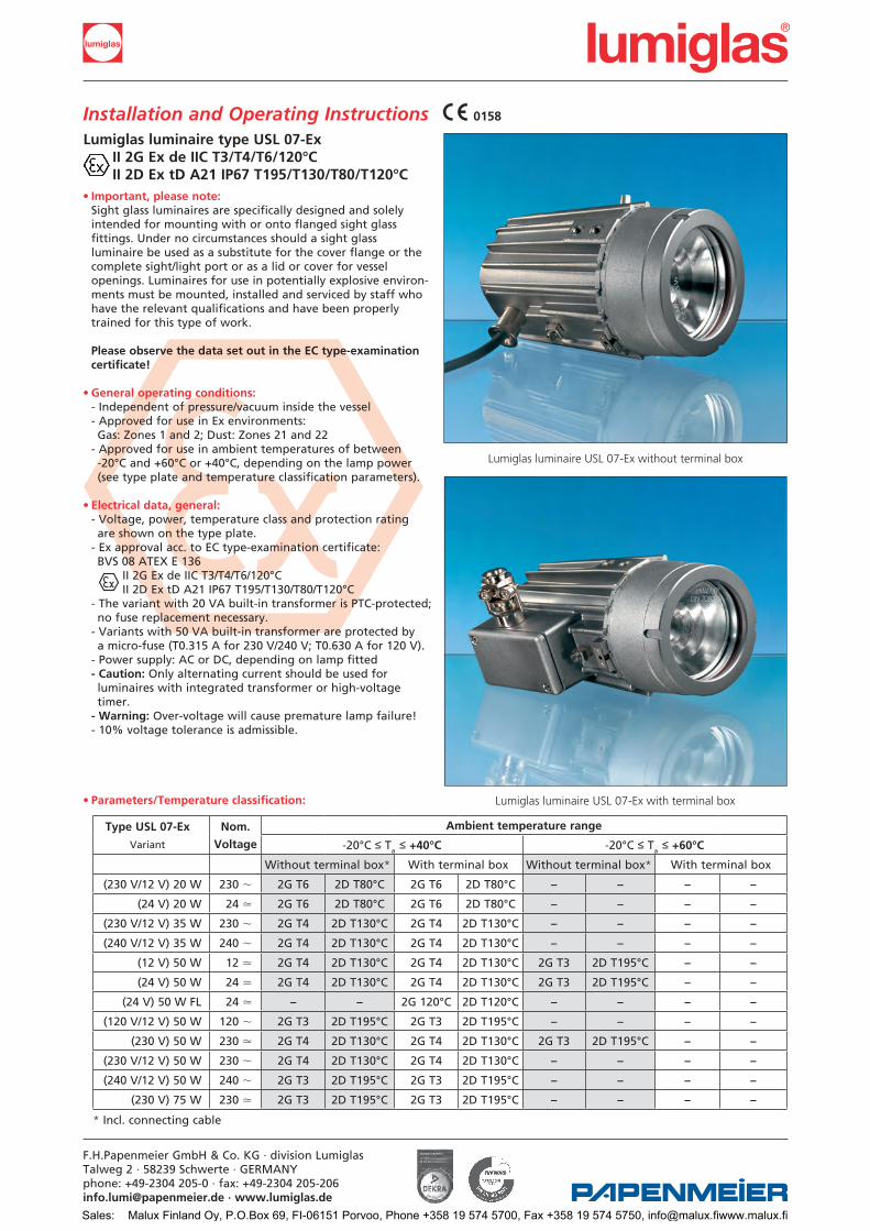
• Important, please note: Sight glass luminaires are specifically designed and solely intended for mounting with or onto flanged sight glass fittings. Under no circumstances should a sight glass luminaire be used as a substitute for the cover flange or the complete sight/light port or as a lid or cover for vessel openings. Luminaires for use in potentially explosive environ- ments must be mounted, installed and serviced by staff who have the relevant qualifications and have been properly trained for this type of work. Please observe the data set out in the EC type-examination certificate! • General operating conditions: - Independent of pressure/vacuum inside the vessel - Approved for use in Ex environments: Gas: Zones 1 and 2; Dust: Zones 21 and 22 - Approved for use in ambient temperatures of between -20°C and +60°C or +40°C, depending on the lamp power (see type plate and temperature classification parameters). • Electrical data, general: - Voltage, power, temperature class and protection rating are shown on the type plate. - Ex approval acc. to EC type-examination certificate: BVS 08 ATEX E 136 II 2G Ex de IIC T3/T4/T6/120°C II 2D Ex tD A21 IP67 T195/T130/T80/T120°C - The variant with 20 VA built-in transformer is PTC-protected; no fuse replacement necessary. - Variants with 50 VA built-in transformer are protected by a micro-fuse (T0.315 A for 230 V/240 V; T0.630 A for 120 V). - Power supply: AC or DC, depending on lamp fitted - Caution: Only alternating current should be used for luminaires with integrated transformer or high-voltage timer. - Warning: Over-voltage will cause premature lamp failure! - 10% voltage tolerance is admissible. • Parameters/Temperature classification: Lumiglas luminaire type USL 07-Ex II 2G Ex de IIC T3/T4/T6/120°C II 2D Ex tD A21 IP67 T195/T130/T80/T120°C F.H.Papenmeier GmbH & Co. KG · division Lumiglas Talweg 2 · 58239 Schwerte · GERMANY phone: +49-2304 205-0 · fax: +49-2304 205-206 [email protected] · www.lumiglas.de Installation and Operating Instructions 0158 Type USL 07-Ex Variant Nom. Voltage Ambient temperature range -20°C ≤ T a ≤ +40°C -20°C ≤ T a ≤ +60°C Without terminal box* With terminal box Without terminal box* With terminal box (230 V/12 V) 20 W 230 , 2G T6 2D T80°C 2G T6 2D T80°C – – – – (24 V) 20 W 24 . 2G T6 2D T80°C 2G T6 2D T80°C – – – – (230 V/12 V) 35 W 230 , 2G T4 2D T130°C 2G T4 2D T130°C – – – – (240 V/12 V) 35 W 240 , 2G T4 2D T130°C 2G T4 2D T130°C – – – – (12 V) 50 W 12 . 2G T4 2D T130°C 2G T4 2D T130°C 2G T3 2D T195°C – – (24 V) 50 W 24 . 2G T4 2D T130°C 2G T4 2D T130°C 2G T3 2D T195°C – – (24 V) 50 W FL 24 . – – 2G 120°C 2D T120°C – – – – (120 V/12 V) 50 W 120 , 2G T3 2D T195°C 2G T3 2D T195°C – – – – (230 V) 50 W 230 . 2G T4 2D T130°C 2G T4 2D T130°C 2G T3 2D T195°C – – (230 V/12 V) 50 W 230 , 2G T4 2D T130°C 2G T4 2D T130°C – – – – (240 V/12 V) 50 W 240 , 2G T3 2D T195°C 2G T3 2D T195°C – – – – (230 V) 75 W 230 . 2G T3 2D T195°C 2G T3 2D T195°C – – – – * Incl. connecting cable Lumiglas luminaire USL 07-Ex without terminal box Lumiglas luminaire USL 07-Ex with terminal box Sales: Malux Finland Oy, P.O.Box 69, FI-06151 Porvoo, Phone +358 19 574 5700, Fax +358 19 574 5750, [email protected]
Transcript of Installation and Operating Instructions 0158 Lumiglas ... … · • Important , please note: Sight...
•Important,pleasenote: Sight glass luminaires are specifically designed and solely intended for mounting with or onto flanged sight glass fittings. Under no circumstances should a sight glass luminaire be used as a substitute for the cover flange or the complete sight/light port or as a lid or cover for vessel openings. Luminaires for use in potentially explosive environ- ments must be mounted, installed and serviced by staff who have the relevant qualifications and have been properly trained for this type of work. PleaseobservethedatasetoutintheECtype-examination certificate!
•Generaloperatingconditions: - Independent of pressure/vacuum inside the vessel - Approved for use in Ex environments: Gas: Zones 1 and 2; Dust: Zones 21 and 22 - Approved for use in ambient temperatures of between -20°C and +60°C or +40°C, depending on the lamp power (see type plate and temperature classification parameters).
•Electricaldata,general: - Voltage, power, temperature class and protection rating are shown on the type plate. - Ex approval acc. to EC type-examination certificate: BVS 08 ATEX E 136 II 2G Ex de IIC T3/T4/T6/120°C II 2D Ex tD A21 IP67 T195/T130/T80/T120°C - The variant with 20 VA built-in transformer is PTC-protected; no fuse replacement necessary. - Variants with 50 VA built-in transformer are protected by a micro-fuse (T0.315 A for 230 V/240 V; T0.630 A for 120 V). - Power supply: AC or DC, depending on lamp fitted -Caution: Only alternating current should be used for luminaires with integrated transformer or high-voltage timer. -Warning: Over-voltage will cause premature lamp failure! - 10% voltage tolerance is admissible.
•Parameters/Temperatureclassification:
LumiglasluminairetypeUSL07-Ex II2GExdeIICT3/T4/T6/120°C II2DExtDA21IP67T195/T130/T80/T120°C
F.H.Papenmeier GmbH & Co. KG · division LumiglasTalweg 2 · 58239 Schwerte · GERMANYphone: +49-2304 205-0 · fax: +49-2304 [email protected] · www.lumiglas.de
Installation and Operating Instructions 0158
TypeUSL07-Ex
Variant
Nom.
Voltage
Ambienttemperaturerange
-20°C ≤ Ta ≤ +40°C -20°C ≤ Ta ≤ +60°C
Without terminal box* With terminal box Without terminal box* With terminal box
(230 V/12 V) 20 W 230 , 2G T6 2D T80°C 2G T6 2D T80°C – – – –
(24 V) 20 W 24 . 2G T6 2D T80°C 2G T6 2D T80°C – – – –
(230 V/12 V) 35 W 230 , 2G T4 2D T130°C 2G T4 2D T130°C – – – –
(240 V/12 V) 35 W 240 , 2G T4 2D T130°C 2G T4 2D T130°C – – – –
(12 V) 50 W 12 . 2G T4 2D T130°C 2G T4 2D T130°C 2G T3 2D T195°C – –
(24 V) 50 W 24 . 2G T4 2D T130°C 2G T4 2D T130°C 2G T3 2D T195°C – –
(24 V) 50 W FL 24 . – – 2G 120°C 2D T120°C – – – –
(120 V/12 V) 50 W 120 , 2G T3 2D T195°C 2G T3 2D T195°C – – – –
(230 V) 50 W 230 . 2G T4 2D T130°C 2G T4 2D T130°C 2G T3 2D T195°C – –
(230 V/12 V) 50 W 230 , 2G T4 2D T130°C 2G T4 2D T130°C – – – –
(240 V/12 V) 50 W 240 , 2G T3 2D T195°C 2G T3 2D T195°C – – – –
(230 V) 75 W 230 . 2G T3 2D T195°C 2G T3 2D T195°C – – – –
* Incl. connecting cable
Lumiglas luminaire USL 07-Ex without terminal box
Lumiglas luminaire USL 07-Ex with terminal box
Sales: Malux Finland Oy, P.O.Box 69, FI-06151 Porvoo, Phone +358 19 574 5700, Fax +358 19 574 5750, [email protected]
a) VariantI(withoutterminalbox,incl.connectingcable) - The connecting cable has been factory-installed in the luminaire and is ready for use. - The external protective conductor terminal (1) should be connected to a separate operational earth. - The connecting cable should be supported after a max. distance of 1 m from entry gland. - Caution: If the cable is to be replaced (e. g. by one of a different length), the internal terminals have to be disconnected before unscrewing the cable entry gland. Specialconditions: Ex-type luminaires that do not have a terminal box are manufactured with a permanently connected cable. If connection is carried out in a potentially explosive environment, the free ends of the connecting cable must be installed in a category 2G/2D enclosure. Prior to installation and when servicing the luminaire without a terminal box, the luminaire and the surroun- ding area should first be cleaned to remove any dust. During installation or servicing, the disassembled parts should be protected against dirt and dust. Before closing the lamp again, it is essential to take extra care and ensure that the inside of the luminaire is free of dust.
b) VariantII(withterminalbox) - Select a connecting cable to fit the cable entry gland M20 x 1.5. If the ambient temperature is greater than 40°C, heat- resistant cable, e.g. Sinotherm 110 H05GG-F3G 1.5 mm² should be used. The minimum heat resistance of the connecting cable is shown on the type plate, if applicable. - Open the cover of the terminal box. - Loosen strain relief screws with anti-twist tabs on the cable gland assembly. - Insert cable, seal, tighten screws again.
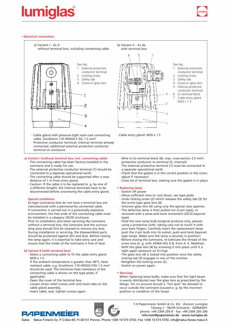
Part No.1 External protective conductor terminal2 Locking screw3 Safety tab4 Screw-in glass lens
F.H.Papenmeier GmbH & Co. KG · division LumiglasTalweg 2 · 58239 Schwerte · GERMANY
phone: +49-2304 205-0 · fax: +49-2304 [email protected] · www.lumiglas.de
a) Variant I – Ex d without terminal box, including connecting cable
•Electricalconnection:
- Wire to Ex terminal block (6); max. cross-section 2.5 mm²; protective conductor to terminal (5, internal). The external protective terminal (1) must be connected to a separate operational earth. - Check that the gasket is in the correct position in the cover; adjust if necessary! - Close lid of terminal box, making sure the gasket is in place. •Replacinglamp: - Switch off power - Allow sufficient time to cool down, see type plate. - Undo locking screw (2) which releases the safety tab (3) for the screw-type glass lens (4). - Unscrew glass lens (4) using only the special claw spanner. - The defective lamp is then pulled out (2-pin type), or removed with a press-and-twist movement (GZ10 bayonet type). - Hold the new lamp bulb (original products only, please) using a protective cloth, taking care not to touch it with your bare fingers. Carefully insert the replacement lamp: push the 2-pin bulb into its socket, push-and-twist bayonet type lamps. Make sure the lamp is securely in position! - Before closing the luminaire, re-lubricate the thread of the screw lens (e. g. with AEMA-SOL 6 B, from A. E. Matthes). - Refit the glass lens (4) by screwing it into place until it is tight again (pressure on O-ring). - The glass lens (4) is locked into position once the safety locking tab (3) engages in one of the notches. - Retighten the locking screw (2). - Switch on power again.
•Warning: When replacing lamp bulbs, make sure that the light beam is evenly distributed over the glass lens as prescribed by the design. On no account should a “hot spot” be allowed to occur outside the luminaire (caused e. g. by the incorrect position or condition of the lamp).
- Cable gland with pressure-tight resin-cast connecting cable, Sinotherm 110 H05GG-F 3G, 1.5 mm²- Protective conductor terminal: Internal terminal already connected, additional external protective conductor terminal on enclosure.
- Cable entry gland: M20 x 1.5
Part No.1 External protective conductor terminal2 Locking screw3 Safety tab4 Screw-in glass lens 5 Internal protective conductor terminal6 Ex terminal block7 Cable entry gland M20 x 1.5
b) Variant II – Ex de with terminal box
7
Sales: Malux Finland Oy, P.O.Box 69, FI-06151 Porvoo, Phone +358 19 574 5700, Fax +358 19 574 5750, [email protected]

•Mechanicalinstallation: With circular sight glass fittings or visual flow indicators, the luminaire is attached to the cover flange using the hinged bracket. With the screw-type sight glass fitting, the luminaire is attached to the slotted cover nut; alternatively, it can be mounted using a hinged bracket or a flanged adapter collar.
•TheLumiglasluminaireTypeUSL07-Exissuitableforsight glassesinthefollowingnominalsizesusingtheappropriate mounting:
•Attachmentwithluminairemounting: The luminaire is attached to the cover flange of a circular sight glass unit or flow indicator or to the slotted cover nut of screw-type sight glass fittings to DIN 11851 using the mounting parts – straight or angular bracket. Straight bracket for DN 50 to 100 Angular bracket for DN 125 to 200
•Mountingwithflangedadaptercollar: The flanged adapter collar is bolted or welded to the slotted cover nut (DIN 11851).
•Pleasenote:Fasteners and claw spanner should be ordered separately, if required.
• Replacementparts: Part No. Screw-type lens (light aperture) 1774.038.00 Reflector, spot 5904.049.00 Reflector, flood 5904.050.00 O-ring seal (Viton) 0862.040.00 Lamp socket G 4 (2-pin) 1202.011.00 Lamp socket GY 6.35 (2-pin) 1202.012.00 Lamp socket GZ 10 1202.024.00 Flat gasket for terminal box cover 0854.058.00 Cable entry gland: complete with 2 m connecting cable 1084.013.00 complete with 5 m connecting cable 1084.015.00 complete with 20 m connecting cable 1084.017.00 Flared cable entry gland (M20 x 1.5) 9108.008.00 (Halogen) lamps: 12 V/20 W – GY6.35 3232.240.00 24 V/20 W – G4 3232.206.00 12 V/35 W – GY6.35 3232.232.00 12 V/50 W – GY6.35 3232.238.00 24 V/50 W – GY6.35 3232.242.00 230 V/50 W – GZ10 3232.261.00 230 V/75 W – GZ10 3232.263.00 •Accessories: Claw spanner 6805.002.00
•Servicing: - Keep luminaire clean and free of dust. - Keep note of average lamp life. - Use only original replacement parts.
F.H.Papenmeier GmbH & Co. KG · division LumiglasTalweg 2 · 58239 Schwerte · GERMANYphone: +49-2304 205-0 · fax: +49-2304 [email protected] · www.lumiglas.de
Application as combined sight and light port on a sight glass fitting acc. to DIN 28120, mounting by way of hinged bracket
As a light glass:Straight luminaire mountingPart No.: 1.0354.005.91For DN 50 – DN 100
As a light and sight glass:Angular luminaire mountingPart No.: 1.0354.006.91For DN 125 – DN 200
DN 100
DN 125
Combination options
typeoffitting fromHingedbracket Flangedadap- Circular sightglass fitting DIN 28120 50 … + – DIN 28121 50 … + – Visual flow indicator 50 … + – Screw-type sightglass 65 – + fitting 80 – + similar to DIN 11851 100 – + 125 + +
DN tercollar
Sales: Malux Finland Oy, P.O.Box 69, FI-06151 Porvoo, Phone +358 19 574 5700, Fax +358 19 574 5750, [email protected]

All dimensions in mm unless stated otherwise. Subject to change without prior notice.WW 09.09 0093.051.00
F.H.Papenmeier GmbH & Co. KG · division LumiglasTalweg 2 · 58239 Schwerte · GERMANY
phone: +49-2304 205-0 · fax: +49-2304 [email protected] · www.lumiglas.de
Sales: Malux Finland Oy, P.O.Box 69, FI-06151 Porvoo, Phone +358 19 574 5700, Fax +358 19 574 5750, [email protected]
F.H.Papenmeier GmbH & Co. KG · division LumiglasTalweg 2 · 58239 Schwerte · GERMANYphone: +49 2304 205-0 · fax: +49 2304 [email protected] · www.lumiglas.de
®
All dimensions in mm unless stated otherwise. Subject to change without prior notice.WW 02.09 3755.157
Important guidelines for mounting and use of sight glass fittings, toughened glasses and luminaires:Before installation and operation/servicing, please read and follow all commissioning and servicing instructions.
1. Installation of sight glass fittings The installation by welding, brazing etc, must be free of distortion
and thus carried out by suitably qualified and authorized personnel.
2. Installing toughened glass discs into a sight glass assembly2.1 Operating safety of sight glasses depends to a great extent upon their
correct installation.2.2 The gasket seating surfaces in the flanges must be plane, flat and
smooth. Ensure the gasket edges are not trapped by, or foul, the flange gasket recess wall.2.3 The glass disc, with gaskets appropriate to the process application fitted to its top and bottom faces must be located concentrically in
the flange assembly.2.4 Only use gaskets which are in good condition, flat and free of dirt
and grease.2.5 Before tightening nuts or bolts ensure once more that cover and base
flanges are correctly aligned and surfaces parallel to one another.2.6 Tighten the nuts or bolts progressively in diametrically opposed pairs.
Tightening moments can be obtained from the relevant data sheets accompanying product (or consult supplier).
2.7 Further tightening down may be required after assembly has bedded down under operating temperature and pressure.
2.8 When installing quartz sight glass discs follow manufacturers’ instructions!
3. Max. loading of toughened sight glass discs3.1 Correctly fitted sight glass discs must be used within the working temperature and pressure ranges laid down for them otherwise they
may fail.3.2 Temperature cycling to be within permitted limits: •Sodalimeglass(DIN8902),maxpermissibletemperature:+150°C. Temperaturechangewithinoneminutemaxfrom120°Cto20°C
with glass fully immersed. •Borosilicateglass(DIN7080),maxpermissibletemp.:+280°C. Temperaturechangewithinoneminutemaxfrom230°Cto20°C
with glass fully immersed.3.3 Avoid spraying sight glasses which are still hot with cold fluid. Warning! This can lead to glass disc breakage.3.4 Safety Precautions when using sight glass discs: 3.4.1 Scheduled Maintenance: Sight glasses must be included in preventive maintenance, and regularly checked either visually or by ultra sound measurement of
wall thickness. Where a disc shows any damage it must be exchanged promptly with the plant shut down. Further, a thorough and regular check of the sight glass should lead to a down time to suit the
par ticular vessel; this will promote a routine for glass exchange suited to the process.
3.4.2 Breakage of glass disc: Inspiteofcarefulfittingandoperationinaccordancewithinstruc-
tions, it is possible though rare, that due to external effects a glass disccanfail.Itisnecessary,particularlyinthecaseofcriticalprocessessuch as in the food industry, that the plant manufacturer or operator takes appropriate safety measures to prevent glass fragments finding their way into the product.
3.5 After dismantling a sight glass assembly, and in accordance with DIN7080standardrequirementsforalltypeofsightglassdisc,the
glass disc and gaskets are replaced with new ones before the assembly is put back into operation. This is particularly important
where pressure vessels and/or aggressive media are concerned. ThefollowingwordingasextractedfromDIN7080refers: “Sight glass discs may only be installed by personnel who are thoroughly versed about the following requirements: •carefultreatmentofsightglassdiscs •cleaningofrecesses,discs,gasketsandaccessoriespriortoinstalla-
tion, i. e. the removal of foreign matter (e. g. machining swarf); •eventighteningupofholdingdownbolts. Sight glass discs removed from assemblies following operational service may not be reused.”
4. Sight glass wiper4.1 Check that wiper assembly is correctly installed (see separate installa tion instruction)!4.2 Wipers may only be used within temperature and pressure ranges specified.4.3 Drive/spindlehousingshouldbeperiodicallycheckedtoensureagood
seal; if necessary tighten threaded bushes/glands, replace defective seals, clean wiper arms and blades to remove accumulated foreign matter or replace (see installation instruction).
5. Spray device The spray fluid temperature should be as near as possible to that of
vessel contents. On no account use cold spray fluid on hot glass disc (see ‚temperature cycling‘ under point 3).
6. Sight glass luminaires6.1 Always ensure that luminaire is connected to correct supply voltage as
indicated on identity plate.6.2 All luminaires are purpose designed and exclusively made for moun-
ting onto flanged sight glass assemblies.6.3 Never use the luminaire in place of cover flange or a complete sight
glass fitting.6.4 Only certain models of luminaire may be used in con tinuous ON
mode; please check before confirming order; if in doubt ask supplier or manufacturer.
6.5 Luminaires with built in ‚non maintained‘ switches are for intermit-tent use and may only be operated with those switches.
6.6 Luminaires intended by the user for continuous ‚ON‘ mode operation should be controlled by separate external ON/OFF switch.
6.7 The following should also be noted •Max.permissibletemperatureatcableentrynottobeexceeded (see data sheet). •Max.permissibletemperatureofglassnottobeexceeded(Vessel
temperature + temperature increase caused by luminaire = sight glass temperature; check by measurement!) 6.8. When replacing lamps use identical type with identical power rating;
never exceed max. permissible lamp rating recommended for any given luminaire.
6.9 When changing lamps, check condition of lamp socket as a matter of course.6.10 Excessive voltage will shorten lamp life.
7. Ex Hazardous areas Ex hazard rated luminaires must not be installed or serviced other
thanbysuitablyqualifiedandauthorisedpersonnel.Dataand instructions contained in relevant approval test certificates (certifi-
cates of conformity) must be adhered to. Some Ex luminaire models are works fitted with permanently encapsulated (resin cast) cable tails; on no account attempt to unscrew or remove cable entry gland! Any inappropriate change in components of Ex certified luminaires can render the relevant certificate invalid.
8. Hinged or screwed sight glass assemblies Before use, ensure the seals are functioning (if necessary tighten securing nuts/bolts). The seal between hinged ports and vessel flange is en sured by correctly seated components; flanges to mate up parallel by correctly
adjusted swing-bolt/hinge assembly and undamaged, clean seals free of grease.
Inthecaseofhingedunits,ensurethematerialofthehingedglassserround is compatible with vessel contents. When used on pressure vessels, ensure max. operating pressure specified for the sight glass is exceeded.
If in doubt, consult supplier or manufacturer!
Sales: Malux Finland Oy, P.O.Box 69, FI-06151 Porvoo, Phone +358 19 574 5700, Fax +358 19 574 5750, [email protected]