Installation and Maintenance Manual - Nexsan | Support · Preface SATABoy/SASBoy Installation and...
36
NEXSAN 1445 St. Charles Drive, Thousand Oaks, CA 91320 | p. 866.4.NEXSAN | www.nexsan.com Installation and Maintenance Manual Version 2.6 /
Transcript of Installation and Maintenance Manual - Nexsan | Support · Preface SATABoy/SASBoy Installation and...

NEXSAN 1445 St. Charles Drive, Thousand Oaks, CA 91320 | p. 866.4.NEXSAN | www.nexsan.com
Installation andMaintenance Manual
Version 2.6
/
COPYRIGHTCopyright © 2009–2012 Nexsan Corporation. All Rights Reserved.
TRADEMARKSNexsan®, SATABoy®, SASBoy™, and the Nexsan logo are trademarks or registered trademarks of Nexsan Corporation.
All other trademarks and registered trademarks are the property of their respective owners.
iii
REVISION NOTICENexsan reserves the right to make changes to this manual, as well as the equipment and software described in this manual, at any time without notice. This manual may contain links to web sites that were current at the time of publication, but have since been moved or become inactive. It may also contain links to sites owned and operated by third parties. Nexsan is not responsible for the content of any such third-party site.
ABOUT THIS DOCUMENTUnauthorized use, duplication, or modification of this document, in whole or in part, without the written consent of Nexsan Corporation is strictly prohibited. By providing this document, Nexsan Corporation does not make any representations regarding the correctness or completeness of its contents and reserves the right to alter this document at any time without notice. Features listed in this document are subject to change.
Nexsan Corporation does not warrant, guarantee, or make any representation regarding the use or the results of the use of the information, links, tools, and materials in terms of the accuracy, reliability, quality, validity, stability, completeness, currentness, or otherwise of its content or products. The entire risk as to the use, results, and performance of information, links, tools, and materials provided or referenced herein is assumed by the user. Nexsan Corporation shall not be liable for damages resulting from the use, misuse, or unlawful use of the information, links, tools, and materials contained or referenced herein.
REGULATORY COMPLIANCEUnited States Statement for FCC: This equipment has been tested and found to comply with the limits for a Class A digital device, pursuant to Part 15 of the FCC Rules. These limits are designed to provide reasonable protection against harmful interference when the equipment is operated in a commercial environment. This equipment generates, uses, and can radiate radio frequency energy and, if not installed and used in accordance with the instruction manual, may cause harmful interference to radio communications. Operation of this equipment in a residential area is likely to cause harmful interference, in which case the user will be required to correct the interference at his or her own expense.
Electromagnetic Emissions: FCC Class A, EN 55022 Class A, EN 61000-3-2/-3-3, CISPR 22 Class A
Electromagnetic Immunity: EN 55024/CISPR 24 (EN 61000-4-2, EN 61000-4-3, EN 61000-4-4, EN 61000-4-5, EN 61000-4-6, EN 61000-4-8, EN 61000-4-11)
Safety: CSA/EN/IEC/UL 60950-1 Compliant, UL or CSA Listed (USA and Canada), CE Marking (Europe)
California Best Management Practices Regulations for Perchlorate Materials: This Perchlorate warning applies only to products containing CR (Manganese Dioxide) Lithium coin cells. “Perchlorate Material—special handling may apply. See www.dtsc.ca.gov/hazardouswaste/perchlorate”
www.nexsan.com
iv
CONTACT INFORMATIONNEXSAN Worldwide Headquarters — Los Angeles, USA1445 Lawrence DriveThousand Oaks, CA 91320
Telephone: 866-4-NEXSAN (866-463-9726), or 805-418-2700 outside of North America
Technical Services: 866-2-NEXSAN (866-263-9726), or 760-690-1111 outside of North America
Fax: 805-418-2799
E-mail: [email protected], [email protected]
NEXSAN San Diego, USA302 Enterprise StreetEscondido, CA 92029
Telephone: 866-4-NEXSAN (866-463-9726), or 760-690-1100 outside of North America
Technical Services: 866-2-Nexsan (866-263-9726), or 760-690-1111 outside of North America
Fax: 760-745-3503
E-mail: [email protected], [email protected]
NEXSAN Technologies, Ltd. — European Head Office, United KingdomUnits 33–35 Parker Centre, Mansfield RoadDerby, DE21 4SZUnited Kingdom
Telephone: +44 (0)1332 291600
Fax: +44 (0)1332 291616
Technical Services: +44 (0)1332 291600 Europe, 760-690-1111 USA
E-mail: [email protected], [email protected]
www.nexsan.com

Contents
Contents
About This Manual................................................................................... viiConventions............................................................................................................... vii
Text ...................................................................................................................... viiNotes, Cautions, and Warnings ........................................................................... vii
Safety Information ..................................................................................................... viiRevision History........................................................................................................ viii
Chapter 1: SATABoy/SASBoy Overview ................................................. 1Front Panel ................................................................................................................. 1
Field Replaceable Modules................................................................................... 1LEDs ..................................................................................................................... 1Switches and Handles........................................................................................... 2
Rear Panel.................................................................................................................. 2Field Replaceable Modules................................................................................... 2Connectors............................................................................................................ 3LEDs ..................................................................................................................... 3Switches................................................................................................................ 3
Dimensions................................................................................................................. 4Power ......................................................................................................................... 4Cooling ....................................................................................................................... 4Materials ..................................................................................................................... 4Environment ............................................................................................................... 4
Chapter 2: Getting Started ........................................................................ 5Taking Delivery of the SATABoy/SASBoy.................................................................. 5
Unpack the SATABoy/SASBoy............................................................................. 5Before Installation....................................................................................................... 7
Required Tools and Equipment............................................................................. 7Prepare the Site .................................................................................................... 7Attach Rack Mounting Hardware .......................................................................... 7Prepare the Unit .................................................................................................... 8
Chapter 3: Installing the SATABoy/SASBoy ......................................... 11Mount the SATABoy/SASBoy................................................................................... 11Restore the Rear Modules........................................................................................ 13
PSUs................................................................................................................... 13RAID Controllers ................................................................................................. 14
Load Disk Drives ...................................................................................................... 15Attach Communication Cables ................................................................................. 16Power Up the SATABoy/SASBoy............................................................................. 16
SATABoy/SASBoy Installation and Maintenance Manualv2.6, January 2012
v
www.nexsan.com
Contents
vi
www.ne
Chapter 4: Field Replacement of Modules ............................................ 17Power Supply Units (PSUs)...................................................................................... 17RAID Controllers....................................................................................................... 19Disk Drives ............................................................................................................... 21
Common Terms and Abbreviations ....................................................... 23
SATABoy/SASBoy Installation and Maintenance Manualv2.6, January 2012
xsan.com
Preface
About This Manual
This document describes the parts, functions, and installation procedures for the SATABoy/SASBoy. It covers the SATABoy/SASBoy only. For information about other Nexsan units, see the Installation and Maintenance Manuals that come with each product.
Conventions
Text• Cross-references, both internal and to the titles of other documents, are in italic.
• Text that refers to labels on the unit itself is in boldface.
Notes, Cautions, and WarningsNOTE: Notes contain important information, present alternative procedures, call attention to certain items, or provide handy tips.
Safety Information
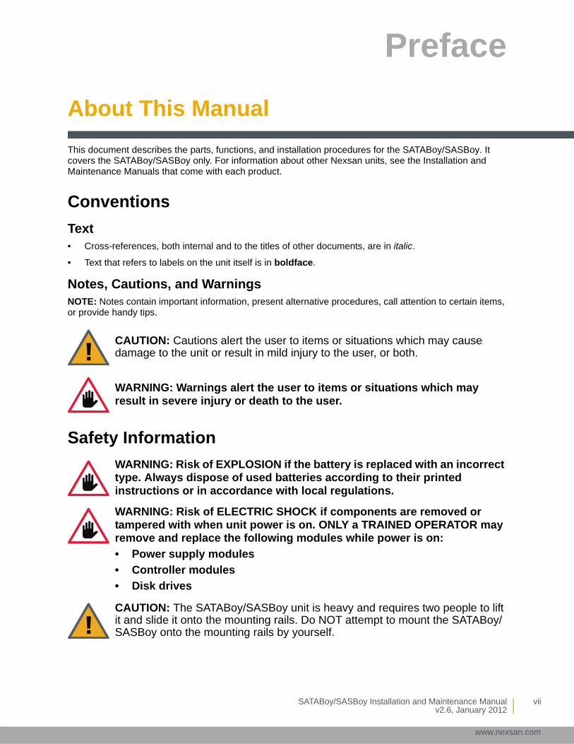
CAUTION: Cautions alert the user to items or situations which may cause damage to the unit or result in mild injury to the user, or both.
WARNING: Warnings alert the user to items or situations which may result in severe injury or death to the user.
WARNING: Risk of EXPLOSION if the battery is replaced with an incorrect type. Always dispose of used batteries according to their printed instructions or in accordance with local regulations.
WARNING: Risk of ELECTRIC SHOCK if components are removed or tampered with when unit power is on. ONLY a TRAINED OPERATOR may remove and replace the following modules while power is on:
• Power supply modules
• Controller modules
• Disk drives
CAUTION: The SATABoy/SASBoy unit is heavy and requires two people to lift it and slide it onto the mounting rails. Do NOT attempt to mount the SATABoy/SASBoy onto the mounting rails by yourself.
SATABoy/SASBoy Installation and Maintenance Manualv2.6, January 2012
vii
www.nexsan.com

About This Manual
viii
www.ne
Revision HistoryThis section lists updates and new material added to the SATABoy/SASBoy Installation and Maintenance Manual.
Version 2.6, January 2012: Changed name of document from “Hardware Manual” to “Installation and Maintenance Manual” throughout; added unpacking instructions on page 5; added required tools and equipment section on page 7.
Version 2.5, August 2011: Complete reorganization of Installation and Maintenance Manual contents.
Version 2.4, March 2011: Updated illustration of PSU on page 16.
Version 2.3, March 2010: New format applied throughout; new note regarding multiple SATABoy/SASBoy units added under Before you begin on page 5, under Disk Drives on page 12, and under Tiered Storage & SAS Drive installation guide on page 27.
CAUTION: When removing the SATABoy/SASBoy from the packaging, DO NOT lift the unit by any plastic parts or module handles on the chassis. Doing so may cause damage to the chassis or to internal components, or both. Lift the unit ONLY by the bottom edges of the chassis, using safe lifting practices.
CAUTION: Computer components and disk drives are sensitive to electrostatic discharge (ESD). Be sure to ground any electrostatic charge from your person before touching components with your hands or with any tools. While installing the unit, use the anti-static wrist-strap shipped with the SATABoy/SASBoy.
CAUTION: Always fully stabilize racks with wall anchors or stabilizing legs, or both, before mounting the SATABoy/SASBoy or any other components on the rack.
CAUTION: Ensure that the floor beneath the mounting rack has enough load-bearing capacity to support the rack and all mounted components.
CAUTION: Always fully secure all rack-mounting hardware when installing the SATABoy/SASBoy in a rack. Insufficient rack-mount support may allow the unit to fall onto other rack-mounted hardware or onto the floor, potentially damaging equipment or causing injury to nearby personnel.
CAUTION: When applying power to the SATABoy/SASBoy, use ONLY the IEC power cords originally supplied with the unit. Do NOT use other power cords, even if they appear identical to the supplied cords.
SATABoy/SASBoy Installation and Maintenance Manualv2.6, January 2012
xsan.com
Chapter 1
SATABoy/SASBoy Overview
Front Panel
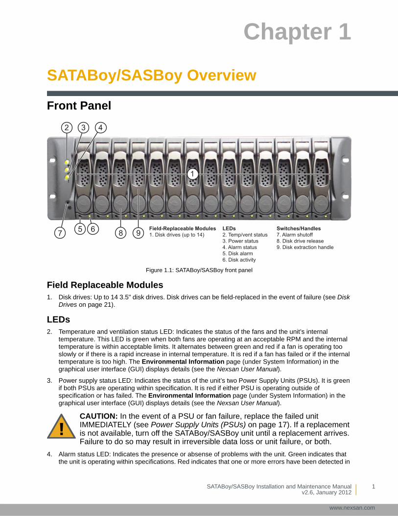
Figure 1.1: SATABoy/SASBoy front panel
Field Replaceable Modules1. Disk drives: Up to 14 3.5" disk drives. Disk drives can be field-replaced in the event of failure (see Disk
Drives on page 21).
LEDs2. Temperature and ventilation status LED: Indicates the status of the fans and the unit’s internal
temperature. This LED is green when both fans are operating at an acceptable RPM and the internal temperature is within acceptable limits. It alternates between green and red if a fan is operating too slowly or if there is a rapid increase in internal temperature. It is red if a fan has failed or if the internal temperature is too high. The Environmental Information page (under System Information) in the graphical user interface (GUI) displays details (see the Nexsan User Manual).
3. Power supply status LED: Indicates the status of the unit’s two Power Supply Units (PSUs). It is green if both PSUs are operating within specification. It is red if either PSU is operating outside of specification or has failed. The Environmental Information page (under System Information) in the graphical user interface (GUI) displays details (see the Nexsan User Manual).
4. Alarm status LED: Indicates the presence or absense of problems with the unit. Green indicates that the unit is operating within specifications. Red indicates that one or more errors have been detected in
CAUTION: In the event of a PSU or fan failure, replace the failed unit IMMEDIATELY (see Power Supply Units (PSUs) on page 17). If a replacement is not available, turn off the SATABoy/SASBoy unit until a replacement arrives. Failure to do so may result in irreversible data loss or unit failure, or both.
1
2 3 4
5 67 8 9Field-Replaceable Modules1. Disk drives (up to 14)
LEDs2. Temp/vent status3. Power status4. Alarm status5. Disk alarm6. Disk activity
Switches/Handles7. Alarm shutoff8. Disk drive release9. Disk extraction handle
SATABoy/SASBoy Installation and Maintenance Manualv2.6, January 2012
1
www.nexsan.com
Chapter 1 — SATABoy/SASBoy Overview
2
www.ne
the RAID Controllers or some other system (but not the PSUs or fans—see items 2 and 3). The Problems page (under System Information) in the graphical user interface (GUI) displays information about the event which triggered the alarm (see the Nexsan User Manual).
5. Disk drive alarm LEDs (one per drive): This LED flashes amber to warn you of a potentially unreliable disk drive. It is solid amber when the drive fails. The Disk Information page (under RAID Information) in the graphical user interface (GUI) displays details (see the Nexsan User Manual).
6. Disk drive activity LEDs (one per drive): This LED is green when a drive is installed in the drive slot. It blinks green during disk access activity.
Switches and Handles7. Alarm shutoff switch: Silences the audible alarm. Insert a thin object, such as an unfolded paper clip,
into the slot to press this button. The alarm will sound again if any additional errors occur.
8. Disk release button (one per drive): Releases the disk extraction handle.
9. Disk extraction handle (one per drive): Allows removal of the disk drive from the chassis.
Rear Panel
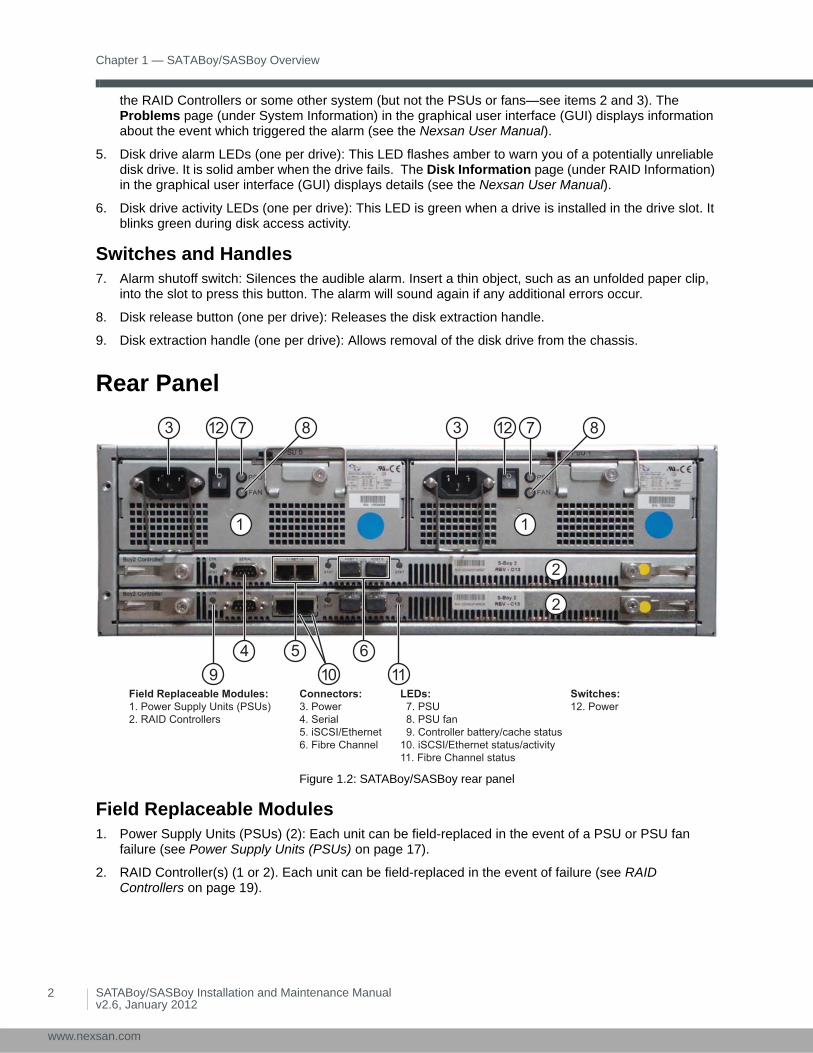
Figure 1.2: SATABoy/SASBoy rear panel
Field Replaceable Modules1. Power Supply Units (PSUs) (2): Each unit can be field-replaced in the event of a PSU or PSU fan
failure (see Power Supply Units (PSUs) on page 17).
2. RAID Controller(s) (1 or 2). Each unit can be field-replaced in the event of failure (see RAID Controllers on page 19).
1
2
3
1
2
4 5 6
7 8
9 10 11
12 3 7 812
Field Replaceable Modules:1. Power Supply Units (PSUs)2. RAID Controllers
Connectors:3. Power4. Serial5. iSCSI/Ethernet6. Fibre Channel
LEDs: 7. PSU 8. PSU fan 9. Controller battery/cache status10. iSCSI/Ethernet status/activity11. Fibre Channel status
Switches:12. Power
SATABoy/SASBoy Installation and Maintenance Manualv2.6, January 2012
xsan.com
Rear Panel
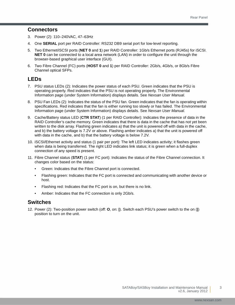
Connectors3. Power (2): 110–240VAC, 47–63Hz
4. One SERIAL port per RAID Controller: RS232 DB9 serial port for low-level reporting.
5. Two Ethernet/iSCSI ports (NET 0 and 1) per RAID Controller: 1Gb/s Ethernet ports (RJ45s) for iSCSI. NET 0 can be connected to a local area network (LAN) in order to configure the unit through the browser-based graphical user interface (GUI).
6. Two Fibre Channel (FC) ports (HOST 0 and 1) per RAID Controller: 2Gb/s, 4Gb/s, or 8Gb/s Fibre Channel optical SFPs.
LEDs7. PSU status LEDs (2): Indicates the power status of each PSU. Green indicates that the PSU is
operating properly. Red indicates that the PSU is not operating properly. The Environmental Information page (under System Information) displays details. See Nexsan User Manual.
8. PSU Fan LEDs (2): Indicates the status of the PSU fan. Green indicates that the fan is operating within specifications. Red indicates that the fan is either running too slowly or has failed. The Environmental Information page (under System Information) displays details. See Nexsan User Manual.
9. Cache/Battery status LED (CTR STAT) (1 per RAID Controller): Indicates the presence of data in the RAID Controller’s cache memory. Green indicates that there is data in the cache that has not yet been written to the disk array. Flashing green indicates a) that the unit is powered off with data in the cache, and b) the battery voltage is 7.2V or above. Flashing amber indicates a) that the unit is powered off with data in the cache, and b) that the battery voltage is below 7.2V.
10. iSCSI/Ethernet activity and status (1 pair per port): The left LED indicates activity; it flashes green when data is being transferred. The right LED indicates link status; it is green when a full-duplex connection of any speed is present.
11. Fibre Channel status (STAT) (1 per FC port): Indicates the status of the Fibre Channel connection. It changes color based on the status:
• Green: Indicates that the Fibre Channel port is connected.
• Flashing green: Indicates that the FC port is connected and communicating with another device or host.
• Flashing red: Indicates that the FC port is on, but there is no link.
• Amber: Indicates that the FC connection is only 2Gb/s.
Switches12. Power (2): Two-position power switch (off: O, on: |). Switch each PSU’s power switch to the on (|)
position to turn on the unit.
SATABoy/SASBoy Installation and Maintenance Manualv2.6, January 2012
3
www.nexsan.com
Chapter 1 — SATABoy/SASBoy Overview
4
www.ne
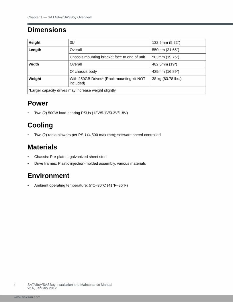
Dimensions
Power• Two (2) 500W load-sharing PSUs (12V/5.1V/3.3V/1.8V)
Cooling• Two (2) radio blowers per PSU (4,500 max rpm); software speed controlled
Materials• Chassis: Pre-plated, galvanized sheet steel
• Drive frames: Plastic injection-molded assembly, various materials
Environment• Ambient operating temperature: 5°C–30°C (41°F–86°F)
Height 3U 132.5mm (5.22")
Length Overall 550mm (21.65")
Chassis mounting bracket face to end of unit 502mm (19.76")
Width Overall 482.6mm (19")
Of chassis body 429mm (16.89")
Weight With 250GB Drives* (Rack mounting kit NOT included)
38 kg (83.78 lbs.)
*Larger capacity drives may increase weight slightly
SATABoy/SASBoy Installation and Maintenance Manualv2.6, January 2012
xsan.com

Chapter 2
Getting Started
This manual is designed to enable the user to install and configure the SATABoy/SASBoy quickly and safely. Please read this document carefully and review all of the information in this section before installing the SATABoy/SASBoy.
Taking Delivery of the SATABoy/SASBoyUpon receipt of your SATABoy/SASBoy, inspect the packaging for damage that may have been sustained in transit. If there is visible damage on the packaging, contact your shipper before proceeding.
Unpack the SATABoy/SASBoyCarefully unpack your SATABoy/SASBoy and inspect each item before installation:
1. Carefully cut the tape holding the box closed.
Figure 2.1: Opening the outer box
2. Remove the cardboard spacers and the disk box from the outer box.
Figure 2.2: Removing spacers and disk box
SATABoy/SASBoy Installation and Maintenance Manualv2.6, January 2012
5
www.nexsan.com
Chapter 2 — Getting Started
6
www.ne
3. Inspect the items in the foam spacer. The accessories should include:
• rack-mounting hardware:
two rail assemblies, one left and one righteight (8) large screws for securing the rails to the racktwo (2) bolts for securing the SATABoy/SASBoy to the rack
• two (2) power cables
• disposable ESD strap
• serial cable
• any additional items that may have been ordered, such as Fibre Channel cables
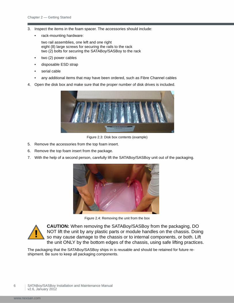
4. Open the disk box and make sure that the proper number of disk drives is included.
Figure 2.3: Disk box contents (example)
5. Remove the accessories from the top foam insert.
6. Remove the top foam insert from the package.
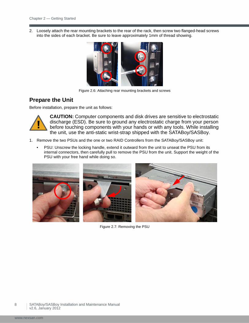
7. With the help of a second person, carefully lift the SATABoy/SASBoy unit out of the packaging.
Figure 2.4: Removing the unit from the box
The packaging that the SATABoy/SASBoy ships in is reusable and should be retained for future re-shipment. Be sure to keep all packaging components.
CAUTION: When removing the SATABoy/SASBoy from the packaging, DO NOT lift the unit by any plastic parts or module handles on the chassis. Doing so may cause damage to the chassis or to internal components, or both. Lift the unit ONLY by the bottom edges of the chassis, using safe lifting practices.
SATABoy/SASBoy Installation and Maintenance Manualv2.6, January 2012
xsan.com

Before Installation
Before Installation
Required Tools and EquipmentTo perform the installation, you will need the following tools and equipment:
• a suitable equipment rack with sufficient load capacity to hold the SATABoy/SASBoy
• a size P1 Phillips-head screwdriver
• enough CAT6 Ethernet cable to connect the SATABoy/SASBoy to the local area network (LAN)
• enough CAT6 Ethernet cable, fibre-optic cable, or twisted-pair copper cable to connect the SATABoy/SASBoy to the storage area network (SAN) (see Attach Communication Cables on page 16)
Prepare the SiteBefore installing the SATABoy/SASBoy, prepare the installation site and rack as follows:
• Ensure that the ambient temperature at the installation site is between 5°C (41°F) and 30°C (86°F). If the temperature at the site is not actively regulated, ensure that daily and seasonal temperature changes will not result in the ambient temperature going outside these limits.
• Situate the rack so that full air flow at both the front and the rear of the SATABoy/SASBoy is possible.
• Ensure that the rack is properly grounded per the manufacturer’s instructions and that proper ESD safeguards are in place.
• Ensure that the power drawn by the SATABoy/SASBoy does not overload the available electrical supply (see Power on page 4).
Attach Rack Mounting Hardware1. At a suitable location in the front of the rack, insert the cage nuts.
Figure 2.5: Attaching the cage nuts
CAUTION: Always fully stabilize racks with wall anchors or stabilizing legs, or both, before mounting the SATABoy/SASBoy or any other components on the rack.
CAUTION: Ensure that the floor beneath the mounting rack has enough load-bearing capacity to support the rack and all mounted components.
SATABoy/SASBoy Installation and Maintenance Manualv2.6, January 2012
7
www.nexsan.com
Chapter 2 — Getting Started
8
www.ne
2. Loosely attach the rear mounting brackets to the rear of the rack, then screw two flanged-head screws into the sides of each bracket. Be sure to leave approximately 1mm of thread showing.
Figure 2.6: Attaching rear mounting brackets and screws
Prepare the UnitBefore installation, prepare the unit as follows:
1. Remove the two PSUs and the one or two RAID Controllers from the SATABoy/SASBoy unit:
• PSU: Unscrew the locking handle, extend it outward from the unit to unseat the PSU from its internal connectors, then carefully pull to remove the PSU from the unit. Support the weight of the PSU with your free hand while doing so.
Figure 2.7: Removing the PSU
CAUTION: Computer components and disk drives are sensitive to electrostatic discharge (ESD). Be sure to ground any electrostatic charge from your person before touching components with your hands or with any tools. While installing the unit, use the anti-static wrist-strap shipped with the SATABoy/SASBoy.
SATABoy/SASBoy Installation and Maintenance Manualv2.6, January 2012
xsan.com
Before Installation
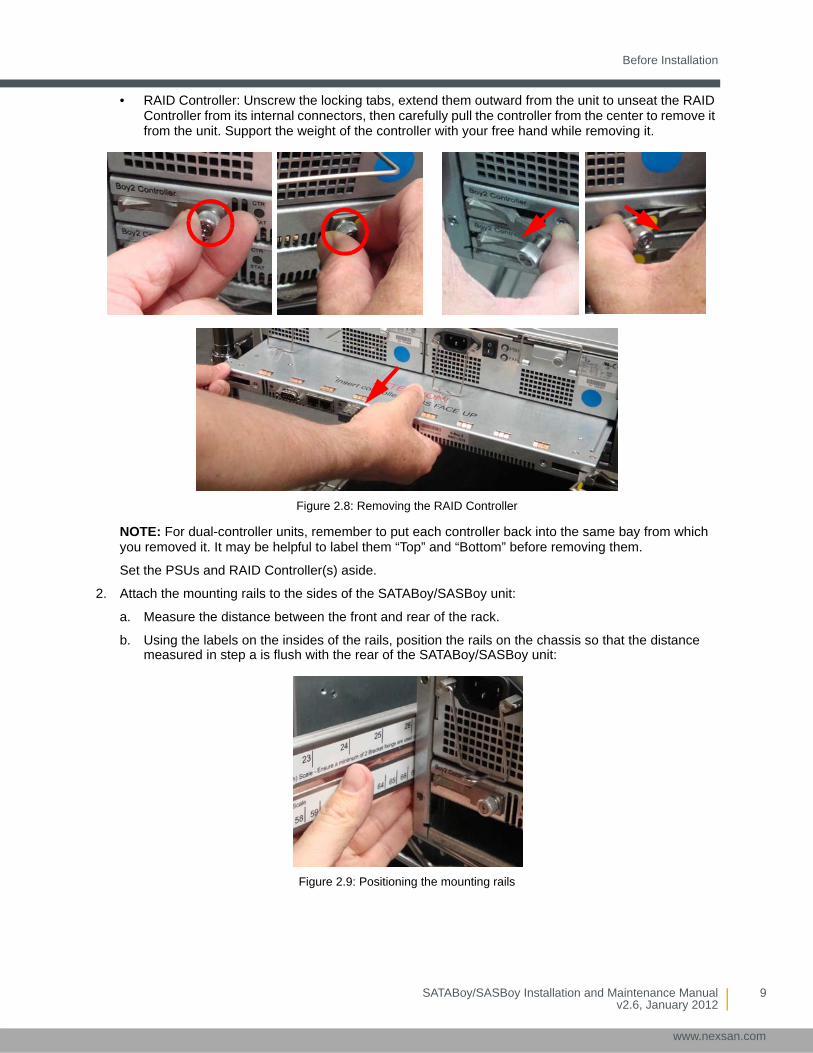
• RAID Controller: Unscrew the locking tabs, extend them outward from the unit to unseat the RAID Controller from its internal connectors, then carefully pull the controller from the center to remove it from the unit. Support the weight of the controller with your free hand while removing it.
Figure 2.8: Removing the RAID Controller
NOTE: For dual-controller units, remember to put each controller back into the same bay from which you removed it. It may be helpful to label them “Top” and “Bottom” before removing them.
Set the PSUs and RAID Controller(s) aside.
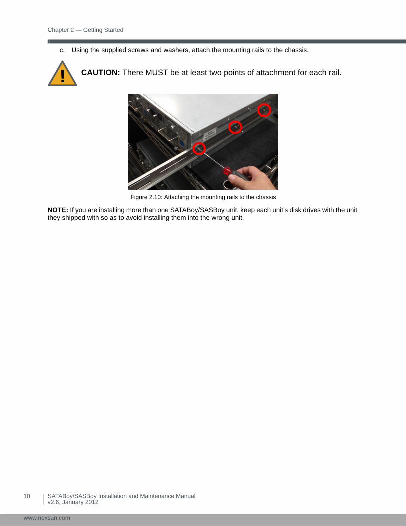
2. Attach the mounting rails to the sides of the SATABoy/SASBoy unit:
a. Measure the distance between the front and rear of the rack.
b. Using the labels on the insides of the rails, position the rails on the chassis so that the distance measured in step a is flush with the rear of the SATABoy/SASBoy unit:
Figure 2.9: Positioning the mounting rails
SATABoy/SASBoy Installation and Maintenance Manualv2.6, January 2012
9
www.nexsan.com
Chapter 2 — Getting Started
10
www.ne
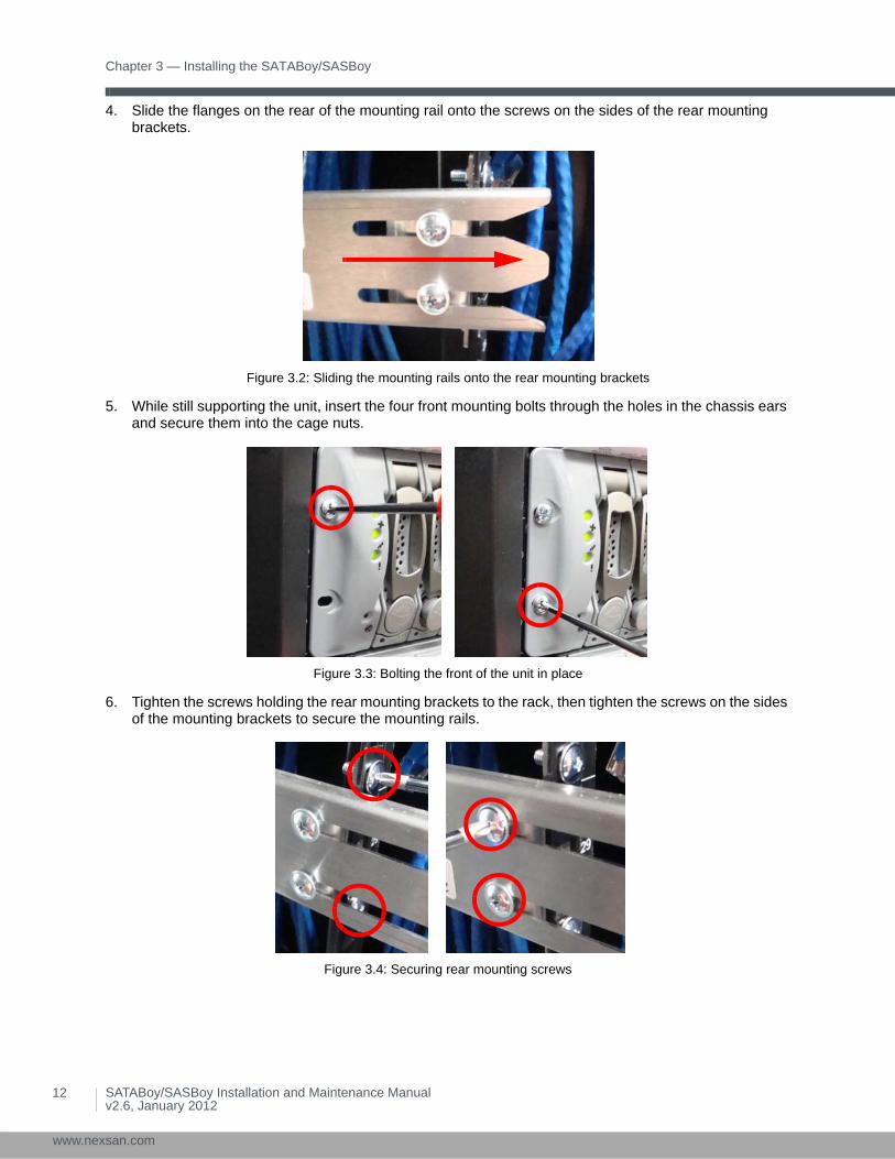
c. Using the supplied screws and washers, attach the mounting rails to the chassis.
Figure 2.10: Attaching the mounting rails to the chassis
NOTE: If you are installing more than one SATABoy/SASBoy unit, keep each unit’s disk drives with the unit they shipped with so as to avoid installing them into the wrong unit.
CAUTION: There MUST be at least two points of attachment for each rail.
SATABoy/SASBoy Installation and Maintenance Manualv2.6, January 2012
xsan.com

Chapter 3
Installing the SATABoy/SASBoy
The SATABoy/SASBoy comes in single-controller and dual-controller configurations. These instructions assume a dual-controller unit installation, but where the steps differ, additional instructions for single-controller units are provided.
Mount the SATABoy/SASBoy
1. Ground any electrostatic charge from your person by touching a metal part of the rack.
2. Attach one end of the disposable anti-static wrist-strap to a metal part of the rack. Wrap the other end around your wrist. Both people lifting the unit should do this.
Figure 3.1: Putting on and attaching the anti-static wrist-strap.
3. With the help of a second person, lift the SATABoy/SASBoy unit and insert it between the left and right rack sections.
CAUTION: Computer components and disk drives are sensitive to electrostatic discharge (ESD). Be sure to ground any electrostatic charge from your person before touching components with your hands or with any tools. While installing the unit, use the anti-static wrist-strap shipped with the SATABoy/SASBoy.
CAUTION: The SATABoy/SASBoy unit is heavy and requires two people to lift it and slide it onto the mounting rails. Do NOT attempt to mount the SATABoy/SASBoy onto the mounting rails by yourself.
CAUTION: Only support the unit by placing hands under the metal chassis. Do NOT attempt to lift the unit by any plastic parts or module handles.
CAUTION: Before mounting the unit, be sure that it is oriented properly. The unit is right side up when the LEDs on the front panel are on the left, as shown in the illustration under Front Panel on page 1.
SATABoy/SASBoy Installation and Maintenance Manualv2.6, January 2012
11
www.nexsan.com
Chapter 3 — Installing the SATABoy/SASBoy
12
www.ne
4. Slide the flanges on the rear of the mounting rail onto the screws on the sides of the rear mounting brackets.
Figure 3.2: Sliding the mounting rails onto the rear mounting brackets
5. While still supporting the unit, insert the four front mounting bolts through the holes in the chassis ears and secure them into the cage nuts.
Figure 3.3: Bolting the front of the unit in place
6. Tighten the screws holding the rear mounting brackets to the rack, then tighten the screws on the sides of the mounting brackets to secure the mounting rails.
Figure 3.4: Securing rear mounting screws
SATABoy/SASBoy Installation and Maintenance Manualv2.6, January 2012
xsan.com

Restore the Rear Modules
Restore the Rear Modules
PSUsInsert the two PSUs into the back of the unit:
1. Make sure that the PSU is right side up. The latching handle should be on top. See Rear Panel on page 2.
2. Insert the PSU into the slot and carefully slide it into the slot until it stops moving.
Figure 3.5: Sliding the PSU into place
3. Swivel the latching handle to the right so that it is flush with the PSU, then tighten the retaining bolt to lock the handle in place.
Figure 3.6: Seating and locking the PSU into place
4. Repeat steps 1 through 3 for the second PSU.
NOTE: Do not connect the power cords to the PSUs at this time.
SATABoy/SASBoy Installation and Maintenance Manualv2.6, January 2012
13
www.nexsan.com

Chapter 3 — Installing the SATABoy/SASBoy
14
www.ne
RAID ControllersInsert the one or two RAID Controllers into the back of the unit:
1. Make sure that the RAID Controller is right side up. There is a notice in red on the top of the controller to guide you.
2. Insert the RAID Controller into the slot and carefully slide it back until it stops moving.
Figure 3.7: Sliding the RAID Controller into place
3. Swivel the latching tabs inward to seat the RAID Controller.
Figure 3.8: Seating the RAID Controllers with the latch tabs
4. Tighten the retaining bolts to lock the RAID Controller in place.
Figure 3.9: Locking the RAID Controller in place
5. Repeat steps 1 through 4 for the second RAID Controller, if present.
SATABoy/SASBoy Installation and Maintenance Manualv2.6, January 2012
xsan.com

Load Disk Drives
Load Disk Drives1. Using the drive guides to help you orient the disks, carefully load each disk drive into a drive slot, push
down on the extraction handle to seat it, and lock the handle in place with the drive release button:
Figure 3.10: Inserting disk drives
2. For any slots where a disk drive is not present, insert a blank drive slot plate into the drive slot:
NOTE: You may have to press the latch at the top to seat the plate fully.
Figure 3.11: Inserting blank drive slot plates
CAUTION: Always fill all drive slots across the front of the unit. Leaving open gaps decreases cooling efficiency and may result in some disk drives overheating.
SATABoy/SASBoy Installation and Maintenance Manualv2.6, January 2012
15
www.nexsan.com

Chapter 3 — Installing the SATABoy/SASBoy
16
www.ne
Attach Communication CablesConnect all necessary communication cables to the RAID Controller (or Controllers) on the rear of the unit (see Rear Panel on page 2):
• If you have a 1Gb iSCSI network, attach CAT6 Ethernet cables to the iSCSI ports (Net 0 and 1).
• If you have a Fibre Channel network, attach fiber-optic cables or twisted-pair copper cables to the Fibre Channel ports (Host 0 or Host 1).
Power Up the SATABoy/SASBoy
• Using the two supplied power cords, connect each PSU to main power, making sure to fold down the retaining clip over each one. Then turn the unit on by switching each PSU’s power switch to the on (|) position:
Figure 3.12: Powering up the SATABoy/SASBoy
Once the unit has finished booting up, you can configure it using the graphical user interface (GUI). For detailed instructions, see the Nexsan User Manual.
CAUTION: When applying power to the SATABoy/SASBoy, use ONLY the IEC power cords originally supplied with the unit. Do NOT use other power cords, even if they appear identical to the supplied cords.
SATABoy/SASBoy Installation and Maintenance Manualv2.6, January 2012
xsan.com
Chapter 4
Field Replacement of Modules
The SATABoy/SASBoy is designed so that some of its components can be replaced without turning off the unit or interrupting its functioning. The field-replaceable modules are:
• the two PSUs
• the one or two RAID Controllers
• the disk drives
This chapter describes how to replace each of these modules in the field while the unit is running.
Power Supply Units (PSUs)In the event of a power supply or PSU fan failure, replace the PSU using the following procedure. Do NOT remove a failed PSU without a replacement unit immediately available.
1. Determine which PSU or PSU fan has failed by examining the PSU status LEDs on each module (see Rear Panel on page 2). A red LED indicates the failed module. The Home page of the graphical user interface (GUI) also tells you which unit has failed (see the Nexsan User Manual).
2. On the PSU where the failure has occurred, switch the PSU’s power switch to the off (O) position, then remove the power cable from the power cable socket.
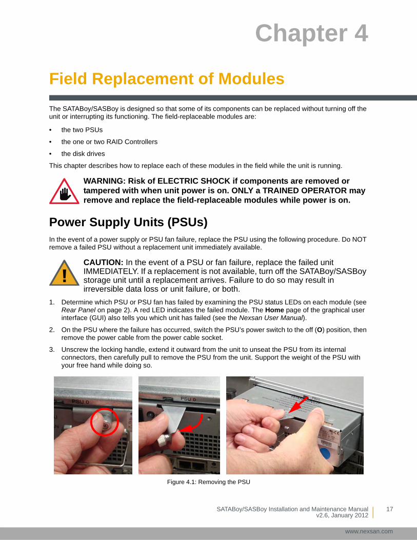
3. Unscrew the locking handle, extend it outward from the unit to unseat the PSU from its internal connectors, then carefully pull to remove the PSU from the unit. Support the weight of the PSU with your free hand while doing so.
Figure 4.1: Removing the PSU
WARNING: Risk of ELECTRIC SHOCK if components are removed or tampered with when unit power is on. ONLY a TRAINED OPERATOR may remove and replace the field-replaceable modules while power is on.
CAUTION: In the event of a PSU or fan failure, replace the failed unit IMMEDIATELY. If a replacement is not available, turn off the SATABoy/SASBoy storage unit until a replacement arrives. Failure to do so may result in irreversible data loss or unit failure, or both.
SATABoy/SASBoy Installation and Maintenance Manualv2.6, January 2012
17
www.nexsan.com

Chapter 4 — Field Replacement of Modules
18
www.ne
4. Make sure that the replacement PSU is right-side up. The power cable socket should be on the upper left. See Rear Panel on page 2.
5. Insert the PSU into the slot and carefully slide it into the slot until it stops moving.
Figure 4.2: Sliding the PSU into place
6. Swivel the latching handle to the left so that it is flush with the PSU, then tighten the retaining bolt to lock the handle in place.
Figure 4.3: Seating and locking the PSU into place
7. Plug the power cable into the power cable socket on the replacement PSU and switch the PSU’s power switch to the on (|) position.
The two PSU status LEDs light up green to indicate that the unit is functioning properly and supplying power to the SATABoy/SASBoy unit.
8. In the graphical user interface (GUI), go to the Home page and verify that the status bar for the new Power Supply Unit is green. See the Nexsan User Manual for more information.
SATABoy/SASBoy Installation and Maintenance Manualv2.6, January 2012
xsan.com
RAID Controllers
RAID ControllersIn the event of a RAID Controller failure, replace the controller using the following procedure:
1. Determine which RAID Controller has failed by checking the Home page of the graphical user interface (GUI) (see the Nexsan User Manual).
NOTE: In some cases, a RAID Controller needs to be replaced even if it has not failed outright. In this case, you must determine which RAID Controller to replace by following the troubleshooting procedures in the Nexsan User Manual.
2. Do one of the following:
• If you have a dual-controller unit, navigate to System Admin > Reboot in the graphical user interface (GUI). Under Controller Maintenance, select the controller that has failed, select the confirmation check box, then click Execute NOW.
• If you have a single-controller unit, navigate to System Admin > Reboot in the graphical user interface (GUI), select System Shutdown, select the confirmation check box, then click Execute NOW. Then switch the power switches on both PSUs to the off (O) position.
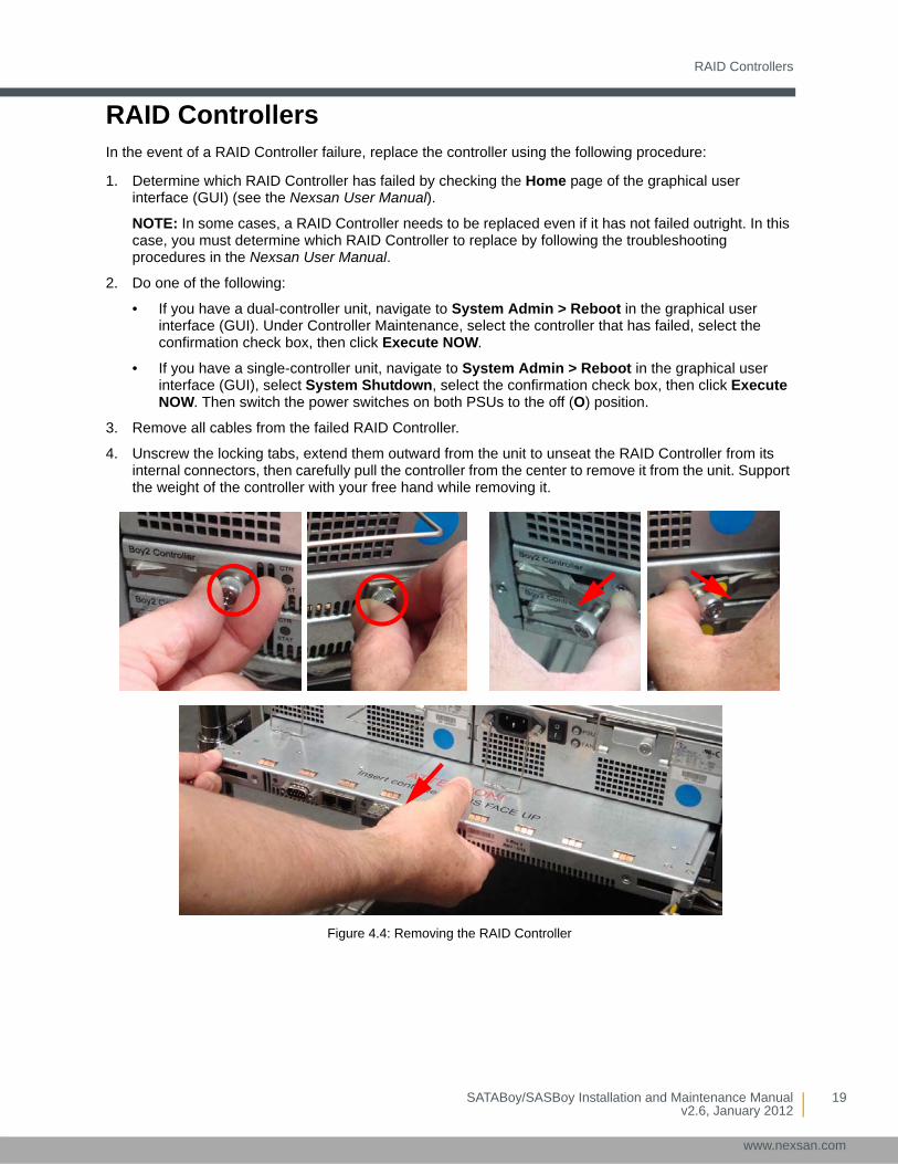
3. Remove all cables from the failed RAID Controller.
4. Unscrew the locking tabs, extend them outward from the unit to unseat the RAID Controller from its internal connectors, then carefully pull the controller from the center to remove it from the unit. Support the weight of the controller with your free hand while removing it.
Figure 4.4: Removing the RAID Controller
SATABoy/SASBoy Installation and Maintenance Manualv2.6, January 2012
19
www.nexsan.com
Chapter 4 — Field Replacement of Modules
20
www.ne
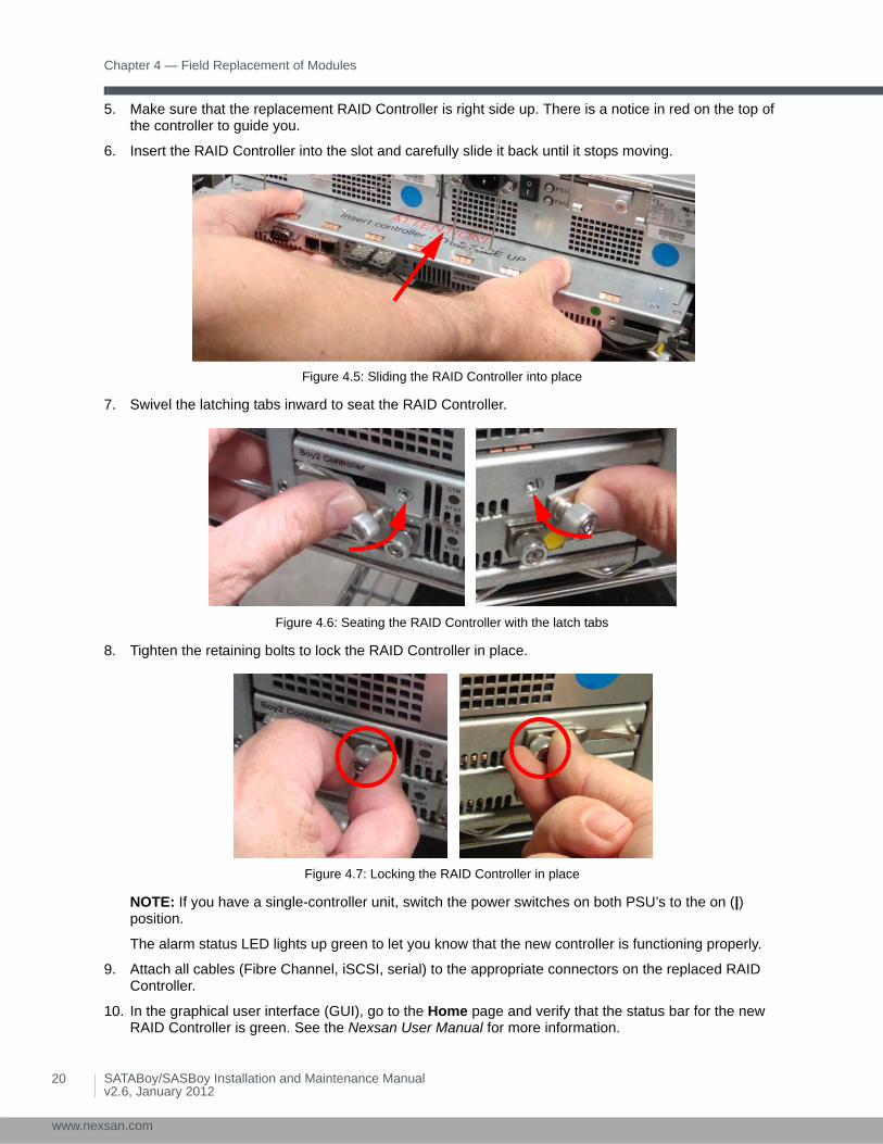
5. Make sure that the replacement RAID Controller is right side up. There is a notice in red on the top of the controller to guide you.
6. Insert the RAID Controller into the slot and carefully slide it back until it stops moving.
Figure 4.5: Sliding the RAID Controller into place
7. Swivel the latching tabs inward to seat the RAID Controller.
Figure 4.6: Seating the RAID Controller with the latch tabs
8. Tighten the retaining bolts to lock the RAID Controller in place.
Figure 4.7: Locking the RAID Controller in place
NOTE: If you have a single-controller unit, switch the power switches on both PSU’s to the on (|) position.
The alarm status LED lights up green to let you know that the new controller is functioning properly.
9. Attach all cables (Fibre Channel, iSCSI, serial) to the appropriate connectors on the replaced RAID Controller.
10. In the graphical user interface (GUI), go to the Home page and verify that the status bar for the new RAID Controller is green. See the Nexsan User Manual for more information.
SATABoy/SASBoy Installation and Maintenance Manualv2.6, January 2012
xsan.com

Disk Drives
Disk DrivesIn the event of a disk drive failure, replace the drive using the following procedure.
1. Determine which drive has failed by examining the LEDs for each disk (see Front Panel on page 1). A red LED indicates the failed drive. The Disk Drives page (under RAID Information) of the graphical user interface (GUI) also tells you which drive has failed (see the Nexsan User Manual).
2. Press the disk release button for the failed drive, then remove the drive by carefully pulling on the extraction handle. Support the disk with your free hand while removing it.
Figure 4.8: Removing a disk drive
3. Using the drive guides to help you orient the disk, carefully load the replacement disk drive into the drive slot, push down on the extraction handle, then lock it into place with the disk release button.
Figure 4.9: Replacing a disk drive
The drive status LED lights up green to let you know that the disk is connected and functioning properly.
4. In the graphical user interface (GUI), go to the Home page and verify that the status bar for the new drive is blue, meaning that it has been automatically detected and assigned as a pool spare. See the Nexsan User Manual for more information.
NOTE: If the status bar for the new drive is red, you must manually assign the drive. See the Nexsan User Manual for instructions.
CAUTION: Do not lean on or place any heavy object on the unit while inserting or replacing disk drives. Doing so may damage the unit or overbalance the rack.
SATABoy/SASBoy Installation and Maintenance Manualv2.6, January 2012
21
www.nexsan.com
Chapter 4 — Field Replacement of Modules
22
www.ne
SATABoy/SASBoy Installation and Maintenance Manualv2.6, January 2012
xsan.com

Common Terms and Abbreviations
Common Terms and Abbreviations
anti-static wrist-strapAn antistatic device used to prevent electrostatic discharge (ESD) by safely grounding a person working on electronic equipment. Also called an ESD strap or a grounding bracelet.
arrayA linked group of one or more physical, independent hard disk drives. On Nexsan storage systems, synonymous with RAID.
bitThe smallest unit of digital data, representing a 0 or a 1. Abbreviated “b”.
byteA unit of data that is 8 bits long. Often used for alphanumeric characters. Abbreviated “B”.
cacheReserved areas of memory that are used to speed up instruction execution, data retrieval, and data updating. In Nexsan storage units, a flash memory unit in the RAID Controller that temporarily holds user data.
duplexA communication system where data flows in both directions between two devices. There are two configurations. “Half duplex” provides communication in both directions, but not at the same time; when one device transmits, the other device can only receive, and vice versa. For example, walkie-talkies, police radios, and other two-way radio systems use half duplex communication. “Full duplex” allows both devices to send information simultaneously. For example, telephones and videoconferencing systems use full-duplex communication.
electrostatic dischargeThe sudden and momentary electric current that flows between two objects at different electrical potentials caused by direct contact or induced by an electrostatic field. Potentially harmful to electronic components.
ESDSee electrostatic discharge.
ESD strapSee anti-static wrist-strap.
EthernetA system for connecting a number of computer systems to form a local area network (LAN), with protocols to control the passing of information and to avoid simultaneous transmission by two or more systems. Supports data transfer rates of 10, 100, 1,000, and 10,000 megabits per second (Mb/s). 10, 100, and 1,000Mb/s networks are often referred to as 10BASE-T, 100BASE-T, and 1000BASE-T, respectively. 10,000Mb/s networks are usually referred to as 10Gb Ethernet or 10GbE.
FC portSee Fibre Channel port.
SATABoy/SASBoy Installation and Maintenance Manualv2.6, January 2012
23
www.nexsan.com
Common Terms and Abbreviations
24
www.ne
FCCThe Federal Communications Commission. The federal agency that regulates electromagnetic emissions.
Fibre ChannelA gigabit (Gb) speed network technology primarily used for storage networking and the current standard connection type for storage area networks (SANs). Despite its name, Fibre Channel signaling can run on both twisted-pair copper wire and fiber-optic cables.
Fibre Channel portAny entity that actively communicates over a Fibre Channel network. Usually implemented in a device such as disk storage or a Fibre Channel switch. In Nexsan storage units, the Fibre Channel ports support 2Gb/s, 4Gb/s, or 8Gb/s connections.
Fibre Channel switchA network switch compatible with the Fibre Channel protocol. Allows the creation of a Fibre Channel network, which is currently the core component of most storage area networks (SANs).
full duplexSee duplex.
GbGigabit. Approximately one billion (1,000,000,000) bits.
GBGigabyte. Approximately one billion (1,000,000,000) bytes. Used to describe the storage capacity of hard disk drives. A gigabyte is usually computed as 109 (1,000,000,000) bytes, but can also be computed as 230 (1,073,741,824) bytes (often called a “binary gigabyte” and abbreviated GiB).
GBICSee gigabit interface converter.
Gb/sGigabits (Gb) per second. Used to describe the speed of network data transmission.
gigabit interface converterA standard for transceivers, commonly used with Gigabit (Gb) Ethernet and Fibre Channel, with a hot-swappable electrical interface. Gigabit interface converter ports can support a wide range of physical media, from copper to optical fiber, at lengths of hundreds of kilometers.
graphical user interfaceA type of user interface that allows users to interact with electronic devices using images rather than text commands. Nexsan storage units use a graphical user interface for system configuration.
grounding braceletSee anti-static wrist-strap.
GUISee graphical user interface.
IECThe International Electrotechnical Commission. Prepares and publishes international standards for all electrical, electronic, and related technologies.
I/OInput/Output. The communication between an information processing system (such as a computer or a SATABoy/SASBoy storage system’s RAID Controller), and the outside world (either an operator or
SATABoy/SASBoy Installation and Maintenance Manualv2.6, January 2012
xsan.com

Common Terms and Abbreviations
another information processing system). Inputs are the signals or data received by the system, and outputs are the signals or data sent from it.
IP addressInternet Protocol address. A numerical label assigned to each device (such as a computer, printer, or Nexsan storage unit) on a computer network that uses TCP/IP for communication.
iSCSIInternet Small Computer System Interface. A transport protocol that provides for the SCSI protocol to be carried over a TCP/IP network.
LANSee local area network.
LEDLight Emitting Diode. LEDs are used for indicator lights on the front and back of Nexsan storage units.
local area networkA computer network that links devices within a small geographic area, such as a building or group of adjacent buildings.
MbMegabit. Approximately one million (1,000,000) bits.
Mb/sMegabits (Mb) per second. Used to describe the speed of network data transmission.
Power Supply UnitA module that regulates electrical power to the components of Nexsan storage units.
PSUSee Power Supply Unit.
rackA metal frame designed to hold hardware devices.
rack mountHardware for attaching devices to a rack.
rack-mountedAttached to a rack.
RAIDRedundant Array of Independent Disks. A system using multiple hard drives organized into a single logical unit for the sharing or replication of data in order to increase data integrity, fault-tolerance, and throughput. RAIDs are organized into RAID levels, which describe their architecture and configuration.
RAID ControllerA hardware device, software program, or combination of the two which manages the physical disk drives in a RAID and presents them as a single logical unit to attached devices. The RAID controllers in Nexsan storage units are hardware modules. Nexsan RAID controllers also provide connections for system administration and configuration.
railA type of rack mount that allows a device to be easily mounted onto a rack.
SATABoy/SASBoy Installation and Maintenance Manualv2.6, January 2012
25
www.nexsan.com
Common Terms and Abbreviations
26
www.ne
SANSee storage area network.
SASSerial Attached SCSI. A serial version of the SCSI interface. A point-to-point architecture that uses a disk controller with four or more channels that operate simultaneously. Each full-duplex channel, known as a SAS port, transfers data at 1.5Gb/s, 3Gb/s, or 6Gb/s in each direction. SAS also supports Serial ATA (SATA) drives, which can be mixed with SAS drives in a variety of configurations.
SATASerial Advanced Technology Attachment. A connection standard for fixed and removable hard disk drives.
SCSISmall Computer System Interface. A collection of standards and proposed standards for input/output (I/O) communication, primarily intended for connecting storage subsystems or devices to hosts.
SFPSmall Form-factor Pluggable. A type of gigabit interface converter (GBIC) in a compact form factor. The Fibre Channel ports on Nexsan storage devices are SFPs.
spare diskA blank disk drive that is available to a RAID array in case any of the disks assigned to the array should fail. If an array disk fails, the RAID Controller rebuilds the data from the failed disk onto the spare disk, which then becomes part of the array. In Nexsan storage systems, there are two kinds of spare disk: “pool spares”, which can be used by any RAID array in the unit; and “dedicated spares”, which are assigned to a specific array.
storage area networkAn architecture that provides for attachment of remote computer storage devices to servers in such a way that the devices appear as locally attached to the operating system.
TBTerabyte. Approximately one trillion (1,000,000,000,000) bytes. Used to describe the storage capacity of hard disk drives. A terabyte is usually computed as 1012 (1,000,000,000,000) bytes, but can also be computed as 240 (1,099,511,627,776) bytes (often called a “binary terabyte” and abbreviated TiB).
TCP/IPTransmission Control Protocol/Internet Protocol. The set of communications protocols used for the Internet and other similar networks. TCP provides reliable delivery of messages between networked computers. IP uses numeric IP addresses to join network segments.
UUnit. The standard unit of measure for designating the vertical usable space, or height, of racks. 1U is equal to 1.75 inches. A device that is described as being 1U in height may be shorter than 1.75 inches, but, due to the design of most racks, will still take up 1.75 inches of rack space.
SATABoy/SASBoy Installation and Maintenance Manualv2.6, January 2012
xsan.com

NEXSAN Worldwide Headquarters — Los Angeles, USA1445 Lawrence DriveThousand Oaks, CA 91320
Telephone: 866-4-NEXSAN (866-463-9726), or 805-418-2700 outside of North America
On-Guard Technical Services: 866-2-NEXSAN (866-263-9726), or 760-690-1111 outside of North America
Fax: 805-418-2799
E-mail: [email protected], [email protected]
NEXSAN San Diego, USA302 Enterprise StreetEscondido, CA 92029
Telephone: 866-4-NEXSAN (866-463-9726), or 760-690-1100 outside of North America
On-Guard Technical Services: 866-2-Nexsan (866-263-9726), or 760-690-1111 outside of North America
Fax: 760-745-3503
E-mail: [email protected], [email protected]
NEXSAN Technologies, Ltd. — European Head Office, UKUnits 33–35 Parker Centre, Mansfield RoadDerby, DE21 4SZUnited Kingdom
Telephone: +44 (0)1332 291600
Fax: +44 (0)1332 291616
On-Guard Technical Services: +44 (0)1332 291600 Europe, 760-690-1111 USA
E-mail: [email protected], [email protected]
Copyright © 2009–2012 Nexsan Corporation. All Rights Reserved.
Nexsan®, SATABoy®, SASBoy™, and the Nexsan logo are trademarks or registered trademarks of Nexsan Corporation.
All other trademarks and registered trademarks are the property of their respective owners.
Version 2.6Release Date: January 2012